US9844844B2 - Automatic packaging line to pack profiles and rotor - Google Patents
Automatic packaging line to pack profiles and rotor Download PDFInfo
- Publication number
- US9844844B2 US9844844B2 US14/566,426 US201414566426A US9844844B2 US 9844844 B2 US9844844 B2 US 9844844B2 US 201414566426 A US201414566426 A US 201414566426A US 9844844 B2 US9844844 B2 US 9844844B2
- Authority
- US
- United States
- Prior art keywords
- profile
- magnets
- rotor
- packaging line
- conveyor
- Prior art date
- Legal status (The legal status is an assumption and is not a legal conclusion. Google has not performed a legal analysis and makes no representation as to the accuracy of the status listed.)
- Expired - Fee Related, expires
Links
- 238000004806 packaging method and process Methods 0.000 title claims abstract description 75
- 238000012546 transfer Methods 0.000 claims abstract description 37
- 210000004072 lung Anatomy 0.000 claims description 7
- 239000012530 fluid Substances 0.000 claims description 6
- 238000000034 method Methods 0.000 description 17
- 230000008878 coupling Effects 0.000 description 6
- 238000010168 coupling process Methods 0.000 description 6
- 238000005859 coupling reaction Methods 0.000 description 6
- 230000008569 process Effects 0.000 description 6
- 229910052751 metal Inorganic materials 0.000 description 4
- 239000002184 metal Substances 0.000 description 4
- 238000012856 packing Methods 0.000 description 4
- 229910000831 Steel Inorganic materials 0.000 description 3
- 230000008901 benefit Effects 0.000 description 3
- 238000001514 detection method Methods 0.000 description 3
- 238000006073 displacement reaction Methods 0.000 description 3
- 238000004519 manufacturing process Methods 0.000 description 3
- 230000007246 mechanism Effects 0.000 description 3
- 239000010959 steel Substances 0.000 description 3
- 229910000737 Duralumin Inorganic materials 0.000 description 2
- 229910052782 aluminium Inorganic materials 0.000 description 2
- XAGFODPZIPBFFR-UHFFFAOYSA-N aluminium Chemical compound [Al] XAGFODPZIPBFFR-UHFFFAOYSA-N 0.000 description 2
- 239000012467 final product Substances 0.000 description 2
- 238000012986 modification Methods 0.000 description 2
- 230000004048 modification Effects 0.000 description 2
- AILDTIZEPVHXBF-UHFFFAOYSA-N Argentine Natural products C1C(C2)C3=CC=CC(=O)N3CC1CN2C(=O)N1CC(C=2N(C(=O)C=CC=2)C2)CC2C1 AILDTIZEPVHXBF-UHFFFAOYSA-N 0.000 description 1
- 229910001335 Galvanized steel Inorganic materials 0.000 description 1
- 244000308495 Potentilla anserina Species 0.000 description 1
- 235000016594 Potentilla anserina Nutrition 0.000 description 1
- 230000004308 accommodation Effects 0.000 description 1
- 230000009471 action Effects 0.000 description 1
- 239000000872 buffer Substances 0.000 description 1
- 238000010276 construction Methods 0.000 description 1
- 239000008397 galvanized steel Substances 0.000 description 1
- 239000000463 material Substances 0.000 description 1
- 230000003287 optical effect Effects 0.000 description 1
- 230000009467 reduction Effects 0.000 description 1
- 230000000717 retained effect Effects 0.000 description 1
- 125000006850 spacer group Chemical group 0.000 description 1
- 238000013519 translation Methods 0.000 description 1
Images




Classifications
-
- B—PERFORMING OPERATIONS; TRANSPORTING
- B23—MACHINE TOOLS; METAL-WORKING NOT OTHERWISE PROVIDED FOR
- B23P—METAL-WORKING NOT OTHERWISE PROVIDED FOR; COMBINED OPERATIONS; UNIVERSAL MACHINE TOOLS
- B23P19/00—Machines for simply fitting together or separating metal parts or objects, or metal and non-metal parts, whether or not involving some deformation; Tools or devices therefor so far as not provided for in other classes
- B23P19/001—Article feeders for assembling machines
- B23P19/007—Picking-up and placing mechanisms
-
- B—PERFORMING OPERATIONS; TRANSPORTING
- B23—MACHINE TOOLS; METAL-WORKING NOT OTHERWISE PROVIDED FOR
- B23P—METAL-WORKING NOT OTHERWISE PROVIDED FOR; COMBINED OPERATIONS; UNIVERSAL MACHINE TOOLS
- B23P19/00—Machines for simply fitting together or separating metal parts or objects, or metal and non-metal parts, whether or not involving some deformation; Tools or devices therefor so far as not provided for in other classes
- B23P19/04—Machines for simply fitting together or separating metal parts or objects, or metal and non-metal parts, whether or not involving some deformation; Tools or devices therefor so far as not provided for in other classes for assembling or disassembling parts
-
- B—PERFORMING OPERATIONS; TRANSPORTING
- B65—CONVEYING; PACKING; STORING; HANDLING THIN OR FILAMENTARY MATERIAL
- B65B—MACHINES, APPARATUS OR DEVICES FOR, OR METHODS OF, PACKAGING ARTICLES OR MATERIALS; UNPACKING
- B65B27/00—Bundling particular articles presenting special problems using string, wire, or narrow tape or band; Baling fibrous material, e.g. peat, not otherwise provided for
- B65B27/10—Bundling rods, sticks, or like elongated objects
-
- B—PERFORMING OPERATIONS; TRANSPORTING
- B65—CONVEYING; PACKING; STORING; HANDLING THIN OR FILAMENTARY MATERIAL
- B65B—MACHINES, APPARATUS OR DEVICES FOR, OR METHODS OF, PACKAGING ARTICLES OR MATERIALS; UNPACKING
- B65B35/00—Supplying, feeding, arranging or orientating articles to be packaged
- B65B35/56—Orientating, i.e. changing the attitude of, articles, e.g. of non-uniform cross-section
- B65B35/58—Turning articles by positively-acting means, e.g. to present labelled portions in uppermost position
-
- B—PERFORMING OPERATIONS; TRANSPORTING
- B65—CONVEYING; PACKING; STORING; HANDLING THIN OR FILAMENTARY MATERIAL
- B65B—MACHINES, APPARATUS OR DEVICES FOR, OR METHODS OF, PACKAGING ARTICLES OR MATERIALS; UNPACKING
- B65B65/00—Details peculiar to packaging machines and not otherwise provided for; Arrangements of such details
- B65B65/003—Packaging lines, e.g. general layout
-
- B—PERFORMING OPERATIONS; TRANSPORTING
- B65—CONVEYING; PACKING; STORING; HANDLING THIN OR FILAMENTARY MATERIAL
- B65B—MACHINES, APPARATUS OR DEVICES FOR, OR METHODS OF, PACKAGING ARTICLES OR MATERIALS; UNPACKING
- B65B65/00—Details peculiar to packaging machines and not otherwise provided for; Arrangements of such details
- B65B65/003—Packaging lines, e.g. general layout
- B65B65/006—Multiple parallel packaging lines
-
- H—ELECTRICITY
- H01—ELECTRIC ELEMENTS
- H01F—MAGNETS; INDUCTANCES; TRANSFORMERS; SELECTION OF MATERIALS FOR THEIR MAGNETIC PROPERTIES
- H01F7/00—Magnets
- H01F7/02—Permanent magnets [PM]
-
- Y—GENERAL TAGGING OF NEW TECHNOLOGICAL DEVELOPMENTS; GENERAL TAGGING OF CROSS-SECTIONAL TECHNOLOGIES SPANNING OVER SEVERAL SECTIONS OF THE IPC; TECHNICAL SUBJECTS COVERED BY FORMER USPC CROSS-REFERENCE ART COLLECTIONS [XRACs] AND DIGESTS
- Y10—TECHNICAL SUBJECTS COVERED BY FORMER USPC
- Y10T—TECHNICAL SUBJECTS COVERED BY FORMER US CLASSIFICATION
- Y10T29/00—Metal working
- Y10T29/49—Method of mechanical manufacture
- Y10T29/49616—Structural member making
- Y10T29/49623—Static structure, e.g., a building component
-
- Y—GENERAL TAGGING OF NEW TECHNOLOGICAL DEVELOPMENTS; GENERAL TAGGING OF CROSS-SECTIONAL TECHNOLOGIES SPANNING OVER SEVERAL SECTIONS OF THE IPC; TECHNICAL SUBJECTS COVERED BY FORMER USPC CROSS-REFERENCE ART COLLECTIONS [XRACs] AND DIGESTS
- Y10—TECHNICAL SUBJECTS COVERED BY FORMER USPC
- Y10T—TECHNICAL SUBJECTS COVERED BY FORMER US CLASSIFICATION
- Y10T29/00—Metal working
- Y10T29/53—Means to assemble or disassemble
- Y10T29/53539—Means to assemble or disassemble including work conveyor
Definitions
- the present disclosure relates generally to a packaging line and, more particularly, to an automatic packaging line to pack profiles and a rotor.
- Opened structural profiles or molds such as those having a U-shaped or C-shaped cross-section, are often used in the lightweight steel construction industry, especially in structures used for industrial buildings and in the agricultural industry. These structural profiles are also used for housing and commercial structures, which reduce costs in materials such as, for example, labor, by the characteristics of its sections.
- the U-shaped or C-shaped section also optimizes the strength-weight relationship, which produces an excellent finish for the view elements.
- Spanish utility model application ES 1003449U refers to automatic equipment for packing profiles, especially those of aluminum. This equipment does not include duplex packaging and, therefore, does not reduce packaging space. Spanish utility model application ES 1037868U refers to a positioning wrapper for linear profiles. It also does not include duplex packaging of U- or C-shaped profiles or molds. As a result, the packages occupy more space. Spanish utility model application ES 2005394U refers to an automatic machine for packing profiles, especially those of aluminum. This equipment does not include duplex packaging of U- or C-shaped profiles or molds and, therefore, also does not provide the packaging space reduction.
- Spanish Patent ES 2232256 refers to a stacker machine of profiles of the kind that is established during the manufacturing and packaging of automated profiles, its carriage and grouping. It does not contemplate the packaging of duplexes of U- or C-shaped and, therefore, it does not reduce packaging space.
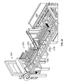
- FIG. 1 illustrates a perspective view of an example automatic packaging line to pack profiles and an example rotor in accordance with the teachings of this disclosure.
- FIG. 2 illustrates a perspective view of an example head carrying the example rotor of FIG. 1 .
- FIG. 3 illustrates a perspective view of the example rotor of FIG. 1 moving an example first profile by rotating and translating the first profile up and down while a second example profile is positioned below.
- FIG. 3 shows the example first profile in mid-rotation.
- FIG. 4 illustrates a perspective view of the example rotor of FIG. 1 and an example duplex formed by the example first profile and the example second profile of FIG. 3 .
- FIG. 5 illustrates a side view of the example head of FIG. 2 having an example servomotor to generate movement of the example head and an example magnetic stopper.
- FIG. 6 illustrates a rear perspective view of the example head and the example duplex of FIG. 4 .
- FIG. 7 illustrates a perspective view of the example automatic packaging line of FIG. 1 with an example lowering table, example pneumatic drives, example triggers and example transfer plates.
- FIG. 8A illustrates a top perspective view of the example rotor of FIG. 1 having example horizontal magnets and example vertical magnets.
- FIG. 8B illustrates a cross-sectional view of the example rotor of FIG. 8A taken along line 8 B- 8 B of FIG. 8A .
- FIG. 8C illustrates another top perspective view of the example rotor of FIG. 8A .
- FIG. 8D illustrates a cross-sectional view of the example rotor of FIG. 8C taken along line 8 D- 8 D of FIG. 8C .
- FIG. 8E illustrates a bottom perspective view of the example rotor of FIG. 8C .
- FIG. 9 illustrates the example rotor of FIG. 8A with portions of an example housing removed to expose the example vertical magnets.
- FIG. 10 illustrates an example profile coupled to the example rotor of FIG. 8A with example magnets facing the example profile to hold the example profile.
- FIG. 11 illustrates the example profile and example rotor of FIG. 10 with the example magnets in a rotated position to release the example profile.
- FIG. 12 illustrates a top perspective view of the example rotor of FIG. 8A with the example horizontal and vertical magnets removed to illustrate example openings in the example housing of FIG. 9 .
- FIGS. 13A, 13B, 13C, 13D and 13E illustrate perspective views of the example rotor of FIG. 1 in sequence during a carrying operation.
- FIGS. 13F, 13G, 13H, 131 and 13J illustrate side views of the example rotor positions of FIGS. 13A, 13B, 13C, 13D and 13E .
- FIG. 14 illustrates a perspective view of the example head and the example rotor of FIG. 2 with portions of the example head and rotor removed to expose a mechanism that enables the movement of the example rotor.
- FIG. 14 also illustrates an enlarged view of the rotor of FIG. 8A with the example vertical and horizontal magnets.
- FIG. 15 illustrates a perspective view of the example head and the example rotor of FIG. 14 .
- An example first profile supported by the example horizontal magnets is in rotation by the rotor.
- FIG. 15 also illustrates an enlarged view of an example magnetic stopper that an example second profile is to engage.
- FIG. 16 illustrates a perspective view of the example head and the example rotor of FIGS. 14 and 15 in a fully rotated position where the example first profile is released to form an example duplex.
- FIG. 17 illustrates a perspective view of the example automatic packaging line of FIG. 7 with the example head and example rotor removed to expose the example lowering table.
- FIGS. 18A, 18B, 18C, 18D, 18E and 18F illustrate an example sequence of movements of example blades of the example lowering table of FIG. 17 .
- the example head and example rotor have been removed for clarity.
- FIG. 19 illustrates a perspective view of the example automatic packaging line of FIG. 17 , without the example head and rotor, and enlarged views of the example lowering table and an example transfer plate.
- FIG. 20 illustrates a rear perspective view of the example automatic packaging line of FIG. 1 with an example mini-pack on an example bed of rollers that is to be transferred to a conveyor belt.
- FIG. 21 illustrates a rear perspective view of the example automatic packaging line of FIG. 1 with an example strap area.
- FIG. 21 also illustrates an enlarged view of an example moving stopper and an example length feeder.
- FIG. 22 illustrates a perspective view of the example strap area of FIG. 21 with example mini-packs in an example pack.
- FIG. 23 illustrates a perspective view of an example outlet area of the example strap area of FIG. 22 and an example palletizer of the example automatic packaging line of FIG. 1 .
- FIG. 24 illustrates a perspective view of the example palletizer of FIG. 23 and example arm plug holders for transferring blocks.
- FIG. 25 illustrates a perspective view of the example palletizer of FIGS. 23 and 24 and with the example arm plug holders in a position to place blocks to make an example pallet.
- FIG. 25 also illustrates an enlarged view of one of the example arm plug holders with an example hand.
- FIG. 26 illustrates a perspective view of one of the example arm plug holders of FIG. 25 .
- FIG. 27 illustrates a rear perspective view of the example palletizer of FIG. 23 with an example ejector to eject a pack onto a bed of chains.
- FIG. 28 illustrates an enlarged view of the example palletizer of FIG. 23 with example dampers.
- FIG. 29 illustrates a perspective view of the example palletizer of FIG. 23 with an example pallet of profiles in an example bed of chains.
- FIG. 30 illustrates a perspective view of the example palletizer of FIG. 23 .
- an example automatic packaging line to pack profiles or molds such as, for example, galvanized steel profiles, having a U-shaped or C-shaped section (e.g., cross-section).
- a U-shaped or C-shaped profile has a convex side (e.g., an external side, part, surface, section, form, curve) and a hollow or concave side (opposite the convex side).
- a U-shaped or C-shaped profile is defined by two side walls (e.g., wings, flaps, surfaces, etc.) and a base wall between the two side walls.
- the example automatic packaging line includes a rotor.
- the example automatic packaging line is to pick up profiles from an outlet of a cutter of a profiling making machine.
- a profile making machine utilizes plastic straining of a flat plane (e.g., a sheet) and several rollers to transform the flat plane into a profile.
- the example automatic packaging line arranges the profiles in rows of duplexes or double profiles that form a smaller packaging unit or mini-pack (e.g., a mini-bundle).
- the smaller packaging units are strapped and transferred in a lowering table to create a pack of a certain amount of rows and columns of mini-packs, which are then strapped and palletized.
- An example automatic packaging line includes a first conveyor belt located at an exit of a profiler or forming machine cutter to transport profiles with their concave sides facing upwards, two pivoting kickers to transport the profiles in a direction that is perpendicular to the first conveyor belt and second and third conveyor belts oriented perpendicular to the first conveyor belt.
- the second and third conveyor belts receive the profiles transported by the two pivoting kickers and transport the profiles in a direction that is perpendicular to the first conveyor belt.
- the example automatic packaging line includes a moving head block with upward and downward movement including a rotor to perform a 180 degree (°) movement.
- the rotor is to connect to a first profile transported by the second and third conveyor belts and positioned with its concave side facing upwards and turn the first profile to position the first profile with its concave side facing downwards over a second profile with its concave side facing upwards that is transported by the second and third conveyor belts under the moving head block to form a duplex.
- the duplex is formed when one of the sides of the first profile is inserted in the concave side of the second profile and one of the sides of the second profile is inserted in the concave side of the first profile.
- the example automatic packaging line includes two magnetic stoppers located at respective ends of the second and third conveyor belts and at respective front sections of two transfer plates.
- the two magnetic stoppers move up and down below a level of the two transfer plates to allow the second profile transported under the moving head block by the second and third conveyor belts to contact the two magnetic stoppers over the front sections of the two transfer plates to prevent the second profile from moving forward until the first profile in the rotor is inserted in the second profile to form the duplex.
- the example automatic packaging line includes two pneumatic actuators with respective transfer triggers of one direction.
- the two pneumatic actuators transport the duplex from where it is held by the two magnetic stoppers in the front sections of the two transfer plates when the two magnetic stoppers move down below the level of the two transfer plates.
- the duplex is free to move when the two magnetic stoppers are below the level of the two transfer plates.
- the transfer plates include sheet edges located adjacent the second and third conveyor belts where duplexes move.
- the example automatic packaging line includes a first lowering table having an actuator and racks to provide vertical upward and downward movement and four blades to provide transversal movement.
- the four blades include two vertical movement blades and two horizontal movement blades actuated by pneumatic cylinders. The blades move to accommodate duplexes in rows that are overlapped to form a mini-pack.
- the example automatic packaging line includes a first bed of rollers to support the mini-pack when the two vertical blades move down below the level of the first bed of rollers and a fourth conveyor belt with a moving stopper to transport the mini-pack formed in the first bed of rollers.
- the moving stopper includes a plate to descend from a position higher than the fourth conveyor belt to a level of the fourth conveyor belt to align the profiles of the mini-pack.
- the example automatic packaging line includes a pneumatic actuator to actuate a pressure plate with a sensor that accompanies the transfer of the mini-pack from the first bed of rollers to the fourth conveyor belt, a longitudinal mini-pack feeder that is adjustable to the length of the profiles to be aligned against the moving stopper and first and second automatic strappers separated by a second bed of rollers and located at an outlet of the longitudinal mini-pack feeder.
- the first and second automatic strappers strap each mini-pack in two or more locations.
- the example automatic packaging line includes a third bed of rollers located at an outlet of the second automatic strapper over which the strapped mini-pack moves.
- the third bed of rollers has a fixed stopper at an end where the strapped mini-pack is held.
- the example automatic packaging line includes a mini-pack extractor having a bracket coupled to a chain to transport the strapped mini-pack held on the third bed of rollers in a direction that is perpendicular to the third bed of rollers, a second lowering table with a fourth bed of rollers to move vertically downward to place each strapped mini-pack transported by the mini-pack extractor in rows and columns to form a pack and a third strapper to receive the pack from the second lowering table, the second lowering table to raise the pack up to a working plane.
- Each pack is transported through the fourth bed of rollers to be strapped in two or more locations.
- the example automatic packaging line includes a palletizer located at the end of the third strapper.
- the palletizer includes an arc and a powered bed of rollers mounted in front of the arc that moves up and down via a screw.
- the screw is driven from above by an actuator and the powered bed of rollers is driven by a geared motor located at one end.
- the powered bed of rollers is fixed by mobile pins set on one side of the powered bed of rollers.
- a receiving position of the pack coincides with the working plane of the third strapper.
- the palletizer includes an ejector mounted on a frame supporting the powered bed of rollers. The ejector is driven by a geared motor and linear guides.
- the palletizer includes dowel-holding arms mounted over the frame supporting the powered bed of rollers.
- the dowel-holding arms rotate via respective pneumatic drives and actuate respective hands via respective pneumatic actuators.
- the dowel-holding arms extend respective arms via respective pneumatic actuators.
- the palletizer includes dowel loaders having respective tubular structures and horizontal guillotines that are to be actuated by respective pneumatic engines.
- the horizontal guillotines provide dowels to the hands of the respective dowel-holding arms.
- the dowel loaders have respective dowel cavities that are adjustable to different dowel lengths via respective handles.
- the palletizer includes a bed of chains having a tubular frame to support driving and driven pinion shafts.
- the bed of chains includes a chain driven by a geared motor located at one end on the links and crossbars to support the pack.
- the crossbars are spaced to allow the placing of lower dowels during strapping, which accommodates packs separated by the dowels to form a pallet for shipment.
- the sensor of the pressure plate when the sensor of the pressure plate detects the mini-pack in the first bed of rollers, the sensor simultaneously activates the fourth conveyor belt and the first bed of rollers to transfer the mini-pack against the moving stopper to leave a space to assemble another mini-pack.
- the rotor of the example automatic packaging includes a tubular body with a hollow section at each end forming respective internal lungs.
- the internal lungs operate as pneumatic lungs for six pneumatic actuators coupled to the rotor.
- the example rotor includes a pneumatic rotary joint coupled to one end of the rotor to communicate a first one of the internal lungs with the pneumatic actuators.
- the pneumatic rotary joint receives compressed air to provide the pneumatic actuators.
- the example rotor in some examples, also includes an electric rotary joint coupled to the other end of the rotor.
- the electric rotary joint to supplies power to solenoids to activate the pneumatic actuators and to profile detection sensors.
- the profile detection sensors detect profiles coupled to the rotor and the performance of a rotation cycle.
- the rotor includes movable vertical permanent magnets and horizontal permanent magnets to couple a profile to the rotor.
- the vertical permanent magnets are arranged in two rows that are in respective compartments parallel to a longitudinal axis of the rotor and which are located 180° from each other.
- the compartments include openings in vertical sheets of the compartments where a profile is associated. Movement of the vertical permanent magnets exposes attractive faces of the vertical permanent magnets though the openings on the vertical sheets to attract a profile and hold the profile by one of its sides.
- the horizontal permanent magnets are arranged perpendicular to the longitudinal axis of the rotor and arranged at the ends of the rotor.
- the horizontal permanent magnets are arranged in respective compartments including horizontal sheets with openings arranged perpendicular to the longitudinal axis of the rotor through which the profile is held from its convex side. Movement of the horizontal permanent magnets exposes attractive faces of the horizontal permanent magnets through the openings in the horizontal sheets to attract the profile.
- the example vertical permanent magnets are coupled to each other by connecting rods that are to rotate the vertical permanent magnets 90° perpendicular to the longitudinal axis of the rotor. In some examples, the example vertical permanent magnets are to be rotated 90° via pneumatic actuators acting on the connecting rods.
- the example horizontal permanent magnets are coupled to each other via pneumatic actuators that are to rotate the horizontal permanent magnets 90° parallel to the longitudinal axis of the rotor. In some such examples, the horizontal permanent magnets are to be rotated 90° via direct action of the pneumatic actuators.
- the example automatic packaging line is characterized by an operation of designating the amount of duplexes to be included in the rows to form a mini-pack using a touch screen of the automatic packaging line.
- the operation being scheduled by programmable logic controller of the automatic packaging line.
- the programmable logic controller is to control components of the automatic packaging line to pack the profiles.
- the electric rotary joint of the rotor communicates data to the solenoids and the profile detection sensors during a rotation, which allows the rotor to be rotated without losing connection between a control system and the solenoids and the sensors of the rotor.
- Another example packaging line disclosed herein is to pack profiles having a U-shaped or a C-shaped cross-section formed by a first side wall, a second side wall and a base wall between the first and second side walls.
- the example packaging line includes a first conveyor and a second conveyor to transfer profiles.
- the first conveyor and the second conveyor are spaced from and parallel to each other.
- the example packaging line also includes a head block to move upward and downward.
- the first conveyor and the second conveyor are to transfer profiles to an area beneath the head block.
- the example packaging line further includes a rotor, carried by the head block, to couple to a first profile transferred by the first and second conveyors with a concave side of the first profile facing upwards.
- the rotor is to rotate the first profile such that the concave side of the first profile is facing downwards over a second profile with a concave side of the second profile facing upward.
- the rotor is to release the first profile to insert the first profile into the second profile to form a duplex.
- the rotor includes a body, a first set of magnets arranged in a first row along a longitudinal axis of the body and a second set of magnets disposed outward from the body in a direction that is perpendicular to the longitudinal axis of the body.
- the first set of magnets is to engage a side wall of the first profile and the second set of magnets to engage a base wall of the first profile.
- the magnets of the first set of magnets and the second set of magnets are pivotable about their respective axes.
- the rotor comprises a first actuator to pivot the magnets of the first set of magnets about their respective axes.
- the first actuator is to pivot the magnets of the first set of magnets to face perpendicularly to the longitudinal axis of the body to engage the side wall of the first profile and pivot the magnets of the first set of magnets to face parallel to the longitudinal axis of the body to release the first profile.
- the rotor includes a connecting rod coupled between the magnets of the first set of magnets. The connecting rod is to simultaneously pivot the magnets of the first set of magnets.
- the rotor includes a second actuator and a third actuator to move the magnets of the second set of magnets.
- the body of the rotor includes a first inner cavity and a second inner cavity to form internal lungs to operate the first, second and third actuators.
- the rotor comprises a pneumatic rotary joint at one end of the body to supply compressed fluid to the first and second inner cavities of the body.
- the compressed fluid is to operate the first, second and third actuators.
- the rotor includes an electric rotary joint at an opposite end of the body than the pneumatic rotary joint. The electric rotary joint is to supply power to solenoids to activate the actuators.
- the rotor includes a third set of magnets arranged in a second row along the longitudinal axis of the body.
- the third set of magnets is disposed on an opposite side of the body than the first set of magnets.
- the rotor also includes a fourth set of magnets disposed outwardly from the body in a direction that is opposite to the second set of magnets.
- the third set of magnets is to engage a side wall of third profile and the fourth set of magnets to engage a base wall of the third profile.
- An example method disclosed herein includes transferring a first profile to a movable head carrying a rotor.
- the first profile has a U-shaped or C-shaped cross-section formed by a first side wall, a second sidewall and a base wall between the first and second side walls.
- the example method includes coupling the first profile to the rotor with a concave section of the first profile facing upwards, rotating, via the rotor, the first profile such that the concave section of the first profile is facing downwards, transferring a second profile to the movable head with a concave section of the second profile facing upwards and releasing the first profile over the second profile to insert one of the side walls of the first profile into the concave section of the second profile and one of the side walls of the second profile into the concave section of the first profile.
- coupling the first profile to the rotor includes coupling the first sidewall and the base of the first profile to the rotor.
- coupling the first profile to the rotor includes actuating a first set of magnets carried by the rotor to face the first side wall of the first profile.
- the first set of magnets is arranged in a row along a longitudinal axis of the rotor.
- actuating the first set of magnets includes pivoting the magnets to face a direction that that is perpendicular to the first wall of the first profile.
- coupling the first profile includes actuating a second set of magnets carried by the rotor to face the base wall of the first profile.
- the second set of magnets is disposed outward from the rotor in a direction that is perpendicular to the longitudinal axis of the rotor.
- releasing the first profile includes actuating the first set of magnets to face a direction that is not perpendicular to the first side wall of the first profile and actuating the second set of magnets to face a direction that is not perpendicular to the base wall of the first profile.
- rotating the first profile comprises rotating the rotor 180° about a longitudinal axis of the rotor.
- the first profile is coupled to the rotor along a first side of the rotor
- the method further includes coupling a third profile to the rotor along a second side of the rotor opposite the first side of the rotor.
- the method further includes supplying compressed fluid to the rotor through a pneumatic rotary joint disposed on one end of the rotor. In some such examples, the method further includes actuating magnets carried by the rotor with the compressed fluid to couple the first profile to the rotor and release the profile from the rotor.
- the example line 100 includes a conveyor belt 102 (e.g., a main conveyor belt) that is mounted at an outlet (e.g., an exit) of a cutting machine and/or a profile making machine. Profiles having U-shaped or C-shaped sections leave the cutting machine and are transferred by the conveyor belt 102 with their concave sides facing upwards. The profiles are transferred via first and second pivoting kickers 104 a , 104 b . In the illustrated example, the pivoting kickers 104 a , 104 b are pneumatically driven.
- the pivoting kickers 104 a , 104 b move the profiles in a direction that is perpendicular to their direction along the conveyor belt 102 .
- the pivoting kickers 104 a , 104 b move the profiles from the conveyor belt 102 and place the profiles onto conveyor belts 106 a , 106 b , which are positioned perpendicular to the conveyor belt 102 .
- the pivoting kickers 104 a , 104 b move the profiles perpendicularly from the conveyor belt 102 toward the conveyor belts 106 a , 106 b.
- the conveyor belts 106 a , 106 b move the profiles to a head 108 (e.g., a head block) that carries a rotor 110 .
- the example head 108 is moveable up and down.
- a first profile 101 with its concave side facing upwards exits the cutting machine and is carried by the conveyor belt 102 until an area (e.g., in front of the pivoting kickers 104 a , 104 b ) where it is displaced perpendicularly by the pivoting kickers 104 a , 104 b , which are located on or adjacent the conveyor belt 102 .
- the first profile 101 is carried on the conveyor belts 106 a , 106 b until it is stopped by a row of magnets (e.g., the vertical magnets 812 a - h and/or the horizontal magnets 816 a - d illustrated in FIG. 8 and disclosed in further detail herein) located on the rotor 110 , which is coupled to the head 108 .
- a row of magnets e.g., the vertical magnets 812 a - h and/or the horizontal magnets 816 a - d illustrated in FIG. 8 and disclosed in further detail herein
- a row of magnets e.g., the vertical magnets 812 a - h and/or the horizontal magnets 816 a - d illustrated in FIG. 8 and disclosed in further detail herein
- a row of magnets e.g., the vertical magnets 812 a - h and/or the horizontal magnets 816 a - d illustrated in FIG. 8 and disclosed in further detail
- the rotor 110 moves or transfers the profiles to form duplexes or double profiles.
- a duplex is formed, for example, when one side of a first profile is inserted into a concave side of a second profile, so that one side of the second profile is also inserted into a concave side of the first profile.
- an external face (e.g., surface) of one side of the first profile is linked (e.g., coupled, placed next to, engaged with) to an internal face (e.g., surface) of one side of the second profile, and an internal face of the other side of the first profile is linked to an external face of the other side of the second profile.
- the first profile 101 is placed on the magnets ( FIG. 2 ) of the rotor 110 and the rotor 110 makes two simultaneous or sequential movements: a rotation and a vertical translation (e.g., an up or down movement).
- FIG. 3 illustrates the first profile 101 and a second profile 103 that are used to make a duplex.
- the first profile 101 which is coupled (e.g., attached) to the rotor 110 , is rotated and translated via the rotor 110 .
- An example of a duplex 105 formed by the first and second profiles 101 , 103 is illustrated in FIG. 4 .
- the rotary and vertical movements are generated by servomotors 500 , 502 , respectively, for example, as illustrated in FIG. 5 . In some examples, the movements are programmed to function simultaneously.
- the rotor 110 rotates the first profile 101 180 degrees (e.g., about an axis of the rotor 110 ) when the second profile 105 of the duplex is positioned below the head 108 and the rotor 110 .
- the second profile 105 is moved until the second profile arrives at magnetic blocks or stoppers 504 a , 504 b ( FIGS. 5 and 6 ).
- the two magnetic stoppers 504 a , 504 b are located in both sides of the head 108 , beyond the distance where the rotor 110 is driven.
- the magnetic stoppers 504 a , 504 b are located near a first (e.g., front) part of two transfer plates 700 a , 700 b ( FIG. 7 ), respectively.
- the magnetic stoppers 504 a , 504 b translate up and down about the level of the two transfer plates 700 a , 700 b . This up movement allows the second profile 103 to be held by one of its sides until the rotor 110 places the first profile 101 on top of the second profile.
- the down movement of the magnetic stoppers 504 a , 504 b releases both profiles to create the duplex 105 .
- the 180 degree turn of the rotor 110 positions the first profile 101 with its concave side facing downward.
- the second profile 103 with its concave side facing upwards is retained by the two magnetic stoppers 504 a , 504 b until the rotor 110 translated down and releases (e.g., via actuation of the magnets of the rotor 110 ) the first profile 101 with the concave side facing down on the second profile 103 , which creates the duplex 105 .
- another profile is transferred to the rotor 110 by the conveyor belts 106 a , 106 b .
- a third profile 107 is positioned in front of the rotor 110 .
- FIG. 8A A top perspective view of the example rotor 110 is illustrated in FIG. 8A and a cross-sectional view (taken along line 8 B- 8 B of FIG. 8A ) of the example rotor 110 is illustrated in FIG. 8B . Additionally, another top perspective view of the example rotor 110 is illustrated in FIG. 8C , a cross-sectional view (taken along line 8 D- 8 D of FIG. 8C ) of the example rotor 110 is illustrated in FIG. 8D , and a bottom perspective view of the example rotor 110 is illustrated in FIG. 8E .
- the rotor 110 may be made of, for example, a metal body, such as duralumin steel or any other metal.
- the rotor 110 includes a body or shaft 800 (e.g., a tube).
- the shaft 800 has a first inner hollow section 802 a and a second inner hollow section 802 b that operate as pneumatic lungs for one or more pneumatic actuators.
- the rotor 110 includes six pneumatic actuators. Specifically, the rotor 110 includes a first pneumatic actuator 804 a , a second pneumatic actuator 804 b , a third pneumatic actuator 804 c , a fourth pneumatic actuator 804 d , a fifth pneumatic actuator 804 e and a sixth pneumatic actuator 804 f.
- the rotor 110 includes a pneumatic rotary union or joint 806 that extends from one end of the shaft 800 and an electrical rotary union or joint 808 that extends from the other end of the shaft 800 .
- the pneumatic rotary joint 806 couples one of the inner hollow sections 802 a , 802 b ( FIGS. 8B and 8D ) with the actuators 804 a - f .
- the pneumatic rotary joint 806 enables compressed air to be fed to the actuators 804 a - f (e.g., to pneumatic drives of the actuators 804 a - f ).
- the electrical rotary joint 808 supplies power (e.g., electrical power) to operate solenoids (e.g., valves) of the actuators 804 a - f and a sensor that detects profiles.
- the electrical rotary joint 808 sends (e.g., transmits) the information for operating (e.g., opening) the solenoids, as well as the sensor data.
- the sensors detect when there is a profile attached to the magnets and start the rotation cycle.
- the rotor 110 includes a first housing 810 a (e.g., a compartment, an accommodation, a lodge) and a second housing 810 b that are disposed parallel to and along the shaft 800 (e.g., along a longitudinal axis of the rotor 110 ).
- a first housing 810 a e.g., a compartment, an accommodation, a lodge
- a second housing 810 b that are disposed parallel to and along the shaft 800 (e.g., along a longitudinal axis of the rotor 110 ).
- a first row of vertical magnets 812 a , 812 b , 812 c , 812 d is arranged within the first housing 810 a
- a second row of vertical magnets 812 e , 812 f , 812 g , 812 h is arranged within the second housing 810 b .
- the vertical magnets 812 a - 812 h may be, for example, permanent magnets.
- the vertical magnets 812 a - 812 h are arranged in the two parallel rows on opposite sides (e.g., which are 180 degrees of each other) of the shaft 800 of the rotor 110 .
- FIG. 9 illustrates an example of the rotor 110 with a portion of the first housing 810 a removed to expose the first row of vertical magnets 812 a - 812 d.
- the rotor 110 includes a first housing 814 a , a second housing 814 b , a third housing 814 c and a fourth housing 814 d that extend perpendicular to the shaft 800 .
- the first, second, third and fourth housings 814 a - 814 d contain first, second third and fourth horizontal magnets 816 a , 816 b , 816 c , 816 d , respectively.
- the horizontal magnets 816 a - 816 d may be, for example, permanent magnets.
- the rotor 110 is symmetric, such that it has vertical magnets and horizontal magnets in opposite directions on opposite sides of the rotor 110 .
- the vertical magnets 812 a - 812 h are to hold profiles by the side walls (e.g., by an outer surface of the profile and/or by a convex side), while the horizontal magnets 816 a - 816 d are hold profiles by the bases (e.g., on the convex side).
- FIGS. 10 and 11 illustrate the example rotor 110 holding the first profile 101 on one side of the rotor 110 .
- the first row of vertical magnets 812 a - 812 d FIGS. 8A and 8C ) hold one side wall of the first profile 101 while the first and second horizontal magnets 816 a , 816 b hold the base of the first profile 101 .
- the rotor 110 starts its upward movement (e.g., via the head 108 ) and rotation.
- the rotor 110 is rotated 180 degrees, so that the first profile 101 is facing downwards.
- This movement is generated by the servomotors 500 , 502 ( FIGS. 5 and 6 ).
- the second profile 103 ( FIG. 3 ) or a following profile is positioned below the rotor 110 and stops at the magnetic stoppers 504 a , 504 b .
- the rotor 110 moves downward and the pneumatic actuators 804 a - 804 f operate to actuate (e.g., via rotating) the vertical and horizontal magnets 812 a - 812 d , 816 a , 816 b to release the first profile 101 onto the second profile 103 that is positioned below.
- the vertical and horizontal magnets 812 e - 812 h , 816 c , 816 d on the other side of the rotor 110 are able to retrieve the next profile for forming another duplex.
- This side of the rotor 110 operates similar to the first side of the rotor 110 .
- the rotor 110 conforms to the width of the profile that is being manufactured.
- the magnets (e.g., the vertical and horizontal magnets 812 e - 812 h , 816 c , 816 d ) operate once the profile is detected by the sensors.
- the vertical magnets 812 a - 812 h are located in parallel rows adjacent the shaft 800 of the rotor 110 . The rows are disposed 180° from the other on opposite sides of the shaft 800 .
- the vertical magnets 812 a - 812 h are rotatable (e.g., pivotable), about 90°. As illustrated in the example of FIGS. 9, 10 and 11 , the vertical magnets 812 a - 812 h are between (e.g., coupled to each other via) linkage rods or connecting rods 900 , and have a rotary movement of 90°.
- the vertical magnets 812 a - 812 h may be rotated about 90°, from facing a direction that is parallel to the shaft 800 (e.g., the longitudinal axis of the rotor 110 or shaft 800 ) to a direction that is perpendicular to the shaft 800 .
- the movement of about 90° of the vertical magnets 812 a - 812 h is made by the two pneumatic actuators (e.g., the pneumatic actuators 804 e , 804 f ).
- Each of the pneumatic actuators operates one of the rows of vertical magnets 812 a - 812 d , 812 e - 812 h linked by the connecting rods 900 .
- the linear movement of one of the pneumatic actuators e.g., the pneumatic actuator 804 e
- acts on the first connecting rod of one row e.g., the first row of vertical magnets 812 a - 812 d
- the movement is transferred to the vertical magnets 812 a - 812 d turning into a rotary movement.
- the same movement occurs by the other pneumatic actuator on the other side.
- FIG. 10 illustrates an example of the third and fourth vertical magnets 812 c , 812 d in a perpendicular position in which their faces are directed outwards to hold the side of the first profile 101 .
- FIG. 11 illustrates an example of when the connecting rod 900 moves to rotate the third and fourth vertical magnets 812 c , 812 d to the parallel position in which their faces are parallel with the shaft 800 (e.g., the longitudinal axis of the shaft 800 ) and, thus, are not facing outwards to hold the side of the first profile 101 .
- the shaft 800 e.g., the longitudinal axis of the shaft 800
- the first housing 810 a includes a plurality of openings 818 a , 818 b , 818 c , 818 d (e.g., holes, apertures, etc.) for the respective vertical magnets 812 a - 812 d
- the second housing 810 b includes a plurality of openings 818 e , 818 f , 818 g , 818 h for the respective vertical magnets 812 e - 812 h .
- the example rotor 110 is illustrated in FIG.
- the movement of the vertical magnets 812 a - 812 h enables the faces of the vertical magnets 812 a - 812 h to be exposed or directed at a profile (e.g., the first profile 101 ) through the respective openings 818 a - h in order to hold the profile by one of its sides.
- a profile e.g., the first profile 101
- the first, second, third and fourth housings 814 a - 814 d for the respective horizontal magnets 816 a - d include respective openings 820 a , 820 b , 820 c , 820 d .
- the horizontal magnets 816 a - 816 d are located at the edges or ends of two rows of vertical magnets 812 a - 812 h (e.g., near the ends of the rotor 110 ), where the housings 810 a , 810 b for the vertical magnets 812 a - 812 h are located.
- there are two horizontal magnets 816 a - 816 d per row e.g., the first and second horizontal magnets 816 a , 816 b on one side for one row and the third and fourth horizontal magnets 816 c , 816 d on the other side for the other row).
- the movement of the horizontal magnets 816 a - 816 d enables the faces of the horizontal magnets 816 a - 816 d to be exposed or directed at a profile (e.g., the first profile 101 ) through the respective openings 820 a - 820 d .
- the horizontal magnets 816 a - 816 d have about a 90° movement driven by the pneumatic actuators 804 a - 804 d , which enables the horizontal magnets 816 a - 816 d to stay in contact, or not, with the profile, when desired.
- Each of the horizontal magnets 816 a - 816 d is located behind each duralumin body of one perforated sheet or housing 814 a - 814 d by showing or not the magnetic face through the openings 820 a - 820 d when making the 90 degree movement.
- the first and second housings 810 a , 810 b and the housings 814 a - 814 d form supports or buffers for holding a profile (e.g., the first profile 101 ).
- a side of a profile may be positioned adjacent or along one of the first or second housings 810 a , 810 b and a base or convex side of the profile may be positioned adjacent or along the respective housings 814 a - 814 d on the same side.
- FIGS. 13A-13E illustrate perspective views of the rotor 110 during an example sequence in which the rotor 110 rotates the first profile 101 .
- FIGS. 13F-13J illustrate side views of the rotor 110 in the example positions of FIGS. 13A-13E , respectively.
- the first row of vertical magnets 812 a see FIGS. 8A and 8C
- 812 b see FIGS. 8A and 8C
- 812 c see FIGS. 8A and 8C
- the first and second horizontal magnets 816 a see FIGS.
- 816 b face their respective openings 818 a - 818 d (see FIGS. 8A and 8C ), 820 a (see FIGS. 8A and 8C ), 820 b (see FIGS. 8A and 8C ) to hold the first profile 101 (e.g., via magnetic attraction).
- the first profile 101 is positioned with its concave side upward.
- the first row of vertical magnets 812 a see FIGS. 8A and 8C
- 812 b see FIGS. 8A and 8C
- 812 c , 812 d see FIGS.
- FIGS. 8A and 8C engage one of the sides of the first profile 101 and the first and second horizontal magnets 816 a (see FIGS. 8A and 8C ), 816 b engage the outer surface of the base or convex side of the first profile 101 .
- the side of the first profile 101 is supported against the first housing 810 a (see FIGS. 8A and 8C ) and the base is supported against the first and second housings 814 a (see FIGS. 8A and 8C ), 814 b (see FIGS. 8A and 8C ) of the horizontal magnets 816 a (see FIGS. 8A and 8C ), 816 b .
- the rotor 110 rotates about its longitudinal axis.
- the rotor 100 has rotated the first profile 101 90° (e.g., such that the concave side of the profile is lateral or horizontal).
- the rotor 110 continues to rotate about its longitudinal axis.
- the rotor 110 has rotated the first profile 101 180°, and the profile is held upside down, with its concave side facing downward.
- FIG. 14 illustrates an example of the head 108 and the rotor 110 receiving the first profile 101 .
- a portion of the head 108 and/or the rotor 110 have been removed to expose a mechanism that enables up and down movement and rotation of the rotor 110 .
- the first row of vertical magnets 812 a (see FIGS. 8A and 8C ), 812 b (see FIGS. 8A and 8C ), 812 c , 812 d are closed or in the perpendicular position to receive and hold the first profile 101 .
- the first and horizontal magnets 816 a (see FIGS. 8A and 8C ), 816 b on the first side of the rotor 110 are open or away.
- FIG. 15 illustrates the rotation of the first profile 101 as it is supported by the first and second horizontal magnets 816 a (see FIGS. 8A and 8C ), 816 b (e.g., and the first row of vertical magnets 812 a - 812 d , which are illustrated in FIGS. 8A and 8C ).
- the magnetic stoppers 504 a (see FIG. 6 ), 504 b are driven and wait for the second profile 103 .
- the magnetic stoppers 504 a (see FIG. 6 ), 504 b are driven or actuated upwards and wait for the second profile 103 to engage the magnetic stoppers 504 a (see FIG. 6 ), 504 b .
- the magnetic stoppers 504 a see FIG.
- FIG. 16 illustrates an enlarged view of the duplex 105 .
- the vertical magnets 812 a see FIGS. 8A and 8C ), 812 b (see FIGS. 8A and 8C ), 812 c , 812 d (see FIGS.
- the two magnetic stoppers 504 a move down below the level of the two transfer plates 700 a , 700 b to allow the displacement to the end of the transfer plates 700 a , 700 b (e.g., a rear section or area of the transfer plates 700 a , 700 b ) by a pair of pneumatic drives 702 a , 702 b , which have mounted a set of triggers 704 a , 704 b , respectively.
- the triggers 704 a , 704 b retract to allow the duplex 105 to pass through, and then the triggers 704 a , 704 b move up to prevent the duplex 105 from rebounding or moving back.
- the triggers 704 a , 704 b are located on sides of the transfer plates 700 a , 700 b , respectively. This mechanism moves the duplex 105 along the transfer plates 700 a , 700 b.
- the pneumatic drives 702 a , 702 b enable the triggers 704 a , 704 b to push the duplex 105 from the start of the transfer plates 700 a , 700 b when the two magnetic stoppers 504 a (see FIG. 6 ), 504 b (see FIG. 16 ) move down below the two transfer plates 700 a , 700 b .
- This operation repeats according the amount of duplexes in a row to form a mini-pack or smaller packaging unit. In some examples, this operation is controlled and/or adjusted by a touch screen (e.g., a user interface) of the equipment.
- the lowering table 1700 combines a vertical up/down movement transmitted by a servomotor 1702 and racks 1704 a , 1704 b , and a cross movement of a plurality of blades (e.g., four blades) driven by pneumatic drives.
- the lowering table 1700 includes two vertical blades 1706 a , 1706 b (e.g., movable blades) and two horizontal blades 1708 a , 1708 b (e.g., fixed blades).
- the transfer plates 700 a , 700 b are implemented as metal edges that are located adjacent the conveyor belts 106 a , 106 b .
- the rotor 110 releases a duplex
- the rotor 110 places the duplex between the transfer plates 700 a , 700 b .
- the triggers 704 a , 704 b move the duplex up to the blades 1706 a , 1706 b , 1708 a , 1708 b . This operation may be performed repeatedly.
- the triggers 704 a , 704 b move the last duplex, so the all the duplexes are placed on the blades 1706 a , 1706 b , 1708 a , 1708 b .
- the triggers 704 a , 704 b are coupled to and actuated by the pneumatic drives 702 a , 702 b , respectively.
- the triggers 704 a , 704 b move the duplex to the vertical blades 1706 a , 1706 b (which operate to move in a vertical displacement) and the horizontal blades 1708 a , 1708 b (which operate to move in a horizontal displacement).
- the horizontal blades 1708 a , 1708 b retract to allow that the vertical blades 1706 a , 1706 b (e.g., moving blades) to move down to a specific height. While the horizontal blades 1708 a , 1708 b retract, the triggers 704 a , 704 b retain the duplex row, as disclosed herein. After the vertical blades 1706 a , 1706 b move down to a given height, the horizontal blades 1708 a , 1708 b are moved out, before the next duplex is made.
- the automatic packaging line 100 includes a screen (e.g., a user interface) that allows adjusting the amount of rows and columns that makes a mini-pack. The adjustment of the amount of rows and columns re-programs the PLC.
- a screen e.g., a user interface
- FIGS. 18A-18F illustrate an example operation by the lowering table 1700 .
- the duplex 105 and a second duplex 1800 are placed on the transfer plates 700 a ( FIG. 17 ), 700 b ( FIG. 17 ) and the triggers 704 a ( FIG. 17 ), 704 b ( FIG. 17 ) are moved by the pneumatic drives 702 a ( FIG. 17 ), 702 b ( FIG. 17 ), which carries the duplexes 105 , 1800 up to the blades 1706 a , 1706 b , 1708 a , 1708 b of the lowering table 1700 .
- the blades 1706 a , 1706 b , 1708 a , 1708 b move back to wait for the next row, as illustrated in FIG. 18B , while the triggers 704 a , 704 b ( FIG. 17 ) hold the row of duplexes 105 , 1800 .
- the lowering table 1700 moves down, as illustrated in FIG. 18C .
- the horizontal blades 1708 a , 1708 b move, as illustrated in FIG. 18D .
- the triggers 704 a , 704 b ( FIG. 17 ) are driven against the new row of duplexes 1802 , 1804 and the horizontal blades 1708 a , 1708 b retract and the duplexes 1802 , 1804 are placed on the previous row of duplexes 105 , 1800 , as illustrated in FIG. 18E that are held by the two vertical blades 1706 a , 1706 b .
- the blades 1706 a , 1706 b , 1708 a , 1708 b retract to leave a mini-pack 1806 on the bed of rollers, as illustrated in FIG. 18F .
- the vertical blades 1706 a , 1706 b move down below a first bed of rollers 1710 (e.g., a roller bed) ( FIG. 17 ), so that the mini-pack 1806 is placed on the first bed of rollers 1710 .
- a pneumatic drive 2000 e.g., a pneumatic actuator
- a pressure plate 2002 e.g., a push lever
- a sensor is located on the plate 2002 to detect when the mini-pack 1806 rests in the first bed of rollers 1710 .
- the sensor activates, simultaneously, the conveyor belt 2004 and the first bed of rollers 1710 to carry the mini-pack 1806 against a moving stopper (e.g., the moving stopper 2100 of FIG. 21 ) and releasing the space to go back and assemble another mini-pack.
- a moving stopper e.g., the moving stopper 2100 of FIG. 21
- the mini-pack 1806 stops against a moving stopper 2100 .
- the moving stopper 2100 is located on the conveyor belt 2004 .
- a longitudinal feeder 2102 e.g., a mini-pack feeder, a length feeder
- the moving stopper 2100 moves over a guide 2103 (e.g., a gateway) located on the conveyor belt 2004 . This movement allows adjusting the position of the moving stopper 2100 according the length of the mini-pack 1806 .
- two automatic strappers 2104 a , 2104 b are activated.
- the strap process includes tightening, via a high strength plastic strap, the ends and/or the center section (e.g., area, location, position) of the mini-pack 1806 .
- the mini-pack 1806 may need additional straps (e.g., two straps, four straps, etc.).
- the equipment e.g., the strappers 2104 a , 2104 b
- tightens the strap(s) and then both ends of the straps are heated to melt and stick together.
- the strap is fastened (e.g., glued, secured, etc.), this operation is repeated and the mini-pack 1806 is strapped.
- the moving stopper 2100 moves up, and a second bed of rollers 2106 and a third bed of rollers 2108 are driven.
- the strapped mini-pack 1806 is moved until a fixed stopper 2110 mounted on the third bed of rollers 2108 . In this position, the mini-pack is detected and is stopped on the third bed of rollers 2108 .
- the strapped mini-pack 1806 moves perpendicular to its longitudinal axis via a mini-pack ejector 2200 from the third bed of rollers 2108 to a second lowering table 2202 where a pack is made.
- the second lowering table 2202 is larger (e.g., more robust) than the first lowering table 1700 , which has a structure made up by profiles UPN (U steel profiles of bent sides).
- the second lowering table 2202 is supported by linear guides that keep the table parallel to the packaging line. Movement of the second lowering table 2202 up and down is achieved by a servo gear, which rotates a drive shaft with two gears at its ends. The two gears are engaged to two fixed racks to the UPN structure, and the gears/racks transmit up and down movement to the second lowering table 2202 .
- the mini-pack ejector 2200 is assembled above the third bed of rollers 2108 , and the second lowering table 2202 includes on one support attached to a chain.
- the support pushes the mini-pack 1806 towards the second lowering table 2202 .
- the second lowering table 2202 moves down until the configuration is completed.
- the second lowering table 2202 rises to a level of an automatic strapper 2204 (e.g., a strapping machine, a strapping tool) to strap the pack 2203 .
- the second lowering table 2202 includes a fourth bed of rollers 2206 .
- the fourth bed of rollers 2206 are activated to transfer the pack 2203 to a first position.
- a pack may be strapped in more than two positions or locations.
- the equipment e.g., the automatic strapper 2204
- tightens the strap(s) and then is heated both ends to melt and stick.
- the strap is glued, this operation is repeated, and the pack 2203 is strapped.
- the fourth bed of rollers 2206 are driven again to transfer the pack 2203 to a palletizer 2300 (e.g., palletizing equipment, a palletizing machine) illustrated in FIG. 23 .
- the pack 2203 is received by a fifth bed of rollers 2302 (e.g., a powered bed of rollers) of a table 2304 .
- the table 2304 is controlled by a sensor that detects the positioning of the pack 2203 on the fifth bed of rollers 2302 .
- Positioning the pack 2203 the fifth bed of rollers 2302 moves (e.g., ascends or descends) to a position (e.g., “0”) that is the same as the height of the second lowering table 2202 and the automatic strapper 2204 .
- the strapped pack 2203 leaves the automatic strapper 2204 , the strapped pack 2203 is deposited on the fifth bed of rollers 2302 .
- the descent of the table 2304 is made by a ball screw 2306 , which is driven by a servomotor 2308 (e.g., an actuator) disposed on a top of an arc 2310 (e.g., a bow).
- the ball screw 2306 is coupled to the servomotor 2308 which operates to rotate the ball screw 2306 .
- a nut flange 2312 is carried on ball screw 2306 , which is coupled to the fifth bed of rollers 2302 .
- the rotation of the ball screw 2306 causes the fifth bed of rollers 2302 , via the nut flange 2312 , to ascend or descend (e.g., depending the direction of rotation).
- the servomotor 2308 is utilized for better control of the number of turns that, depending on the pitch of the ball screw 2306 , adjust or control the height of the fifth bed of rollers 2302 .
- an ejector 2314 pushes the pack 2203 ( FIGS. 23 and 27 ).
- the ejector 2314 is a support with an L-shape attached to a chain.
- the support pushes the pack 2203 forward from the fifth bed of rollers 2302 to a bed of chains 2316 (e.g., chain cradle), transferring from the fifth bed of rollers 2302 to the bed of chains 2316 .
- the fifth bed of rollers 2302 has on its side moving dampers 2318 a , 2318 b ( FIGS.
- the moving dampers 2318 a , 2318 b are metal hinges that can be opened or closed by pneumatic drives.
- the dampers 2318 a , 2318 b make a bridge between the bed of rollers 2302 and the bed of chains 2316 for the passage of the pack 2203 . This operation of transferring packs may be made as many times as packs are in the pallet.
- arm plug holders 2400 a , 2400 b assembled on the supporting structure of the fifth bed of rollers 2302 are positioned on the same outlet of the equipment of plug chargers 2402 a , 2402 b (e.g., dowel loaders) (which, for example, contain a plurality of plugs or blocks).
- each of the arm plug holders 2400 a , 2400 b include pneumatic rotary drives 2500 a , 2500 b , respectively, which move respective arms 2502 a , 2502 b from respective heel holders to the pack with three pneumatic cylinders.
- the pneumatic rotary drives 2500 a , 2500 b include respective first pneumatic cylinders 2506 a , 2506 b to extend respective hands 2508 a , 2508 b to the pack, respective second pneumatic cylinders 2510 a , 2510 b to place blocks (e.g., blocks, pallet blocks, studs, plugs, dowels, spacers, etc.) on the pack, and respective third pneumatic cylinders 2512 a , 2512 b to hold the blocks.
- blocks e.g., blocks, pallet blocks, studs, plugs, dowels, spacers, etc.
- each of the arm plug holders 2400 a , 2400 b include four pneumatic drives.
- An enlarged view of the first arm plug holder 2400 a is illustrated in FIG. 26 .
- a first pneumatic drive e.g., the pneumatic rotary drives 2500 a
- the second pneumatic drive e.g., the first pneumatic cylinder 2506 a
- the second pneumatic drive is for the extension of the hand 2508 a and expands the arm plug holder 2400 a in order to move the blocks until the pallet area.
- the third pneumatic drive (e.g., the third pneumatic cylinder 2512 a ) operates to hold the wooden block in order for the two plates of the hand 2508 a to get closer to hold the block.
- the fourth pneumatic drive (e.g., the second pneumatic cylinder 2510 a ) is for placing the block on the pack, which enables the block to move down or up in order to place the blocks at different levels on the pallet.
- the arm 2502 a is placed on the charger plug 2402 a such as, for example, as illustrated in the position in FIG. 23 .
- the hand 2508 a takes one of the blocks 2404 that is held by the third pneumatic cylinder 2512 a , as illustrated in FIG. 24 .
- the rotary drive 2500 a rotates 90 degrees to position the arm 2502 a on the packs 2401 , as illustrated in FIG. 25 .
- the first pneumatic cylinder 2506 a extends the hand 2508 a that holds the block 2404 (e.g., a wooden block), while the second pneumatic cylinder 2510 a places the block 2404 on the packs 2401 . Once the block 2404 is in position, the third pneumatic cylinder 2512 a releases the block 2404 . Once the block 2404 is on the pack 2401 , the second pneumatic cylinder 2510 a retracts together with the first pneumatic cylinder 2506 a , while the pneumatic rotary drive 2500 a rotates to place the arm 2502 a again on the plug charger 2402 a , so this cycle repeats once more.
- the second arm plug holder 2400 b may operate in a similarly.
- the arm plug holders 2400 a , 2400 b have, at their edges, the hands 2508 a , 2508 b , which are driven pneumatically.
- the hands 2508 a , 2508 b retrieve the blocks from the block chargers 2402 a , 2402 b , and then, place them on the packs.
- the fifth bed of rollers 2302 After taking all the blocks, the fifth bed of rollers 2302 returns to the position of taking blocks and receives the following pack ( FIGS. 25 and 27 ).
- the table 2304 goes down to specific height. This height is controlled by the turns of the servomotor 2308 . The adjustment of the height is made by an optical sensor that detects the row of packs.
- the arm plug holders 2400 a , 2400 b rotate and extend at the same time, so the blocks are perpendicular to the profiles. Once this operation ends, the hands 2508 a , 2508 b go down and place the blocks on the packs.
- the moving dampers 2318 a , 2318 b , with the fifth bed of rollers 2302 tighten the blocks while the ejector 2314 transfers the first pack of the second row of the fifth bed of rollers 2302 at the bed of chains 2316 .
- the process of taking and positioning the blocks is performed in a relatively short amount of time, at the time of the outlet of each pack. Transferring a first pack of the second row, the moving dampers 2318 a , 2318 b open and the fifth bed of rollers 2302 return to the position of block taking. From the second pack, the operation is repeated. For the following rows, the operation is repeated in order to create the second row.
- the bed of chains 2316 operates and moves the pallet up to a strapped area, as illustrated in FIG. 29 .
- the palletizer 2300 is illustrated in FIG. 30 .
- the example palletizer 2300 includes, for example, the arc 2310 and the fifth bed of rollers 2302 assembled to the arc 2310 , which moves up and down by the screw 2306 , which is driven from the top part by a servomotor 2308 .
- the fifth bed of rollers 2302 is driven by a gear motor located at one of its edges.
- the moving dampers 2318 a , 2318 b are set. The position or location of where the pack is taken is similar with the work of the last strap machine located at the previous stage of the process.
- the palletizer 2300 includes the ejector 2314 , which is assembled on the structure that supports the fifth bed of rollers 2302 .
- the movement of the ejector 2314 is achieved by gear motor and linear guides 3000 (e.g., tracks).
- the palletizer 2300 includes the arm plug holders 2400 a , 2400 b (e.g., dowel-holding arms), which are assembled on the structure that supports the fifth bed of rollers 2302 .
- the rotational movement of the arm plug holders 2400 a , 2400 b is obtained by pneumatic rotary drives 2500 a , 2500 b , as well as actuating of the hands 2508 a , 2508 b and extension of the hands 2508 a , 2508 b (e.g., via the first, second and third pneumatic cylinders 2506 a , 2506 b , 2510 a , 2510 b , 2512 a , 2512 b ).
- the palletizer 2300 includes the plug chargers 2402 a , 2402 b , which are formed by a tubular structure.
- a horizontal guillotine which is driven pneumatically, allows the hands 2508 a , 2508 b of the arm plug holders 2400 a , 2400 b , the corresponding block.
- the housings (e.g., the plug chargers 2402 a , 2402 b ) for the blocks are adjustable for different lengths of blocks via levers 3002 a , 3002 b (e.g. handles), respectively.
- the example palletizer 2300 includes the bed of chains 2316 , which is made up of a tubular structure, and which supports trees of driving and driven sprockets.
- the chain is driven by a gear motor located at one edge.
- On the links there are cross-bars 3004 , the bar where the pallet is placed. These cross-bars 3004 have a specific space to allow placing the blocks during the strapping process to create separate floors that create the pallet for shipping.
- the example automatic packaging line 100 for packing profiles having U-shaped or C-shaped sections, which have a convex part and a concave part between the two sides (e.g., wings, walls, etc.) is relatively safer for the operators involved in the process, reduces the personal staff in the packaging line, has a self-regulating speed and utilizes the advantage of the maximum speed of the line. All these benefits, for example, result in a final product obtained in an appropriate presentation for dispensing that uses less energy compared to the prior art. These benefits are achieved by, for example, using a moving head (e.g., the head 108 ) with an up/down movement that comprises a rotor (e.g., the rotor 110 ), which can perform a movement of 180 degrees.
- a moving head e.g., the head 108
- an up/down movement that comprises a rotor (e.g., the rotor 110 ), which can perform a movement of 180 degrees.
- the rotor by use of permanent magnets to accommodate movements, is able to effectively and quickly place a first profile into a second profile to obtain a duplex. Then, duplexes are located next to each other on different floors forming the pallet, which may be sold in a quick and safe manner.
Landscapes
- Engineering & Computer Science (AREA)
- Mechanical Engineering (AREA)
- Physics & Mathematics (AREA)
- Electromagnetism (AREA)
- Power Engineering (AREA)
- Auxiliary Devices For And Details Of Packaging Control (AREA)
- Attitude Control For Articles On Conveyors (AREA)
- Specific Conveyance Elements (AREA)
- Permanent Field Magnets Of Synchronous Machinery (AREA)
Priority Applications (1)
| Application Number | Priority Date | Filing Date | Title |
|---|---|---|---|
| US15/827,804 US10569372B2 (en) | 2013-12-27 | 2017-11-30 | Automatic packaging line to pack profiles and rotor |
Applications Claiming Priority (2)
| Application Number | Priority Date | Filing Date | Title |
|---|---|---|---|
| ARP130105065 | 2013-12-27 | ||
| ARP130105065A AR094310A1 (es) | 2013-12-27 | 2013-12-27 | Linea automatica de empaque para embalar perfiles y rotor |
Related Child Applications (1)
| Application Number | Title | Priority Date | Filing Date |
|---|---|---|---|
| US15/827,804 Continuation US10569372B2 (en) | 2013-12-27 | 2017-11-30 | Automatic packaging line to pack profiles and rotor |
Publications (2)
| Publication Number | Publication Date |
|---|---|
| US20150183068A1 US20150183068A1 (en) | 2015-07-02 |
| US9844844B2 true US9844844B2 (en) | 2017-12-19 |
Family
ID=52338883
Family Applications (2)
| Application Number | Title | Priority Date | Filing Date |
|---|---|---|---|
| US14/566,426 Expired - Fee Related US9844844B2 (en) | 2013-12-27 | 2014-12-10 | Automatic packaging line to pack profiles and rotor |
| US15/827,804 Expired - Fee Related US10569372B2 (en) | 2013-12-27 | 2017-11-30 | Automatic packaging line to pack profiles and rotor |
Family Applications After (1)
| Application Number | Title | Priority Date | Filing Date |
|---|---|---|---|
| US15/827,804 Expired - Fee Related US10569372B2 (en) | 2013-12-27 | 2017-11-30 | Automatic packaging line to pack profiles and rotor |
Country Status (10)
| Country | Link |
|---|---|
| US (2) | US9844844B2 (pt) |
| EP (1) | EP2889228B1 (pt) |
| CN (1) | CN104743158B (pt) |
| AR (1) | AR094310A1 (pt) |
| AU (3) | AU2014277755B2 (pt) |
| BR (1) | BR102014032437A2 (pt) |
| CA (1) | CA2874915C (pt) |
| ES (1) | ES2599804T3 (pt) |
| MX (1) | MX351573B (pt) |
| RU (1) | RU2604757C2 (pt) |
Families Citing this family (21)
| Publication number | Priority date | Publication date | Assignee | Title |
|---|---|---|---|---|
| AR099633A1 (es) | 2014-05-27 | 2016-08-10 | The Bradbury Co Inc | Línea automática de empaque para perfiles de sección c y u |
| US9751166B2 (en) * | 2014-07-09 | 2017-09-05 | The Boeing Company | Apparatus and methods for manipulating a fastener |
| CN106809432B (zh) * | 2015-11-27 | 2021-10-08 | 北新集团建材股份有限公司 | 码垛机构 |
| CN105584664A (zh) * | 2016-02-02 | 2016-05-18 | 林永炎 | 一种新型管材套袋装置 |
| CN106584130B (zh) * | 2016-12-30 | 2019-04-23 | 昆山庆腾欣金属实业有限公司 | 一种通用生产线自动化设备及工艺方法 |
| CN107285043A (zh) * | 2017-07-14 | 2017-10-24 | 广州东智自动化设计有限公司 | 一种扶起装置及l形条叠合装置 |
| CN107498296B (zh) * | 2017-07-27 | 2019-04-19 | 安徽工程大学 | 一种自动装配弹簧机构 |
| CN107380578A (zh) * | 2017-09-07 | 2017-11-24 | 东莞市广科精密机械科技有限公司 | 垂直式颗粒包装设备 |
| CN108116732B (zh) * | 2017-12-12 | 2020-04-17 | 湖南朗乐科技股份有限公司 | 一种铝型材包装流水线 |
| CN109178416B (zh) * | 2018-09-06 | 2020-09-04 | 安庆美特优智能科技有限公司 | 檩条堆垛装置 |
| CN109673064A (zh) * | 2018-12-27 | 2019-04-23 | 芜湖恒美电热器具有限公司 | Ptc加热芯导电片排片装置 |
| CN109879101B (zh) * | 2019-03-26 | 2025-05-09 | 林永华 | 一种瓦楞纸板自动交互翻转输送及自动堆叠设备 |
| RU192576U1 (ru) * | 2019-07-26 | 2019-09-23 | Герман Юрьевич Манухов | Стол для приемки отливов после проката |
| CN110733902A (zh) * | 2019-10-30 | 2020-01-31 | 天津市中重科技工程有限公司 | 一种码垛翻转定位装置 |
| CN111824479B (zh) * | 2020-07-17 | 2021-04-27 | 哈尔滨学院 | 一种建材运输用自动捆扎装置 |
| CN113182806B (zh) * | 2021-06-04 | 2024-07-19 | 合肥正进自动化设备有限公司 | 一种步进式锁夹合装机 |
| CN113334051A (zh) * | 2021-07-01 | 2021-09-03 | 佛山市铭柯智能设备科技有限公司 | 一种自动车转向节全自动压装线用制品上料设备 |
| CN116924019B (zh) * | 2022-04-12 | 2025-07-25 | 浙江伟星实业发展股份有限公司 | 一种拉头供料装置 |
| CN118907860B (zh) * | 2024-10-10 | 2024-12-17 | 山西四建集团有限公司 | 一种建筑模板升降输送机 |
| CN119329864B (zh) * | 2024-11-04 | 2025-11-25 | 佛山市浩普机械设备有限公司 | 一种通过行程联动控制的食品连续包裹设备 |
| CN120841215B (zh) * | 2025-09-25 | 2025-11-25 | 河北鹰眼智能科技有限公司 | 转盘机构和应用该转盘机构的扁钢自动码垛系统、方法 |
Citations (35)
| Publication number | Priority date | Publication date | Assignee | Title |
|---|---|---|---|---|
| DE1193883B (de) | 1962-08-10 | 1965-05-26 | Siemag Siegener Masch Bau | Vorrichtung zum Stapeln von durch Ineinandergreifen stapelbaren Profilstangen |
| US3308969A (en) | 1965-08-11 | 1967-03-14 | United States Steel Corp | Bar turner |
| US3347397A (en) | 1965-03-10 | 1967-10-17 | Siegner Maschb G M B H | Apparatus for the turning over and piling of rolled stock |
| US3880273A (en) * | 1973-03-02 | 1975-04-29 | Irving Leonard Kaplan | Automatic stacking machine for bars and the like |
| US3880070A (en) * | 1973-03-02 | 1975-04-29 | Krasny & Ass Carl | Automatic stacking machine for bars and the like |
| US3880296A (en) * | 1973-03-02 | 1975-04-29 | Irving Leonard Kaplan | Automatic stacking machine for bars and the like |
| US3920132A (en) * | 1971-12-16 | 1975-11-18 | British Steel Corp | Materials handling device |
| DE2520592A1 (de) | 1975-05-09 | 1976-11-18 | Rondo Ag Allschwil | Foerder- und wendevorrichtung fuer verpackungselemente |
| DE2731551A1 (de) | 1977-07-13 | 1979-01-25 | Doepper Schwartz Contiroll | Vorrichtung zum zufoerdern von profilstaeben aus stahl |
| US4165006A (en) * | 1976-12-22 | 1979-08-21 | Ugo Brusa | Apparatus for grouping into bundles elongated objects, more particularly sections or flat rolled elements |
| JPS5772518A (en) | 1980-10-16 | 1982-05-06 | Sumikin Kozai Kogyo Kk | Inverting and combining apparatus for shape steel |
| US4394899A (en) | 1979-12-13 | 1983-07-26 | Sig - Schweizerische Industrie-Gesellschaft | Article grouping apparatus |
| ES8400982A1 (es) | 1981-12-24 | 1983-12-01 | Schloemann Siemag Ag | Procedimiento de trabajo para formar paquetes de barras perfiladas encajados o no unos en otros y dispositivos para la puesta en practica del procedimiento. |
| JPS61178324A (ja) | 1985-01-31 | 1986-08-11 | Sekisui Chem Co Ltd | 鋼材の分離装置 |
| EP0196685A1 (en) | 1985-03-07 | 1986-10-08 | DANIELI & C. OFFICINE MECCANICHE S.p.A. | Packager |
| DE3611156A1 (de) | 1986-04-03 | 1986-12-18 | Hans-Ulrich 40476 Düsseldorf Tänzler | Stapelvorrichtung fuer profilstahlstaebe |
| ES1003449U (es) | 1987-10-13 | 1988-07-16 | Ramon Racaj Jesus Ignacio | Equipo automatico para embalaje de perfiles, especialmente de aluminio. |
| ES2005394A6 (es) | 1987-10-13 | 1989-03-01 | Ramon Racaj Jesus Ignacio | Maquina automatica para embalaje de perfiles especialmente de aluminio. |
| EP0372314A1 (de) | 1988-12-07 | 1990-06-13 | Tetra Laval Holdings & Finance SA | Vorrichtung zum Wenden einer Packung |
| US5027700A (en) | 1989-11-28 | 1991-07-02 | Western Metal, Inc. | Bundling and stacking machine |
| DE4132231A1 (de) | 1991-09-27 | 1993-04-01 | Rautaruukki Oy | Balkenwendevorrichtung |
| US5456572A (en) | 1994-01-31 | 1995-10-10 | Overington; John D. | Nesting device |
| US5570995A (en) | 1993-08-19 | 1996-11-05 | S.I.M.A.C. S.P.A. | Packing system for rolling mill stock by means of an improved suspended transfer means |
| DE29604813U1 (de) | 1996-03-15 | 1997-02-13 | Ludwig Brücher GmbH & Co. KG, 42477 Radevormwald | Wendeeinrichtung |
| EP0819631A2 (en) | 1996-07-10 | 1998-01-21 | Techint Compagnia Tecnica Internazionale S.P.A. | Automatic stacker with rotary heads for stacking, in an ordered manner in alternate upright and inverted layers, metal sections originating from a rolling mill |
| ES1037868U (es) | 1997-07-17 | 1998-04-16 | Ind Higueras S A | Posicionadora-envolvedora de perfiles lineales. |
| US6109862A (en) | 1996-12-13 | 2000-08-29 | Automation Services Ltd | Technique for nesting articles |
| US6488465B1 (en) | 1996-12-13 | 2002-12-03 | John D. Overington | Technique for nesting articles |
| US20030218291A1 (en) | 2002-05-24 | 2003-11-27 | Heidelberger Druckmaschinen Ag | Rotary signature transport device |
| ES2232256A1 (es) | 2002-11-15 | 2005-05-16 | Industrias Higueras, S.A. | Maquina apiladora de perfiles. |
| FR2866639A3 (fr) | 2004-02-23 | 2005-08-26 | Frederic Delmas | Matrices pour l'imbriquation de profiles metalique en sortie de machine standart profiles destines a l'usage du batiment |
| WO2008037723A1 (en) | 2006-09-28 | 2008-04-03 | Dallan S.P.A. | Packeting machine for u- and c-shaped metal profiles |
| US20080199296A1 (en) | 2007-02-20 | 2008-08-21 | Ghosh Pradip K | Bundling system for long products |
| DE102008027943A1 (de) | 2007-06-12 | 2008-12-18 | Gerald Gnaser | Verfahren zum Zusammenführen zweier U-Profilelemente |
| US9511887B2 (en) * | 2014-05-27 | 2016-12-06 | The Bradbury Company, Inc. | Automated packaging line for C- and U-shaped profiles |
Family Cites Families (8)
| Publication number | Priority date | Publication date | Assignee | Title |
|---|---|---|---|---|
| US2585697A (en) | 1950-09-01 | 1952-02-12 | Borden Co | Machine for inverting containers |
| US3157071A (en) | 1962-06-12 | 1964-11-17 | Thomas J Pachell | Billet or bar turning mechanism |
| GB1497262A (en) * | 1974-01-22 | 1978-01-05 | British Steel Corp | Materials handling device |
| US4105108A (en) | 1977-03-11 | 1978-08-08 | Lauer George E | Apparatus for orienting halved fruit cut side up |
| EP0503342B1 (en) * | 1991-03-06 | 1996-07-24 | S.I.M.A.C S.p.A. | Packing method and bar packer with hanging transfer, particularly for simplified cycle rolling plants |
| CA2281349A1 (en) * | 1999-09-02 | 2001-03-02 | Benoit Tremblay | Lumber turning tool |
| EP1597177B1 (en) * | 2002-12-03 | 2007-05-02 | Kauppila, Richard W. | High speed turnover apparatus and method |
| IT1401739B1 (it) | 2010-07-19 | 2013-08-02 | Fameccanica Data Spa | Procedimento e dispositivo per l'orientamento di contenitori |
-
2013
- 2013-12-27 AR ARP130105065A patent/AR094310A1/es not_active Application Discontinuation
-
2014
- 2014-12-10 US US14/566,426 patent/US9844844B2/en not_active Expired - Fee Related
- 2014-12-15 CA CA2874915A patent/CA2874915C/en not_active Expired - Fee Related
- 2014-12-17 AU AU2014277755A patent/AU2014277755B2/en not_active Ceased
- 2014-12-19 MX MX2014016066A patent/MX351573B/es active IP Right Grant
- 2014-12-19 ES ES14199357.6T patent/ES2599804T3/es active Active
- 2014-12-19 RU RU2014151754/11A patent/RU2604757C2/ru not_active IP Right Cessation
- 2014-12-19 EP EP14199357.6A patent/EP2889228B1/en not_active Not-in-force
- 2014-12-23 BR BR102014032437A patent/BR102014032437A2/pt not_active Application Discontinuation
- 2014-12-29 CN CN201410836751.7A patent/CN104743158B/zh not_active Expired - Fee Related
-
2016
- 2016-05-10 AU AU2016203019A patent/AU2016203019B2/en not_active Ceased
- 2016-05-10 AU AU2016203020A patent/AU2016203020B2/en not_active Ceased
-
2017
- 2017-11-30 US US15/827,804 patent/US10569372B2/en not_active Expired - Fee Related
Patent Citations (43)
| Publication number | Priority date | Publication date | Assignee | Title |
|---|---|---|---|---|
| DE1193883B (de) | 1962-08-10 | 1965-05-26 | Siemag Siegener Masch Bau | Vorrichtung zum Stapeln von durch Ineinandergreifen stapelbaren Profilstangen |
| US3347397A (en) | 1965-03-10 | 1967-10-17 | Siegner Maschb G M B H | Apparatus for the turning over and piling of rolled stock |
| US3308969A (en) | 1965-08-11 | 1967-03-14 | United States Steel Corp | Bar turner |
| US3920132A (en) * | 1971-12-16 | 1975-11-18 | British Steel Corp | Materials handling device |
| US3880273A (en) * | 1973-03-02 | 1975-04-29 | Irving Leonard Kaplan | Automatic stacking machine for bars and the like |
| US3880070A (en) * | 1973-03-02 | 1975-04-29 | Krasny & Ass Carl | Automatic stacking machine for bars and the like |
| US3880296A (en) * | 1973-03-02 | 1975-04-29 | Irving Leonard Kaplan | Automatic stacking machine for bars and the like |
| DE2520592A1 (de) | 1975-05-09 | 1976-11-18 | Rondo Ag Allschwil | Foerder- und wendevorrichtung fuer verpackungselemente |
| US4165006A (en) * | 1976-12-22 | 1979-08-21 | Ugo Brusa | Apparatus for grouping into bundles elongated objects, more particularly sections or flat rolled elements |
| DE2731551A1 (de) | 1977-07-13 | 1979-01-25 | Doepper Schwartz Contiroll | Vorrichtung zum zufoerdern von profilstaeben aus stahl |
| US4394899A (en) | 1979-12-13 | 1983-07-26 | Sig - Schweizerische Industrie-Gesellschaft | Article grouping apparatus |
| JPS5772518A (en) | 1980-10-16 | 1982-05-06 | Sumikin Kozai Kogyo Kk | Inverting and combining apparatus for shape steel |
| ES8400982A1 (es) | 1981-12-24 | 1983-12-01 | Schloemann Siemag Ag | Procedimiento de trabajo para formar paquetes de barras perfiladas encajados o no unos en otros y dispositivos para la puesta en practica del procedimiento. |
| US4648770A (en) | 1981-12-24 | 1987-03-10 | Sms Schloemann-Siemag Aktiengesellschaft | Stacking profile elements in nested groups |
| JPS61178324A (ja) | 1985-01-31 | 1986-08-11 | Sekisui Chem Co Ltd | 鋼材の分離装置 |
| EP0196685A1 (en) | 1985-03-07 | 1986-10-08 | DANIELI & C. OFFICINE MECCANICHE S.p.A. | Packager |
| DE3611156A1 (de) | 1986-04-03 | 1986-12-18 | Hans-Ulrich 40476 Düsseldorf Tänzler | Stapelvorrichtung fuer profilstahlstaebe |
| ES1003449U (es) | 1987-10-13 | 1988-07-16 | Ramon Racaj Jesus Ignacio | Equipo automatico para embalaje de perfiles, especialmente de aluminio. |
| ES2005394A6 (es) | 1987-10-13 | 1989-03-01 | Ramon Racaj Jesus Ignacio | Maquina automatica para embalaje de perfiles especialmente de aluminio. |
| EP0372314A1 (de) | 1988-12-07 | 1990-06-13 | Tetra Laval Holdings & Finance SA | Vorrichtung zum Wenden einer Packung |
| RU2061639C1 (ru) | 1988-12-07 | 1996-06-10 | Тетра Лаваль Холдингз энд Файненс СА | Устройство для переворачивания упаковок |
| US5141388A (en) | 1988-12-07 | 1992-08-25 | Tetra Pak Holdings S.A. | Apparatus for turning a package |
| US5027700A (en) | 1989-11-28 | 1991-07-02 | Western Metal, Inc. | Bundling and stacking machine |
| DE4132231A1 (de) | 1991-09-27 | 1993-04-01 | Rautaruukki Oy | Balkenwendevorrichtung |
| US5570995A (en) | 1993-08-19 | 1996-11-05 | S.I.M.A.C. S.P.A. | Packing system for rolling mill stock by means of an improved suspended transfer means |
| US5456572A (en) | 1994-01-31 | 1995-10-10 | Overington; John D. | Nesting device |
| DE29604813U1 (de) | 1996-03-15 | 1997-02-13 | Ludwig Brücher GmbH & Co. KG, 42477 Radevormwald | Wendeeinrichtung |
| EP0819631A2 (en) | 1996-07-10 | 1998-01-21 | Techint Compagnia Tecnica Internazionale S.P.A. | Automatic stacker with rotary heads for stacking, in an ordered manner in alternate upright and inverted layers, metal sections originating from a rolling mill |
| US5944478A (en) | 1996-07-10 | 1999-08-31 | Techint Compagnia Tecnica Internazionale S.P.A. | Automatic stacker with rotary heads for stacking, in an ordered manner in alternate upright and inverted layers, metal sections originating from a rolling mill |
| US6109862A (en) | 1996-12-13 | 2000-08-29 | Automation Services Ltd | Technique for nesting articles |
| US6488465B1 (en) | 1996-12-13 | 2002-12-03 | John D. Overington | Technique for nesting articles |
| ES1037868U (es) | 1997-07-17 | 1998-04-16 | Ind Higueras S A | Posicionadora-envolvedora de perfiles lineales. |
| US20030218291A1 (en) | 2002-05-24 | 2003-11-27 | Heidelberger Druckmaschinen Ag | Rotary signature transport device |
| ES2232256A1 (es) | 2002-11-15 | 2005-05-16 | Industrias Higueras, S.A. | Maquina apiladora de perfiles. |
| FR2866639A3 (fr) | 2004-02-23 | 2005-08-26 | Frederic Delmas | Matrices pour l'imbriquation de profiles metalique en sortie de machine standart profiles destines a l'usage du batiment |
| WO2008037723A1 (en) | 2006-09-28 | 2008-04-03 | Dallan S.P.A. | Packeting machine for u- and c-shaped metal profiles |
| US20080199296A1 (en) | 2007-02-20 | 2008-08-21 | Ghosh Pradip K | Bundling system for long products |
| CN101249901A (zh) | 2007-02-20 | 2008-08-27 | 摩根建设公司 | 长材轧件的捆扎方法和系统 |
| EP1961682A1 (en) | 2007-02-20 | 2008-08-27 | Morgan Construction Company | Bundling Method and System for long Products |
| US20090263231A1 (en) | 2007-02-20 | 2009-10-22 | Morgan Construction Company | Bundling system for long products |
| US7695240B2 (en) * | 2007-02-20 | 2010-04-13 | Morgan Construction Company | Bundling system for long products |
| DE102008027943A1 (de) | 2007-06-12 | 2008-12-18 | Gerald Gnaser | Verfahren zum Zusammenführen zweier U-Profilelemente |
| US9511887B2 (en) * | 2014-05-27 | 2016-12-06 | The Bradbury Company, Inc. | Automated packaging line for C- and U-shaped profiles |
Non-Patent Citations (29)
| Title |
|---|
| Argentine Patent Office, "Examination Report" issued in connection with Argentine Patent Application No. P14 01 02089, dated Jun. 14, 2017, 7 pages. |
| Argentinian Patent Office, "Office action", issued in connection with Argentinian patent application No. P130105065, dated Apr. 12, 2017, 11 pages. (with English Translation). |
| Canadian Intellectual Property Office, "Notice of Allowance," issued in connection with Canadian Patent Application No. 2,874,915, dated Jun. 20, 2017, 1 page. |
| Canadian Intellectual Property Office, "Office Action," issued in connection with Canadian Patent Application No. 2,874,915, dated Dec. 12, 2016, 4 pages. |
| Canadian Office Action, issued by the Canadian Intellectual Property Office, in connection with corresponding Canadian patent application No. 2,874,915, dated Feb. 16, 2016, 4 pages. |
| Decision of Grant, issued by the Federal Service for Intellectual Property in connection with Russian Patent No. 2014151754, dated Jul. 12, 2016, 17 pages. |
| Decision of Grant, issued by the Federal Service for Intellectual Property in connection with Russian U.S. Pat. No. 2015110998, dated May 4, 2016, 20 pages. |
| European Patent Office, "Decision to Grant" issued in connection with European Patent Application No. 15152692.8, dated Apr. 21, 2017, 2 pages. |
| Extended European Search Report, issued by the European Patent Office in connection with European Patent Application No. 14199357, dated Apr. 24, 2015, 7 pages. |
| Extended European Search Report, issued by the European Patent Office in connection with European Patent Application No. 15152692, dated Oct. 9, 2015, 9 pages. |
| Federal Service for Intellectual Property, "Office Action," issued in connection with Russian Application No. 20141517541(082871), dated Mar. 1, 2016, 10 pages. |
| First Examiner's Report, issued by IP Australia, in connection with corresponding Australian Patent Application No. 2014277755, dated Sep. 11, 2015, 5 pages. |
| First Examiner's Report, issued by IP Australia, in connection with corresponding Australian Patent Application No. 2015200118, dated Sep. 11, 2015, 5 pages. |
| IP Australia, "Examination Report No. 1," issued in connection with Australian Patent Application No. 2016203019, dated Jun. 2, 2017, 2 pages. |
| IP Australia, "Examination Report No. 1," issued in connection with Australian Patent Application No. 2016203020, dated Jun. 2, 2017, 2 pages. |
| IP Australia, "Notice of Acceptance," issued in connection with Australian Patent Application No. 2016203019, dated Jul. 6, 2017, 2 pages. |
| IP Australia, "Notice of Acceptance," issued in connection with Australian Patent Application No. 2016203020, dated Jul. 6 2017, 3 pages. |
| Mexican Industrial Property Institute, "First Examination Report," issued in connection with Mexican Patent Application No. MX/a/2014/016066, dated Jun. 20, 2017, 6 pages. |
| Mexican Industrial Property Institute, "Notice of Allowance," issued in connection with Mexican Patent Application No. MX/a/2017/060699, dated Aug. 28 2017, 4 pages. |
| Notice of Acceptance, issued by IP Australia in connection with Australian Patent No. 2014277755, dated Jun. 29, 2016, 3 pages. |
| Notice of Acceptance, issued by the Canadian Intellectual Property Office, in connection with corresponding Canadian patent application No. 2,882,065, dated Jul. 21, 2016, 1 page. |
| Notice of Allowance, issued by the United States Patent and Trademark Office in connection with U.S. Appl. No. 14/591,619, dated Jul. 29, 2016, 6 pages. |
| Notice of Decision to Grant, issued by the European Patent Office in connection with European Patent Application No. 14199357.6, dated Aug. 25, 2016, 2 pages. |
| Notification of the First Office Action, issued by the State Intellectual Property Office of the P.R. China, in connection with Chinese Patent Application No. 201410836751.7, dated Mar. 31, 2016, 17 pages. |
| Office Action, issued by the United States Patent and Trademark Office in connection with U.S. Appl. No. 14/591,619, dated Mar. 30, 2016, 9 pages. |
| Partial European Search Report, issued by the European Patent Office in connection with European Patent Application No. 14199357, dated Apr. 24, 2015, 4 pages. |
| Restriction and/or Election Requirement, issued by the United States Patent and Trademark Office in connection with U.S. Appl. No. 14/591,619, dated Mar. 4, 2016, 8 pages. |
| Second Examiner's Report, issued by IP Australia, in connection with corresponding Australian Patent Application No. 2014277755, dated Feb. 10, 2016, 3 pages. |
| State Intellectual Property Office of China, "Second Office Action," issued in connection with Chinese Patent Application No. 201410836751.7, dated Oct. 31, 2016, 8 pages. |
Also Published As
| Publication number | Publication date |
|---|---|
| ES2599804T3 (es) | 2017-02-03 |
| CA2874915A1 (en) | 2015-06-27 |
| MX2014016066A (es) | 2015-09-21 |
| AR094310A1 (es) | 2015-07-22 |
| EP2889228A2 (en) | 2015-07-01 |
| AU2014277755A1 (en) | 2015-07-16 |
| RU2604757C2 (ru) | 2016-12-10 |
| AU2016203019B2 (en) | 2017-07-20 |
| AU2016203019A1 (en) | 2016-06-02 |
| EP2889228A3 (en) | 2015-10-07 |
| US20150183068A1 (en) | 2015-07-02 |
| US20180085868A1 (en) | 2018-03-29 |
| BR102014032437A2 (pt) | 2015-10-06 |
| EP2889228B1 (en) | 2016-09-21 |
| US10569372B2 (en) | 2020-02-25 |
| RU2014151754A (ru) | 2016-07-20 |
| CA2874915C (en) | 2017-12-05 |
| MX351573B (es) | 2017-10-18 |
| CN104743158B (zh) | 2017-06-09 |
| AU2016203020B2 (en) | 2017-07-20 |
| AU2016203020A1 (en) | 2016-06-02 |
| AU2014277755B2 (en) | 2016-07-14 |
| CN104743158A (zh) | 2015-07-01 |
Similar Documents
| Publication | Publication Date | Title |
|---|---|---|
| US10569372B2 (en) | Automatic packaging line to pack profiles and rotor | |
| US7506486B2 (en) | Modular packaging system | |
| US8074431B1 (en) | Hybrid palletizer | |
| JP3981288B2 (ja) | 棒状加工材料から切断機を用いて切断された材料片を搬送する方法およびそのための装置 | |
| CN101616842B (zh) | 纸箱半成品的传送装置 | |
| MX2011005660A (es) | Aparato empacador. | |
| US10829307B2 (en) | Conveyor | |
| CN103129758A (zh) | 软包装食品袋的全自动装箱系统 | |
| ITBO990289A1 (it) | Apparecchiatura per la realizzazione di cornici rettangolari . | |
| CN106742304A (zh) | 一种用于冰箱包装的自动套袋机 | |
| CN112388787A (zh) | 一种木制品加工方法 | |
| RS62153B1 (sr) | Mašina za umotavanje | |
| CN115744225B (zh) | 一种管材自动打塞机 | |
| CN112849536A (zh) | 一种自适应物料规格的送盒机构 | |
| KR20020067723A (ko) | 중구경 강관 자동 결속을 위한 이송시스템 | |
| JP5509582B2 (ja) | 集積装置 | |
| CN113878797B (zh) | 一种嵌件式注塑生产的自动化制造设备 | |
| CN109436476A (zh) | 一种食品快速剪切加工装袋装置 | |
| US4489819A (en) | Pneumatic gripper for a nailing machine | |
| CN114056662A (zh) | 一种瓷砖自动包装生产线 | |
| CN114735401A (zh) | 一种滑石粉袋除气码放机构 | |
| CN224159484U (zh) | 一种全自动快速调节装箱机 | |
| CN115009887B (zh) | 一种条盒商标纸自动加料装置及自动加料方法 | |
| JPH09254128A (ja) | 鉄筋マット自動組付装置 | |
| JPS586814Y2 (ja) | 敷木供給設備 |
Legal Events
| Date | Code | Title | Description |
|---|---|---|---|
| AS | Assignment |
Owner name: THE BRADBURY COMPANY, INC., KANSAS Free format text: ASSIGNMENT OF ASSIGNORS INTEREST;ASSIGNORS:BARONE, MARIO RICARDO;ANSOAIN, FRANCISCO;NOVILLO, ANDRES;REEL/FRAME:036299/0705 Effective date: 20150513 |
|
| STCF | Information on status: patent grant |
Free format text: PATENTED CASE |
|
| FEPP | Fee payment procedure |
Free format text: MAINTENANCE FEE REMINDER MAILED (ORIGINAL EVENT CODE: REM.); ENTITY STATUS OF PATENT OWNER: SMALL ENTITY |
|
| LAPS | Lapse for failure to pay maintenance fees |
Free format text: PATENT EXPIRED FOR FAILURE TO PAY MAINTENANCE FEES (ORIGINAL EVENT CODE: EXP.); ENTITY STATUS OF PATENT OWNER: SMALL ENTITY |
|
| STCH | Information on status: patent discontinuation |
Free format text: PATENT EXPIRED DUE TO NONPAYMENT OF MAINTENANCE FEES UNDER 37 CFR 1.362 |
|
| FP | Lapsed due to failure to pay maintenance fee |
Effective date: 20211219 |