WO2008032720A1 - Composé polymère et dispositif polymère émettant de la lumière - Google Patents

Composé polymère et dispositif polymère émettant de la lumière Download PDF

Info

Publication number
WO2008032720A1
WO2008032720A1 PCT/JP2007/067688 JP2007067688W WO2008032720A1 WO 2008032720 A1 WO2008032720 A1 WO 2008032720A1 JP 2007067688 W JP2007067688 W JP 2007067688W WO 2008032720 A1 WO2008032720 A1 WO 2008032720A1
Authority
WO
WIPO (PCT)
Prior art keywords
group
aryl
polymer compound
alkyl
polymer
Prior art date
Legal status (The legal status is an assumption and is not a legal conclusion. Google has not performed a legal analysis and makes no representation as to the accuracy of the status listed.)
Ceased
Application number
PCT/JP2007/067688
Other languages
English (en)
French (fr)
Inventor
Tomoya Nakatani
Daisuke Fukushima
Current Assignee (The listed assignees may be inaccurate. Google has not performed a legal analysis and makes no representation or warranty as to the accuracy of the list.)
Sumitomo Chemical Co Ltd
Original Assignee
Sumitomo Chemical Co Ltd
Priority date (The priority date is an assumption and is not a legal conclusion. Google has not performed a legal analysis and makes no representation as to the accuracy of the date listed.)
Filing date
Publication date
Application filed by Sumitomo Chemical Co Ltd filed Critical Sumitomo Chemical Co Ltd
Priority to US12/439,706 priority Critical patent/US20090256475A1/en
Priority to EP07807097A priority patent/EP2070965A4/en
Publication of WO2008032720A1 publication Critical patent/WO2008032720A1/ja
Anticipated expiration legal-status Critical
Ceased legal-status Critical Current

Links

Classifications

    • CCHEMISTRY; METALLURGY
    • C08ORGANIC MACROMOLECULAR COMPOUNDS; THEIR PREPARATION OR CHEMICAL WORKING-UP; COMPOSITIONS BASED THEREON
    • C08GMACROMOLECULAR COMPOUNDS OBTAINED OTHERWISE THAN BY REACTIONS ONLY INVOLVING UNSATURATED CARBON-TO-CARBON BONDS
    • C08G61/00Macromolecular compounds obtained by reactions forming a carbon-to-carbon link in the main chain of the macromolecule
    • C08G61/12Macromolecular compounds containing atoms other than carbon in the main chain of the macromolecule
    • C08G61/122Macromolecular compounds containing atoms other than carbon in the main chain of the macromolecule derived from five- or six-membered heterocyclic compounds, other than imides
    • CCHEMISTRY; METALLURGY
    • C08ORGANIC MACROMOLECULAR COMPOUNDS; THEIR PREPARATION OR CHEMICAL WORKING-UP; COMPOSITIONS BASED THEREON
    • C08GMACROMOLECULAR COMPOUNDS OBTAINED OTHERWISE THAN BY REACTIONS ONLY INVOLVING UNSATURATED CARBON-TO-CARBON BONDS
    • C08G61/00Macromolecular compounds obtained by reactions forming a carbon-to-carbon link in the main chain of the macromolecule
    • C08G61/12Macromolecular compounds containing atoms other than carbon in the main chain of the macromolecule
    • CCHEMISTRY; METALLURGY
    • C08ORGANIC MACROMOLECULAR COMPOUNDS; THEIR PREPARATION OR CHEMICAL WORKING-UP; COMPOSITIONS BASED THEREON
    • C08GMACROMOLECULAR COMPOUNDS OBTAINED OTHERWISE THAN BY REACTIONS ONLY INVOLVING UNSATURATED CARBON-TO-CARBON BONDS
    • C08G73/00Macromolecular compounds obtained by reactions forming a linkage containing nitrogen with or without oxygen or carbon in the main chain of the macromolecule, not provided for in groups C08G12/00 - C08G71/00
    • C08G73/06Polycondensates having nitrogen-containing heterocyclic rings in the main chain of the macromolecule
    • CCHEMISTRY; METALLURGY
    • C08ORGANIC MACROMOLECULAR COMPOUNDS; THEIR PREPARATION OR CHEMICAL WORKING-UP; COMPOSITIONS BASED THEREON
    • C08JWORKING-UP; GENERAL PROCESSES OF COMPOUNDING; AFTER-TREATMENT NOT COVERED BY SUBCLASSES C08B, C08C, C08F, C08G or C08H
    • C08J5/00Manufacture of articles or shaped materials containing macromolecular substances
    • C08J5/20Manufacture of shaped structures of ion-exchange resins
    • C08J5/22Films, membranes or diaphragms
    • CCHEMISTRY; METALLURGY
    • C08ORGANIC MACROMOLECULAR COMPOUNDS; THEIR PREPARATION OR CHEMICAL WORKING-UP; COMPOSITIONS BASED THEREON
    • C08LCOMPOSITIONS OF MACROMOLECULAR COMPOUNDS
    • C08L65/00Compositions of macromolecular compounds obtained by reactions forming a carbon-to-carbon link in the main chain; Compositions of derivatives of such polymers
    • CCHEMISTRY; METALLURGY
    • C09DYES; PAINTS; POLISHES; NATURAL RESINS; ADHESIVES; COMPOSITIONS NOT OTHERWISE PROVIDED FOR; APPLICATIONS OF MATERIALS NOT OTHERWISE PROVIDED FOR
    • C09KMATERIALS FOR MISCELLANEOUS APPLICATIONS, NOT PROVIDED FOR ELSEWHERE
    • C09K11/00Luminescent materials, e.g. electroluminescent or chemiluminescent
    • C09K11/06Luminescent materials, e.g. electroluminescent or chemiluminescent containing organic luminescent materials
    • HELECTRICITY
    • H05ELECTRIC TECHNIQUES NOT OTHERWISE PROVIDED FOR
    • H05BELECTRIC HEATING; ELECTRIC LIGHT SOURCES NOT OTHERWISE PROVIDED FOR; CIRCUIT ARRANGEMENTS FOR ELECTRIC LIGHT SOURCES, IN GENERAL
    • H05B33/00Electroluminescent light sources
    • H05B33/12Light sources with substantially two-dimensional [2D] radiating surfaces
    • H05B33/14Light sources with substantially two-dimensional [2D] radiating surfaces characterised by the chemical or physical composition or the arrangement of the electroluminescent material, or by the simultaneous addition of the electroluminescent material in or onto the light source
    • HELECTRICITY
    • H10SEMICONDUCTOR DEVICES; ELECTRIC SOLID-STATE DEVICES NOT OTHERWISE PROVIDED FOR
    • H10FINORGANIC SEMICONDUCTOR DEVICES SENSITIVE TO INFRARED RADIATION, LIGHT, ELECTROMAGNETIC RADIATION OF SHORTER WAVELENGTH OR CORPUSCULAR RADIATION
    • H10F10/00Individual photovoltaic cells, e.g. solar cells
    • HELECTRICITY
    • H10SEMICONDUCTOR DEVICES; ELECTRIC SOLID-STATE DEVICES NOT OTHERWISE PROVIDED FOR
    • H10KORGANIC ELECTRIC SOLID-STATE DEVICES
    • H10K85/00Organic materials used in the body or electrodes of devices covered by this subclass
    • H10K85/10Organic polymers or oligomers
    • H10K85/111Organic polymers or oligomers comprising aromatic, heteroaromatic, or aryl chains, e.g. polyaniline, polyphenylene or polyphenylene vinylene
    • H10K85/115Polyfluorene; Derivatives thereof
    • HELECTRICITY
    • H10SEMICONDUCTOR DEVICES; ELECTRIC SOLID-STATE DEVICES NOT OTHERWISE PROVIDED FOR
    • H10KORGANIC ELECTRIC SOLID-STATE DEVICES
    • H10K85/00Organic materials used in the body or electrodes of devices covered by this subclass
    • H10K85/10Organic polymers or oligomers
    • H10K85/151Copolymers
    • CCHEMISTRY; METALLURGY
    • C08ORGANIC MACROMOLECULAR COMPOUNDS; THEIR PREPARATION OR CHEMICAL WORKING-UP; COMPOSITIONS BASED THEREON
    • C08GMACROMOLECULAR COMPOUNDS OBTAINED OTHERWISE THAN BY REACTIONS ONLY INVOLVING UNSATURATED CARBON-TO-CARBON BONDS
    • C08G2261/00Macromolecular compounds obtained by reactions forming a carbon-to-carbon link in the main chain of the macromolecule
    • C08G2261/10Definition of the polymer structure
    • C08G2261/12Copolymers
    • C08G2261/124Copolymers alternating
    • CCHEMISTRY; METALLURGY
    • C08ORGANIC MACROMOLECULAR COMPOUNDS; THEIR PREPARATION OR CHEMICAL WORKING-UP; COMPOSITIONS BASED THEREON
    • C08GMACROMOLECULAR COMPOUNDS OBTAINED OTHERWISE THAN BY REACTIONS ONLY INVOLVING UNSATURATED CARBON-TO-CARBON BONDS
    • C08G2261/00Macromolecular compounds obtained by reactions forming a carbon-to-carbon link in the main chain of the macromolecule
    • C08G2261/10Definition of the polymer structure
    • C08G2261/14Side-groups
    • C08G2261/141Side-chains having aliphatic units
    • CCHEMISTRY; METALLURGY
    • C08ORGANIC MACROMOLECULAR COMPOUNDS; THEIR PREPARATION OR CHEMICAL WORKING-UP; COMPOSITIONS BASED THEREON
    • C08GMACROMOLECULAR COMPOUNDS OBTAINED OTHERWISE THAN BY REACTIONS ONLY INVOLVING UNSATURATED CARBON-TO-CARBON BONDS
    • C08G2261/00Macromolecular compounds obtained by reactions forming a carbon-to-carbon link in the main chain of the macromolecule
    • C08G2261/10Definition of the polymer structure
    • C08G2261/14Side-groups
    • C08G2261/148Side-chains having aromatic units
    • CCHEMISTRY; METALLURGY
    • C08ORGANIC MACROMOLECULAR COMPOUNDS; THEIR PREPARATION OR CHEMICAL WORKING-UP; COMPOSITIONS BASED THEREON
    • C08GMACROMOLECULAR COMPOUNDS OBTAINED OTHERWISE THAN BY REACTIONS ONLY INVOLVING UNSATURATED CARBON-TO-CARBON BONDS
    • C08G2261/00Macromolecular compounds obtained by reactions forming a carbon-to-carbon link in the main chain of the macromolecule
    • C08G2261/30Monomer units or repeat units incorporating structural elements in the main chain
    • C08G2261/31Monomer units or repeat units incorporating structural elements in the main chain incorporating aromatic structural elements in the main chain
    • C08G2261/314Condensed aromatic systems, e.g. perylene, anthracene or pyrene
    • C08G2261/3142Condensed aromatic systems, e.g. perylene, anthracene or pyrene fluorene-based, e.g. fluorene, indenofluorene, or spirobifluorene
    • CCHEMISTRY; METALLURGY
    • C08ORGANIC MACROMOLECULAR COMPOUNDS; THEIR PREPARATION OR CHEMICAL WORKING-UP; COMPOSITIONS BASED THEREON
    • C08GMACROMOLECULAR COMPOUNDS OBTAINED OTHERWISE THAN BY REACTIONS ONLY INVOLVING UNSATURATED CARBON-TO-CARBON BONDS
    • C08G2261/00Macromolecular compounds obtained by reactions forming a carbon-to-carbon link in the main chain of the macromolecule
    • C08G2261/30Monomer units or repeat units incorporating structural elements in the main chain
    • C08G2261/32Monomer units or repeat units incorporating structural elements in the main chain incorporating heteroaromatic structural elements in the main chain
    • C08G2261/324Monomer units or repeat units incorporating structural elements in the main chain incorporating heteroaromatic structural elements in the main chain condensed
    • C08G2261/3245Monomer units or repeat units incorporating structural elements in the main chain incorporating heteroaromatic structural elements in the main chain condensed containing nitrogen and oxygen as heteroatoms
    • CCHEMISTRY; METALLURGY
    • C08ORGANIC MACROMOLECULAR COMPOUNDS; THEIR PREPARATION OR CHEMICAL WORKING-UP; COMPOSITIONS BASED THEREON
    • C08GMACROMOLECULAR COMPOUNDS OBTAINED OTHERWISE THAN BY REACTIONS ONLY INVOLVING UNSATURATED CARBON-TO-CARBON BONDS
    • C08G2261/00Macromolecular compounds obtained by reactions forming a carbon-to-carbon link in the main chain of the macromolecule
    • C08G2261/50Physical properties
    • C08G2261/52Luminescence
    • C08G2261/522Luminescence fluorescent
    • C08G2261/5222Luminescence fluorescent electrofluorescent
    • CCHEMISTRY; METALLURGY
    • C09DYES; PAINTS; POLISHES; NATURAL RESINS; ADHESIVES; COMPOSITIONS NOT OTHERWISE PROVIDED FOR; APPLICATIONS OF MATERIALS NOT OTHERWISE PROVIDED FOR
    • C09KMATERIALS FOR MISCELLANEOUS APPLICATIONS, NOT PROVIDED FOR ELSEWHERE
    • C09K2211/00Chemical nature of organic luminescent or tenebrescent compounds
    • C09K2211/14Macromolecular compounds
    • C09K2211/1408Carbocyclic compounds
    • C09K2211/1416Condensed systems
    • CCHEMISTRY; METALLURGY
    • C09DYES; PAINTS; POLISHES; NATURAL RESINS; ADHESIVES; COMPOSITIONS NOT OTHERWISE PROVIDED FOR; APPLICATIONS OF MATERIALS NOT OTHERWISE PROVIDED FOR
    • C09KMATERIALS FOR MISCELLANEOUS APPLICATIONS, NOT PROVIDED FOR ELSEWHERE
    • C09K2211/00Chemical nature of organic luminescent or tenebrescent compounds
    • C09K2211/14Macromolecular compounds
    • C09K2211/1441Heterocyclic
    • C09K2211/1475Heterocyclic containing nitrogen and oxygen as heteroatoms
    • HELECTRICITY
    • H10SEMICONDUCTOR DEVICES; ELECTRIC SOLID-STATE DEVICES NOT OTHERWISE PROVIDED FOR
    • H10KORGANIC ELECTRIC SOLID-STATE DEVICES
    • H10K50/00Organic light-emitting devices
    • H10K50/10OLEDs or polymer light-emitting diodes [PLED]
    • H10K50/11OLEDs or polymer light-emitting diodes [PLED] characterised by the electroluminescent [EL] layers
    • HELECTRICITY
    • H10SEMICONDUCTOR DEVICES; ELECTRIC SOLID-STATE DEVICES NOT OTHERWISE PROVIDED FOR
    • H10KORGANIC ELECTRIC SOLID-STATE DEVICES
    • H10K85/00Organic materials used in the body or electrodes of devices covered by this subclass
    • H10K85/60Organic compounds having low molecular weight
    • H10K85/649Aromatic compounds comprising a hetero atom
    • H10K85/657Polycyclic condensed heteroaromatic hydrocarbons
    • YGENERAL TAGGING OF NEW TECHNOLOGICAL DEVELOPMENTS; GENERAL TAGGING OF CROSS-SECTIONAL TECHNOLOGIES SPANNING OVER SEVERAL SECTIONS OF THE IPC; TECHNICAL SUBJECTS COVERED BY FORMER USPC CROSS-REFERENCE ART COLLECTIONS [XRACs] AND DIGESTS
    • Y02TECHNOLOGIES OR APPLICATIONS FOR MITIGATION OR ADAPTATION AGAINST CLIMATE CHANGE
    • Y02EREDUCTION OF GREENHOUSE GAS [GHG] EMISSIONS, RELATED TO ENERGY GENERATION, TRANSMISSION OR DISTRIBUTION
    • Y02E10/00Energy generation through renewable energy sources
    • Y02E10/50Photovoltaic [PV] energy
    • Y02E10/549Organic PV cells

Definitions

  • R 5 represents an alkyl group
  • R 3 and R 4 each independently represent an alkyl group, an alkoxy group, an alkylthio group, an aryl group, an aryloxy group, an aryl group, an alkyl group, Reel alkyl group, aryl alkoxy group, aryl alkyl thio group, aryl alkenyl group, aryl alkynyl group, amino group, substituted amino group, silyl group, substituted silyl group, halogen atom, acyl group, acyloxy group Represents an imine residue, an amide group, an acid imide group, a monovalent heterocyclic group, a carboxyl group, a substituted carboxyl group, a cyano group or a nitro group, and c and d are each independently an integer selected from 0 to 3 Represents. When there are a plurality of each of R 3 and R 4 , they may be the same or
  • the polymer compound of the present invention contains a repeating unit represented by the formula (I).
  • C 2 , C 2 , and C 2 alkyl phenyl groups include methyl phenyl group, ethenyl phenyl group, dimethyl phenyl group, propyl phenyl group, mesityl group, methyl ethyl phenyl group, isopropyl phenyl group, butyl phenyl group, isobutyl Phenyl group, t-butylphenyl group, pentylphenyl group, isoamylphenyl group, hexylphenyl group, heptylphenyl group, octylphenyl group, nonylphenyl group, decylphenyl group, dodecylphenyl group, etc. Illustrated.
  • the monovalent heterocyclic group means a remaining atomic group obtained by removing one hydrogen atom from a heterocyclic compound, and usually has about 4 to 60 carbon atoms, preferably 4 to 20 carbon atoms. Of the monovalent heterocyclic groups, monovalent aromatic heterocyclic groups are preferred.
  • the carbon number of the heterocyclic group does not include the carbon number of the substituent.
  • a heterocyclic compound is an organic compound having a cyclic structure in which not only carbon atoms but also hetero atoms such as oxygen, sulfur, nitrogen, phosphorus and boron are included in the ring. The thing included in.
  • thienyl group, C i ⁇ C 1 2 alkyl chain group, a pyridyl group, C, -C 1 2 alkyl pyridyl group are preferable.
  • the alkyl group may be linear, branched or cyclic, and may have a substituent.
  • the number of carbon atoms is usually about 1 to 20, specifically, methyl group, ethyl group, propyl group, isopropyl group, ptyl group, isobutyl group, tert.
  • the alkylthio group may be linear, branched or cyclic, and may have a substituent.
  • the number of carbon atoms is usually about 1 to 20, specifically, a methylthio group, an ethylthio group, an open-ended pyrthio group, an isopropylthio group, a butylthio group, an isobutylthio group, a t-butylthio group, a pentylthio group, a hexylthio group, Examples include cyclohexylthio group, heptylthio group, octylthio group, 2-ethylhexylthio group, nonylthio group, decylthio group, 3,7-dimethyloctylthio group, laurylthio group, trifluoromethylthio group, etc. .
  • the aryloxy group usually has about 6 to 60 carbon atoms, preferably 7 to 48, and specific examples thereof include phenoxy group, ⁇ 0 12 alkoxyphenoxy group, C! Cu alkyl group.
  • Examples include an enoxy group, a 1-naphthyloxy group, a 2-naphthyloxy group, and a pentafluoroxy group, and a C 1 , C 1 2 alkoxyphenoxy group, and a C 1 ⁇ C 1 2 7 alkyl phenoxy group are preferable.
  • C 1 , ⁇ C 1 2 alkoxyphenoxy group examples include methoxyphenoxy group, ethoxyphenoxy group, propyloxyphenoxy group, isopropyloxyphenoxy group, butoxyphenoxy group, iso Butoxyphenoxy group, t-Butoxyphenoxy group, Pen Tyroxyphenoxy group, hexyloxyphenoxy group, cyclohexyloxyphenoxy group, heptyloxyphenoxy group, octyloxyphenoxy group, 2—: Examples include siloxyphenoxy group, nonyloxyphenoxy group, decyloxyphenoxy group, 3,7-dimethyloctyloxyphenoxy group, lauryloxyphenoxy group, etc. .
  • Ariruchio group may have a substituent on the aromatic ring, the number of carbon atoms is usually 3-6 0 extent, specifically, phenylene group, a heteroarylthio group, and 0 12 Arukokishifue two thio groups, C, ⁇ C 12 alkylphenylthio group, 1-naphthylthio group, 2_naphthylthio group, penfluorofluorothio group, pyridylthio group, pyridazinylthio group, pyrimidylthio group, viridylthio group, triazylthio group and the like are exemplified.
  • the arylalkyl group may have a substituent, and is it usually carbon number? 1-6 0 about der is, in particular, phenylene Lou Ci Cu alkyl, C, -C! 2 Arukokishifue two Lou C] - C 12 alkyl group, ⁇ ⁇ Ji ⁇ ⁇ Le kills phenyl over ⁇ ⁇ Ji Examples include an alkyl group, 1-naphthyl C, .about.d 2 alkyl group, 2 naphthyl -C, .about.C, 2 alkyl group and the like.
  • the aryloxy group may have a substituent, and usually has about 7 to 60 carbon atoms. Specifically, phenyl-C!
  • the arylalkylthio group may have a substituent, and the number of carbon atoms is usually about 7 to 60, specifically, phenyl--alkylthio group,-.
  • ⁇ reel alkenyl group has a carbon number of usually 8 to about 60, and specific examples thereof include phenyl - C 2 -C 12 alkenyl group, ⁇ ⁇ 12 ⁇ Turkey hydroxyphenyl -0 2 ⁇ 12 Aruke alkenyl group , ⁇ ⁇ 12 Arukirufue two Lou C 2 - C 12 alkenyl group, 1 one-naphthyl - C 2 - C 12 alkenyl group, such as 2-Nafuchiru C 2 -C 12 alkenyl groups and the like, C, -C 12 Arukokishifue two Lou C 2 -C, 2 alkenyl, C 2 -C, 2 Arukirufue two Lou C] -C, 2 alkenyl groups are preferred.
  • the aryl alkynyl group usually has about 8 to 60 carbon atoms. Specific examples thereof include phenyl-C 2 -C, 2 alkynyl groups, C, -C, 2 alkoxyphenyls-C 2 -c, 2 Alkynyl group, C 1, C 2 , C 2 alkyl phenyl — C 2 C 3, 2 alkynyl group, 1-naphthyl c 2 C 12 alkynyl group, 2-naphthyl C 2 C 12 alkynyl group, etc. , -C 12 Arukokishifue two Lou C 2 -C, 2 alkynyl group, C, ⁇ c, 2 Arukirufue two Lou c 2 to c 12 alkynyl group are preferable.
  • Examples of the substituted amino group include an amino group substituted with one or two groups selected from an alkyl group, an aryl group, an aryl alkyl group, and a monovalent heterocyclic group.
  • the alkyl group, aryl group, The reel alkyl group or the monovalent heterocyclic group may have a substituent.
  • the carbon number of the substituted amino group is usually about 1 to 60, not including the carbon number of the substituent, and preferably 2 to 48 carbon atoms.
  • Alkylphenyl) amino groups 1-naphthyl group, 2- Naphthylamino group, Penyufluorophenylamino group, Pyridylamino group, Pyridazinylamino group,. Pyrimidylamino group, Pyrazilamino group, Triazylamino group, Fe-lulu Ct Cu Alkylamino group, C!
  • Examples of the substituted silyl group include a silyl group substituted with 1, 2 or 3 groups selected from an alkyl group, an aryl group, an aryl alkyl group and a monovalent heterocyclic group.
  • the substituted silyl group usually has about 1 to 60 carbon atoms, preferably 3 to 48 carbon atoms.
  • the alkyl group, aryl group, arylalkyl group or monovalent heterocyclic group may have a substituent.
  • halogen atom examples include a fluorine atom, a chlorine atom, a bromine atom, and an iodine atom.
  • the acyl group usually has about 2 to 20 carbon atoms, preferably 2 to 18 carbon atoms. Specific examples thereof include an acetyl group, a propionyl group, a petityl group, an isoptylyl group, a pivalyl group, a benzoyl group. Group, trifluoroacetyl group, pentafluorobenzoyl group and the like.
  • the amido group usually has about 2 to 20 carbon atoms, preferably 2 to 18 carbon atoms. Specific examples thereof include formamide group, acetoamide group, propioamide group, Amide group, benzamide group, trifluoroacetamide group, pentafluoro-open benzamide group, diformamide group, diacetamide group, dipropioamide group, dibutyroamide group, dibenzamide group, ditrifluoroacetamide group, dipentafluoropentamide group Etc. are exemplified.
  • the substituted carboxyl group means an alkyl group, aryl group, aryl alkyl group or a strong lpoxyl group substituted with a monovalent bicyclic group, usually having about 2 to 60 carbon atoms, preferably carbon. Specific examples thereof include methoxycarbonyl group, ethoxycarbonyl group, propoxycarbonyl group, isopropoxycarbonyl group, butoxycarbonyl group, isobutoxycarbonyl group, t-butoxycarbonyl group, pentyloxycarbonyl.
  • the alkyl group, aryl group, aryl alkyl group or monovalent heterocyclic group may have a substituent.
  • the number of carbon atoms of the substituent lpoxyl group does not include the number of carbon atoms of the substituent.
  • each of Ar 3 and A ri is preferably independently an aryl group, such as a phenyl group, 1 naphthyl group, 2 naphthyl group. More preferably a group, a 1-anthracenyl group, a 2-anthracenyl group, or a 9-anthracenyl group, and even more preferably a phenyl group, a 1-naphthyl group, or a 2-naphthyl group.
  • Ar 3 and A are preferably each independently a group represented by the following formula (IV).
  • R s represents an alkyl group, an alkoxy group, an alkylthio group, an aryl group, an aryloxy group, an arylthio group, an aryl alkyl group, an aryl alkoxy group, an aryl alkylthio group, an aryl alkenyl group.
  • Definitions and specific examples of the substituted silyl group, halogen atom, acyl group, acyloxy group, imine residue, amide group, acid imide group, monovalent heterocyclic group and substituent force loxyl group are as shown in the above formula (I). Their definitions and specific examples in R, R 2 are the same.
  • R 8 is an alkyl group, an alkoxy group, an alkylthio group, an aryl group, an aryloxy group, an arylthio group, Preferably, it is a reel alkyl group, an aryl alkoxy group, an aryl alkylthio group, an aryl alkenyl group, an aryl alkynyl group or a monovalent heterocyclic group, an alkyl group, an alkoxy group, an alkylthio group, an aryl group.
  • g is preferably an integer selected from 0 to 3 forces, and more preferably an integer selected from 1 to 3.
  • e and: f are preferably 0 or 1, and most preferably e and f are 0.
  • repeating unit represented by the above formula (I) include repeating units represented by the following formulas (1-1) to (1-7).
  • polymer compound of the present invention has a repeating unit represented by the following formula (I I) in addition to the repeating unit represented by the above formula (I).
  • R 5 represents an alkyl group
  • R 3 and R 4 independently represent an alkyl group, an alkoxy group, an alkylthio group, an aryl group, an aryloxy group, an aryl group, an alkyl group, Reel alkyl group, aryl alkoxy group, 7 reel alkylthio group, aryl alkenyl group, aryl alkynyl group, amino group, substituted amino group, silyl group, substituted silyl group, octalogen atom, acyl group, acyloxy group, Represents an imine residue, an amide group, an acid imide group, a monovalent heterocyclic group, a strong lpoxyl group, a substituted lpoxyl group, a cyano group or a nitro group, and c and d are each independently an integer selected from 0 to 3 Represents. When there are a plurality of each of R 3 and R 4 , they are independently represent an alkyl group
  • the repeating unit represented by the following formula (V) is preferable among the repeating units represented by the above formula (I I).
  • R 9 and R l fl each independently represent an alkyl group, an alkoxy group, an alkylthio group, an aryl group, an aryloxy group, an aryl group, an aryl alkyl group, Aryloxy group, arylalkylthio group, arylalkyla J rekenyl group, arylaryl alkynyl group, amino group, substituted amino group, silyl group, substituted silyl group, halogen atom, acyl group, acyloxy group, imine residue , An amide group, an acid imide group, a monovalent heterocyclic group, a strong lpoxyl group, a substituted lpoxyl group, a cyano group or a nitro group, h and i each independently represents an integer selected from 0 to 3. When a plurality of R 9 and R 10 are present, they may be the same or different. ]
  • R 9 in the above formula (V) Wow! ⁇ Each independently represents an alkyl group, an alkoxy group, an alkylthio group, an aryl group, an aryloxy group, an arylthio group, an arylalkyl group, an arylalkyl group, an arylalkylthio group, an arylalkenyl group, an arylalkynyl group.
  • a monovalent heterocyclic group preferably an alkyl group, an alkoxy group, an alkylthio group, an aryl group, an aryloxy group, an aryloxy group, an arylalkyl group, an arylalkyloxy group or an arylalkylthio group.
  • an alkyl group, an alkoxy group, an aryl group or an aryloxy group is more preferable, and an alkyl group or an aryl group is most preferable.
  • h and i are preferably 0 or 1 in the above formula (V), and h and i are more preferably 0.
  • repeating unit represented by the above formula (I I) include repeating units represented by the following formulas (I I 1 1) to (I I 1 8).
  • the polymer compound of the present invention may contain two or more repeating units represented by the above formula (I) and two or more repeating units represented by the above formula (II).
  • the polymer compound of the present invention comprises (I) and (I I), and preferably comprises only (I) and (I I).
  • the content of (I) and (I I) in the polymer compound of the present invention is usually in the range of (I) Z (I I) from 0.05 to 100.
  • polymer compound of the present invention examples include a polymer compound represented by the following formula (X).
  • u is a value in the range of 5 to 99
  • V is a value in the range of 1 to 95
  • u + v 100
  • uv is a value in the range of 0.05 to 99
  • the molecular compound may be any of a random copolymer, a block copolymer, and an alternating copolymer.
  • the polymer compound of the present invention preferably has a polystyrene-equivalent number average molecular weight of 10 3 to 10 8 , more preferably 10 3 to 10 7 from the viewpoint of device lifetime characteristics. 10 4 to 10 7 is more preferable.
  • the polymer compound of the present invention may be an alternating, random, block or graft copolymer, or a polymer having an intermediate structure thereof, for example, a random copolymer having a block property. May be. From the viewpoint of obtaining a polymer light emitter having a high quantum yield of fluorescence or phosphorescence, a random copolymer having a block property rather than a complete random copolymer is preferably a block or a graft copolymer. If the main chain is branched and there are 3 or more ends, dendrimers are included. ,
  • the terminal group of the polymer compound of the present invention is protected with a stable group because if the polymerization active group remains as it is, there is a possibility that the light emitting characteristics and life of the device will be reduced. Also good.
  • Those having a conjugated bond continuous with the conjugated structure of the main chain are preferred, and examples thereof include a structure bonded to an aryl group or a heterocyclic group via a carbon-carbon bond.
  • the substituents described in Chemical formula 10 of JP-A-9-45 4 78 are exemplified.
  • 1 ⁇ — represents a repeating unit represented by the above formula (I) or (I I).
  • Substituents involved in condensation polymerization include halogen atoms, alkyl sulfonate groups, aryl sulfonate groups, aryl alkyl sulfonate groups, boric acid ester groups, sulfonium methyl groups, phosphonium groups. And a methyl group, a phosphonate methyl group, a monohalogenated methyl group, — — ( ⁇ ⁇ ) formyl group, a cyano group or a pinyl group.
  • the halogen atom include a fluorine atom, a chlorine atom, a bromine atom, and an iodine atom.
  • alkyl sulfonate group examples include a methane sulfonate group, an ethane sulfonate group, and a trifluoromethane sulfonate group.
  • aryl sulfonate group examples include a benzene sulfonate group and a P-toluene sulfonate group.
  • aryl sulfonate groups include benzyl sulfonate groups.
  • Examples of the sulfomethyl group include groups represented by the following formulae.
  • X represents a halogen atom
  • R ′ represents an alkyl group, an aryl group, or an aryl alkyl group.
  • Examples of the monohalogenated methyl group include a methyl fluoride group, a salt methyl group, a methyl iodide group, or a methyl iodide group.
  • the preferred substituents involved in condensation polymerization vary depending on the type of polymerization reaction.
  • a zerovalent nickel complex such as Yamamo to coupling reaction
  • a halogen atom an alkyl sulfonate group, an aryl sulfonate group or an aryl alkyl sulfonate group
  • a nickel catalyst or palladium catalyst such as Suzuki coupling reaction
  • an alkyl sulfonate group, a halogen atom, Boric acid ester groups, 1 B (OH) 2 and the like may be mentioned.
  • the polymer compound of the present invention can be produced using a known condensation reaction depending on the substituent involved in the condensation polymerization.
  • the method of polymerizing by the Suzuk i coupling reaction the method of polymerizing by the Grignard reaction, and the method of polymerizing by the nickel zero-valent complex are preferable because the structure can be easily controlled.
  • the substituents (Y, and Y 2 ) involved in the condensation polymerization are each independently selected from a halogen atom, an alkyl sulfonate group, an aryl sulfonate group, or an aryl alkyl sulfonate group.
  • a production method in which condensation polymerization is performed in the presence of a nickel zero-valent complex is preferred.
  • dioctagenated compounds bis (alkyl sulfonate) compounds, bis (aryl sulfonate) compounds, bis (aryl alkyl sulfonate) compounds, halogen monoalkyl sulfonate compounds, halogen mono aryl sulfonate compounds
  • Examples include halogen-aryl alkyl sulfonate 1, compounds, alkyl sulfonate aryl sulfonate compounds, alkyl sulfonate aryl sulfonate compounds, and aryl sulfonate aryl alkyl sulfonate compounds.
  • a halogen monoalkyl sulfonate compound for example, as a raw material compound, a halogen monoalkyl sulfonate compound, a halogen-aryl sulfonate compound, a halogen-aryl alkyl sulfonate compound, an alkyl sulfonate monoaryl sulfonate compound, an alkyl sulfonate-aryl alkyl sulfonate compound,
  • a method of producing a polymer compound with a controlled sequence by using a arylsulfonate-to-reel alkylsulfonate compound can be mentioned.
  • the substituents (Y and Y 2 ) involved in the condensation polymerization are each independently an eight-rogen atom, an alkyl sulfonate group, an aryl sulfonate group, an aryl group. Selected from alkyl alkyl sulfonate groups, boric acid groups, or boric acid ester groups, and all raw material compounds have eight-rogen atoms, alkyl sulfonate groups, aryl sulfonate groups, and aryl alkyl sulfonate groups.
  • the ratio of the total number of moles (J) to the total number of moles of boric acid groups (—B (OH) 2 ) and boric acid ester groups ( ⁇ ) is substantially 1 (usually K / J is 0.7 And a production method in which condensation polymerization is performed using a nickel catalyst or a palladium catalyst is preferable.
  • raw material compounds include dihalogenated compounds, bis (alkyl sulfonate) compounds, bis (aryl sulfonate) compounds or bis (aryl alkyl sulfonate) compounds and diboric acid compounds or diboric acid ester compounds. It is done.
  • a boric acid ester compound, an arylalkyl sulfonate-boric acid compound, an aryl alkyl sulfonate monoborate compound, an aryl alkyl sulfonate-borate compound a method for producing a polymer compound with a controlled sequence is disclosed. Can be mentioned.
  • the organic solvent varies depending on the compound and reaction used, it is generally preferred that the solvent used is sufficiently deoxygenated to allow the reaction to proceed under an inert atmosphere in order to suppress side reactions. Similarly, it is preferable to perform a dehydration treatment. However, this is not the case in the case of a reaction in a two-phase system with water, such as a Su z u k i force pulling reaction.
  • Solvents include saturated hydrocarbons such as pentane, hexane, heptane, octane, and cyclohexane, unsaturated hydrocarbons such as benzene, toluene, ethylbenzene, and xylene, carbon tetrachloride, chloroform, formaldehyde, dichloromethane, chlorobutane, and bromobutane.
  • saturated hydrocarbons such as pentane, hexane, heptane, octane, and cyclohexane
  • unsaturated hydrocarbons such as benzene, toluene, ethylbenzene, and xylene
  • carbon tetrachloride carbon tetrachloride
  • chloroform formaldehyde
  • dichloromethane chlorobutane
  • bromobutane bromobutane
  • Halogenated saturated hydrocarbons such as chloropentane, promopentane, black hexane, promohexane, chlorocyclohexane, and bromocyclohexane, halogenated unsaturated such as black benzene, dichlorobenzene, and trichlorobenzene Hydrocarbons, methanol, ethanol, propanol, isopropanol, butanol, carboxylic acids such as t-butyl alcohol, carboxylic acids such as formic acid, acetic acid, propionic acid, dimethyl ether, jetyl ether, methyl t-butyl ether, tetrahydrofuran, tetrahydropyran, ethers such as dioxane, trimethylamine, triethylylamine, N, N, ⁇ ,, N '—amines such as tetramethylethylenediamine, pyridine, N, N Examples include amides such as —di
  • alkali or an appropriate catalyst is added appropriately. These may be selected according to the reaction used.
  • the alkali or catalyst must be sufficiently soluble in the solvent used for the reaction. preferable.
  • an alkali or catalyst solution is slowly added while stirring the reaction solution under an inert atmosphere such as argon or nitrogen, or conversely, the reaction solution is added to an alkaline solution or a catalyst solution.
  • An example is a method of slowly adding.
  • the polymer compound of the present invention When the polymer compound of the present invention is used in a polymer LED or the like, its purity affects the performance of the device such as light emission characteristics. Therefore, the monomer before polymerization is purified by methods such as distillation, sublimation purification, and recrystallization. It is preferable to polymerize after that. Further, after the polymerization, it is preferable to carry out a purification treatment such as reprecipitation purification and fractionation by chromatography.
  • composition of the present invention is a composition comprising the polymer compound of the present invention,
  • the ratio of the hole transport material in the composition is usually 1% by weight to 80% by weight, preferably 5% by weight to 60% by weight.
  • the proportion of the electron transport material in the composition is usually 1% by weight to 80% by weight, preferably 5% by weight to 60% by weight. %.
  • the proportion of the light emitting material in the composition is usually 1% by weight to 80% by weight, preferably 5% by weight to 60% by weight.
  • composition of the present invention contains at least two kinds of the polymer compound of the present invention
  • the composition comprising the repeating unit represented by the formula (I) constituting the polymer compound and the repeating unit represented by the formula (II)
  • lifted The thing containing the high molecular compound from which a ratio differs is mention
  • the composition of the present invention contains at least two kinds of the polymer compound of the present invention
  • the two kinds of polymer compounds are different from each other in the content of the repeating unit represented by the formula (II) by 10% or more. Is preferable because the hole transport property of the composition can be easily adjusted.
  • At least one of the polymer compounds constituting the composition has 20% or more of the repeating unit represented by the formula (I I) from the viewpoint of high hole transportability.
  • the liquid composition of the present invention comprises a light emitting material, a hole transport material, an electron transport material, a stabilizer, an additive for adjusting viscosity and Z or surface tension, an antioxidant, and the like. It may be included. Each of these optional components may be used alone or in combination of two or more. .
  • Examples of the luminescent material that may be contained in the liquid composition of the present invention include naphthenic derivatives, anthracene, anthracene derivatives, perylene, perylene derivatives, polymethine dyes, xanthene dyes, coumarin dyes, cyanine dyes, Metal complexes having 8-hydroxyquinoline metal complexes as ligands, metal complexes having 8-hydroxyquinoline derivatives as ligands, other fluorescent metal complexes, aromatic amines, tetraphenylcyclopentadene, tetra Phenylcyclopentane derivatives, tetraphenylcyclobutadiene, tetraphenylcyclobutadiene derivatives, stilbene, carbocyclic aromatic, oxazole, furoxan, thiazol, tetraarylmethane, thiadiazole Series, pyrazol series, meta
  • the light-emitting material include chlorophane and acet
  • Examples of the stabilizer that may be contained in the liquid composition of the present invention include phenolic antioxidants and phosphorus antioxidants.
  • Additives for adjusting the viscosity and / or surface tension that the liquid composition of the present invention may contain include, for example, high molecular weight compounds (thickeners) for increasing viscosity, poor solvents, viscosity A low molecular weight compound for decreasing the surface tension, a surfactant for decreasing the surface tension, and the like may be used in appropriate combination.
  • the high molecular weight compound is not particularly limited as long as it does not inhibit light emission or charge transport, and is usually soluble in the solvent of the liquid composition.
  • the high molecular weight compound for example, high molecular weight polystyrene, high molecular weight polymethyl methacrylate, or the like can be used.
  • the polystyrene equivalent weight average molecular weight of the high molecular weight compound is preferably 500,000 or more, more preferably 100000 or more.
  • a poor solvent can be used as a thickening agent.
  • the antioxidant that may be contained in the liquid composition of the present invention may be any as long as it does not inhibit light emission or charge transport. When included, it is usually soluble in the solvent. Examples of the antioxidant include phenolic antioxidants and phosphorus-based antioxidants. By using an antioxidant, the storage stability of the polymer compound and the solvent can be improved.
  • the ratio of the hole transport material in the liquid composition is usually 1% by weight to 80% by weight, preferably 5% by weight. ⁇ 60% by weight.
  • the ratio of the electron transport material in the liquid composition is usually 1% by weight to 80% by weight, preferably 5% by weight to 60% by weight.
  • the proportion of the solvent in the liquid composition is usually 1% by weight to 99.9% by weight, preferably 60% by weight to 99.9% by weight, based on the total weight of the liquid composition. More preferably 90 to 99.8% by weight.
  • the viscosity of the liquid composition varies depending on the printing method, but is preferably in the range of 0.5 to 50 O mPa ⁇ s at 25. In the case where the liquid composition passes through a discharge device, such as the ink jet printing method. Is preferably in the range of 0.5 to 2 O mPa-s at a temperature of 25 ° C. in order to prevent clogging and flight bending during discharge.
  • the solvent contained in the liquid composition those capable of dissolving or dispersing components other than the solvent in the liquid composition are preferable.
  • the solvent include chlorine-based solvents such as chloroform, methylene chloride, 1,2-dichloroethane, 1,1,2-trichlorotechtane, chlorine-containing benzene, o-dichlorobenzene, and ethers such as tetrahydrofuran and dioxane.
  • solvents may be used alone or in combination.
  • Solvent types include aromatic hydrocarbon solvents and aliphatic hydrocarbon solvents from the viewpoints of solubility in organic solvents of components other than the solvent in the liquid composition, uniformity during film formation, and viscosity characteristics.
  • Ester solvents and ketone solvents are preferred, toluene, xylene, ethylbenzene, diethylbenzene, trimethylbenzene, mesitylene, n-propylbenzene, i-propylbenzene, n-butylbenzene, i-butylbenzene, s-butylbenzene , Anisole, ethoxybenzene, 1-methylnaphthalene, cyclohexane, cyclohexanone, cyclohexylbenzene, bicyclohexyl, hexenylcyclohexanone, n-heptylcyclohexane, n-hexylcyclohexane
  • the type of solvent contained in the liquid composition is preferably 2 or more, more preferably 2 to 3 and more preferably 2 from the viewpoints of film formability and device characteristics. Further preferred.
  • the liquid composition contains three kinds of solvents, one or two of them may be in the solid state at 25.
  • at least one of the three solvents is a solvent having a boiling point of 180 ° C or higher, and at least one solvent is a solvent having a boiling point of 180 ° C or lower.
  • at least one of the three solvents is a solvent having a boiling point of 200 ° C. or higher and 30 ° C. or lower, and at least one of the solvents has a boiling point of 180 ° C.
  • the following solvents are more preferable.
  • the solvent having the highest boiling point is 40 to 90% by weight of the total weight of the solvent contained in the liquid composition. It is preferably 50 to 90% by weight, more preferably 65 to 85% by weight.
  • the polymer compound of the present invention can be used not only as a light emitting material but also as a conductive material by a thin film, an organic semiconductor material, an organic transistor, an optical material, a solar cell, or doping.
  • the thin film of the present invention will be described.
  • This thin film is formed using the polymer compound.
  • Examples of the type of thin film include a light-emitting thin film, a conductive thin film, an organic semiconductor thin film, and the like. It is preferably 60% or more, more preferably 70% or more.
  • the conductive thin film preferably has a surface resistance of 1 ⁇ or less.
  • the electrical conductivity can be increased by doping the thin film with a Lewis acid, an ionic compound or the like.
  • the surface resistance is more preferably 100 ⁇ / mouth or less, and further preferably 10 ⁇ / mouth or less.
  • the organic semiconductor thin film has a higher electron mobility or hole mobility, preferably
  • the polymer field effect transistor is usually formed on a supporting substrate.
  • the material of the support substrate is not particularly limited as long as the characteristics as a field effect transistor are not impaired, but a glass substrate, a flexible film substrate, or a plastic substrate can also be used.
  • the polymer field effect transistor can be produced by a known method, for example, a method described in JP-A-5-110069.
  • an organic solvent-soluble polymer compound In forming the active layer, it is very advantageous and preferable to use an organic solvent-soluble polymer compound. Film formation methods from a solution obtained by dissolving an organic solvent-soluble polymer compound in a solvent include spin coating, casting, micro gravure coating, gravure coating, percoating, roll coating, wire and barco. Coating method, date coating method, slit coating method, cap coating method, wiper coating method, spray coating method, screen printing method, flexographic printing method, offset printing method, inkjet printing method, nozzle coating method, etc. Can be used.
  • a sealed polymer field-effect transistor formed by sealing a polymer field-effect transistor after production is preferred.
  • the polymer field effect transistor is shielded from the atmosphere, and the deterioration of the characteristics of the polymer field effect transistor can be suppressed.
  • Sealing methods include ultraviolet (UV) curable resin, thermosetting resin, inorganic Si ON x film, etc., and glass plates and films bonded together with UV curable resin, thermosetting resin, etc. W
  • an organic solar cell Next, an organic solar cell will be described.
  • a solid photoelectric conversion element that utilizes the photovoltaic effect as an organic photoelectric conversion element which is one embodiment of an organic solar battery will be described.
  • the polymer compound of the present invention is used as a material of an organic electroconversion element, particularly as an organic semiconductor layer of a Schottky barrier type element utilizing an interface between an organic semiconductor and a metal, and an organic semiconductor and an inorganic semiconductor or an organic semiconductor. It can be suitably used as an organic semiconductor layer of a pn heterojunction element that utilizes the interface between each other.
  • an organic photoelectric conversion device using a polymer / low molecular composite system for example, it can be suitably used as an electron-donating conjugated polymer (dispersion support) of a bulk heterojunction organic photoelectric conversion element in which a fullerene derivative is dispersed as an electron acceptor.
  • a p-type semiconductor layer is formed on an ohmic electrode, for example, ITO, and an n-type semiconductor layer is further stacked thereon. It suffices if an ohmic electrode is provided.
  • the organic photoelectric conversion element is usually formed on a support substrate.
  • the material of the support substrate is not particularly limited as long as the characteristics as an organic photoelectric conversion element are not impaired, but a glass substrate, a flexible film substrate, or a plastic substrate can also be used.
  • the organic photoelectric conversion element can be produced by a known method, for example, a method described in Synth. Met., 102, 982 (1999) or a method described in Science, 270, 1789 (1995).
  • the polymer light emitting device of the present invention comprises an electrode composed of an anode and a cathode, and a light emitting layer provided between the electrodes and containing the polymer compound.
  • the polymer light-emitting device of the present invention includes (1) a polymer light-emitting device in which an electron transport layer is provided between the cathode and the light-emitting layer, and (2) a hole transport layer between the anode and the light-emitting layer. (3) An electron transport layer is provided between the cathode and the light emitting layer, and a hole transport layer is provided between the anode and the light emitting layer. Examples thereof include a polymer light emitting device provided.
  • the light emitting layer is a layer having a function of emitting light
  • the hole transporting layer is a layer having a function of transporting holes
  • the electron transporting layer is a layer having a function of transporting electrons. It is.
  • the electron transport layer and the hole transport layer are collectively referred to as a charge transport layer. Two or more light emitting layers, hole transport layers, and electron transport layers may be used independently.
  • the positive 3 adjacent to the luminescent layer and in some cases the transport layer is referred to as interlayer layer.
  • the method by the film-forming from a solution includes spin coating method, casting method, micro gravure coating method, gravure coating method, bar coating method, roll coating method, wire bar coating method, dip coating method, slit coating method, cap coating.
  • Application methods such as a coating method, a spray coating method, a spray coating method, a screen printing method, a flexographic printing method, an offset printing method, an ink jet printing method, and a nozzle coating method can be used.
  • the film thickness of the light-emitting layer varies depending on the material used, and may be selected so that the drive voltage and the light emission efficiency are appropriate.
  • the thickness is 1 nm to lim, preferably .2 nm to It is 500 nm, more preferably 5 nm to 200 nm.
  • a light emitting material other than the above polymer compound may be mixed and used in the light emitting layer.
  • a light emitting layer containing a light emitting material other than the polymer compound may be laminated with a light emitting layer containing the polymer compound. Good.
  • the light emitting material other than the polymer compound known materials can be used.
  • low molecular weight compounds include naphthalene derivatives, anthracene and derivatives thereof, perylene and derivatives thereof, polymethines, xanthenes, coumarins, cyanines and other pigments, metal complexes of 8-hydroxyquinoline and derivatives thereof, aromatics Amamine, tetraphenylcyclopentene and derivatives thereof, tetraphenylbutadiene and derivatives thereof, and the like can be used.
  • known ones such as those described in JP-A-57-51781 and 59-194393 can be used.
  • JP-A-63-70257 JP-A-63-175860, JP-A-2-135359, JP-A-2-135361, JP-A-2-209988, Examples listed in JP-A-3-37992 and JP-A-3-152184
  • hole transport materials used for the hole transport layer include polypinylcarbazole and derivatives thereof, polysilane and derivatives thereof, polysiloxane derivatives having an aromatic amine compound group in the side chain or main chain, and polyaniline.
  • Polymeric hole transport materials such as phosphorus and derivatives thereof, polythiophene and derivatives thereof, poly ( ⁇ -phenylenevinylene) and derivatives thereof, poly (2,5-Chenylenevinylene) and derivatives thereof are preferable, and more preferably Polyvinylcarbazole and derivatives thereof, polysilane and derivatives thereof, and polysiloxane derivatives having an aromatic amine in the side chain or main chain.
  • a low molecular hole transport material it is preferably used by dispersing in a high molecular binder.
  • Polyvinyl carbazole and derivatives thereof are obtained, for example, from a vinyl monomer by cation polymerization or radical polymerization.
  • Polysilane and its derivatives include Chemical 'Review (Chem. Rev.), Volume 89, 1359 (1989), British Patent GB2300196, and the compounds described in the published specification are exemplified.
  • the synthesis method methods described in these can be used, but the kibbing method is particularly preferably used.
  • a polysiloxane derivative having the structure of the low molecular hole transport material in the side chain or main chain is preferably used. Particularly, those having a hole transporting aromatic amine in the side chain or main chain are exemplified.
  • the method for forming the hole transport layer is not limited, but as a low molecular hole transport material, a method of forming a film from a mixed solution with a polymer binder is exemplified. In the case of a polymer hole transport material, a method of film formation from a solution is exemplified.
  • the solvent used for film formation from a solution is not particularly restricted providing it can dissolve a hole transport material.
  • the solvent include chlorine solvents such as chloroform, methylene chloride and dichloroethane; ether solvents such as tetrahydrofuran; aromatic hydrocarbon solvents such as toluene and xylene; ketone solvents such as acetone and methyl ethyl ketone;
  • the ester solvent include ethyl acetate, butyl acetate, and ethyl cellosolve acetate.
  • the film thickness of the hole transport layer varies depending on the material used, and it may be selected so that the drive voltage and the light emission efficiency are appropriate, but at least a thickness that does not cause pinholes is required. If the thickness is too thick, the drive voltage of the element increases, which is not preferable. Therefore, the thickness of the hole transport layer is, for example, 1 nm to lm, preferably 2 nm to 50,000 nm, and more preferably 5 nm to 200 nm.
  • known electron transport materials can be used, such as oxadiazole derivatives, anthraquinodimethane and its derivatives, benzoquinone and its derivatives, naphthoquinone and its Derivatives, Anthraquinone and its derivatives, Tetracyananthraquinodimethane and its derivatives, Fluorenone derivatives, Diphenyldisyanoethylene and its derivatives, Diphenoquinone derivatives, Metal complexes of 8-hydroxyquinoline and its derivatives, Polyquinoline and its derivatives And polyquinoxaline and derivatives thereof, and polyfluorene and derivatives thereof.
  • the method of forming the electron transport layer there are no particular restrictions on the method of forming the electron transport layer, but for low molecular weight electron transport materials, the vacuum deposition method from powder, or the method by film formation from a solution or molten state, the polymer electron transport material is a solution or Each method is exemplified by film formation from a molten state.
  • a polymer binder When forming a film from a solution or a molten state, a polymer binder may be used in combination.
  • the solvent used for film formation from a solution is not particularly limited as long as it can dissolve an electron transport material and / or a polymer binder.
  • the solvent include chlorine solvents such as chloroform, methylene chloride, dichloroethane, ether solvents such as tetrahydrofuran, aromatic hydrocarbon solvents such as toluene and xylene, ketone solvents such as acetone and methyl ethyl ketone, Examples are ester solvents such as ethyl acetate, butyl acetate, and ethyl cellosolve acetate. ,
  • the film formation method from a solution or a molten state includes a spin coating method, a casting method, a micrograph peer coating method, a gravure coating method, a part coating method, a roll coating method, a wire.
  • the polymer binder to be mixed those not extremely disturbing charge transport are preferable, and those that do not strongly absorb visible light are suitably used.
  • polymer binder examples include poly (N-pinylcarbazole), polyaniline and derivatives thereof, polythiophene and derivatives thereof, poly (p-phenylenevinylene) and derivatives thereof, poly (2,5 (Chenylene vinylene) and its derivatives, polystrength Ponate, polyacrylate, polymethyl acrylate, polymethyl methacrylate, polystyrene, polyvinyl chloride, polysiloxane and the like.
  • the film thickness of the electron transport layer differs depending on the material used and may be selected so that the drive voltage and light emission efficiency are appropriate. At least, the thickness should be such that no pinholes are generated. If the thickness is too thick, the driving voltage of the element increases, which is not preferable. Therefore, the thickness of the electron transport layer is, for example, 1 nm to lim, preferably 2 nm to 500 nm, and more preferably 5 nm to 200 nm.
  • those having the function of improving the charge injection efficiency from the electrode and having the effect of lowering the driving voltage of the element are particularly those of the charge injection layer (hole injection layer).
  • the electron injection layer The electron injection layer).
  • the above-described charge injection layer or insulating layer may be provided adjacent to the electrode, and the adhesion at the interface is improved and mixing is prevented. For this reason, a thin buffer layer may be inserted at the interface between the charge transport layer and the light emitting layer.
  • the order and number of layers to be laminated, and the thickness of each layer may be appropriately selected in consideration of the light emission efficiency and the element lifetime.
  • the polymer light emitting device provided with a charge injection layer is a polymer light emitting device provided with a charge injection layer adjacent to the cathode, and adjacent to the anode. And a polymer light emitting device provided with a charge injection layer.
  • the thickness of the charge injection layer is, for example, 1 nm to 100 nm, preferably 2 nm to 50 nm. That's right.
  • the material used for the charge injection layer is appropriately selected in relation to the material of the electrode and the adjacent layer: polyaniline and derivatives thereof, polythiophene and derivatives thereof, polypyrrole and derivatives thereof, polyphenylene pinylene and derivatives thereof Polyethylene vinylene and its derivatives, Polyquinoline and its derivatives, Polyquinoxaline and its derivatives, Conductive polymers such as polymers containing aromatic amine structure in the main chain or side chain, Metal phthalocyanine (Copper phthalocyanine etc.) Carbon and the like are exemplified.
  • the insulating layer has a function of facilitating charge injection.
  • the average thickness of this insulating layer is
  • Anode Z insulating layer Z hole transport layer Z light emitting layer / electron transport layer / insulating layer no-cathode The substrate on which the polymer light emitting device of the present invention is formed is formed when an electrode is formed and an organic layer is formed. Any material that does not change, such as glass, plastic, polymer film, A substrate such as a recon is exemplified. In the case of an opaque substrate, the opposite electrode is preferably transparent or translucent.
  • At least one of the anode and cathode electrodes is transparent or translucent, and the anode side is transparent or translucent.
  • the film thickness of the anode can be appropriately selected in consideration of light transmittance and electric conductivity, but is, for example, 10 nm to l 0 m, and preferably 20 nm to 1 zm. More preferably, it is 50 nm to 500 nm.
  • a material having a low work function is preferable.
  • Metals, and alloys of two or more of them, or alloys of one or more of them and one or more of gold, silver, platinum, copper, manganese, titanium, cobalt, nickel, tungsten, tin, Graphite or a graphite intercalation compound is used.
  • alloys include magnesium-silver alloy, magnesium-indium alloy, magnesium-almium alloy, indium-silver alloy, lithium-aluminum alloy, lithium-magnesium alloy, lithium-indium alloy, and calcium aluminum alloy. Mentioned It is.
  • the cathode may have a laminated structure of two or more layers.
  • the film thickness of the cathode can be appropriately selected in consideration of electric conductivity and durability. For example, it is 10 nm to l 0 ⁇ , preferably 20 nm to lm, and more preferably Is between 50 nm and 500 nm.
  • a vacuum deposition method, a sputtering method, a laminating method in which a metal thin film is thermocompression bonded, or the like is used.
  • a layer made of a conductive polymer, or a layer made of a metal oxide, a metal fluoride, an organic insulating material, or the like may be provided between the cathode and the organic material layer.
  • a protective layer for protecting the element may be attached. In order to stably use the polymer light emitting device for a long period of time, it is preferable to attach a protective layer and Z or a protective cover in order to protect the device from the outside.
  • the polymer light emitting device of the present invention can be used for display devices such as planar light sources, segment display devices, dot matrix display devices, liquid crystal display devices (for example, backlights), etc.
  • display devices such as planar light sources, segment display devices, dot matrix display devices, liquid crystal display devices (for example, backlights), etc.
  • the planar anode and cathode may be arranged so as to overlap each other.
  • pattern-like light emission a method in which a mask having a pattern-like window is provided on the surface of the planar light-emitting element, an organic layer of a non-light-emitting portion is formed extremely thick and substantially non-light-emitting.
  • a segment-type display element that can display 39 characters, characters, simple symbols, etc. is obtained. Further, in order to obtain a dot matrix element, both the anode and the cathode may be formed in a stripe shape and arranged so as to be orthogonal to each other. Partial color display and multicolor display are possible by separately applying a plurality of types of polymer compounds having different emission colors or by using a color filter or a fluorescence conversion filter. The dot matrix element can be driven passively, or may be driven actively in combination with TFT or the like. These display elements can be used as display devices for computers, televisions, mobile terminals, mobile phones, force navigation systems, video camera viewfinders, and the like. .
  • the planar light-emitting element is thin and self-luminous, and can be suitably used as a backlight-like light source for the liquid crystal display device ⁇ or a planar illumination light source.
  • the light source for illumination includes light emission colors such as white light emission, red light emission, green light emission, and blue light emission. If a flexible substrate is used, it can also be used as a curved light source or display device. EXAMPLES Examples will be shown below for illustrating the present invention in more detail, but the present invention is not limited to these examples.
  • the high molecular weight compound P-1> has a polystyrene equivalent number average molecular weight of 9.1 ⁇ 10 4 8
  • the weight average molecular weight in terms of polystyrene was 2.1 ⁇ 10 5 .
  • the polymer compound ⁇ P-2> had a polystyrene equivalent number average molecular weight of 7.8 ⁇ 10 4 and a polystyrene equivalent weight average molecular weight of 2.0 ⁇ 10 5 .
  • the glass transition temperature was measured by DSC (DSC2920, manufactured by TA Instrume nts). Hold the sample at 200 ° C for 5 minutes, then quickly cool down to '50 ° C Hold for 30 minutes. After raising the temperature to 30 ° C, measurements were taken to 300 ° C at a rate of 5 ° C per minute.
  • the polymer compound P-3> synthesized by the method described in WO 2002 045185 was dissolved in xylene to prepare a xylene solution having a polymer concentration of 0.5% by weight.
  • a film was formed by spin coating at a rotation speed of 1200 rpm.
  • the film thickness after film formation was about 80 nm.
  • EL was fabricated by depositing barium with a thickness of about 5 nm as the cathode and then depositing aluminum with a thickness of about 100 nm. The metal deposition was started after the degree of vacuum reached 1 X 1 ( ⁇ 4 Pa or less.
  • the glass transition temperature was measured in the same manner as the polymer compound ⁇ P-2>.
  • the polymer transition polymer ⁇ P-1> obtained had a glass transition temperature of 76 ° C.
  • the polymer compound of the present invention is excellent in heat resistance and luminous efficiency. Therefore, the polymer LED containing the high molecular compound of the present invention can be used for a curved or flat light source for a backlight or illumination of a liquid crystal display, a segment type display element, a dot matrix flat panel display, and the like.

Landscapes

  • Chemical & Material Sciences (AREA)
  • Organic Chemistry (AREA)
  • Engineering & Computer Science (AREA)
  • Health & Medical Sciences (AREA)
  • Chemical Kinetics & Catalysis (AREA)
  • Medicinal Chemistry (AREA)
  • Polymers & Plastics (AREA)
  • Materials Engineering (AREA)
  • Manufacturing & Machinery (AREA)
  • Electroluminescent Light Sources (AREA)
  • Polyoxymethylene Polymers And Polymers With Carbon-To-Carbon Bonds (AREA)

Description

明細書 高分子化合物および高分子発光素子 技術分野
本発明は、 高分子化合物およびそれを用いた高分子発光素子に関する。
背景技術
高分子量の発光材料や電荷輸送材料は発光素子等の素子における有機層に用いる材料 等として有用であることから種々検討されており、 その例として、 9位に 2個のアルキ ル基を有するフルオレンジィル基と、 N上にアルキル基を有するフエノキサジンジィル 基とからなる共重合体である高分子化合物が報告されている (例えば、 Mac r omo l e c u l e s ; 2005, 38, 7983— 7991) 。
しかしながら報告されている上記の高分子化合物は、 耐熱性、 発光素子用の発光材料 として用いたときの発光効率が未だ十分とはいえなかった。
発明の開示
本発明の目的は、 耐熱性が高く、 発光効率の高い素子を与えることができる高分子化 合物を提供することにある。
即ち本発明は、 下記式 (I) で示される繰返し単位と下記式 (I I) で示される繰返 し単位とからなる高分子ィ匕合物を提供するものである。
Figure imgf000002_0001
〔上記式 (I) 中、 A および A r2はそれぞれ独立に、 ァリール基または 1価の複素 環基を表し、 および R2はそれぞれ独立に、 アルキル基、 アルコキシ基、 アルキルチ ォ基、 ァリール基、 ァリールォキシ基、 ァリールチオ基、 ァリ一ルアルキル基、 ァリー ルアルコキシ基、 ァリールアルキルチオ基、 ァリールアルケニル基、 ァリールアルキニ ル基、 アミノ基、 置換アミノ基、 シリル基、 置換シリル基、 ハロゲン原子、 ァシル基、 ァシルォキシ基、 ィミン残基、 アミド基、 酸イミド基、 1価の複素環基、 力ルポキシル 基、 置換力ルポキシル基、 シァノ基またはニトロ基を表し、 aおよび bはそれぞれ独立 に、 0〜3から選ばれる整数を表す。 および R2がそれぞれ複数個存在する場合、 そ れらは同一でも異なっていてもよい。 〕
Figure imgf000003_0001
〔上記式 (I I ) 中、 R5はアルキル基を表し、 R3および R4はそれぞれ独立に、 アル キル基、 アルコキシ基、 アルキルチオ基、 ァリール基、 ァリールォキシ基、 ァリ一ルチ ォ基、 ァリールアルキル基、 ァリールアルコキシ基、 ァリールアルキルチォ基、 ァリ一 ルアルケニル基、 ァリールアルキニル基、 アミノ基、 置換アミノ基、 シリル基、 置換シ リル基、 ハロゲン原子、 ァシル基、 ァシルォキシ基、 ィミン残基、 アミド基、 酸イミド 基、 1価の複素環基、 カルボキシル基、 置換カルボキシル基,、 シァノ基またはニトロ基 を表し、 cおよび dはそれぞれ独立に、 0〜3から選ばれる整数を表す。 R3および R4 がそれぞれ複数個存在する場合、 それらは同一でも異なっていてもよい。 〕
発明を実施するための形態
本発明の高分子化合物は、 前記式 (I ) で示される繰返し単位を含む。
ここにァリール基は、 芳香族炭化水素から、 水素原子 1個を除いた原子団であり、 縮 合環を持つもの、 独立したベンゼン環又は縮合環 2個以上が直接又はビニレン等の基を 介して結合したものも含まれる。 ァリール基は、 炭素数が通常 6〜 6 0程度であり、 好 ましくは 6〜4 8であり、 ァリール基の炭素数には、 置換基の炭素数は含まれない。 そ の具体例としては、 フエニル基、 C ,〜C 1 2アルコキシフエニル基 2は、 炭素 数 1〜1 2であることを示す。 以下も同様である。 ) 、 C ,〜C 1 2アルキルフエニル基. 、 1一ナフチル基、 2—ナフチル基、 1 _アントラセニル基、 2 _アントラセニル基、 9—アントラセニル基、 ペン夕フルオロフェニル基などが例示され、 〜じ^アル'コ キシフエニル基、 2アルキルフエニル基が好ましい。 C ,〜C 1 2アルコキシフエ ニル基として具体的には、 メトキシフエ二ル基、 エトキシフエニル基、 プロピルォキシ フエニル基、 イソプロピルォキシフエニル基、 ブトキシフエニル基、 イソブトキシフエ ニル基、 t—ブトキシフエニル基、 ペンチルォキシフエニル基、 へキシルォキシフエ二 ル基、 シクロへキシルォキシフエニル基、 へプチルォキシフエニル基、 ォクチルォキシ フエニル基、 2—ェチルへキシルォキシフエニル基、 ノニルォキシフエニル基、 デシル ォキシフエニル基、 3 , 7—ジメチルォクチルォキシフエニル基、 ラウリルォキシフエ ニル基などが例示される。
C ,〜 C , 2アルキルフエニル基として具体的にはメチルフエニル基、 ェチルフェニル 基、 ジメチルフエニル基、 プロピルフエニル基、 メシチル基、 メチルェチルフエニル基 、 イソプロピルフエニル基、 プチルフヱニル基、 イソブチルフエニル基、 t—ブチルフ ェニル基、 ペンチルフエ二ル基、 イソアミルフエ二ル基、 へキシルフェニル基、 へプチ ルフエ二ル基、 ォクチルフエ二ル基、 ノニルフエニル基、 デシルフェニル基、 ドデシル フエニル基などが例示される。
1価の複素環基とは、 複素環化合物から水素原子 1個を除いた残りの原子団をいい、 炭素数は通常 4〜 6 0程度であり、 好ましくは 4〜2 0である。 1価の複素環基の中で は、 1価の芳香族複素環基が好ましい。 なお、 複素環基の炭素数には、 置換基の炭素数 は含まれない。 ここに複素環ィ匕合物とは、 環式構造をもつ有機化合物のうち、 環を構成 する元素が炭素原子だけでなく、 酸素、 硫黄、 窒素、 リン、 ホウ素などのへテロ原子を 環内に含むものをいう。 具体的には、 チェニル基、 〇,〜〇1 2アルキルチェニル基、 ピ 口リル基、 フリル基、 ピリジル基、 C,〜C 1 2アルキルピリジル基、 ピペリジル基、 キ ノリル基、 イソキノリル基などが例示され、 チェニル基、 C i〜C 1 2アルキルチェニル 基、 ピリジル基、 C ,〜C 1 2アルキルピリジル基が好ましい。
前記式 (I ) の Rい R2において、 アルキル基は、 直鎖、 分岐又は環状のいずれで もよく、 置換基を有していてもよい。 炭素数は通常 1〜2 0程度であり、 具体的には、 メチル基、 ェチル基、 プロピル基、 イソプロピル基、 プチル基、 イソブチル基、 tーブ チル基、 ペンチル基、 へキシル基、 シクロへキシル基、 ヘプチル基、 ォクチル基、 2— ェチルへキシル基、 ノニル基、 デシル基、 3, 7—ジメチルォクチル基、 ラウリル基、 トリフルォロメチル基、 ペン夕フルォロェチル基、 パーフルォロブチル基、 パーフルォ 口へキシル基、 パーフルォロォクチル基などが例示される。
アルコキシ基は、 直鎖、 分岐又は環状のいずれでもよく、 置換基を有していてもよい 。 炭素数は通常 1〜 2 0程度であり、 具体的には、 メトキシ基、 エトキシ基、 プロピル ォキシ基、 イソプロピルォキシ基、 ブトキシ基、 イソブトキシ基、 t一ブトキシ基、 ぺ ンチルォキシ基、 へキシルォキシ基、 シクロへキシルォキシ基、 ヘプチルォキシ基、 ォ クチルォキシ基、 2—ェチルへキシルォキシ S、 ノニルォキシ基、 デシルォキシ基、 3 , 7—ジメチルォクチルォキシ基、 ラウリルォキシ基、 トリフルォロメトキシ基、 ペン タフルォロエトキシ基、 パーフルォロブトキシ基、 パーフルォ口へキシルォキシ基、 パ 一フルォロォクチルォキシ基、 メトキシメチルォキシ基、 2—メトキシェチルォキシ基 などが例示される。
アルキルチオ基は、 直鎖、 分岐又は環状のいずれでもよく、 置換基を有していてもよ い。 炭素数は通常 1〜2 0程度であり、 具体的には、 メチルチオ基、 ェチルチオ基、 プ 口ピルチオ基、ィソプロピルチオ基、 プチルチオ基、 ィソプチルチオ基、 t一プチルチ ォ基、 ペンチルチオ基、 へキシルチオ基、 シクロへキシルチオ基、 へプチルチオ基、 ォ クチルチオ基、 2—ェチルへキシルチオ基、 ノニルチオ基、 デシルチオ基、 3 , 7—ジ メチルォクチルチオ基、 ラウリルチオ基、 トリフルォロメチルチオ基などが例示される 。
ァリールォキシ基は、 炭素数が通常 6〜 6 0程度であり、 好ましくは 7〜 4 8であり 、 その具体例としては、 フエノキシ基、 〜01 2アルコキシフエノキシ基、 C ! C u アルキルフエノキシ基、 1一ナフチルォキシ基、 2—ナフチルォキシ基、 ペンタフルォ 口フエニルォキシ基などが例示され、 C ,〜C 1 2アルコキシフエノキシ基、 C , ~ C 1 2 7 ルキルフエノキシ基が好ましい。
C ,〜C 1 2アルコキシフエノキシ基として具体的には、 メトキシフエノキシ基、 エト キシフエノキシ基、 プロピルォキシフエノキシ基、 イソプロピルォキシフエノキシ基、 ブトキシフエノキシ基、 イソブトキシフエノキシ基、 t一ブトキシフエノキシ基、 ペン チルォキシフエノキシ基、 へキシルォキシフエノキシ基、 シクロへキシルォキシフエノ キシ基、 ヘプチルォキシフエノキシ基、 ォクチルォキシフエノキシ基、 2—: チルへキ シルォキシフエノキシ基、 ノニルォキシフエノキシ基、 デシルォキシフエノキシ基、 3 , 7—ジメチルォクチルォキシフエノキシ基、 ラウリルォキシフエノキシ基などが例示 される。
2アルキルフエノキシ基として具体的には、 メチルフエノキシ基、 ェチルフ エノキシ基、 ジメチルフエノキシ基、 プロピルフエノキシ基、 1, 3, 5—トリメチル フエノキシ基、 メチルェチルフエノキシ基、 イソプロピルフエノキシ基、 プチルフエノ キシ基、 イソブチルフエノキシ基、 t—プチルフエノキシ基、 ペンチルフエノキシ基、 イソアミルフエノキシ基、 へキシルフエノキシ基、 ヘプチルフエノキシ基、 ォクチルフ エノキシ基、 ノニルフエノキシ基、 デシルフエノキシ基、 ドデシルフエノキシ基などが 例示される。
ァリールチオ基は、 芳香環上に置換基を有していてもよく、 炭素数は通常 3〜6 0程 度であり、 具体的には、 フエ二ルチオ基、 〜012アルコキシフエ二ルチオ基、 C,〜 C12アルキルフエ二ルチオ基、 1一ナフチルチオ基、 2 _ナフチルチオ基、 ペン夕フル オロフェニルチオ基、 ピリジルチオ基、 ピリダジニルチオ基、 ピリミジルチォ基、 ビラ ジルチオ基、 トリアジルチオ基などが例示される。
ァリールアルキル基は、 置換基を有していてもよく、 炭素数は通常?〜 6 0程度であ り、 具体的には、 フエ二ルー Ci Cuアルキル基、 C,〜C!2アルコキシフエ二ルー C 】~C12アルキル基、 ^〜じ^ァルキルフェニルー^〜じ ァルキル基、 1—ナフチ ルー C,〜d 2アルキル基、 2一ナフチル— C,〜C, 2アルキル基などが例示される。 ァリールアルコキシ基は、 置換基を有していてもよく、 炭素数は通常 7~6 0程度で あり、 具体的には、 フエニル— C! C アルコキシ基、 C,〜C12アルコキシフエニル 一 〜じ^アルコキシ基、 ^〜じ^ァルキルフェニルー 〜じ ァルコキシ基、 1 一ナフチル— C,〜C12アルコキシ基、 2—ナフチルー C,〜C12アルコキシ基などが例 示される。
ァリールアルキルチオ基は、 置換基を有していてもよく、 炭素数は通常 7〜6 0程度 であり、 具体的には、 フエニル— 〜じ アルキルチオ基、 〜。^アルコキシフエ 二ルー C ,〜 C , 2アルキルチオ基、 C ,〜 C , 2アルキルフエ二ルー C ,〜 C , 2アルキルチ ォ基、 1一ナフチル— 〜〇12アルキルチオ基、 2—ナフチル— C,〜C12アルキルチ ォ基などが例未される。
ァリールアルケニル基は、 炭素数が通常 8〜 60程度であり、 その具体例としては、 フエニル— C2〜C12アルケニル基、 ^〜〇12ァルコキシフェニル—02〜〇12ァルケ ニル基、 ^〜 12アルキルフエ二ルー C2~C12アルケニル基、 1一ナフチル— C2〜 C12アルケニル基、 2—ナフチルー C2〜C12アルケニル基などが例示され、 C,〜C12 アルコキシフエ二ルー C2〜C, 2アルケニル基、 C2〜C,2アルキルフエ二ルー C】〜C , 2アルケニル基が好ましい。
ァリールアルキニル基は、 炭素数が通常 8〜 60程度であり、 その具体例としては、 フエニル— C2〜C, 2アルキニル基、 C,〜C, 2アルコキシフエニル— C2〜c, 2アルキ ニル基、 C ,〜 C , 2アルキルフェニル— C 2〜 C , 2アルキニル基、 1一ナフチルー c2〜 C12アルキニル基、 2—ナフチル— C2〜C12アルキニル基などが例示され、 C,〜C12 アルコキシフエ二ルー C2〜C, 2アルキニル基、 C,〜c, 2アルキルフエ二ルー c2〜c 12アルキニル基が好ましい。
置換アミノ基としては、 アルキル基、 ァリール基、 ァリールアルキル基および 1価の 複素環基から選ばれる 1又は 2個の基で置換されたァミノ基が挙げられ、 該アルキル基 、 ァリール基、 ァリールアルキル基又は 1価の複素環基は置換基を有していてもよい。 置換アミノ基の炭素数は、 該置換基の炭素数を含めないで通常 1〜60程度であり、 好 ましくは炭素数 2〜48である。
具体的には、 メチルァミノ基、 ジメチルァミノ基、 ェチルァミノ基、 ジェチルァミノ 基、 プロピルアミノ基、 ジプロピルアミノ基、 イソプロピルアミノ基、 ジイソプロピル アミノ基、 プチルァミノ基、 イソプチルァミノ基、 セカンダリブチル基、 tーブチルァ ミノ基、 ペンチルァミノ基、 へキシルァミノ基、 シクロへキシルァミノ基、 ヘプチルァ ミノ基、 ォクチルァミノ基、 2—ェチルへキシルァミノ基、 ノニルァミノ基、 デシルァ ミノ基、 3, 7—ジメチルォクチルァミノ基、 ラウリ.ルァミノ基、 シクロペンチルアミ ノ基、 ジシクロペンチルァミノ基、 シクロへキシルァミノ基、 ジシクロへキシルァミノ 基、 ピロリジル基、 ピペリジル基、 ジトリフルォロメチルァミノ基、 フエニルァミノ基 、 ジフエ二ルァミノ基、 〇,〜〇12アルコキシフエニルァミノ基、 ジ (Ci C アルコ キシフエニル) アミノ基、 ジ (じ,〜。^アルキルフエニル) アミノ基、 1—ナフチル アミノ基、 2—ナフチルァミノ基、 ペン夕フルオロフェニルァミノ基、 ピリジルァミノ 基、 ピリダジニルァミノ基、. ピリミジルアミノ基、 ピラジルァミノ基、 トリアジルアミ ノ基フエ二ルー Ct Cuアルキルアミノ基、 C! C アルコキシフエ二ルー C,〜C 12アルキルアミノ基、 〜 ^ァルキルフェニル—^〜 ァルキルァミノ基、 ジ ( 〜〇12アルコキシフエニル— C,〜C12アルキル) アミノ基、 ジ (〇,〜〇12アルキ ルフエ二ル— 〜。^アルキル) アミノ基、 1一ナフチルー 〜〇12アルキルアミノ 基、 2—ナフチルー C,〜C, 2アルキルアミノ基などが例示される。
置換シリル基としては、 アルキル基、 ァリール基、 ァリールアルキル基および 1価の 複素環基から選ばれる 1、 2又は 3個の基で置換されたシリル基が挙げられる。 置換シ リル基の炭素数は通常 1〜 60程度であり、 好ましくは炭素数 3〜 48である。 なお該 アルキル基、 ァリ一ル基、 ァリールアルキル基又は 1価の複素環基は置換基を有してい てもよい。
具体的には、 トリメチルシリル基、 トリェチルシリル基、 トリプロビルシリル基、 ト リ—イソプロビルシリル基、 ジメチルーイソプロピルシリル基、 ジェチルーイソプロピ ルシリル基、 tーブチルジメチルシリル基、 ペンチルジメチルシリル基、 へキシルジメ チルシリル基、 へプチルジメチルシリル基、 ォクチルジメチルシリル基、 2—ェチルへ キシル一ジメチルシリル基、 ノニルジメチルシリル基、 デシルジメチルシリル基、 3, 7—ジメチルォクチル—ジメチルシリル基、 ラウリルジメチルシリル基、 フエ二ルー C ,〜C12アルキルシリル基、 C ,〜 C , 2アルコキシフエ二ルー C ,〜 C , 2アルキルシリル 基、 〇|〜じ12ァルキルフェニルー〇1〜〇12ァルキルシリル基、, 1一ナフチル— C,〜 C12アルキルシリル基、 2—ナフチルー C ,〜 C , 2アルキルシリル基、 フエ二ルー C,〜 C, 2アルキルジメチルシリル基、 トリフエニルシリル基、 トリー p—キシリルシリル基 、 トリベンジルシリル基、 ジフエニルメチルシリル基、 t一プチルジフエニルシリル基 、 ジメチルフエニルシリル基などが例示される。
ハロゲン原子としては、 フッ素原子、 塩素原子、 臭素原子、 及びヨウ素原子が例示さ れる。 ァシル基は、 炭素数が通常 2〜 2 0程度であり、 好ましくは炭素数 2〜 1 8であり、 その具体例としては、 ァセチル基、 プロピオニル基、 プチリル基、 イソプチリル基、 ピ バロィル基、 ベンゾィル基、 トリフルォロアセチル基、 ペンタフルォロベンゾィル基な どが例示される。
ァシルォキシ基は、 炭素数が通常 2〜 2 0程度であり、 好ましくは炭素数 2 ~ 1 8で あり、 その具体例としては、 ァセトキシ基、 プロピオニルォキシ基、 プチリルォキシ基 、 イソプチリルォキシ基、 ビバロイルォキシ基、 ベンゾィルォキシ基、 トリフルォロア セチルォキシ基、 ペンタフルォロベンゾィルォキシ基などが例示される。 κ ィミン残基としては、 ィミン化合物 ( 分子内に、 —N = C-を持つ有機化合物のこ とをいう。 その例として、 アルジミン、 ケチミン及びこれらの N上の水素原子が、 アル キル基等で置換された化合物があげられる) から水素原子 1個を除いた残基があげられ 、 通常炭素数 2〜 2 0程度であり、 好ましくは炭素数 2〜1 8である。 具体的には、 以 下の構造式で示される基などが例示される。
Figure imgf000009_0001
ァミド基は、 炭素数が通常 2〜 2 0程度であり、 好ましくは炭素数 2〜 1 8であり、 その具体例としては、 ホルムアミド基、 ァセトアミド基、 プロピオアミド基、 プチロア ミド基、 ベンズアミド基、 トリフルォロアセトアミド基、 ペンタフルォ口べンズアミド 基、 ジホルムアミド基、 ジァセトアミド基、 ジプロピオアミド基、 ジブチロアミド基、 ジベンズアミド基、 ジトリフルォロアセトアミド基、 ジペンタフルォロペンズアミド基 などが例示される。
酸イミド基は、 酸イミドからその窒素原子に結合した水素原子を除いて得られる残基 が挙げられ、 炭素数が 4〜 2 0程度であり、 具体的には以下に示す基などが例示される
Figure imgf000010_0001
置換カルボキシル基は、 アルキル基、 ァリール基、 ァリールアルキル基又は 1価の複 素環基で置換された力ルポキシル基をいい、 炭素数が通常 2〜 6 0程度であり、 好まし くは炭素数 2〜4 8であり、 その具体例としては、 メトキシカルポニル基、 エトキシカ ルポニル基、 プロポキシカルポニル基、 イソプロポキシカルポニル基、 ブトキシカルポ ニル基、 イソブトキシカルボニル基、 t一ブトキシカルボニル基、 ペンチルォキシカル ポニル基、 へキシロキシカルポニル基、 シクロへキシロキシカルポニル基、 ヘプチルォ キシカルポニル基、 ォグチルォキシカルポニル基、 2—ェチルへキシロキシカルボニル 基、 ノニルォキシカルボニル基、 デシロキシカルポニル基、 3 , 7ージメチルォクチル' ォキシカルポニル基、 ドデシルォキシカルポニル基、 トリフルォロメトキシカルボニル 基、 ペンタフルォロエトキシカルポニル基、 パーフルォロブトキシカルポニル基、 パー フルォ口へキシルォキシカルポニル基、 パーフルォロォクチルォキシカルポニル基、 フ エノキシカルポニル基、 ナフトキシカルポニル基、 ピリジルォキシカルポニル基、 など が挙げられる。 なお該アルキル基、 ァリール基、 ァリールアルキル基又は 1価の複素環 基は置換基を有していてもよい。 上記置換力ルポキシル基の炭素数には該置換基の炭素 数は含まれない。 ,
原料モノマーの合成の容易さの観点から、 上記式 (I ) で示される繰返し単位のなか では、 下記式 (I I I ) で示される繰返し単位が好ましい。
Figure imgf000011_0001
〔上記式 (I I I ) 中、 A r 3および A r 4はそれぞれ独立に、 ァリール基または 1価の 複素環基を表し、 R6および R7はそれぞれ独立に、 アルキル基、 アルコキシ基、 アルキ ルチオ基、 ァリール基、 ァリールォキシ基、 ァリ一ルチオ基、 ァリ一ルアルキル基、 ァ リールアルコキシ基、 7リ一ルアルキルチオ基、 ァリ一ルァルケニル基、 ァリールアル キニル基、 アミノ基、 置換アミノ基、 シリル基、 置換シリル基、 ハロゲン原子、 ァシル 基、 ァシルォキシ基、 ィミン残基、 アミド基、 酸イミド基、 1価の複素環基、 カルポキ シル基、 置換力ルポキシル基、 シァノ基またはニトロ基を表し、 eおよび: fはそれぞれ 独立に、 0〜 3から選ばれる整数を表す。 R6および R7がそれぞれ複数個存在する場合 、 それらは同一でも異なっていてもよい。 〕
アルキル基、 アルコキシ棊、 アルキルチオ基、 ァリール基、 ァリールォキシ基、 ァリ 一ルチオ基、 ァリールアルキル基、 ァリールアルコキシ基、 ァリールアルキルチオ基、 ァリールアルケニル基、 ァリールアルキニル基、 置換アミノ基、 置換シリル基、 ハロゲ ン原子、 ァシル基、 ァシルォキシ基、 ィミン残基、 アミド基、 酸イミド基、 1価の複素 環基および置換力ルポキシル基の定義及び具体例等は、 前記式 (I ) の R,、 R2におけ るそれらの定義及び具体例等と同様である。
本発明の高分子化合物の有機溶媒への溶解度向上の観点から、 上記式 (I I I ) 中、 R6および R7はそれぞれ独立に、 アルキル基、 アルコキシ基、 アルキルチオ基、 ァリー ル基、 ァリールォキシ基、 ァリールチオ基、 ァリールアルキル基、 ァリールアルコキシ 基、 ァリールアルキルチオ基、 ァリールアルケニル基、 ァリールアルキニル基または 1 価の複素環基であることが好ましく、 アルキル基、 アルコキシ基、 アルキルチオ基、 ァ リール基、 ァリールォキシ基、 ァリールチオ基、 ァリールアルキル基、 ァリールアルコ キシ基またはァリ一ルアルキルチオ基であることがより好ましく、 アルキル基、 アルコ キシ基、 ァリール基またはァリールォキシ基であることがさらに好ましく、 アルキル基 またはァリ一ル基であることが、 最も好ましい。
原料モノマーの合成の容易さの観点から、 上記式 (I I I ) 中、 A r 3および A r i それぞれ独立に、 ァリ一ル基であることが好ましく、 フエニル基、 1一ナフチル基、 2 一ナフチル基、 1一アントラセニル基、 2—アントラセニル基または 9一アントラセニ ル基であることがより好ましく、 フエニル基、 1一ナフチル基または 2—ナフチル基で あることがさらに好ましい。
さらに原料モノマ一の合成の容易さの観点から、 上記式 (I I I ) 中、 A r 3および A がそれぞれ独立に、 下記式 (I V) で示される基であることが好ましい。
Figure imgf000012_0001
(IV)
〔上記式 (I V) 中、 Rsはアルキル基、 アルコキシ基、 アルキルチオ基、 ァリール基 、 ァリールォキシ基、 ァリ一ルチオ基、 ァリールアルキル基、 ァリールアルコキシ基、 ァリールアルキルチオ基、 ァリールアルケニル基、 ァリ一ルアルキニル基、 アミノ基、 置換アミノ基、 シリル基、 置換シリル基、 ハロゲン原子、 ァシル基、 ァシルォキシ基、 ィミン残基、 アミド基、 酸イミド基、 1価の複素環基、 力ルポキシル基、 置換カルボキ シル基、 シァノ基またはニトロ基を表し、 gは 0〜 5から選ばれる整数を表す。 R8が 複数個存在する場合、 それらは同一でも異なっていてもよい。 〕 アルキル基、 アルコキシ基、 アルキルチオ基、 ァリール基、 ァリールォキシ基、 ァリ 一ルチオ基、 ァリールアルキル基、 ァリールアルコキシ基、 ァリールアルキルチオ基、 ァリールアルケニル基、 ァリールアルキニル基、 置換アミノ基、 置換シリル基、 ハロゲ ン原子、 ァシル基、 ァシルォキシ基、 ィミン残基、 アミド基、 酸イミド基、 1価の複素 環基および置換力ルポキシル基の定義及び具体例等は、 前記式 (I ) の R,、 R2におけ るそれらの定義及び具体例等と同様である。
本発明の高分子化合物の有機溶媒への溶解度向上の観点から、 上記式 (I V) 中、 R 8はアルキル基、 アルコキシ基、 アルキルチオ基、 ァリ一ル基、 ァリールォキシ基、 ァ リールチオ基、 ァリールアルキル基、 ァリールアルコキシ基、 ァリールアルキルチオ基 、 ァリールアルケニル基、 ァリールアルキニル基または 1価の複素環基であることが好 ましく、 'アルキル基、 アルコキシ基、 アルキルチオ基、 ァリール基、 ァリールォキシ基 、 7リ一ルチオ基、 ァリールアルキル基、 7リ一ルアルコキシ基またはァリ一ルアルキ ルチオ基であることがより好ましく、 アルキル基、 アルコキシ基、 ァリール基またはァ リールォキシ基であることがさらに好ましい。
原料モノマーの合成の容易さの観点から、 上記式 (I V) 中、 gは 0〜3力 ら選ばれ る整数であることが好ましく、 1〜 3から選ばれる整数であることがさらに好ましい。 原料モノマーの合成の容易さの観点から、 上記式 (I I I ) 中、 eおよび: fは 0また は 1であることが好ましく、 eおよび fが 0であることが最も好ましい。
, 上記式 ( I〉.で示される繰返し単位の具体例としては、 下記式 (1—1 )〜(1—7 ) で示される繰返し単位があげられる。
Figure imgf000013_0001
(I-D (1-2) (1-3)
Figure imgf000014_0001
また本発明の高分子化合物は、 上記式 (I ) で示される繰返し単位に加え、 下記式 ( I I ) で示される繰返し単位を有する。
Figure imgf000014_0002
〔上記式 (I I ) 中、 R5はアルキル基を表し、 R3および R4はそれぞれ独立に、 アル キル基、 アルコキシ基、 アルキルチオ基、 ァリ一ル基、 ァリールォキシ基、 ァリールチ ォ基、 ァリールアルキル基、 ァリールアルコキシ基、 7リールアルキルチオ基、 ァリー ルアルケニル基、 ァリールアルキニル基、 アミノ基、 置換アミノ基、.シリル基、 置換シ リル基、 八ロゲン原子、 ァシル基、 ァシルォキシ基、 ィミン残基、 アミド基、 酸イミド 基、 1価の複素環基、 力ルポキシル基、 置換力ルポキシル基、 シァノ基またはニトロ基 を表し、 cおよび dはそれぞれ独立に、 0〜 3から選ばれる整数を表す。 R3および R4 がそれぞれ複数個存在する場合、 それらは同一でも異なっていてもよい。
アルキル基、 アルコキシ基、 アルキルチオ基、 ァリール基、 ァリールォキシ基、 ァリ 一ルチオ基、 ァリールアルキル基、 ァリールアルコキシ基、 ァリールアルキルチオ基、 ァリールアルケニル基、 ァリールアルキニル基、 置換アミノ基、 置換シリル基、 ハロゲ ン原子、 ァシル基、 ァシルォキシ基、 ィミン残基、 アミド基、 酸イミド基、 1価の複素 環基および置換力ルポキシル基定義及び具体例等は、 前記式 (I ) の R,、 R2における それらの定義及び具体例等と同様である。
原料モノマーの合成の容易さの観点から、 上記式 (I I ) で示される繰返し単位の中 では、 下記式 (V) で示される繰返し単位が好ましい。
Figure imgf000015_0001
〔上記式 (V) 中、 はアルキル基を表し、 R9および Rl flはそれぞれ独立に、 アル キル基、 アルコキシ基、 アルキルチオ基、 ァリール基、 ァリールォキシ基、 ァリールチ ォ基、 ァリールアルキル基、 ァリールアルコキシ基、 ァリ一ルアルキルチオ基、 ァリー ルァ Jレケニル基、 ァリールアルキニル基、 アミノ基、 置換アミノ基、 シリル基、 置換シ リル基、 ハロゲン原子、 ァシル基、 ァシルォキシ基、 ィミン残基、 アミド基、 酸イミド 基、 1価の複素環基、 力ルポキシル基、 置換力ルポキシル基、 シァノ基またはニトロ基 を表し、 hおよび iはそれぞれ独立に、 0〜 3から選ばれる整数を表す。 R9および R 1 0がそれぞれ複数個存在する場合、 それらは同一でも異なっていてもよい。 〕
アルキル基、 アルコキシ基、 アルキルチオ基、 ァリール基、 ァリールォキシ基、 ァリ 一ルチオ基、 ァリールアルキル基、 ァリールアルコキシ基、 ァリ一ルアルキルチオ基、 ァリールアルケニル基、 ァリールアルキニル基、 置換アミノ基、 置換シリル基、 ハロゲ ン原子、 ァシル基、 ァシルォキシ基、 ィミン残基、 アミド基、 酸イミド基、 1価の複素 環基および置換力ルポキシル基定義及び具体例等は、 前記式 (I ) の R!、 R2に ける それらの定義及び具体例等と同様である。
本発明の高分子化合物の有機溶媒への溶解度向上の観点から、 上記式 (V) 中、 R9 およぴ!^。はそれぞれ独立に、 アルキル基、 アルコキシ基、 アルキルチオ基、 ァリール 基、 ァリールォキシ基、 ァリ一ルチオ基、 ァリールアルキル基、 ァリールアルコキシ基 、 ァリールアルキルチオ基、 ァリールアルケニル基、 ァリールアルキニル基または 1価 の複素環基であることが好ましく、 アルキル基、 アルコキシ基、 アルキルチオ基、 ァリ ール基、 ァリールォキシ基、 ァリールチオ基、 ァリールアルキル基、 ァリールアルコキ シ基またはァリールアルキルチオ基であることがより好ましく、 アルキル基、 アルコキ シ基、 ァリール基またはァリ一ルォキシ基であることがさらに好ましく、 アルキル基ま た ァリール基であることが、 最も好ましい。
原料モノマーの合成の容易さの観点から、 上記式 (V) 中、 hおよび iは 0または 1 であることが好ましく、 hおよび iが 0であることがより好ましい。
上記式 (I I ) で示される繰返し単位の具体例としては、 下記式 (I I一 1 ) 〜 (I I一 8 ) で示される繰返し単位があげられる。
Figure imgf000016_0001
Figure imgf000016_0002
Figure imgf000016_0003
本発明の高分子化合物は、 上記式 (I) で示される繰返し単位および上記式 (I I) で示される繰返し単位をそれぞれ 2種以上含んでいてもよい。
本発明の高分子化合物は、 (I) および (I I) からなるものであり、 (I) および (I I) のみからなるものが好ましい。
本発明の高分子化合物中の (I) および (I I) の含有量は、 通常、 (I) Z (I I ) が 0. 05〜: 100の範囲である。
本発明の高分子化合物として具体的には、 下記式 (X) で示される高分子化合物があ げられる。
Figure imgf000017_0001
〔上記式 (X) 中、 Arい Arい Rい Rい R3、 Rい Rい a、 b、 cおよび dの 定義および好ましい例については前記と同様である。 uは 5〜99の範囲の値、 Vは 1 〜95の範囲の値、 u + v=100であり、 u vは 0. 05〜99の範囲の値である 上記式 (X) で示される高分子化合物は、 ランダム共重合体、 ブロック共重合体、 交 互共重合体のいずれであってもよい。 〕
また本発明の高分子化合物は、 素子の寿命特性の観点から、 ポリスチレン換算の数平 均分子量が 103〜108であることが好ましく、, 103〜107であることがより好まし く、 104〜107であることがさらに好ましい。
ここで、 数平均分子量及び重量平均分子量については、 サイズェクスクル一ジョンク 口マトグラフィー (SEC) (島津製作所製: LC— 10 Avp) によりポリスチレン 換算の数 均分子量及び重量平均分子量を求めた。 測定する重合体は、 約 0. 5wt% の濃度になるようにテトラヒドロフランに溶解させ、 GPCに 50 L注入した。 GP Cの移動相はテトラヒドロフランを用い、 0. 6mLZm i nの流速で流した。 カラム は、 T S K g e l S u p e r HM— H (東ソ一製) 2本と T S K g e 1 S u e r H 2 0 0 0 (東ソ一製) 1本を直列に繋げた。 検出器には示差屈折率検出器 (島津製作 所製: R I D— 1 O A) を用いた。
また、 本発明の高分子化合物は、 交互、 ランダム、 ブロックまたはグラフト共重合体 であってもよいし、 それらの中間的な構造を有する高分子、 例えばプロック性を帯びた ランダム共重合体であってもよい。 蛍光又はりん光の量子収率の高レ ^高分子発光体を得 る観点からは、 完全なランダム共重合体よりブロック性を帯びたランダム共重合体ゃブ ロックまたはグラフト共重合体が好ましい。 主鎖に枝分かれがあり、 末端部が 3つ以上 ある場合ゃデンドリマーも含まれる。 ,
また、 本発明の高分子化合物の末端基は、 重合活性基がそのまま残っていると、 素子 にした,ときの発光特性や寿命が低下する可能性があるので、 安定な基で保護されていて もよい。 主鎖の共役構造と連続した共役結合を有しているものが好ましく、 例えば、 炭 素一炭素結合を介してァリール基又は複素環基と結合している構造が例示される。 具体 的には、 特開平 9— 4 5 4 7 8号公報の化 1 0に記載の置換基等が例示される。
本発明の高分子化合物に対する良溶媒としては、 クロ口ホルム、 塩ィ匕メチレン、 ジク ロロェタン、 テトラヒドロフラン、 トルエン、 キシレン、 メシチレン、 テトラリン、 デ カリン、 n—ブチルベンゼンなどが例示される。 高分子化合物の構造や分子量にもよる が、.通常はこれらの溶媒に高分子ィヒ合物を 0 . 1重量%以上溶解させることができる。 次に本発明の高分子化合物の製造方法について説明する。
例えば、 — A— Y2で示される化合物を原料の一つとして用い、 これを縮合重合さ せることにより本発明の高分子化合物を製造することができる。
式中、 一 Α—は上記式 ( I ) または (I I ) で示される繰返し単位を表す。
Y,および Y2はそれぞれ独立に縮合重合可能な置換基を示す。
縮合重合に関与する置換基 (Υ!および Υ2 ) としては、 ハロゲン原子、 アルキルスル ホネート基、 ァリールスルホネート基、 ァリールアルキルスルホネート基、 ホウ酸エス テル基、 スルホニゥムメチル基、 ホスホニゥムメチル基、 ホスホネートメチル基、 モノ ハロゲン化メチル基、 — Β (Ο Η) い ホルミル基、 シァノ基またはピニル基等が挙げ られる。 ここに、 ハロゲン原子としては、 フッ素原子、 塩素原子、 臭素原子またはヨウ素原子 が挙げられる。
アルキルスルホネート基としては、 メタンスルホネート基、 エタンスルホネート基、 トリフルォロメタンスルホネ一ト基などが例示され、 ァリ一ルスルホネート基としては 、 ベンゼンスルホネート基、 P—トルエンスルホネート基などが例示され、 ァリ一ルス ルホネート基としては、 ベンジルスルホネート基などが例示される。
ホウ酸エステル基としては、 下記式で示される基が例示される c
P- o-
Figure imgf000019_0001
(式中、 Meはメチル基を、 E tはェチル基を示す。 )
スルホニゥムメチル基としては、 下記式で示される基が例示される。
— CH2S + Me2X-、 — CH2S+Ph2X - (Xはハロゲン原子を示し、 Phはフエ二ル基を示す。 )
ホスホニゥムメチル基としては、 下記式で示される基が例示される。
-CH2 P+ Ph3 X—
(Xはハロゲン原子を示す。 )
ホスホネ一トメチル基としては、 下記式で示される基が例示される。
-CH2 PO (OR' ) 2
(Xはハロゲン原子を示し、 R' はアルキル基、 ァリール基、 ァリールアルキル基 を示す。 )
モノハロゲン化メチル基としては、 フッ化メチル基、 塩ィ匕メチル基、 化メチル基ま たはヨウ化メチル基が例示される。
縮合重合に関与する置換基として好ましい置換基は重合反応の種類によって異なるが
、 例えば Yamamo t oカップリング反応など 0価ニッケル錯体を用いる場合には、 ハロゲン原子、 アルキルスルホネート基、 ァリールスルホネート基またはァリールアル キルスルホネート基が挙げられる。 また S u z u k iカツプリング反応などニッケル触 媒またはパラジウム触媒を用いる場合には、 アルキルスルホネート基、 ハロゲン原子、 ホウ酸エステル基、 一 B (OH) 2などが挙げられる。
本発明の高分子化合物の製造は、 具体的には、 モノマーとなる、 縮合重合に関与す'る 置換基を複数有する化合物を、 必要に応じ、 有機溶媒に溶解し、 例えばアルカリや適当 な触媒を用い、 有機溶媒の融点以上沸点以下の温度で行うことができる。
例えば、 "オルガニック リアクションズ (O r g an i c Re a c t i on s) " , 第 14巻, 270— 490頁, ジョンヮイリ一 アンド サンズ (J ohn Wi 1 ey&Son s, I nc. ) , 1965年、 "オルガニック シンセシス (Or gan i c Syn t he s e s) " , コレクティブ第 6卷 (Co l l e c t i ve Vo l ume V I) , 407— 411頁, ジョンワイリー アンド サンズ (J ohn W i l ey&Sons, I nc. ) , 1988年、 ケミカル レビュー (Ch em. Re . ) , 第95巻, 2457頁 (1995年) 、 ジャーナル ォブ オルガノメタリツ ク ケミストリー (J. Or gan ome t . Ch em. ) , 第 576巻, 147頁 ( 1999年) 、 マクロモレキュラー ケミストリー マクロモレキュラー シンポジゥ ム (Mak r omo l. C h em. , Ma c r omo 1. S ymp. ;) , 第 12卷, 2 29頁 (1987年) などに記載の公知の方法を用いることができる。
本発明の高分子化合物は、 縮合重合に関与する置換基に応じて、 既知の縮合反応を用 いて製造することができる。
例えば該当するモノマーを、 Su z uk iカップリング反応により重合する方法、 G r i gn a r d反応により重合する方法、 N i (0 ) 錯体により重合する方法、 FeC 13等の酸化剤により重合する方法、 電気化学的に酸化重合する方法、 または適当な脱 離基を有する中間体高分子の分解による方法などが例示される。
これらのうち、 Suz uk iカップリング反応により重合する方法、 Gr i gna r d反応により重合する方法、 及びニッケルゼロ価錯体により重合する方法が、 構造制御 がしやすいので好ましい。
本発明の製造方法の中で、 縮合重合に関与する置換基 (Y,および Y2) がそれぞれ独 立に、 ハロゲン原子、 アルキルスルホネート基、 ァリ一ルスルホネート基又はァリール アルキルスルホネート基から選ばれ、 ニッケルゼロ価錯体存在下で縮合重合する製造方 法が好ましい。 原料化合物としては、 ジ八ロゲン化化合物、 ビス (アルキルスルホネート) 化合物、 ビス (ァリールスルホネート) 化合物、 ビス (ァリールアルキルスルホネート) 化合物 、 ハロゲン一アルキルスルホネート化合物、 ハロゲン一ァリ一ルスルホネート化合物、 ハロゲン—ァリールアルキルスルホネー 1、化合物、 アルキルスルホネートーァリ—ルス ルホネートイ匕合物、 アルキルスルホネートーァリールアルキルスルホネート化合物、 お よびァリーレスルホネ一トーァリ一ルアルキルスルホネート化合物が挙げられる。 この場合、 例えば原料化合物としてハロゲン一アルキルスルホネート化合物、 ハロゲ ン—ァリ一ルスルホネート化合物、 ハロゲン—ァリールアルキルスルホネート化合物、 アルキルスルホネート一ァリ一ルスルホネート化合物、 アルキルスルホネート—ァリー ルアルキルスルホネート化合物、 又はァリールスルホネ一トーァリールアルキルスルホ ネート化合物を用いることにより、 シーケンスを制御した高分子化合物を製造する方法 が挙げられる。
また、 本発明の製造方法の中で、 縮合重合に関与する置換基 (Y,および Y2 ) がそれ ぞれ独立に、 八ロゲン原子、 アルキルスルホネ一ト基、 ァリールスルホネート基、 ァリ ールアルキルスルホネ一ト基、 ホウ酸基、 又はホウ酸エステル基から選ばれ、 全原料化 合物が有する、 八ロゲン原子、 アルキルスルホネート基、 ァリ一ルスルホネート基及び ァリールアルキルスルホネート基のモル数の合計 (J ) と、 ホウ酸基 (― B (OH) 2 ) 及びホウ酸エステル基のモル数の合計 (Κ) の比が実質的に 1 (通常 K/ J は 0 . 7〜1 . 2の範囲) であり、 ニッケル触媒またはパラジウム触媒を用いて縮合重合す る製造方法が好ましい。
具体的な原料化合物の組み合わせとしては、 ジハロゲン化化合物、 ビス (アルキルス ルホネート) 化合物、 ビス (ァリールスルホネート) 化合物又はビス (ァリールアルキ ルスルホネート) 化合物とジホウ酸化合物又はジホウ酸エステル化合物との組み合わせ が挙げられる。
また、 ハロゲン—ホウ酸化合物、 ハロゲン—ホウ酸エステル化合物、 アルキルスルホ ネート—ホウ酸化合物、 アルキルスルホネート—ホウ酸エステル化合物、 ァリ一ルスル ホネ一トーホウ酸化合物、 7リ一ルスルホネートーホウ酸エステル化合物、 ァリールァ ルキルスルホネ一ト一ホウ酸化合物、 ァリールアルキルスルホネートーホウ酸化合物、 ァリールアルキルスルホネ一ト—ホウ酸エステル化合物が挙げられる。
この場合、 例えば原料化合物としてハロゲン一ホウ酸化合物、 ハロゲン一ホウ酸エス テル化合物、 アルキルスルホネート一ホウ酸化合物、 アルキルスルホネート一ホウ酸ェ ステル化合物、 ァリ一ルスルホネ一トーホウ酸化合物、 ァリールスルホネート一ホウ酸 エステル化合物、 ァリールアルキルスルホネートーホウ酸化合物、 ァリールアルキルス ルホネート一ホウ酸化合物、 ァリールアルキルスルホネート—ホウ酸エステル化合物を 用いることにより、 シーケンスを制御した高分子化合物を製造する方法が挙げられる。 有機溶媒としては、 用いる化合物や反応によっても異なるが、 一般に副反応を抑制す るために、 用いる溶媒は十分に脱酸素処理を施し、 不活性雰囲気下で反応を進行させる ことが好ましい。 また、 同様に脱水処理を行うことが好ましい。 但し、 S u z u k i力 ップリング反応のような水との 2相系での反応の場合にはその限りではない。
溶媒としては、 ペンタン、 へキサン、 ヘプタン、 オクタン、 シクロへキサンなどの飽 和炭化水素、 ベンゼン、 トルエン、 ェチルベンゼン、 キシレンなどの不飽和炭化水素、 四塩化炭素、 クロ口ホルム、 ジクロロメタン、 クロロブタン、 ブロモブタン、 クロロぺ ンタン、 プロモペンタン、 クロ口へキサン、 プロモへキサン、 クロロシクロへキサン、 ブロモシクロへキサンなどのハロゲン化飽和炭化水素、 クロ口ベンゼン、 ジクロロ.ベン ゼン、 トリクロ口ベンゼンなどのハロゲン化不飽和炭化水素、 メタノール、 エタノール 、 プロパノール、 イソプロパノール、 ブタノール、 t—ブチルアルコールなどのアルコ ール類、 蟻酸、 酢酸、 プロピオン酸などのカルボン酸類、 ジメチルエーテル、 ジェチル エーテル、 メチルー t一ブチルエーテル、 テトラヒドロフラン、 テトラヒドロピラン、 ジォキサンなどのエーテレ類、 トリメチルァミン、 トリエチリレアミン、 N, N, Ν, , N ' —テトラメチルエチレンジァミン、 ピリジンなどのアミン類、 N, N—ジメチルホ ルムアミド、 N, N—ジメチルァセトアミド、 N, N—ジェチルァセトアミド、 N—メ チルモルホリンォキシドなどのアミド類などが例示される。 これらの溶媒は単一で、 又 は混合して用いてもよい。 これらの中で、 エーテル類が好ましく、 テトラヒドロフラン 、 ジェチルェ一テルがさらに好ましい。
反応させるために適宜ァルカリや適当な触媒を添加する。 これらは用いる反応に応じ て選択すればよい。 該アルカリ又は触媒は、 反応に用いる溶媒に十分に溶解するものが 好ましい。 アルカリ又は触媒を混合する方法としては、 反応液をアルゴンや窒素などの 不活性雰囲気下で攪拌しながらゆっくりとアルカリ又は触媒の溶液を添加するか、 逆に アル力リ又は触媒の溶液に反応液をゆつくりと添加する方法が例示される。
本発明の高分子化合物を高分子 L E D等に用いる場合、 その純度が発光特性等の素子 の性能に影響を与えるため、 重合前のモノマ一を蒸留、 昇華精製、 再結晶等の方法で精 製したのちに重合することが好ましい。 また重合後、 再沈精製、 クロマトグラフィーに よる分別等の純ィ匕処理をすることが好ましい。
本発明の組成物は、 本発明の高分子化合物を含む組成物であり、
正孔輸送材料、 電子輸送材料および発光材料からなる群から選ばれる少なくとも 1種 類の材料と、 本発明の高分子化合物の少なくとも 1種類とを含有することを特徵とする 組成物、 本発明の高分子化合物を少なくとも 2種類含有することを特徴とする組成物等 があげられる。
本発明の組成物が正孔輸送材料を含有する場合には、 該組成物中の正孔輸送材料の割 合は、 通常、 1重量%〜8 0重量%であり、 好ましくは 5重量%〜6 0重量%である。 本発明の組成物が電子輸送材料を含有する場合には、 該組成物中の電子輸送材料の割合 は、 通常、 1重量%〜8 0重量%であり、 好ましくは 5重量%~ 6 0重量%である。 組 成物が発光材料を含有する場合には、 該組成物中の発光材料の割合は、 通常、 1重量% 〜8 0重量%であり、 好ましくは 5重量%〜 6 0重量%である。
本発明の組成物は、 本発明の高分子化合物を少なくとも 2種類含有する場合、 高分子化合物を構成する前記式 (I ) で示される繰返し単位と、 前記式 (I I ) で示さ れる繰返し単位の比率の異なる高分子化合物を含有するものがあげられる。
本発明の組成物が本発明の高分子化合物を少なくとも 2種類含有する場合、 2種類の 高分子化合物は、 式 (I I ) で示される繰返し単位の含有量が互いに 1 0 %以上異なる ものとすることが組成物の正孔輸送性を容易に調整できるので好ましい。
また、 本組成物を構成する高分子化合物の少なくとも 1種類が、 式 (I I ) で示され る繰返し単位を 2 0 %以上有することが、 高い正孔輸送性を有するという観点で好まし い。
本発明の液状組成物は、 高分子発光素子等の発光素子や有機トランジス夕の作製に有 用である。 液状組成物は、 前記高分子化合物と溶媒とを含んでなるものである。 本明細 書において、 「液状組成物」 とは、 素子作製時において液状であるものを意味し、 典型 的には、 常圧 (即ち、 1気圧) 、 2 5 °Cにおいて液状のものを意味する。 また、 液状組 成物は、 一般的には、 インク、 インク組成物、 溶液等と呼ばれることがある。
本発明の液状組成物は、 前記高分子化合物以外に、 発光材料、 正孔輸送材料、 電子輸 送材料、 安定剤、 粘度及び Z又は表面張力を調節するための添加剤、 酸化防止剤等を含 んでいてもよい。 これらの任意成分は、 各々、 一種単独で用いても二種以上を併用して もよい。 .
本発明の液状組成物が含有してもよい発光材料としては、 例えば、 ナフ夕レン誘導体 、 アントラセン、 アントラセン誘導体、 ペリレン、 ペリレン誘導体、 ポリメチン系色素 、 キサンテン系色素、 クマリン系色素、 シァニン系色素、 8—ヒドロキシキノリンの金 属錯体を配位子として有する金属錯体、 8—ヒドロキシキノリン誘導体を配位子として 有する金属錯体、 その他の蛍光性金属錯体、 芳香族ァミン、 テトラフエニルシクロペン タジェン、 テトラフエニルシクロペン夕ジェン誘導体、 テトラフエ二ルシクロブタジェ ン、 テトラフエニルシクロブタジエン誘導体、 スチルベン系、 含ケィ素芳香族系、 ォキ サゾール系、 フロキサン系、 チアゾ一ル系、 テトラァリールメタン系、 チアジアゾール 系、 ピラゾ一ル系、 メタシクロフアン系、 アセチレン系等の発光材料が挙げられる。 具 体的には、 例えば、 特開昭 57-51781号公報、 特開昭 59- 194393号公報等に記載されてい るもの、 公知のものが挙げられる。 '
本発明の液状組成物が含有してもよい正孔輸送材料としては、 例えば、 ポリビニルカ ルパゾ一ル及びその誘導体、 ポリシラン及びその誘導体、 側鎖又は主鎖に芳香族ァミン を有する リシロキサン誘導体、 ピラゾリン誘導体、 ァリールァミン誘導体、 スチルベ ン誘導体、 トリフエ二ルジァミン誘導体、 ポリア二リン及びその誘導体、 ポリチォフエ ン及びその誘導体、 ポリピロール及びその誘導体、 ポリ (p—フエ二レンビニレン) 及 びその誘導体、 ポリ (2, 5 _チェ二レンピニレン) 及びその誘導体等が挙げられる。 本発明の液状組成物が含有してもよい電子輸送材料としては、 例えば、 ォキサジァゾ —ル誘導体、 アントラキノジメタン及びその誘導体、 ベンゾキノン及びその誘導体、 ナ フトキノン及びその誘導体、 アントラキノン及びその誘導体、 テトラシァノアンスラキ ノジメタン及びその誘導体、 フルォレノン誘導体、 ジフエニルジシァノエチレン及びそ の誘導体、 ジフエノキノン誘導体、 8—ヒドロキシキノリン及びその誘導体の金属錯体 、 ポリキノリン及びその誘導体、 ポリキノキサリン及びその誘導体、 ポリフルオレン及 びその誘導体等が挙げられる。
本発明の液状組成物が含有してもよい安定剤としては、 例えば、 フエノール系酸化防 止剤、 リン系酸化防止剤等が挙げられる。
本発明の液状組成物が含有してもよい粘度及び/又は表面張力を調 kiするための添加 剤としては、 例えば、 粘度を高めるための高分子量の化合物 (増粘剤) や貧溶媒、 粘度 を下げるための低分子量の化合物、 表面張力を下げるための界面活性剤等を適宜組み合 わせて使用すればよい。
前記の高分子量の化合物としては、 発光や電荷輸送を阻害しないものであればよく、 通常、 液状組成物の溶媒に可溶性のものである。 高分子量の化合物としては、 例えば、 高分子量のポリスチレン、 高分子量のポリメチルメタクリレート等を用いることができ る。 前記の高分子量の化合物のポリスチレン換算の重量平均分子量は 5 0万以上が好ま しく、 1 0 0万以上がより好ましい。 また、 貧溶媒を増粘剤として用いることもできる 本発明の液状組成物が含有してもよい酸化防止剤としては、 発光や電荷輸送を阻害し ないものであればよく、 組成物が溶媒を含む場合には、 通常、 該溶媒に可溶性のもので ある。 酸化防止剤としては、 フヱノール系酸化防止剤、 リン系酸ィ匕防止剤等が例示され る。 酸化防止剤を用いることにより、 前記高分子化合物、 溶媒の保存安定性を改善し得 る。
本発明の液状組成物が正孔輸送材料を含有する場合には、 該液状組成物中の正孔輸送 材料の割合は、 通常、 1重量%〜8 0重量%であり、 好ましくは 5重量%〜6 0重量% である。 本発明の液状組成物が電子輸送材料を含有する場合には、 該液状組成物中の電 子輸送材料の割合は、 通常、 1重量%〜8 0重量%であり、 好ましくは 5重量%〜6 0 重量%である。
高分子発光素子の作製の際に、 この液状組成物を用いて成膜する場合、 該液状組成物 を塗布した後、 乾燥により溶媒を除去するだけでよく、 また電荷輸送材料や発光材料を 混合した場合においても同様な手法が適用できるので、 製造上非常に有利である。 なお 、 乾燥の際には、 5 0〜1 5 0 °C程度に加温した状態で乾燥してもよく、 また、 1 0— 3 P a程 ¾に減圧して乾燥させてもよい。
液状組成物を用いた成膜方法としては、 スピンコ一ト法、 キャスティング法、 マイク ログラビアコート法、 グラビアコート法、 バーコート法、 ロールコート法、 ワイアーバ 一コート法、 ディップコート法、 スリットコート法、 キャップコート法、 キヤビラリコ ート法、 スプレーコート法、 スクリーン印刷法、 フレキソ印刷法、 オフセット印刷法、 インクジエツトプリント法、 ノズルコート法等の塗布法を用いることができる。
液状組成物中の溶媒の割合は、 該液状組成物の全重量に対して、 通常、 1重量%〜9 9 . 9重量%であり、 好ましくは 6 0重量%〜9 9 . 9重量%であり、 さらに好ましく 9 0重量%〜9 9 . 8重量%である。 液状組成物の粘度は印刷法によって異なるが、 2 5でにおいて 0 . 5〜5 0 O mPa · sの範囲が好ましく、 ィンクジェットプリント法等、 液状組成物が吐出装置を経由するものの場合には、 吐出時の目づまりや飛行曲がりを防 止するために粘度が 2 5 °Cにおいて 0 . 5〜2 O mPa - sの範囲であることが好ましい。 液状組成物に含まれる溶媒としては、 該液状組成物中の該溶媒以外の成分を溶解又は 分散できるものが好ましい。 該溶媒としては、 クロ口ホルム、 塩化メチレン、 1, 2— ジクロロェタン、 1 , 1 , 2—トリクロロ工タン、 クロ口ベンゼン、 o—ジクロロベン ゼン等の塩素系溶媒、 テトラヒドロフラン、 ジォキサン等のエーテル系溶媒、 トルエン 、 キシレン、 トリメチルベンゼン、 メシチレン等の芳香族炭化水素系溶媒、 シクロへキ サン、 メチルシクロへキサン、 n—ペンタン、 n—へキサン、 n—ヘプタン、 n—ォク タン、 n—ノナン、 n—デカン等の脂肪族炭化水素系溶媒、 アセトン、 メチルェチルケ トン、 シクロへキサノン等のケトン系溶媒、 酢酸ェチル、 酢酸プチル、 メチルベンゾェ ート、 ェチルセルソルブアセテート等のエステル系溶媒、 エチレングリコール、 ェチレ ングリコールモノブチルエーテル、 エチレングリコールモノェチルエーテル、 エチレン グリコールモノメチルエーテル、 ジメトキシェタン、 プロピレングリコール、 ジェトキ シメタン、 トリエチレングリコールモノェチルエーテル、 グリセリン、 1, 2—へキサ ンジオール等の多価アルコール及びその誘導体、 メタノール、 エタノール、 プロパノー ル、 イソプロパノール、 シクロへキサノール等のアルコール系溶媒、 ジメチルスルホキ シド等のスルホキシド系溶媒、 N—メチルー 2—ピロリドン、 N, N—ジメチルホルム アミド等のアミド系溶媒が例示される。 また、 これらの溶媒は、 1種単独で用いても複 数組み合わせて用いてもよい。 前記溶媒のうち、 ベンゼン環を少なくとも 1個以上含む 構造を有し、 かつ融点が 0 °C以下、 沸点が 1 0 0 °C以上である有機溶媒を 1種類以上含 むことが、 粘度、 成膜性等の観点から好ましい。
溶媒の種類としては、 液状組成物中の溶媒以外の成分の有機溶媒への溶解性、 成膜時 の均一性、 粘度特性等の観点から、 芳香族炭化水素系溶媒、 脂肪族炭化水素系溶媒、 ェ ステル系溶媒、 ケトン系溶媒が好ましく、 トルエン、 キシレン、 ェチルベンゼン、 ジェ チルベンゼン、 トリメチルベンゼン、 メシチレン、 n—プロピルベンゼン、 i—プロピ ルベンゼン、 n—ブチルベンゼン、 i —ブチルベンゼン、 s—ブチルベンゼン、 ァニソ ール、 エトキシベンゼン、 1—メチルナフタレン、 シクロへキサン、 シクロへキサノン 、 シクロへキシルベンゼン、 ビシクロへキシル、 シク口へキセニルシクロへキサノン、 n—ヘプチルシクロへキサン、 n—へキシルシクロへキサン、 メチルベンゾエート、 2 —プロビルシクロへキサノン、 2—へプタノン、 3—へプタノン、 4一ヘプ夕ノン、 2 一才クタノン、 2—ノナノン、 2—デカノン、 ジシクロへキシルケトンが好ましく、 キ シレン、 ァニソ一ル、 メシチレン、 シクロへキシルベンゼン、 ビシクロへキシルメチル ベンゾェ一トのうち少なくとも 1種類を含むことがより好ましい。
液状組成物に含まれる溶媒の種類は、 成膜性の観点や素子特性等の観点から、 2種類 以上であることが好ましく、 2〜3種類であることがより好ましく、 2種類であること がさらに好ましい。
液状組成物に 2種類の溶媒が含まれる場合、 そのうちの 1種類の溶媒は 2 5 °Cにおい て固体状態でもよい。 成膜性の観点から、 1種類の溶媒は沸点が 1 8 0 °C以上のもので あり、 他の 1種類の溶媒は沸点が 1 8 0 °C未満のものであることが好ましく、 1種類の 溶媒は沸点が 2 0 0 °C以上のものであり、 他の 1種類の溶媒は沸点が 1 8 0 °C未満のも のであることがより好ましい。 また、 粘度の観点から、 6 0 において、 液状組成物か ら溶媒を除いた成分の 0 . 2重量%以上が溶媒に溶解することが好ましく、 2種類の溶 媒のうちの 1種類の溶媒には、 2 5 °Cにおいて、 液状組成物から溶媒を除いた成分の 0 . 2重量%以上が溶解することが好ましい。 W
27 液状組成物に 3種類の溶媒が含まれる場合、 そのうちの 1〜 2種類の溶媒は 2 5でに おいて固体状態でもよい。 成膜性の観点から、 3種類の溶媒のうちの少なくとも 1種類 の溶媒は沸点が 1 8 0 °C以上の溶媒であり、 少なくとも 1種類の溶媒は沸点が 1 8 0 °C 以下の溶媒であることが好ましく、 3種類の溶媒のうちの少なくとも 1種類の溶媒は沸 点が 2 0 0 °C以上 3 0 0で以下の溶媒であり、 少なくとも 1種類の溶媒は沸点が 1 8 0 °C以下の溶媒であることがより好ましい。 また、 粘度の観点から、 3種類の溶媒のうち の 2種類の溶媒には、 6 0 °Cにおいて、 液状組成物から溶媒を除いた成分の 0 . 2重量 %以上が溶媒に溶解することが好ましく、 3種類の溶媒のうちの 1種類の溶媒には、 2 5 °Cにおいて、 液状組成物から溶媒を除いた成分の 0 . 2重量%以上が溶媒に溶解する ことが好ましい。
液状組成物に 2種類以上の溶媒が含まれる場合、 粘度及び成膜性の観点から、 最も沸 点が高い溶媒が、 液状組成物に含まれる全溶媒の重量の 4 0〜 9 0重量%であることが 好ましく、 5 0〜9 0重量%であることがより好ましく、 6 5〜8 5重量%であること がさらに好ましい。
ぐ用途 > ,
本発明の高分子化合物は、 発光材料として用いることができるだけでなく、 薄膜、 有 機半導体材料、 有機トランジスタ、 光学材料、 太陽電池又はドーピングにより導電性材 料として用いることもできる。
本発明の薄膜について説明する。 この薄膜は、 前記高分子化合物を用いてなるもので ある。 薄膜の種類としては、 発光性薄膜、 導電性薄膜、 有機半導体薄膜等が例示される 発光性薄膜は、 素子の輝度や発光電圧等の観点から、 発光の量子収率が 5 0 %以上で あることが好ましく、 6 0 %以上であることがより好ましく、 7 0 %以上であることが さらに好ましい。
導電性薄膜は、 表面抵抗が 1 Κ ΩΖ口以下であることが好ましい。 薄膜に、 ルイス酸 、 イオン性化合物等をドープすることにより、 電気伝導度を高めることができる。 表面 抵抗が 1 0 0 Ω /口以下であることがより好ましく、 1 0 ΩΖ口以下であることがさら に好ましい。 有機半導体薄膜は、 電子移動度又は正孔移動度のいずれか大きいほうが、 好ましくは
1 0— 5 c m2 ZVZ秒以上であり、 より好ましくは 1 (Γ 3 c m2 ZVZ秒以上であり、 さ らに好ましくは 1 0 c m2 / 秒以上である。 また、 有機半導体薄膜を用いて、 有 機トランジスタを作製することができる。 具体的には、 S i 02等の絶縁膜とゲート電 極とを形成した S i基板上に有機半導体薄膜を形成し、 A u等でソース電極とドレイン 電極を形成することにより、 有機トランジス夕とすることができる。
次に、 有機トランジス夕の一態様である高分子電界効果トランジス夕を説明する。 本発明の高分子化合物は、 高分子電界効果トランジスタの材料として、 中でも活性層 として好適に用いることができる。 高分子電界効果トランジスタの構造としては、 通常 は、 ソース電極及びドレイン電極が高分子からなる活性層に接して設けられており、 さ らに活¾^層に接した絶縁層を挟んでゲート電極が設けられていればよい。
高分子電界効果トランジスタは、 通常は支持基板上に形成される。 支持基板としては 電界効果トランジス夕としての特性を阻害しなければ材質は特に制限されないが、 ガラ ス基板やフレキシブルなフィルム基板やプラスチック基板も用いることができる。 高分子電界効果トランジスタは、 公知の方法、 例えば、 特開平 5- 110069号公報に記載 の方法により製造することができる。
活性層を形成する際に、 有機溶媒可溶性の高分子化合物を用いることが製造上非常に 有利であり好ましい。 有機溶媒可溶性の高分子化合物を溶媒に溶解させてなる溶液から の成膜方法としては、 スピンコート法、 キャスティング法、 マイクログラビアコート法 、'グラビアコート法、 パーコート法、 ロールコート法、 ワイア一バーコ一ト法、 デイツ プコ一ト法、 スリットコート法、 キャップコート法、 キヤビラリコート法、 スプレーコ ート法、 スクリーン印刷法、 フレキソ印刷法、 オフセット印刷法、 インクジェットプリ ント法、 ノズルコート法等の塗布法を用いることができる。
高分子電界効果トランジス夕を作製後、 封止してなる封止高分子電界効果トランジス 夕が好ましい。 これにより、 高分子電界効果トランジスタが、 大気から遮断され、 高分 子電界効果トランジスタの特性の低下を抑えることができる。
封止する方法としては、 紫外線 (UV) 硬化樹脂、 熱硬化樹脂や無機の S i O N x膜 等でカバ一する方法、 ガラス板やフィルムを UV硬化樹脂、 熱硬化樹脂等で張り合わせ W
29 る方法等が挙げられる。 大気との遮断を効果的に行うため高分子電界効果トランジズタ を作製後、 封止するまでの工程を大気に曝すことなく (例えば、 乾燥した窒素雰囲気中 、 真空中等で) 行うことが好ましい。
次に、 有機太陽電池について説明する。 有機太陽電池の一態様である有機光電変換素 子で、 光起電力効果を利用する固体光電変換素子を説明する。
本発明の高分子^合物は、 有機 電変換素子の材料として、 中でも有機半導体と金属 との界面を利用するショットキ一障壁型素子の有機半導体層として、 また、 有機半導体 と無機半導体あるいは有機半導体どうしの界面を利用する p nヘテロ接合型素子の有機 半導体層として、 好適に用いることができる。
さらに、 ドナ一 'ァクセプターの接触面積を増大させたバルクヘテロ接合型素子にお ける電子供与性高分子、 電子受容性高分子として、 また、 高分子 ·低分子複合系を用い る有機光電変換素子、 例えば、 電子受容体としてフラーレン誘導体を分散したバルクへ テロ接合型有機光電変換素子の電子供与性共役系高分子 (分散支持体) として、 好適に 用いることができる。
有機光電変換素子の構造としては、 例えば、 p nヘテロ接合型素子では、 オーム性電 極、 例えば、 I T O上に、 p型半導体層を形成し、 さらに、 n型半導体層を積層し、 そ の上にオーム性電極が設けられていればよい。
有機光電変換素子は、 通常は支持基板上に形成される。 支持基板としては有機光電変 換素子としての特性を阻害しなければ材質は特に制限されないが、 ガラス基板やフレキ シブルなフィルム基板やプラスチック基板も用いることができる。
有機光電変換素子は、 公知の方法、 例えば、 Synth. Me t . , 102, 982 (1999)に記載の方法 や Sc ience, 270, 1789 (1995)に記載の方法により製造することができる。
次に、 本発明の高分子発光素子について説明する。
本発明の高分子発光素子は、 陽極及び陰極からなる電極と、 該電極間に設けられ前記 高分子化合物を含む発光層とを有するものである。
また、 本発明の高分子発光素子としては、 (1)陰極と発光層との間に電子輸送層を設 けた高分子発光素子、 (2)陽極と発光層との間に正孔輸送層を設けた高分子発光素子、 (3)陰極と発光層との間に電子輸送層を設け、 かつ陽極と発光層との間に正孔輸送層を 設けた高分子発光素子等が挙げられる。
より具体的には、 以下の a ) 〜d ) の構造が例示される。
a ) 陽極 発光層 Z陰極
b ) 陽極 Z正孔輸送層 Z発光層/陰極
c ) 陽極/発光層 Z電子輸送層/陰極
d) 陽極/正孔輸送層 Z発光層 電子輸送層 陰極
(ここで、 /は各層が隣接して積層されていることを示す。 以下同じ。 )
ここで、 発光層とは、 発光する機能を有する層であり、 正孔輸送層とは、 正孔を輸送 する機能を有する層であり、 電子輸送層とは、 電子を輸送する機能を有する層である。 なお、 電子輸送層と正孔輸送層を総称して電荷輸送層と呼ぶ。 発光層、 正孔輸送層、 電 子輸送層は、 それぞれ独立に 2層以上用いてもよい。
また、 発光層に隣接した正 3:し輸送層をインターレイヤー層と呼ぶ場合もある。
発光層の成膜の方法に制限はないが、 溶液からの成膜による方法が例示される。 溶液からの成膜方法としては、 スピンコート法、 キャスティング法、 マイクログラビ ァコート法、 グラビアコート法、 バ一コート法、 ロールコート法、 ワイアーバ一コート 法、 ディップコート法、 スリットコ一ト法、 キャップコート法、 キヤビラリコート法、 スプレーコート法、 スクリーン印刷法、 フレキソ印刷法、 オフセット印刷法、 インクジ エツトプリント法、 ノズルコート法等の塗布法を用いることができる。
高分子発光素子作製の際に、 本発明の高分子化合物を用いることにより、 溶液から成 膜する場合、 この溶液を塗布後乾燥により溶媒を除去するだけでよく、 また電荷輸送材 料や発光材料を混合した: 合においても同様な手法が適用でき、 製造上非常に有利であ る。
発光層の膜厚としては、 用いる材料によって最適値が異なり、 駆動電圧と発光効率が 適度な値となるように選択すればよいが、 例えば、 1 n m〜l i mであり、 好ましくは .2 nm〜5 0 0 nmであり、 さらに好ましくは 5 nm〜 2 0 0 nmである。
本発明の高分子発光素子においては、 発光層に上記高分子化合物以外の発光材料を混 合して使用してもよい。 また、 本願発明の高分子発光素子においては、 上記高分子化合 物以外の発光材料を含む発光層が、 上記高分子化合物を含む発光層と積層されていても よい。
前記高分子化合物以外の発光材料としては、 公知のものが使用できる。 低分子化合物 では、 例えば、 ナフタレン誘導体、 アントラセン及びその誘導体、 ペリレン及びその誘 導体、 ポリメチン系、 キサンテン系、 クマリン系、 シァニン系等の色素類、 8—ヒドロ キシキノリン及びその誘導体の金属錯体、 芳香族ァミン、 テトラフエニルシクロペン夕 ジェン及びその誘導体、 テトラフェニルブタジエン及びその誘導体等を用いることがで きる。 具体的には、 例えば、 特開昭 57-51781号、 同 59-194393号公報に記載されている もの等、 公知のものが使用可能である。
本発明の高分子発光素子が正孔輸送層を有する場合、 使用される正孔輸送材料として は、 ポリビニルカルバゾ一ル及びその誘導体、 ポリシラン及びその誘導体、 側鎖又は主 鎖に芳香族ァミンを有するポリシロキサン誘導体、 ピラゾリン誘導体、 ァリ一ルァミン 誘導体、 スチルベン誘導体、 トリフエ二ルジァミン誘導体、 ポリア二リン及びその誘導 体、 ポリチォフェン及びその誘導体、 ポリピロール及びその誘導体、 ポリ (p—フエ二 レンビニレン) 及びその誘導体、 ポリ (2 , 5—チェ二レンビニレン) 及びその誘導体 等が例示される。 具体的には、 該正孔輸送材料として、 特開昭 63- 70257号公報、 同 63 - 175860号公報、 特開平 2-135359号公報、 同 2-135361号公報、 同 2-209988号公報、 同 3- 37992号公報、 同 3-152184号公報に記載されでいるもの等が例示される ώ
これらの中で、 正孔輸送層に用いる正孔輸送材料としては、 ポリピニルカルバゾール 及びその誘導体、 ポリシラン及びその誘導体、 側鎖又は主鎖に芳香族ァミン化合物基を 有するポリシロキサン誘導体、 ポリア二リン及びその誘導体、 ポリチォフェン及びその 誘導体、 ポリ (ρ—フエ二レンビニレン) 及びその誘導体、 ポリ (2, 5—チェ二レン ビニレン) 及びその誘導体等の高分子正孔輸送材料が好ましく、 さらに好ましくはポリ ビニルカルバゾール及びその誘導体、 ポリシラン及びその誘導体、 側鎖又は主鎖に芳香 族ァミンを有するポリシロキサン誘導体である。 低分子の正孔輸送材料の場合には、 高 分子バインダーに分散させて用いることが好ましい。
ポリビニルカルパゾール及びその誘導体は、 例えば、 ビニルモノマーからカチオン重 合又はラジカル重合によって得られる。
ポリシラン及びその誘導体としては、 ケミカル 'レビュー (Chem. Rev. ) 第 89巻、 1359頁 (1989年) 、 英国特許 GB2300196号公開明細書に記載の化合物等が例示される。 合成方法もこれらに記載の方法を用いることができるが、 特にキッビング法が好適に用 いられる。
ポリシロキサン誘導体は、 シロキサン骨格構造には正 輸送性がほとんどないので、 側鎖又は主鎖に上記低分子正孔輸送材料の構造を有するものが好適に用いられる。 特に 正孔輸送性の芳香族ァミンを側鎖又は主鎖に有するものが例示される。
正孔輸送層の成膜の方法に制限はないが、 低分子正孔輸送材料では、 高分子バインダ —との混合溶液からの成膜による方法が例示される。 また、 高分子正孔輸送材料では、 溶液からの成膜による方法が例示される。
溶液からの成膜に用いる溶媒としては、 正孔輸送材料を溶解させるものであれば特に 制限はない。 該溶媒として、 クロ口ホルム、 塩化メチレン、 ジクロロェタン等の塩素系 溶媒、 テトラヒドロフラン等のエーテル系溶媒、 トルエン、 キシレン等の芳香族炭化水 素系溶媒、 アセトン、 メチルェチルケトン等のケトン系溶媒、 酢酸ェチル、 酢酸ブチル 、 ェチルセルソルブアセテート等のエステル系溶媒が例示される。
溶液からの成膜方法としては、 溶液からのスピンコート法、 キャスティング法、 マイ クログラビアコート法、 グラビアコート法、 バーコート法、 口一ルコ一ト法、 ワイア一 バーコ一ト法、 ディップコート法、 スリットコート法、 キャップコート法、 キヤビラリ コート法、 スプレーコート法、 スクリーン印刷法、 フレキソ印刷法、 オフセット印刷法 、 インクジェットプリント法; ノズルコート法等の塗布法を用いることができる。 混合する高分子バインダーとしては、 電荷輸送を極度に阻害しないものが好ましく、 また可視光に対する吸収が強くないものが好適に用いられる。 該高分子バインダ一とし て、 ポリカーボネー卜、 ポリアクリレート、 ポリメチルァクリレート、 ポリメチルメタ クリレート、 ポリスチレン、 ポリ塩化ビニル、 ポリシロキサン等が例示される。
正孔輸送層の膜厚としては、 用いる材料によって最適値が異なり、 駆動電圧と発光効 率が適度な値となるように選択すればよいが、 少なくともピンホールが発生しないよう な厚さが必要であり、 あまり厚いと、 素子の駆動電圧が高くなり好ましくない。 従って 、 該正孔輸送層の膜厚としては、 例えば 1 nm〜l mであり、 好ましくは 2 nm〜,5 0 0 nmであり、 さらに好ましくは 5 nm~ 2 0 0 nmである。 本発明の高分子発光素子が電子輸送層を有する場合、 使用される電子輸送材料として は公知のものが使用でき、 ォキサジァゾール誘導体、 アントラキノジメタン及びその誘 導体、 ベンゾキノン及びその誘導体、 ナフトキノン及びその誘導体、 アントラキノン及 びその誘導体、 テトラシァノアンスラキノジメタン及びその誘導体、 フルォレノン誘導 体、 ジフエニルジシァノエチレン及びその誘導体、 ジフエノキノン誘導体、 8—ヒドロ キシキノリン及びその誘導体の金属錯体、 ポリキノリン及びその誘導体、 ポリキノキサ リン及びその誘導体、 ポリフルオレン及びその誘導体等が例示される。 具体的には、 特 開昭 63- 70257号公報、 同 63- Π5860号公報、 特開平 2- 135359号公報、 同 2-135361号公報 、 同 2- 209988号公報、 同 3- 37992号公報、 同 3- 152184号公報に記載されているもの等が 例示される。 ' これらのうち、 ォキサジァゾール誘導体、 ベンゾキノン及びその誘導体、 アントラキ ノン及びその誘導体、 8—ヒドロキシキノリン及びその誘導体の金属錯体、 ポリキノリ ン及びその誘導体、 ポリキノキサリン及びその誘導体、 ポリフルォレン及びその誘導体 が好ましく、 2— ( 4—ピフエ二リル) 一5— (4一 t一ブチルフエニル) 一 1 , 3, 4—ォキサジァゾール、 ベンゾキノン、 アントラキノン、 卜リス ( 8—キノリノ一ル) アルミニウム、 ポリキノリンがさらに好ましい。
電子輸送層の成膜法としては特に制限はないが、 低分子電子輸送材料では、 粉末から の真空蒸着法、 溶液又は溶融状態からの成膜による方法が、 高分子電子輸送材料では溶 液又は溶融状態からの成膜による方法がそれぞれ例示される。 溶液又は溶融状態からの 成膜時には、 高分子バインダーを併用してもよい。
溶液からの成膜に用いる溶媒としては、 電子輸送材料及び/又は高分子バインダーを 溶解させるものであれば特に制限はない。 該溶媒として、 クロ口ホルム、 塩化メチレン 、 ジクロロエタン等の塩素系溶媒、 テトラヒドロフラン等のエーテル系溶媒、 トルエン 、 キシレン等の芳香族炭化水素系溶媒、 アセトン、 メチルェチルケトン等のケトン系溶 媒、 酢酸ェチル、 酢酸ブチル、 ェチルセルソルブアセテート等のエステル系溶媒が例示 される。 ,
溶液又は溶融状態からの成膜方法としては、 スピンコート法、 キャスティング法、 マ イクログラピアコート法、 グラビアコート法、 パ一コート法、 ロールコート法、 ワイア 一パーコート法、 ディップコート法、 スリットコート法、 キャップコート法、 キヤピラ リコート法、 スプレーコート法、 スクリーン印刷法、 フレキソ印刷法、 オフセット印刷 法、 インクジェットプリント法、 ノズルコート法等の塗布法を用いることができる。 混合する高分子バインダ一としては、 電荷輸送を極度に阻害しないものが好ましく、 また、 可視光に対する吸収が強くないものが好適に用いられる。 該高分子バインダーと しては、 ポリ (N—ピニルカルバゾール) 、 ポリア二リン及びその誘導体、 ポリチオフ ェン及びその誘導体、 ポリ (p—フエ二レンビニレン) 及びその誘導体、 ポリ (2 , 5 一チェ二レンビニレン) 及びその誘導体、 ポリ力一ポネート、 ポリアクリレート、 ポリ メチルァクリレート、 ポリメチルメタクリレート、 ポリスチレン、 ポリ塩化ビエル、 ポ リシロキサン等が例示される。
電子輸送層の膜厚は、 用いる材料によって最適値が異なり、 駆動電圧と発光効率が適 度な値となるように選択すればよいが、 少なくともピンホールが発生しないような厚さ が必要であり、 あまり厚いと素子の駆動電圧が高くなり好ましくない。 従って、 該電子 輸送層の膜厚は、 例えば、 l nm〜l imであり、 好ましくは 2 n m~ 5 0 0 nmであ り、 さらに好ましくは 5 nm〜2 0 0 nmである。
また、 電極に隣接して設けた電荷輸送肩のうち、 電極からの電荷注入効率を改善する 機能を有し、 素子の駆動電圧を下げる効果を有するものは、 特に電荷注入層 (正孔注入 層、 電子注入層). と一般に呼ばれるこ'とがある。
さらに電極との密着性向上や電極からの電荷注入の改善のために、 電極に隣接して前 記の電荷注入層又は絶縁層を設けてもよく、 また、 界面の密着性向上や混合の防止等の ために電荷輸送層や発光層の界面に薄いバッファー層を揷入してもよい。
積層する層の順番や数、 及び各層の厚さについては、 発光効率や素子寿命を勘案して 適宜選択すればよい。 '
本発明において、 電荷注入層 (電子注入層、 正? L注入層) を設けた高分子発光素子と しては、 陰極に隣接して電荷注入層を設けた高分子発光素子、 陽極に隣接して電荷注入 層を設けた高分子発光素子が挙げられる。
例えば、 具体的には、 以下の e)〜p)の構造が挙げられる。 ' e) 陽極/電荷注入層/発光層 Z陰極 f) 陽極 z発光層 z電荷注入層/陰極
g) 陽極ノ電荷注入層/発光層/電荷注入層 Z陰極
h) 陽極ノ電荷注入層/正孔輸送層ノ発光層/陰極
i) 陽極ノ正孔輸送層/発光層 電荷注入層 Z陰極
j) 陽極/電荷注入層/正孔輸送層/発光層/電荷注入層/陰極
k) 陽極 Z電荷注入層/発光層 Z電荷輸送層ノ陰極
1) 陽極ノ発光層ノ電子輸送層 Z電荷注入層/陰極
m) 陽極/電荷注入層ノ発光層/電子輸送層 Z電荷注入層ノ陰極
n) 陽極 Z電荷注入層/正孔輸送層 Z発光.層/電荷輸送層 Z陰極
o ) 陽極ノ正孔輸送層/発光層/電于輸送層/電荷注入層ノ陰極
P ) 陽極/電荷注入層/正孔輸送層 Z発光層/電子輸送層/電荷注入層/陰極 電荷注入層の具体的な例としては、 導電性高分子を含む層、 陽極と正孔輸送層との間 に設けられ、 陽極材料と正孔輸送層に含まれる正孔輸送材料との中間の値のィォン化ポ テンシャルを有する材料を含む層、 陰極と電子輸送層との間に設けられ、 陰極材料と電 子輸送層に含まれる電子輸送材料との中間の値の電子親和力を有する材料を含む層等が 例示される。
上記電荷注入層が導電性高分子を含む層の場合、 該導電性高分子の電気伝導度は、 1 0 _ 5 S/cm以上 1 0 3 S/cm以下であることが好ましく、 発光画素間のリーク電流を小さく するためには、 1 0— 5 S/cm以上 1 0 2 S/cm以下がより好ましく、 1 0— 5 S/cm以上 1 0 ' S/cm以下がさらに好ましい。 通常は該導電性高分亍の電気伝導度を 1 0— 5 S/cm以上 1 0 3 S/cm以下とするために、 該導電性高分子に適量のイオンをドープする。
ドープするイオンの種類は、 正孔注入層であればァニオン、 電子注入層であればカチ オンである。 ァニオンの例としては、 ポリスチレンスルホン酸イオン、 アルキルべンゼ ンスルホン酸イオン、 樟脳スルホン酸イオン等が挙げられ、 カチオンの例としては、 リ チウムイオン、 ナトリウムイオン、 カリウムイオン、 テトラプチルアンモニゥムイオン 等が挙げられる。
電荷注入層の膜厚は、 例えば、 1 n m〜 1 0 0 n mであり、 2 n m〜5 0 n mが好ま しい。
電荷注入層に用いる材料は、 電極や隣接する層の材料との関係で適宜選択すれは:よく 、 ポリア二リン及びその誘導体、 ポリチォフェン及びその誘導体、 ポリピロール及びそ の誘導体、 ポリフエ二レンピニレン及びその誘導体、 ポリチェ二レンビニレン及びその 誘導体、 ポリキノリン及びその誘導体、 ポリキノキサリン及びその誘導体、 芳香族アミ ン構造を主鎖又は側鎖に含む重合体等の導電性高分子、 金属フタロシアニン (銅フタ口 シァニン等) 、 カーボン等が例示される。
絶縁層は、 電荷注入を容易にする機能を有するものである。 この絶縁層の平均厚さは
、 通常、 0 . 1〜2 0 nmであり、 好ましくは 0. 5〜1 0 nm、 より好ましくは 1〜 5 nmである。 絶縁層の材料としては、 金属フッ化物、 金属酸化物、 有機絶縁材料等が挙 げられる。 絶縁層を設けた高分子発光素子としては、 陰極に隣接して絶縁層を設けた高 分子発光素子、 陽極に隣接して絶縁層を設けた高分子発光素子が挙げられる。
具体的には、.例えば、 以下の q)〜ab) の構造が挙げられる。
q ) 陽極 絶縁層 Z発光層/陰極
r ) 陽極/発光層 Z絶縁層/陰極
) 陽極/絶縁層 Z発光層/絶縁層 Z陰極
t ) 陽極 絶縁層 Z正孔輸送層 Z発光層/陰極
u )陽極/正?し輸送層 発光層 Z絶縁層 陰極
V )陽極ノ絶縁層 Z正孔輸送層 Z発光層 Z絶縁層/陰極
w)陽極/絶縁層 Z発光層 Z電子輸送層/陰極
)陽極/発光層 Z電子輸送層 Z絶縁層/陰極
、 )陽極/絶縁層 Z発光層 子輸送層/絶縁層 Z陰極
z )陽極ノ絶縁層 Z正孔輸送層 Z発光層 電子輸送層 Z陰極
aa) 陽極 Z正孔輸送層 Z発光層ノ電子輸送層ノ絶縁層 Z陰極
ab) 陽極 Z絶縁層 Z正孔輸送層 Z発光層/電子輸送層/絶縁層ノ陰極 ' 本発明の高分子発光素子を形成する基板は、 電極を形成し、 有機物の層を形成する際 に変化しないものであればよく、 例えば、 ガラス、 プラスチック、 高分子フィルム、 シ リコン等の基板が例示される。 不透明な基板の場合には、 反対の電極が透明又は半透明 であることが好ましい。
本発明において、 通常は、 陽極及び陰極からなる電極の少なくとも一方が透明又は半 透明であり、 陽極側が透明又は半透明であることが好ましい。
陽極.の材料としては、 導電性の金属酸化物膜、 半透明の金属薄膜等が用いられる。 具 体的には、 酸化インジウム、 酸化亜鉛、 酸化スズ、 及びそれらの複合体であるインジゥ ム ·スズ ·ォキサイド (IT0) 、 ィンジゥム ·亜鉛 ·ォキサイド等からなる導電性ガラ スを用いて作成された膜 (NESA等) や、 金、 白金、 銀、 銅等が用いられ、 IT0、 インジ ゥム ·亜鉛'ォキサイド、 酸化スズが好ましい。 作製方法としては、 真空蒸着法、 スパ ッタリング法、 イオンプレ一ティング法、 メツキ法等が挙げられる。 また、 該陽極とし て、 ポリア二リン及びその誘導体、 ポリチォフェン及びその誘導体等の有機の透明導電 膜を用いてもよい。
陽極の膜厚は、 光の透過性と電気伝導度とを考慮して、 適宜選択することができるが 、 例えば、 1 0 nm~ l 0 mであり、 好ましくは 2 0 nm~ 1 zmであり、 さらに好 ましくは 5 0 nm〜5 0 0 nmである。
また、 陽極上に、 電荷注入を容易にするために、 フタロシアニン誘導体、 導電性高分 子、 カーボン等からなる層、 あるいは金属酸化物や金属フッ化物、 有機絶縁材料等から なる層を設けてもよい。 ,
陰極の材料としては、 仕事関数の小さい材料が好ましい。 例えば、 リチウム、 ナトリ ゥム、 カリウム、 ルビジウム、 セシウム、 ベリリウム、 マグネシウム、 カルシウム、 ス トロンチウム、 バリウム、 アルミニウム、 スカンジウム、 バナジウム、 亜鉛、 イツトリ ゥム、 インジウム、 セリウム、 サマリウム、 ユーロピウム、 テルビウム、 イツテルピウ ム等の金属、 及びそれらのうち 2つ以上の合金、 あるいはそれらのうち 1つ以上と、 金 、 銀、 白金、 銅、 マンガン、 チタン、 コバルト、 ニッケル、 タングステン、 錫のうち 1 つ以上との合金、 グラフアイト又はグラフアイト層間化合物等が用いられる。 合金の例 としては、 マグネシウム一銀合金、 マグネシウム一インジウム合金、 マグネシウム一ァ ルミニゥム合金、 インジウム一銀合金、 リチウム—アルミニウム合金、 リチウム—マグ ネシゥム合金、 リチウム一インジウム合金、 カ レシゥムーアルミニウム合金等が挙げら れる。 陰極を 2層以上の積層構造としてもよい。
陰極の膜厚は、 電気伝導度や耐久性を考慮して、 適宜選択することができるが、 例え ば、 1 0 nm~ l 0 μπιであり、 好ましくは 2 0 nm~ l mであり、 さらに好ましく は 5 0 nm〜 5 0 0 nmである。
陰極の作製方法としては、 真空蒸着法、 スパッタリング法、 また金属薄膜を熱圧着す るラミネート法等が用いられる。 また、 陰極と有機物層との間に、 導電性高分子からな る層、 あるいは金属酸化物や金属フッ化物、 有機絶縁材料等からなる層を設けてもよく 、 陰極作製後、 該高分子発光素子を保護する保護層を装着していてもよい。 該高分子発 光素子を長期安定的に用いるためには、 素子を外部から保護するために、 保護層及び Z 又は保護カバーを装着することが好ましい。
該保護層としては、 樹脂、 金属酸化物、 金属フッ化物、 金属ホウ化物等を用いること ができる。 また、 保護カバ一としては、 ガラス板、 表面に低透水率処理を施したプラス チック板等を用いることができ、 該カバーを熱硬ィ匕樹脂や光硬化樹脂で素子基板と貼り 合わせて密閉する方法が好適に用いられる。 スぺーサーを用いて空間を維持すれば、 素 子がキズつくのを防ぐことが容易である。 該空間に窒素やアルゴンのような不活性なガ スを封入すれば、 陰極の酸化を防止することができ、 さらに酸化バリゥム等の乾燥剤を 該空間内に設置することにより製造工程で吸着した水分が素子にタメージを与えるのを 抑制することが容易となる。 これらのうち、 いずれか 1つ以上の方策をとることが好ま しい。
本発明の高分子発光素子は面状光源、 セグメント表示装置、 ドットマトリックス表示 装置、 液晶表示装置 (例えば、 バックライト等) 等の表示装置等に用いることができる 本発明の高分子発光素子を用いて面状の発光を得るためには、 面状の陽極と陰極が重 なり合うように配置すればよい。 また、 パターン状の発光を得るためには、 前記面状の 発光素子の表面にパターン状の窓を設けたマスクを設置する方法、 非発光部の有機物層 を極端に厚く形成し実質的に非発光とする方法、 陽極若しくは陰極のいずれか一方、 又 は両方の電極をパターン状に形成する方法がある。 これらのいずれかの方法でパターン を形成し、 レ っかの電極を独立に O n/O F Fできるように配置することにより、 数 P2007/067688
39 字や文字、 簡単な記号等を表示できるセグメントタイプの表示素子が得られる。 更に、 ドットマトリックス素子とするためには、 陽極と陰極をともにストライプ状に形成して 直交するように配置すればよい。 複数の種類の発光色の異なる高分子化合物を塗り分け る方法や、 カラーフィルタ一又は蛍光変換フィルターを用いる方法により、 部分カラ一 表示、 マルチカラ一表示が可能となる。 ドットマトリックス素子は、 パッシブ駆動も可 能であるし、 T FT等と組み合わせてアクティブ駆動してもよい。 これらの表示素子は 、 コンピュータ、 テレビ、 携帯端末、 携帯電話、 力一ナビゲ一シヨン、 ビデオカメラの ビューフアインダ一等の表示装置として用いることができる。 .
さらに、 前記面状の発光素子は、 自発光薄型であり、 液晶表示装 βのバックライト用 の 状光源、 又は面状の照明用光源として好適に用いることができる。 例えば照明用光 源には白色発光、 赤色発光、 緑色発光または青色発光などの発光色があげられる。 また 、 フレキシブルな基板を用いれば、 曲面状の光源や表示装置としても使用できる。 以下、 本発明をさらに詳細に説明するために実施例を示すが、 本発明はこれらに限定 されるものではない。
(合成例 1) Ν—才クチルフエノキサジンの合成
不活性雰囲気下、 フエノキサジン (10. 0 g) 、 水酸化ナトリウム (21. 9 g) 、 テトラェチルアンモニゥムブロマイド (0. 37 g) 、 ジメチルスルホキシド (34 mL) を混合し、 80 まで昇温した後、 水 18mLを加え、 1—ブロモオクタン (1 2. 9 g) を 50分で滴下した。 ついで、 90°C まで昇温して 1 時間攪拌した後、 室温へ冷却した。 ついで、 析出した固体をトルエン 16 OmLに溶解し、 水 (10 Om L) で 2回洗浄し、 IN塩酸 (10 OmL) で 1回洗浄し、 水 (10 OmL) で 3回洗 浄し、 シリカゲルカラムに通液させ、 減圧濃縮、 真空乾燥を行い、 目的物とする N—ォ クチルフエノキサジン 16. 0 g (純度 99. 4%) を得た。
1 H-NMR (299. 4MHz, CDC ") : 0. 89 (t, 3 H) , 1. 15 - 1 . 47 (m, 1 OH) , 1. 65 (b r, 2 H) , 3. 45 (b r, 2 H) , 6. 31 一 6. 88 (b r, 8H) .
L C-MS (APP I— MS (p o s i ) ) : 296 [M + H] + (合成例 2) 3, 7—ジブ口モー N—才クチルフエノキサジンの合成 不活性雰囲気下 N—才クチルフエノキサジン (15. 0 g) にジクロロメタン (55 mL) を加えて調整した溶液に、 1, 3—ジブ口モー 5, 5—ジメチルヒダントイン ( 15. 1 g) と N, N—ジメチルホルムアミド 15. 8mLからなる溶液を室温にて 3 0分で滴下し 1時間攪拌した後、 室温にて 6時間攪拌を行つた。 得られた沈澱を濾過、 メタノールで洗浄、 ついで減圧乾燥することにより、 目的とする 3, 7—ジブ口モー N 一才クチルフエノキサジンを 16. 6 g得た (純度 99. 7 ) 。
1 H-NMR (299. 4 MHz, CDC ") : 0. 89 (t, 3H) , 1. 18— 1 . 46 (m, 10 H) , 1. 59 (b r, 2 H) , 3. 38 (b r, 2H) , 6. 29 (d, 2H) , 6. 73 (s, 2H) , 6. 88 (d, 2 H) .
L C-MS (APP I - MS (po s i) ) : 452 [M + H] +
(合成例 3) 高分子化合物 <P— 1 >の合成
不活性雰囲気下、 2, 7—ビス (1, 3, 2—ジォキサボロラン— 2—ィル) 一 9, 9ージォクチルフルオレン (1. 37 g) 、. 2, 7—ジブ口モー 9, 9ージォクチルフ ルオレン (1. 22 g) 、 3, 7—ジブ口モー N—ォクチルフエノキサジン (0. 18 g) 、 酢酸パラジウム (0. 5mg) 、 トリ (2—メチルフエニル) ホスフィン (4. 7mg) , A 1 i qu a t 336 (0. 24 g, アルドリツチ製) 、 トルエン (22m 1) を混合し、 105°Cに加熱した。 この反応溶液に 2M Na2C〇3水溶液 (3. 6 ml) を滴下し、 2. 5時間還流させた。 反応後、 フエニルホウ酸 (26. Omg) を 加え、 さらに 2時間還流させた。 次いでジェチルジチアカルパミン酸ナトリゥム水溶液 を加え 80°Cで 2時間撹拌した。 冷却後、 水 (25ml) で 3回、 3 %酢酸水溶液 (2 5 ml) で 3回、 水 (25ml) で 3回洗浄し、 アルミナカラム、 シリカゲルカラムを 通すことにより精製した。 得られたトルエン溶液をメタノール (800ml) に滴下し 、 1時間撹拌した後、 得られた固体をろ取し乾燥させた。 得られた高分子化合物 <P— 1>の収量は1. 86 gであった。
高分子化合物く P— 1〉のポリスチレン換算数平均分子量は、 9. 1X10⁴であり 8
41 ポリスチレン換算重量平均分子量は 2. 1 X 10⁵であった。
(実施例 1)
〔高分子化合物 <P— 2 >の合成〕
不活性雰囲気下、 2, 7—ビス (4, 4, 5, 5—テトラメチルー 1, 3, 2—ジォ キサポロラン一 2—ィル) 一 9, 9—ビス (4一へキシルォキシ一フエニル) フルォレ ン (1. 54 g) 、 2, 7—ジブ口モー 9, 9一ビス (4一へキシルォキシ一フエニル ) フルオレン (1. 15 g) 、 3, 7—ジブロモ _N—ォクチルフエノキサジン (0. 14 g) 、 酢酸パラジウム (0. 7mg) 、 トリ (2—メチノレフエニル) ホスフィン ( 8. 7mg) , A 1 i qu a t 336 (0. 28 g, アルドリツチ製) 、 トルエン (2 3m l) を混合し、 105°Cに加熱した。 この反応溶液に 2M Na2C〇3水溶液 (3 . 9m Uを滴下し、 4時間還流させた。 反応後、 フエニルホウ酸 (34. 3mg) を 加え、 さらに 1. 5時間還流させた。 次いでジェチルジチアカルパミン酸ナトリウム水 溶液を加え 80 °Cで 2. 5時間撹拌した。 冷却後、 水 (30ml) で 3回、 3 %酢酸水 溶液 (30m l) で 3回、 水 (30m l) で 3回洗浄し、 アルミナカラム、 シリカゲル カラムを通すことにより精製した。 得られたトルエン溶液をメタノール (800ml) に滴下し、 3時間撹拌した後、 得られた固体をろ取し乾燥させた。 得られた高分子化合 物 <P— 2>の収量は 1. 83 であった。
高分子化合物 <P— 2〉のポリスチレン換算数平均分子量は、 7. 8X 10⁴であり 、 ポリスチレン換算重量平均分子量は 2. 0X 105であった。
なお 2, 7—ビス (4, 4, 5, 5—テトラメチルー 1, 3, 2—ジォキサボロラン 一 2—ィル) 一 9, 9一ビス ( 4 -へキシルォキシーフエニル) フルオレンおよび 2, 7—ジブ口モー 9, 9一ビス (4—へキシルォキシ一フエニル) フルオレンは WO 20 03/095 586に記載の方法で合成した。
〔高分子化合物 <P— 2 >のガラス転移温度測定〕
ガラス転移温度の測定は、 DSC (DSC2920、 TA I n s t r ume n t s製 ) によりおこなった。 サンプルを 200°Cで 5分間保持した後、 —'50°Cまで急冷して 30分間保持した。 30°Cまで温度を上げた後、 毎分 5°Cの昇温速度で 300°Cまで測 定をおこなった。
得られた高分子化合物く P— 2>のガラス転移温度は 191°Cであり、 ガラス転移温 度が高く、 耐熱性に優れていた。
〔エレクト口ルミネッセンス (EL) 素子の作製と評価〕
高分子化合物 <P— 3 >溶液の調製 ,
WO 2002 045185に記載の方法で合成した高分子化合物く P— 3 >をキシ レンに溶解し、 ポリマー濃度 0. 5重量%のキシレン溶液を作製した。
Figure imgf000043_0001
高分子化合物ぐ P— 2 >溶液の調製
上記で得た高分子化合物 <P— 2 >をキシレンに溶解し、 ポリマー濃度 1. 2重量% のキシレン溶液を作製した。
EL素子の作製
スパッタ法により 150 nmの厚みで I TO膜を付けたガラス基板上に、 ポリ (3, 4) エチレンジォキシチォフェン/ポリスチレンスルホン酸 (Baye r製、 Bay t r onP A I 4083) の懸濁液を 0. 2 μπιメンブランフィルターで濾過した液を 用いて、 スピンコートにより 7 Onmの厚みで薄膜を形成し、 ホットプレート上で 20 0。C、 10分間乾燥した。 次に、 上記で得た高分子化合物ぐ P— 3 >のキシレン溶液を 用いて、 スピンコートにより 3000 r pmの回転速度で成膜し、 ホットプレート上で 200°C、 15分間乾燥した。 成膜後の膜厚は約 10 nmであった。 さらに、 上記で得 た高分子化合物 <P— 2〉のキシレン溶液を用いて、 スピンコートにより 1200 r p mの回転速度で成膜した。 成膜後の膜厚は約 80 nmであった。 さらに、 これを減圧下 80°Cで 1時間乾燥した後、 陰極としてバリウムを約 5 nm蒸着し、 次いでアルミニゥ ムを約 100 nm蒸着して EL素子を作製した。 なお真空度が 1 X 1 (Γ 4 P a以下に到 達した後に金属の蒸着を開始した。
EL素子の性能
得られた素子に電圧を印加することにより、 この素子から 480 nmにピークを有す る EL発光が得られた。 また、 最大発光効率は 11. 9 ,c d/Aであり高効率であった
(比較例 1)
〔高分子化合物 <P— 1 >のガラス転移温度測定〕
高分子化合物 <P— 2 >と同様の方法でガラス転移温度の測定をおこなった。
得られた高分子ィヒ合物 <P— 1〉のガラス転移温度は 76°Cであった。
〔エレクト口ルミネッセンス (EL) 素子の作製と評価〕
高分子化合物 < P - 1 >溶液の調製
上記で得た高分子ィヒ合物 <P— 1>をキシレンに溶解し、 ポリマー濃度 1· 2重量% のキシレン溶液を作製した。
EL素子の作製
スパッタ法により 150 nmの厚みで I TO膜を付けたガラス基板上に、 ポリ (3, 4) エチレンジォキシチォフェン Zポリスチレンスルホン酸 (Baye r製、 B a y t r onP A I 4083) の懸濁液を 0. 2 mメンブランフィルタ一で濾過した液を 用いて、 スピンコートによ'り 70 nmの厚みで薄膜を形成し、 ホットプレート上で 20 0°C、 10分間乾燥した。 次に、 上記で得た高分子化合物ぐ P— 3 >のキシレン溶液を 用いて、 スピンコートにより 3000 r pmの回転速度で成膜し、 ホットプレート上で 200°C、 15分間乾燥した。 成膜後の膜厚は約 1 Onmであった。 さらに、 上記で得 た高分子化合物く P— 1>のキシレン溶液を用いて、 スピンコートにより 1200 r p mの回転速度で成膜した。 成膜後の膜厚は約 107 nmであった。 さらに、 これを減圧 下 80°Cで 1時間乾燥した後、 陰極としてバリウムを約 5 nm蒸着し、 次いでアルミ二 漏 67688
44 ゥムを約 100 nm蒸着して EL素子を作製した。 なお真空度が 1 X 10— 4P a以下に 到達した後に金属の蒸着を開始した。
EL素子の性能
得られた素子に電圧を印加することにより、 この素子から 47 Onmにピークを有す る EL発光が得られた。 また、 最大発光効率は 5. 19 c dZAであった。 産業上の利用可能性
本発明の高分子化合物は、 耐熱性および発光効率に優れる。 したがって、 本発明の高 分子化合物を含む高分子 LEDは、 液晶ディスプレイのバックライト又は照明用として の曲面状や平面状の光源、 セグメントタイプの表示素子、 ドットマトリックスのフラッ トパネルディスプレイなどに使用できる。
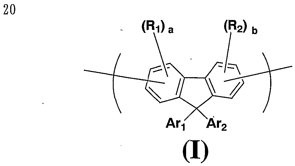
Claims

請求の範囲
1 . 下記式 (I ) で示される繰返し単位と下記式 (I I ) で示される繰返し単位とか らなる高分子化合物。
Figure imgf000046_0001
(I)
〔上記式 (I ) 中、 A および A r 2はそれぞれ独立に、 ァリール基または 1価の複素 環基を表し、 R,および R2はそれぞれ独立に、 アルキル基、 アルコキシ基、 アルキルチ ォ基、 ァリール基、 ァリールォキシ基、 ァリールチオ基、 ァリールアルキル基、 ァリー ルアルコキシ基、 ァリールアルキルチオ基、 ァリールアルケニル基、 ァリールアルキニ ル基、 アミノ基、 置換アミノ基、 シリル基、 置換シひル基、 ハロゲン原子、 ァシル基、 ァシルォキシ基、 ィミン残基、 アミド基、 酸イミド基、 1価の複素環基、 力ルポキシル 基、 置換力ルポキシル基、 シァノ基またはニトロ基を表し、 aおよび bはそれぞれ独立 に、 0〜3から選ばれる整数を表す。 および R2がそれぞれ複数個存在する場合、 そ れらは同一でも異なっていてもよい。 〕
Figure imgf000046_0002
〔上記式 (I I ) 中、 R5はアルキル基を表し、 R3および R4はそれぞれ独立に、 アル キル基、 アルコキシ基、 アルキルチオ基、 ァリール基、 ァリールォキシ基、 ァリールチ ォ基、 ァリールアルキル基、 ァリールアルコキシ基、 ァリールアルキルチオ基、 ァリー ルアルケニル基、 ァリールアルキニル基、 アミノ基、 置換アミノ基、 シリル基、 置換シ リル基、 ハロゲン原子、 ァシル基、 ァシルォキシ基、 ィミン残基、 アミド基、 酸イミド 基、 1価の複素環基、'力ルポキシル基、 置換力ルポキシル基、 シァノ基またはニトロ基 を表し、 cおよび dはそれぞれ独立に、 0〜 3から選ばれる整数を表す。 R3および R4 がそれぞれ複数個存在する場合、 それらは同一でも異なっていてもよい。 〕
2 . 上記式 (I ) で示される繰返し単位が、 下記式 (I I I ) で示される繰返し単位 である請求項 1記載の高分子化合物。
Figure imgf000047_0001
(ΙΠ)
〔上記式 (I I I ) 中、 A r 3および A r 4はそれぞれ独立に、 ァリール基または 1価の 複素環基を表し、 Rsおよび R7はそれぞれ独立に、 アルキル基、 アルコキシ基、 アルキ ルチオ基、 'ァリール基、 ァリールォキシ基、 ァリールチオ基、 ァリールアルキル基、 ァ リールアルコキシ基、 ァリールアルキルチオ基、 ァリールアルケニル基、 ァリールアル キニル基、 アミノ基、 置換アミノ基、 シリル基、 置換シリル基、 ハロゲン原子、 ァシル 基、 ァシルォキシ基、 ィミン残基、 アミド基、 酸イミド基、 1価の複素環基、 カルポキ シル基、 置換力ルポキシル基、 シァノ基またはニトロ基を表し、 eおよび fはそれぞれ 独立に、 0〜 3から選ばれる整数を表す。 R6および R7がそれぞれ複数個存在する場合 、 それらは同一でも異なっていてもよい。 〕
'
3 . 上記式 ( I I I ) 中、 A r 3および A r 4がそれぞれ独立に、 下記式 (I V) で示 される基である請求項 2記載の高分子ィヒ合物。
Figure imgf000047_0002
(IV)
〔上記式 (I V) 中、 R8はアルキル基、 アルコキシ基、 アルキルチオ基、 ァリール基 、 ァリールォキシ基、 ァリールチオ基、 ァリールアルキル基、 ァリールアルコキシ基、 ァリールアルキルチオ基、 ァリールアルケニル基、 ァリールアルキニル基、 アミノ基、 置換アミノ基、 シリル基、 置換シリル基、 ハロゲン原子、 ァシル基、 ァシルォキシ基、 ィミン残基、 アミド基、 酸イミド基、 1価の複素環基、 力ルポキシル基、 置換カルポキ シル基、 シァノ基またはニトロ基を表し、 gは 0〜 5から選ばれる整数を表す。 R8が 複数個存在する場合、 それらは同一でも異なっていてもよい。 〕
4 . 上記式 (I I I ) において eおよび fが 0であることを特徴とする請求項 2また は 3記載の高分子化合物。
5 . 上記式 (I I ) で示される繰返し単位が、 下記式 (V) で示される繰返し単位で ある請求項 1〜4のいずれか一項に記載の高分子ィ匕合物。
Figure imgf000048_0001
(V)
〔上記式 (V) 中、 Rnはアルキル基を表し、 R9および 。はそれぞれ独立に、 アル キル基、 アルコキシ基、 アルキルチオ基、 ァリール基、 ァリールォキシ基、 ァリールチ ォ基、 ァリールアルキル基、 ァリールアルコキシ基、 ァリールアルキルチオ基、 ァリー ルアルケニル基、 ァリールアルキニル基、 アミノ基、 置換アミノ基、 シリル基、 置換シ リル棊、 ハロゲン原子、 ァシル基、 ァシルォキシ基、 ィミン残基、 アミド基、 酸イミド 基、 1価の複素環基、 力ルポキシル基、 置換力ルポキシル基、 シァノ基またはニトロ基 を表し、 hおよび iはそれぞれ独立に、 0〜 3から選ばれる整数を表す。 R9および R | 0がそれぞれ複数個存在する場合、 それらは同一でも異なっていてもよい。 〕
6 . 上記式 (V) において hおよび iが 0である請求項 5記載の高分子化合物。
7 . ポリスチレン換算の数平均分子量が ¾. 0 3〜1 0 8である請求項 1〜6のいずれか 一項記載の高分子化合物。
8 . 正孔輸送材料、 電子輸送材料および発光材料からなる群から選ばれる少なくとも 1種類の材料と、 請求項 1〜 7のいずれか一項に記載の高分子ィヒ合物の少なくとも 1種 類とを含有する組成物。 '
9 - 請求項 1〜 7のいずれか一項に記載の高分子ィヒ合物を少なくとも 2種類含有する ことを特徴とする組成物。
1 0 . 陽極及び陰極からなる電極と、 該電極間に設けられ請求項 1〜7のいずれか一項 に記載の高分子化合物または請求項 8もしくは 9に記載の組成物を含む発光層とを有す る高分子発光素子。
1 1 . 請求項 1 0記載の高分子発光素子を含む面状光源。
1 2 . 請求項 1 0に記載の高分子発光素子を含む表示装置。
1 3 . 請求項 1〜 7のいずれか一項に記載の高分子化合物と溶媒とを含む液状組成物。 1 4 . 請求項 8または 9に記載の組成物と溶媒とを含む液状組成物。
1 5 . 請求項 1〜 7のいずれか一項に記載の高分子化合物または請求項 8もしくは 9に 記載の組成物を含む薄膜。
1 6 . 請求項 1〜 7のいずれか一項に記載の高分子化合物または請求項 8もしくは 9に 記載の組成物を含む有機トランジスタ。
1 7 . 請求項 1〜 7のいずれか一項に記載の高分子化合物または請求項 8もしくは 9に 記載の組成物を含む太陽電池。
PCT/JP2007/067688 2006-09-13 2007-09-05 Composé polymère et dispositif polymère émettant de la lumière Ceased WO2008032720A1 (fr)

Priority Applications (2)

Application Number Priority Date Filing Date Title
US12/439,706 US20090256475A1 (en) 2006-09-13 2007-09-05 Polymer compound and polymer light emitting device
EP07807097A EP2070965A4 (en) 2006-09-13 2007-09-05 Polymer compound and light-emitting polymer device

Applications Claiming Priority (2)

Application Number Priority Date Filing Date Title
JP2006247803 2006-09-13
JP2006-247803 2006-09-13

Publications (1)

Publication Number Publication Date
WO2008032720A1 true WO2008032720A1 (fr) 2008-03-20

Family

ID=39183777

Family Applications (1)

Application Number Title Priority Date Filing Date
PCT/JP2007/067688 Ceased WO2008032720A1 (fr) 2006-09-13 2007-09-05 Composé polymère et dispositif polymère émettant de la lumière

Country Status (6)

Country Link
US (1) US20090256475A1 (ja)
EP (1) EP2070965A4 (ja)
KR (1) KR20090053949A (ja)
CN (1) CN101511904A (ja)
TW (1) TW200825116A (ja)
WO (1) WO2008032720A1 (ja)

Cited By (6)

* Cited by examiner, † Cited by third party
Publication number Priority date Publication date Assignee Title
JP2009238708A (ja) * 2008-03-28 2009-10-15 Sumitomo Chemical Co Ltd 有機エレクトロルミネッセンス装置の製造方法
WO2010001982A1 (ja) * 2008-06-30 2010-01-07 住友化学株式会社 フェノキサジン系高分子化合物及びそれを用いた発光素子
US20110077373A1 (en) * 2009-09-29 2011-03-31 General Electric Company Polymer and optoelectronic device comprising the same
JP2011080066A (ja) * 2009-10-09 2011-04-21 Samsung Mobile Display Co Ltd 高分子及びこれを含む有機発光素子
JP2013133359A (ja) * 2011-12-26 2013-07-08 Sumitomo Chemical Co Ltd 高分子化合物およびそれを用いた有機el素子
JP2015506403A (ja) * 2012-01-31 2015-03-02 ケンブリッジ ディスプレイ テクノロジー リミテッド ポリマー

Families Citing this family (8)

* Cited by examiner, † Cited by third party
Publication number Priority date Publication date Assignee Title
JP5144938B2 (ja) * 2007-02-02 2013-02-13 住友化学株式会社 高分子発光素子、高分子化合物、組成物、液状組成物及び導電性薄膜
US20100207516A1 (en) * 2007-10-10 2010-08-19 Shota Moriwaki Polymer compound and polymer light-emitting device using the same
GB2454890B (en) * 2007-11-21 2010-08-25 Limited Cambridge Display Technology Light-emitting device and materials therefor
US8378338B2 (en) * 2007-11-30 2013-02-19 Sumitomo Chemical Company, Limited Conjugated compound, nitrogenated condensed-ring compound, nitrogenated condensed-ring polymer, organic thin film, and organic thin film element
KR101043047B1 (ko) * 2010-04-09 2011-06-21 경상대학교산학협력단 알콕시 나프탈렌기를 포함하는 새로운 유기태양전지 재료 및 이를 이용한 태양전지 소자
TWI518106B (zh) * 2010-12-21 2016-01-21 住友化學股份有限公司 具有碳簇構造之高分子化合物及使用該化合物之有機裝置
CN103547611B (zh) * 2011-03-25 2016-06-08 住友化学株式会社 高分子化合物和使用其形成的发光元件
KR102853991B1 (ko) * 2020-02-14 2025-09-03 경상국립대학교산학협력단 신규한 중합체 및 이를 이용하는 유기 전자 소자

Citations (16)

* Cited by examiner, † Cited by third party
Publication number Priority date Publication date Assignee Title
JPS5751781A (en) 1980-07-17 1982-03-26 Eastman Kodak Co Organic electroluminiscent cell and method
JPS59194393A (ja) 1983-03-25 1984-11-05 イ−ストマン コダツク カンパニ− 改良された電力転換効率をもつ有機エレクトロルミネツセント装置
JPS6370257A (ja) 1986-09-12 1988-03-30 Fuji Xerox Co Ltd 電子写真用電荷輸送材料
JPS63175860A (ja) 1987-01-16 1988-07-20 Fuji Xerox Co Ltd 電子写真感光体
JPH02135359A (ja) 1988-11-16 1990-05-24 Fuji Xerox Co Ltd 電子写真感光体
JPH02135361A (ja) 1988-11-16 1990-05-24 Fuji Xerox Co Ltd 電子写真感光体
JPH02209988A (ja) 1989-02-10 1990-08-21 Idemitsu Kosan Co Ltd 薄膜エレクトロルミネッセンス素子
JPH0337992A (ja) 1989-07-04 1991-02-19 Idemitsu Kosan Co Ltd 有機エレクトロルミネッセンス素子の製造方法
JPH03152184A (ja) 1989-11-08 1991-06-28 Nec Corp 有機薄膜el素子
JPH05110069A (ja) 1991-10-14 1993-04-30 Mitsubishi Electric Corp 電界効果トランジスタの製造方法
GB2300196A (en) 1995-04-10 1996-10-30 Sumitomo Chemical Co Polysilanes
JPH0945478A (ja) 1995-02-01 1997-02-14 Sumitomo Chem Co Ltd 高分子蛍光体とその製造方法および有機エレクトロルミネッセンス素子
WO2002045185A2 (de) 2000-12-01 2002-06-06 Fraunhofer-Gesellschaft zur Förderung der angewandten Forschung e.V. Breitbandig lichtemittierende polymere dioden (pled)
JP2003226744A (ja) * 2001-11-09 2003-08-12 Sumitomo Chem Co Ltd 高分子化合物およびそれを用いた高分子発光素子
WO2003095586A1 (en) 2002-05-10 2003-11-20 Cambridge Display Technology Limited Polymers their preparation and uses
WO2005049689A2 (en) * 2003-11-17 2005-06-02 Sumitomo Chemical Company, Limited Crosslinkable substituted fluorene compounds and conjugated oligomers or polymers based thereon

Family Cites Families (6)

* Cited by examiner, † Cited by third party
Publication number Priority date Publication date Assignee Title
TW511394B (en) * 2000-08-21 2002-11-21 Sumitomo Chemical Co Polymeric fluorescent substance and polymer light emitting device
TWI249542B (en) * 2001-11-09 2006-02-21 Sumitomo Chemical Co Polymer compound and polymer light-emitting device using the same
US6984461B2 (en) * 2002-06-21 2006-01-10 Samsung Sdi Co., Ltd. Blue electroluminescent polymer and organic-electroluminescent device using the same
GB0225869D0 (en) * 2002-11-06 2002-12-11 Cambridge Display Tech Ltd Polymer
US6916902B2 (en) * 2002-12-19 2005-07-12 Dow Global Technologies Inc. Tricyclic arylamine containing polymers and electronic devices therefrom
EP2048176A4 (en) * 2006-08-01 2010-04-28 Sumitomo Chemical Co Polymer compound and light-emitting polymer device

Patent Citations (16)

* Cited by examiner, † Cited by third party
Publication number Priority date Publication date Assignee Title
JPS5751781A (en) 1980-07-17 1982-03-26 Eastman Kodak Co Organic electroluminiscent cell and method
JPS59194393A (ja) 1983-03-25 1984-11-05 イ−ストマン コダツク カンパニ− 改良された電力転換効率をもつ有機エレクトロルミネツセント装置
JPS6370257A (ja) 1986-09-12 1988-03-30 Fuji Xerox Co Ltd 電子写真用電荷輸送材料
JPS63175860A (ja) 1987-01-16 1988-07-20 Fuji Xerox Co Ltd 電子写真感光体
JPH02135359A (ja) 1988-11-16 1990-05-24 Fuji Xerox Co Ltd 電子写真感光体
JPH02135361A (ja) 1988-11-16 1990-05-24 Fuji Xerox Co Ltd 電子写真感光体
JPH02209988A (ja) 1989-02-10 1990-08-21 Idemitsu Kosan Co Ltd 薄膜エレクトロルミネッセンス素子
JPH0337992A (ja) 1989-07-04 1991-02-19 Idemitsu Kosan Co Ltd 有機エレクトロルミネッセンス素子の製造方法
JPH03152184A (ja) 1989-11-08 1991-06-28 Nec Corp 有機薄膜el素子
JPH05110069A (ja) 1991-10-14 1993-04-30 Mitsubishi Electric Corp 電界効果トランジスタの製造方法
JPH0945478A (ja) 1995-02-01 1997-02-14 Sumitomo Chem Co Ltd 高分子蛍光体とその製造方法および有機エレクトロルミネッセンス素子
GB2300196A (en) 1995-04-10 1996-10-30 Sumitomo Chemical Co Polysilanes
WO2002045185A2 (de) 2000-12-01 2002-06-06 Fraunhofer-Gesellschaft zur Förderung der angewandten Forschung e.V. Breitbandig lichtemittierende polymere dioden (pled)
JP2003226744A (ja) * 2001-11-09 2003-08-12 Sumitomo Chem Co Ltd 高分子化合物およびそれを用いた高分子発光素子
WO2003095586A1 (en) 2002-05-10 2003-11-20 Cambridge Display Technology Limited Polymers their preparation and uses
WO2005049689A2 (en) * 2003-11-17 2005-06-02 Sumitomo Chemical Company, Limited Crosslinkable substituted fluorene compounds and conjugated oligomers or polymers based thereon

Non-Patent Citations (12)

* Cited by examiner, † Cited by third party
Title
"Organic Reactions", vol. 14, 1965, JOHN WILEY & SONS, INC., pages: 270 - 490
"Organic Syntheses", vol. VI, 1988, JOHN WILEY & SONS, INC., pages: 407 - 411
BERNIUS M.T. ET AL., ADVANCED MATERIALS, vol. 12, no. 23, 2000, pages 1737 - 1750, XP000977264 *
CHEM. REV., vol. 89, 1989, pages 1359
CHEM. REV., vol. 95, 1995, pages 2457
J. ORGANOMET. CHEM., vol. 576, 1999, pages 147
MACROMOLECULES, vol. 38, 2005, pages 7983 - 7991
MAKROMOL. CHEM., MACROMOL. SYMP., vol. 12, 1987, pages 229
SCIENCE, vol. 270, 1995, pages 1789
See also references of EP2070965A4
SYNTH. MET., vol. 102, 1999, pages 982
ZHU Y. ET AL., MACROMOLECULES, vol. 38, no. 19, 2005, pages 7983 - 7991, XP003021023 *

Cited By (8)

* Cited by examiner, † Cited by third party
Publication number Priority date Publication date Assignee Title
JP2009238708A (ja) * 2008-03-28 2009-10-15 Sumitomo Chemical Co Ltd 有機エレクトロルミネッセンス装置の製造方法
WO2010001982A1 (ja) * 2008-06-30 2010-01-07 住友化学株式会社 フェノキサジン系高分子化合物及びそれを用いた発光素子
JP2010031259A (ja) * 2008-06-30 2010-02-12 Sumitomo Chemical Co Ltd フェノキサジン系高分子化合物及びそれを用いた発光素子
US8476397B2 (en) 2008-06-30 2013-07-02 Sumitomo Chemical Company, Limited Phenoxazine polymer compound and light emitting device using the same
US20110077373A1 (en) * 2009-09-29 2011-03-31 General Electric Company Polymer and optoelectronic device comprising the same
JP2011080066A (ja) * 2009-10-09 2011-04-21 Samsung Mobile Display Co Ltd 高分子及びこれを含む有機発光素子
JP2013133359A (ja) * 2011-12-26 2013-07-08 Sumitomo Chemical Co Ltd 高分子化合物およびそれを用いた有機el素子
JP2015506403A (ja) * 2012-01-31 2015-03-02 ケンブリッジ ディスプレイ テクノロジー リミテッド ポリマー

Also Published As

Publication number Publication date
KR20090053949A (ko) 2009-05-28
US20090256475A1 (en) 2009-10-15
CN101511904A (zh) 2009-08-19
EP2070965A1 (en) 2009-06-17
TW200825116A (en) 2008-06-16
EP2070965A4 (en) 2010-11-10

Similar Documents

Publication Publication Date Title
JP5446079B2 (ja) 高分子化合物及びそれを用いた高分子発光素子
JP5625272B2 (ja) 1,3−ジエンを含む化合物及びその製造方法
JP5144938B2 (ja) 高分子発光素子、高分子化合物、組成物、液状組成物及び導電性薄膜
JP5281800B2 (ja) ブロック共重合体並びにそれを用いた組成物、液状組成物、発光性薄膜及び高分子発光素子
WO2008032720A1 (fr) Composé polymère et dispositif polymère émettant de la lumière
CN101516963B (zh) 高分子化合物和高分子发光元件
JP5281801B2 (ja) ブロック共重合体および高分子発光素子
JP2008208358A (ja) ブロック共重合体および高分子発光素子
WO2009151144A1 (ja) 共重合体及びそれを用いた高分子発光素子
WO2008038747A1 (en) Polymer compound and polymer light-emitting device using the same
JP2010215886A (ja) 高分子化合物及びそれを用いた発光素子
WO2006118345A1 (ja) 高分子化合物およびそれを用いた高分子発光素子
JP5251043B2 (ja) 高分子化合物および高分子発光素子
JP5407122B2 (ja) 高分子化合物および高分子発光素子
CN101675091A (zh) 高分子化合物以及含有它的组合物
JP2007119763A (ja) 高分子材料及び高分子発光素子
WO2013027656A1 (ja) 高分子化合物およびそれを用いた発光素子
JP5162868B2 (ja) 高分子発光素子及び有機トランジスタ並びにそれらに有用な組成物
JP4952032B2 (ja) 高分子発光素子及び有機トランジスタ並びにそれらに有用な組成物
JP5250961B2 (ja) 高分子発光素子及び有機トランジスタ並びにそれらに有用な組成物
JP5162856B2 (ja) 高分子発光素子及び有機トランジスタ並びにそれらに有用な組成物
JP5217361B2 (ja) 高分子化合物及びそれを用いた高分子発光素子
JP5239129B2 (ja) 高分子発光素子及び有機トランジスタ並びにそれらに有用な組成物
JP4952037B2 (ja) 高分子発光素子及び有機トランジスタ並びにそれらに有用な組成物
JP2012041537A (ja) 高分子発光素子及び有機トランジスタ並びにそれらに有用な組成物

Legal Events

Date Code Title Description
WWE Wipo information: entry into national phase

Ref document number: 200780033708.5

Country of ref document: CN

121 Ep: the epo has been informed by wipo that ep was designated in this application

Ref document number: 07807097

Country of ref document: EP

Kind code of ref document: A1

WWE Wipo information: entry into national phase

Ref document number: 2007807097

Country of ref document: EP

NENP Non-entry into the national phase

Ref country code: DE

WWE Wipo information: entry into national phase

Ref document number: 12439706

Country of ref document: US

WWE Wipo information: entry into national phase

Ref document number: 1020097007364

Country of ref document: KR