WO2009113189A1 - Décortiqueuse - Google Patents
Décortiqueuse Download PDFInfo
- Publication number
- WO2009113189A1 WO2009113189A1 PCT/JP2008/061946 JP2008061946W WO2009113189A1 WO 2009113189 A1 WO2009113189 A1 WO 2009113189A1 JP 2008061946 W JP2008061946 W JP 2008061946W WO 2009113189 A1 WO2009113189 A1 WO 2009113189A1
- Authority
- WO
- WIPO (PCT)
- Prior art keywords
- shaft
- roll
- supply plate
- link
- movable
- Prior art date
- Legal status (The legal status is an assumption and is not a legal conclusion. Google has not performed a legal analysis and makes no representation as to the accuracy of the status listed.)
- Ceased
Links
Images


Classifications
-
- B—PERFORMING OPERATIONS; TRANSPORTING
- B02—CRUSHING, PULVERISING, OR DISINTEGRATING; PREPARATORY TREATMENT OF GRAIN FOR MILLING
- B02B—PREPARING GRAIN FOR MILLING; REFINING GRANULAR FRUIT TO COMMERCIAL PRODUCTS BY WORKING THE SURFACE
- B02B3/00—Hulling; Husking; Decorticating; Polishing; Removing the awns; Degerming
- B02B3/04—Hulling; Husking; Decorticating; Polishing; Removing the awns; Degerming by means of rollers
- B02B3/045—Hulling; Husking; Decorticating; Polishing; Removing the awns; Degerming by means of rollers cooperating rollers
-
- B—PERFORMING OPERATIONS; TRANSPORTING
- B02—CRUSHING, PULVERISING, OR DISINTEGRATING; PREPARATORY TREATMENT OF GRAIN FOR MILLING
- B02B—PREPARING GRAIN FOR MILLING; REFINING GRANULAR FRUIT TO COMMERCIAL PRODUCTS BY WORKING THE SURFACE
- B02B7/00—Auxiliary devices
- B02B7/02—Feeding or discharging devices
Definitions
- the present invention relates to a hulling machine for hulling threshed grains.
- a pair of rolls disposed so as to be press-contactable with each other and a grain tank and a hopper disposed above the pair of rolls are provided, and the grains stored in the grain tank are transferred to the pair via the hopper.
- a rice huller is known that feeds between these rolls and grinds the grain sandwiched between the pair of rolls by the rotation of the pair of rolls.
- the contact position of the pair of rolls also changes, whereby the grain supply position supplied from the grain tank via the hopper Is displaced from the contact position of the pair of rolls, and the hulling efficiency is deteriorated.
- the following configuration has been proposed. That is, when supplying grain between the pair of rolls from the hopper, it is important to obtain a good hulling result that the grain is supplied as uniformly and regularly as possible. That is, it is important to accurately supply the grain flowing down through the hopper to the contact position of the pair of rolls.
- a supply plate is provided between the hopper and the pair of rolls, and the supply plate is manually positioned so that the tip of the supply plate faces the contact position of the pair of rolls.
- An adjustable configuration has been proposed.
- the grain supplied from the grain tank via the hopper is accurately adjusted by adjusting the position of the supply plate according to the wear of the pair of rolls.
- the position adjustment of the supply plate must be performed manually, and there is a problem that the position adjustment work of the supply plate becomes complicated.
- the hulling machine described in Patent Document 2 when the position adjustment operation of the supply plate is performed, the hulling work has to be interrupted, resulting in a problem that hulling work efficiency is poor.
- Patent Document 3 discloses a configuration in which the position of the supply plate disposed between the hopper and the pair of rolls can be automatically adjusted.
- the hulling machine described in Patent Document 3 includes a sensor that electrically detects the outer diameter of one of the pair of rolls, and the supply plate according to the roll diameter detected by the sensor. The position (tilt angle) is controlled.
- the hulling machine described in Patent Document 3 does not cause the problem in the hulling machine described in Patent Document 2, but controls the position of the supply plate based on the sensor or an electric signal detected by the sensor. Therefore, a control device is required to increase the number of parts, resulting in a problem that the device becomes complicated. Further, in the configuration described in Patent Document 3, when the outer surface of the pair of rolls is in a wavy state due to deterioration due to use or the like, the sensor detects the wavy state as the outer diameter of the roll, As a result, there may be a problem that stable position control of the supply plate cannot be performed. JP 56-28601 A JP 56-28601 A Japanese Patent Laid-Open No. 9-3133959
- the present invention has been made in view of the prior art, and is a hulling machine provided with a supply plate that guides grain to a contact position between a pair of rolls, and varies according to wear of the pair of rolls.
- An object of the present invention is to provide a hulling machine that can easily and stably follow the supply plate to the contact position of a pair of rolls.
- the present invention provides a fixed shaft that is driven to rotate about an axis by rotational power from a drive source, and an axis that is driven by rotational power from the drive source in a state substantially parallel to the fixed shaft.
- a grinder provided with a held supply plate, wherein the distal end portion of the supply plate is moved around the pivot shaft to the fixed shaft according to the amount of movement of the movable shaft support member close to the fixed shaft.
- a hulling machine provided with a link structure for rotating the pivot shaft around an axis by using the movement of the movable shaft support member so as to rotate in the approaching direction.
- the first and second rolls are always pressed against each other at a predetermined pressure by the pressing force of the pressing mechanism. That is, when the first and / or second roll is worn, the movable shaft support member is pushed by the push mechanism in a direction approaching the fixed shaft. Therefore, even if the first and / or second rolls are worn, the contact state of the first and second rolls under a predetermined pressure is maintained.
- the position of the contact portion varies depending on the degree of wear of the first and / or second rolls. That is, as wear of the first and / or second rolls proceeds, the contact portion is fixed from an initial position (that is, the position of the contact portion in a state before the first and second rolls are worn). Close to the axis.
- the supply plate is inclined such that the front end portion of the supply plate faces the contact portion regardless of the degree of wear of the first and / or second rolls.
- the movable shaft support member is moved in the direction closer to the fixed shaft by the pushing mechanism, and accordingly, the contact portion is also moved to the initial state.
- the link structure is configured such that the distal end portion of the supply plate rotates about the pivot shaft in a direction approaching the fixed shaft according to the amount of movement of the movable shaft support member close to the fixed shaft.
- the pivot shaft is rotated around the axis. Therefore, without providing a complicated structure such as a sensor for detecting the outer diameter of the first and / or second roll and an operating device for changing the inclination posture of the supply plate based on a detection signal from the sensor, The tilting posture of the supply plate can be surely followed by the change in position of the contact portion accompanying the wear of the first and / or second rolls, and the hulling work efficiency can be maintained well.
- the link structure is a state in which a fulcrum shaft disposed in parallel with the two shafts above the fixed shaft and the movable shaft, and a lower end side interposed between the fixed shaft and the movable shaft. So that the link arm swings around the fulcrum shaft in conjunction with the movement of the link arm supported relative to the fulcrum shaft so as not to rotate relative to the fixed shaft, and the movable shaft support member moving toward and away from the fixed shaft.
- a biasing member that operatively biases the link arm so that a lower end side of the link arm presses a side of the movable shaft support member facing the fixed shaft; and an axis around the fulcrum shaft by the link arm
- the movable shaft support member includes a base end portion rotatably supported around a rotation shaft disposed in parallel with the fixed shaft and the movable shaft, and a base end portion of the rotation shaft.
- An arm part extending radially outward with respect to the axis, a bearing provided on the arm so as to rotatably support the movable shaft, and a connecting part operatively connected to the push mechanism Can be provided.
- the bearing portion has a substantially arc-shaped outer peripheral surface centered on the axis of the movable shaft, and the lower end side of the link arm is provided on the outer peripheral surface of the bearing portion by the biasing member. Is pressed to the side facing the fixed shaft.
- the lower end side of the link arm is engaged with the portion having the substantially arc-shaped outer peripheral surface of the movable shaft support member, so that the first and / or second rolls can be worn.
- the movement of the movable shaft support member that rotates about the rotation shaft can be smoothly and accurately transmitted to the fulcrum shaft via the link arm. Therefore, it is possible to more reliably and stably follow the inclined posture of the supply plate with respect to the position change of the contact portion between both rolls caused by wear of the first and / or second rolls.
- the link mechanism includes a first link supported by the fulcrum shaft so as not to rotate relative to the fulcrum shaft, a second link supported by the pivot shaft so as not to rotate relative to the fulcrum shaft, and one end portion on the free end side of the first link. And an intermediate link connected to the free end side of the second link so as to be relatively rotatable. According to such a configuration, it is possible to improve the degree of design freedom regarding the arrangement of the fulcrum shaft and the pivot shaft. That is, the position of the fulcrum shaft is set so as to allow the link arm to move smoothly in conjunction with the movement of the movable shaft support member, and the feed plate receives the raw material cake flowing down from above.
- the pivot shaft can be rotated around the axis in conjunction with the rotation around the axis of the fulcrum shaft.
- the intermediate link is adjustable in length in the longitudinal direction. According to such a configuration, the inclination angle of the supply plate with respect to the inclination angle of the link arm can be changed by adjusting the length in the longitudinal direction of the intermediate link. Therefore, even after the link mechanism is assembled, the relative posture of the link arm and the supply plate can be adjusted easily and with high accuracy.
- the rice huller receives a raw material tank disposed above the first and second rolls, a supply shutter provided at a lower end opening of the raw material tank, and a raw material tank falling from the lower end opening.
- An upstream supply plate that spontaneously drops onto the supply plate; and a lead roller that can cooperate with the upstream supply plate to adjust the amount of raw material waste fed from the upstream supply plate to the supply plate. It can.
- the upstream supply plate is relatively unrotatable with respect to the upstream pivot shaft disposed in parallel with the pivot shaft above the pivot shaft so that the tilt direction is opposite to the tilt direction of the supply plate.
- the huller further includes an electric motor having an output shaft that extends in a direction orthogonal to the upstream pivot shaft and is driven to rotate about an axis, and a screw provided on an outer peripheral surface of the output shaft.
- a drive-side member having a threaded hole, the drive-side member extending in parallel with the upstream pivot shaft, and a base end side supported by the upstream pivot shaft in a relatively non-rotatable manner and on a free end side.
- a driven side member provided with an opening through which the drive side member is engaged, a tilt angle operation member that can be manually operated, and a control device that performs drive control of the electric motor based on an operation signal from the tilt angle operation member Can be provided.
- the opening is shaped to prevent the drive side member from rotating around the axis of the output shaft when the electric motor is driven.
- the controller is configured to operate the electric motor by an amount corresponding to an operation signal from the tilt angle operation member.
- the drive-side member extending and screwed to the output shaft tends to rotate about the axis of the output shaft.
- the drive side member is an opening of the driven side member whose base end is supported by the upstream pivot shaft so as not to be relatively rotatable, and the drive side member rotates about the axis of the output shaft.
- the drive-side member moves forward and backward along the axial direction of the output shaft without rotating around the axis of the output shaft.
- the upstream pivot shaft is rotated around the axis via the side member, and the inclination angle of the upstream supply plate changes.
- the inclination angle of the upstream supply plate can be accurately controlled by the operation control of the electric motor. That is, the distance between the upstream supply plate and the lead roller can be accurately adjusted using the electric motor in accordance with the amount of raw material sent from the raw material tank to the upstream supply plate. It becomes possible, and the raw material soot can be supplied from the upstream supply plate to the supply plate in a layered state.
- control device is configured to have a manual mode for controlling the electric motor based on an operation signal from the tilt angle operation member and an automatic mode for automatically controlling the electric motor.
- the control device sets a predetermined amount of a gap between the upstream supply plate and the lead roller based on signals from an upper limit sensor and a lower limit sensor of a tank in a sorter following the hulling machine.
- the electric motor is controlled to increase or decrease only.
- the link structure includes a restriction member that moves in conjunction with the movement of the movable shaft support member close to the fixed shaft, a distal end portion that is operatively connected to the restriction member, and a proximal end portion that is the pivot.
- a link rod supported on the support shaft so as not to rotate relative to the support shaft, and configured to rotate the pivot support shaft about the axis via the restricting member and the link rod by the movement of the movable shaft support member. .
- the restricting member moves the link rod in accordance with the movement of the movable shaft support member, the rotational direction around the axis of the pivot shaft fixes the tip of the supply plate around the pivot shaft.
- the movement of the link rod is regulated so that the rotation direction is such that it rotates in the direction close to the shaft.
- a complicated structure such as a sensor for detecting the outer diameter of the first and / or second rolls and an operating device for changing the inclination posture of the supply plate based on a detection signal from the sensor is provided. Without this, the tilting posture of the supply plate can be surely followed by the position change of the contact portion accompanying the wear of the first and / or second rolls, and the hulling work efficiency can be maintained well.
- the pivot shaft is disposed substantially immediately above the fixed shaft, and the link rod is bent so that a distal end portion thereof is close to the fixed shaft side around the pivot shaft with respect to a base end portion. .
- tip part of the said link rod operatively connected with the said limitation member has a big angle (angle near orthogonal) with respect to the said movement of the said movable shaft support member.
- the moving direction of the restricting member interlocked with the movable shaft support member and the moving direction of the tip end portion of the link rod when the link rod rotates around the pivot shaft are matched as much as possible.
- the supply plate can be rotated around the pivot shaft in a more linear relationship with the movement of the movable shaft support member. Therefore, the inclination posture of the supply plate can be made to follow the position change of the contact portion between the two rolls with higher accuracy.
- the restriction member is provided on the movable shaft support member. According to such a configuration, the restriction member can be interlocked with the movable shaft support member without providing a complicated structure.
- the restriction member has a lower surface portion having an engagement port into which a tip end portion of the link rod is engaged, and a pair of plane portions facing each other with the engagement port interposed therebetween, and the pair of plane surfaces
- One of the parts forms a side part that restricts the movement of the link rod on the upper end side.
- the link rod and the regulating member are connected by engaging the distal end portion of the link rod with the engagement port provided in the lower surface portion of the regulating member. It is possible to effectively prevent the link rod from dropping from the restricting member (releasing the connection relationship between the link rod and the restricting member). Moreover, in the said structure, connection with the said link rod and the said control member and control of the movement of the said link rod by the said control member are performed in another location. Therefore, both the connection and the regulation can be performed reliably and stably.
- the present invention also provides a first roll supported by the fixed shaft so as to rotate about the axis together with the fixed shaft, and a movable shaft that is substantially parallel to the fixed shaft and is capable of contacting and separating from the fixed shaft. And a second roll supported by the movable shaft so as to rotate about the axis, and the movable shaft is urged in a direction close to the fixed shaft so that the second roll is pressed against the first roll.
- a pushing mechanism a supply plate supported by a pivot shaft provided at a base end portion above the fixed shaft and the movable shaft and substantially parallel to the two shafts; and a base end portion at the pivot end.
- a hulling machine including a link rod supported by a support shaft so as not to rotate relative to the support shaft, and a restricting member for restricting movement of the link rod around the pivot shaft.
- the restricting member is configured such that the front end portion of the supply plate has the first roll and the The tip end portion of the link rod is locked against the biasing force so as to keep the state of facing the contact portion of the second roll.
- the locking position of the link rod around the pivot shaft is changed by moving the regulating member according to the movement of the movable shaft accompanying wear of the first roll and the second roll.
- the front end portion of the supply plate follows the position change of the contact portion due to wear of the first roll and the second roll.
- a complicated structure such as a sensor for detecting the outer diameter of the first and / or second rolls and an operating device for changing the inclination posture of the supply plate based on a detection signal from the sensor is provided. Without this, the tilting posture of the supply plate can be surely followed by the position change of the contact portion accompanying the wear of the first and / or second rolls, and the hulling work efficiency can be maintained well.
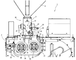
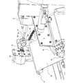
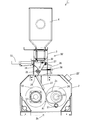
- FIG. 1 is a front view of the hulling machine according to the first embodiment of the present invention, and shows an initial state before the second roll in the hulling machine moves.
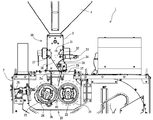
- FIG. 2 is a front view of the hulling machine in a state after the second roll has moved with wear of the first and second rolls in the hulling machine.
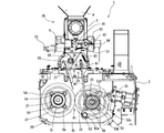
- FIG. 3 is a rear view of the hulling machine in the state shown in FIG.
- FIG. 4 is a rear view of the hulling machine in the state shown in FIG.
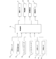
- FIG. 5 is a configuration block diagram of a control system of the hulling machine according to the first embodiment.
- FIG. 6 is a view showing a roll driving mechanism for driving the first and second rolls in the hulling machine according to the first embodiment.
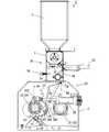
- FIG. 7 is an internal perspective view of the vicinity of the first and second rolls in the hulling machine according to the first embodiment.
- FIG. 8 is a perspective view of the vicinity of the tilt angle adjusting mechanism of the upstream supply plate in the huller according to the first embodiment.
- FIG. 9 is a schematic configuration diagram of an example of a hulling system to which the hulling machine according to the first embodiment is applied.
- FIG. 10 is a control flowchart of the maintenance mode in the hulling machine according to the first embodiment.
- FIG. 11 is a front view of a hulling machine according to a second embodiment of the present invention, and shows an initial state before the second roll in the hulling machine moves.
- FIG. 12 is a front view of the hulling machine according to the second embodiment, and shows a state after the second roll has moved.
- FIG. 13 is a rear view of the hulling machine in the state shown in FIG.
- FIG. 14 is a rear view of the hulling machine in the state shown in FIG.
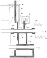
- FIG. 15 is a sectional view taken along line XV-XV in FIG.
- FIG. 16 is an enlarged cross-sectional view of a portion XVI in FIG.
- FIGS. 1 and 2 are front views of the huller 1 according to the first embodiment of the present invention
- FIGS. 3 and 4 are the hullers shown in FIG. 1 and FIG. 1 is a rear view of FIG.
- FIGS. 1 and 3 show a state before the second roll 24 described below in the huller 1 before moving (a state before the roll is worn), and
- FIGS. 2 shows a state after the roll 24 is moved (a state after the roll is worn).
- FIG. 5 is a block diagram showing the configuration of the control system of the hulling machine 1 according to the present embodiment
- FIG. 6 is a view showing a roll drive mechanism of the hulling machine 1 according to the present embodiment. is there.
- the huller 1 As shown in FIGS. 1 to 4, the huller 1 according to the present embodiment includes a machine frame 2 provided with openings 2a and 2b above and below, and an upper part provided at the upper opening 2a. It has a machine casing 3 and a raw material tank 4 provided above the upper machine casing 3 for storing raw material tanks.
- the hulling machine 1 further includes a hulling unit 20 that hulls the raw material hull and a supply unit 30 that supplies the raw material hull flowing down from the raw material hull tank 4 to the hulling unit 20.
- the upper machine casing 3 is provided with a supply port 31 that communicates between the lower end opening of the raw material tank 4 and the hulling portion 20 in the machine casing 2 inside the upper machine casing 3.
- the supply unit 30 is provided outside the upper machine casing 3 with a supply shutter 32 provided at the supply port 31, and opens and closes the supply shutter 32.
- the lead roller 35 disposed inside the upper machine casing 3 is supported so as to be rotatable in the direction along the inclination of the guide plate 34, and the grains are sequentially and quantitatively flowed down to the hulling portion 20.
- An impeller-like lead roller 35 and an upstream supply whose upper end is rotatably supported around the upstream pivot shaft 37 in a state where the guide plate 34 is opposed to the guide roller 34 in a funnel shape.
- said upstream And a said lead roller 35 can be adjusted the gap between the upstream side supply plate 36 by rotating the pivot shaft 37 around.
- the lead roller 35 is configured to be able to adjust the amount of raw material waste fed from the upstream supply plate 36 to a supply plate 27 described later in cooperation with the upstream supply plate 36.
- an electric motor is used as the opening / closing drive unit 33.
- the supply shutter 32 is connected to a shaft that moves forward and backward by the electric motor, and the supply shutter 32 opens and closes the supply port 31 by controlling the driving of the electric motor.
- the hulling portion 20 includes a fixed shaft 21 that is rotationally driven at a first rotational speed around an axis by rotational power from an electric motor 6 that is a drive source, A movable shaft 23 whose position can be changed so as to be able to contact and separate from the fixed shaft 21 in a state substantially parallel to the fixed shaft 21, and the first rotational speed around the axis by the rotational power from the electric motor 6.
- the movable so as to be pressed at a predetermined pressure And a pressing mechanism 25 for directly or indirectly push the 23.
- the hulling machine 1 includes a pivot shaft 26 disposed in parallel with the two shafts above the fixed shaft 21 and the movable shaft 23, and a raw material cake fed from above the first roll 22. And the supply plate 27 supported on the pivot shaft 26 so as not to rotate relative to the contact portion A1 of the second roll 24. The supply plate 27 is supported by the pivot shaft 26 so as not to be relatively rotatable so that the inclination direction is opposite to the inclination direction of the upstream supply plate 36.
- the hulling machine 1 includes a work switch 71 that performs ON / OFF switching of the hulling work by the first roll 22 and the second roll 24, and an operation signal from the work switch 71. And a control device 70 for controlling the electric motor 6 and the push mechanism 25 based on the above.
- the control device 70 includes a calculation unit and a storage unit (both not shown), and is configured to control the hulling machine 1 based on a program stored in the storage unit.
- the control device 70 is a microcomputer mounted on an electric circuit in the hulling machine 1 or an external computer electrically connected to the hulling machine 1.
- the driving force of the electric motor 6 provided outside the machine frame 2 is transmitted to the first roll 22 and the second roll 24 via a pulley / belt transmission mechanism.
- they are rotationally driven in opposite directions and at different rotational speeds.
- the pulley / belt transmission mechanism includes a pulley 611 supported by the output shaft 61 of the electric motor 6 in a relatively non-rotatable manner, a pulley 211 supported by the fixed shaft 21 in a relatively non-rotatable manner, and the movable shaft. 23, a pulley 231 supported so as not to rotate relative to the pulley 23, a driving belt 621 wound around the pulley 611 and the pulley 211, and a driving belt 623 wound around the pulley 211 and the pulley 231. .
- the pulley 211 is a first pulley around which the drive belt 621 is wound and a second pulley around which the drive belt 623 is wound, and has a diameter different from that of the first pulley.
- the second pulley is included, so that the rotational speeds of the fixed shaft 21 and the movable shaft 23 are made different.
- the drive belt 623 is also wound around a direction changing pulley so that the rotation direction of the movable shaft 23 is different from the rotation direction of the fixed shaft 21.
- the lead roller 35 is also rotated in the direction in which the raw material cake is introduced into the hulling portion 20 by the driving force from the same electric motor 6 via the driving belt.
- the huller 1 includes a tension roller 612 that applies / releases tension to the drive belt 621, and the control device 70 responds to the operation of the work switch 71.
- the position of the tension roller 612 is controlled so that the 612 applies / releases tension to the drive belt 621, so that the driving force of the electric motor 6 is applied to the first roll 22 and the second roll 24. It is comprised so that it may transmit / block to.
- the huller 1 As shown in FIG. 3, the huller 1 according to the present embodiment has a fixed shaft support member 51 that supports the fixed shaft 21 so as to be rotatable about an axis via a bearing, and the fixed shaft support member 51 is fixed to the machine casing 2.
- FIG. 7 shows an internal perspective view of the vicinity of the roll in the huller 1 according to the present embodiment.
- the huller 1 has a movable shaft support member 53 that supports the movable shaft 23 through a bearing so as to be rotatable about an axis.
- the movable shaft support member 53 includes a base end portion 53a that is rotatably supported around a rotation shaft 52 disposed in parallel with the movable shaft 23, and an axis line of the rotation shaft 52 from the base end portion 53a.
- the arm portion 53b extending radially outward with respect to the reference, the bearing portion 53c provided on the arm portion 53b so as to rotatably support the movable shaft 23, and the push mechanism 25 are operatively connected. And a connecting portion 53d. Accordingly, when the bearing portion 53 c rotates about the rotation shaft 52, the second roll 24 also rotates about the rotation shaft 52.
- the pushing mechanism 25 has one end connected to the machine casing 2 and the other end connected to the connecting portion 53 d, and the second roll 24 is in a direction approaching the first roll 22.
- the movable shaft support member 53 is pushed around the rotation shaft, whereby the rolls 22 and 24 are pressed against each other.
- one end of the pushing mechanism 25 is fixed to the side surface of the machine frame 2 on the second roll 24 side.
- an air cylinder is used as the push mechanism 25, but the present invention is not limited to such a configuration, and for example, an electric motor can be used as the push mechanism 25.
- the base end portion 53a and the connecting portion 53d are arranged on the opposite sides in the radial direction with respect to the movable shaft 23. According to such a configuration, the movable shaft support member 53 is supported from both sides with the movable shaft 23 interposed therebetween, so that the support of the second roll 24 can be stabilized.
- the supply plate 27 includes a base end portion that is supported by the pivot shaft 26 so as not to be relatively rotatable, and a tip end that extends from the base end portion toward the contact portion A1 of the pair of first and second rolls 22 and 24.
- the pivot shaft 26 is located above the first and second rolls 22 and 24, more specifically, closer to the fixed shaft 21 than the contact portion A1 of the first and second rolls. 21 and the movable shaft 23 are arranged so as to have an axis substantially parallel.
- the supply plate 27 is supported at its base end portion so as not to rotate relative to the pivot shaft 26, and its front end portion from the base end portion to the contact portion A1 of the pair of first and second rolls 22, 24.
- the raw material basket slides down on the surface of the supply plate 27 on the second roll 24 side.
- the hulling machine 1 has the movable shaft so that the inclination angle of the supply plate 27 changes following the movement of the movable shaft support member 53 to and away from the fixed shaft 21.
- a link structure for operatively connecting the support member 53 and the pivot shaft 26 is provided.
- the link structure includes a fulcrum shaft 41 disposed in parallel with the two shafts above the fixed shaft 21 and the movable shaft 23, and a lower end side between the fixed shaft 21 and the movable shaft 23.
- a link arm 42 that is supported by the fulcrum shaft 41 so as not to rotate relative to the fulcrum shaft 41, and the link arm 42 in conjunction with the movement of the movable shaft support member 53 coming into and out of contact with the fixed shaft 21.
- the link arm 42 is operatively biased so that the lower end side of the link arm 42 presses the side of the movable shaft support member 53 facing the fixed shaft 21 such that the link arm 42 swings around the fulcrum shaft 41.
- the fulcrum shaft 41 and the pivot shaft 26 are operated so that the pivot shaft 26 rotates about the axis in response to the rotation of the fulcrum member 43 and the link arm 42 about the axis line of the fulcrum shaft 41.
- the link structure follows the movement of the movable shaft support member 53 in contact with and away from the fixed shaft 21, and the inclination angle of the supply plate 27 is the link arm 42, the fulcrum shaft 41, the link It is configured to change via the mechanism 44 and the pivot shaft 26.
- the link mechanism 44 includes a first link 441 that is supported so as not to rotate relative to the fulcrum shaft 41, a second link 442 that is supported so as not to rotate relative to the pivot shaft 26, and one end portion.
- the intermediate link 443 is connected to the free end side of the first link 441 so as to be relatively rotatable, and the other end portion is connected to the free end side of the second link 442 so as to be relatively rotatable.
- the bearing portion 53 c has a substantially arc-shaped outer peripheral surface centered on the axis of the movable shaft 23, and the lower end side of the link arm 42 is an outer peripheral surface of the bearing portion 53 c by the biasing member 43. It is comprised so that it may be pressed by the side facing the said fixed axis
- the control device 70 operates the electric motor 6 to cause the first roll 22, the second roll 24, and the lead roller 35 to operate. And the opening / closing drive unit 33 is driven to open the supply shutter 32. As a result, the raw material waste stored in the raw material waste tank 4 falls into the supply unit 30. The dropped raw material cake slides down a flow path formed by the guide plate 34 and the upstream supply plate 36 located below, and is supplied to the lead roller 35.
- the raw material fed supplied to the lead roller 35 is rotated in the machine frame 2 in a uniform layer state according to the size of the gap between the lead roller 35 and the upstream supply plate 36 by the rotation of the lead roller 35. Are sequentially and quantitatively supplied to the hulling unit 20.
- the control device 70 In response to the ON operation of the work switch 71, the control device 70 further operates the push mechanism 25. As a result, the second roll 24 rotates about the rotation shaft 52 and moves in the direction approaching the first roll 22.
- the movable shaft support member 53 is rotated about the rotation shaft 52 by the push mechanism 25 operatively connected to the connection portion 53d, whereby the bearing portion 53c rotates about the axis.
- the movable shaft 23 that is freely supported also moves around the rotation shaft 52 in a direction close to the fixed shaft 21. As a result, a contact portion A1 is formed between the first roll 22 and the second roll 24, in which the first roll 22 and the second roll are pressed against each other with a predetermined pressure.
- the raw material rice cake supplied from the supply unit 30 slides down the surface of the supply plate 27 (the surface on the second roll 24 side), and the first roll 22 to which the front end portion of the supply plate 27 is directed and the It is supplied to the contact portion A1 between the second rolls 24.
- the first roll 22 and the second roll 24 are in a state where the second roll 24 is pressed against the first roll 22 by the push mechanism 25 via the movable shaft support member 53 with a predetermined pressure.
- the rotating power from the electric motor 6 rotates at different rotational speeds. For this reason, the raw material rice cake supplied to the contact portion A1 by the supply plate 27 is subjected to a scouring process by the first and second rolls 22 and 24 and is discharged from the lower opening 2b.
- the raw material koji discharged from the lower opening 2b is sorted into grain and chaff crushed by a sorting mechanism such as a wind sorting device (not shown).
- the first roll 22 and / or the second roll 24 wear from the state shown in FIGS. 1 and 3 due to continuous use, and the outer diameter becomes smaller as shown in FIGS. 2 and 4, the first and second rolls 22 and 24 in the state before wear shown in FIGS. 1 and 3 are indicated by broken lines), and the pushing mechanism 25 Due to the urging force, the second roll 24 is rotated around the rotation shaft 52 in a direction approaching the first roll 22 (FIGS. 2 and 4), whereby the first roll 22 and the The pressure contact state of both rolls is maintained in a state where the position of the contact portion A1 between the second rolls 24 is changed.
- the supply plate 27 operates on the fulcrum shaft 41 disposed in parallel with the two shafts above the fixed shaft 21 and the movable shaft 23 via the pivot shaft 26 and the link mechanism 44. It is connected.
- the fulcrum shaft 41 further supports the base end portion of the link arm 42 so as not to be relatively rotatable.
- the link arm 42 has a lower end interposed between the fixed shaft 21 and the movable shaft 23 and faces the fixed shaft 21 in the movable shaft support member 53 by the biasing force of the biasing member 43.
- the upper end side is supported by the fulcrum shaft 41 so as not to be relatively rotatable while being pressed to the side. That is, the lower end side of the link arm 42 is always in contact with the side of the movable shaft support member 53 facing the fixed shaft 21 by the biasing force of the biasing member 43.
- the movable shaft support member 53 is rotated around the rotation shaft 52 by the push mechanism 25 in the direction in which the movable shaft 23 approaches the fixed shaft 21 according to wear of the first and second rolls 22, 24.
- the link arm 42 swings around the fulcrum shaft 41 against the urging force of the urging member 43, and the fulcrum shaft 41 rotates around the axis.
- the pivot shaft 26 rotates about the axis via the link mechanism 44, whereby the inclination angle of the supply plate 27 changes.
- the first link of the link mechanism 44 supported by the fulcrum shaft 41 so as not to be relatively rotatable. 441 also rotates around the fulcrum shaft 41.
- the second link 442 supported by the pivot shaft 26 so as not to rotate relative to the pivot shaft 26 rotates around the pivot shaft 26 via the intermediate link 443.
- the pivot shaft 26 rotates around the axis.
- the supply plate 27 whose upper end is supported by the pivot shaft 26 so as not to rotate relative to the pivot shaft 26 swings around the pivot shaft 26, thereby The inclination angle of the supply plate 27 changes.
- the second roll 24 is pushed by the pushing mechanism 25 due to wear of the first and / or second rolls 22 and 24.
- the supply plate 27 rotates around the pivot shaft 26 via the link arm 42, the fulcrum shaft 41, the link mechanism 44, and the pivot shaft 26, thereby the supply plate 27.
- the inclination posture of the supply plate 27 is automatically changed so that the front end portion thereof follows the contact portion A1 whose position changes due to the movement of the second roll 24.
- a sensor that detects the outer diameter of the first and / or second rolls 22 and 24 and a control that changes the inclined posture of the supply plate 27 based on the sensor.
- the tip of the supply plate 27 follows the contact portion A1 between the two rolls 22 and 24 whose position changes according to wear of the first roll 22 and / or the second roll 24.
- the inclination posture of the supply plate 27 is automatically adjusted. Therefore, the follow-up operation of the supply plate 27 to the contact position of the pair of rolls 22 and 24 that varies according to the wear of the pair of first and second rolls 22 and 24 can be performed easily and stably. it can. As a result, the hulling efficiency by the first roll 22 and the second roll 24 can be favorably maintained.
- the outer peripheral surface of the bearing portion 53 c of the movable shaft support member 53 has a substantially arc shape centered on the axis of the movable shaft 23. That is, the link arm 42 urged toward the side of the bearing portion 53c facing the fixed shaft 21 by the urging force of the urging member 43 is formed on the outer peripheral surface of the bearing portion 53c having a substantially arc shape. Point contact.
- the movement of the movable shaft support member 53 that rotates about the rotation shaft 52 in accordance with the wear of the first roll 22 and / or the second roll 24 is transmitted via the link arm 42.
- the fulcrum shaft 41 can be transmitted smoothly and accurately. Accordingly, the posture of the supply plate 27 is stably followed with respect to the position change of the contact portion A1 between the two rolls 22 and 24 caused by the wear of the first roll 22 and / or the second roll 24. Can be made.
- the first link 441 and the second link 442 are connected by the intermediate link 443.
- the arrangement of the fulcrum shaft 41 and the pivot shaft 26 can be freely set. Therefore, the design freedom of the link arm 42 and the supply plate 27 can be improved. Thereby, the operation of the supply plate 27 accompanying the movement of the movable shaft 23 can be performed more smoothly.
- the intermediate link 443 can be adjusted in length in the longitudinal direction.
- the intermediate link 443 is a first member that forms one end side, a second member that forms the other end side, and an adjustment member that connects the first and second members. And an adjusting member having a thread portion screwed into the first and second members along the direction.
- the intermediate link 443 adjustable in length in the longitudinal direction, the swing angle of the supply plate 27 with respect to the swing angle of the link arm 42 can be easily adjusted. Therefore, even after the link mechanism 44 is assembled, the inclination posture of the supply plate 27 can be adjusted more accurately and easily by finely adjusting the length of the intermediate link 443 in the longitudinal direction. .
- the huller 1 according to the present embodiment is configured such that the gap between the upstream supply plate 36 and the lead roller 35 can be adjusted electrically.
- FIG. 8 shows a perspective view of the vicinity of the upstream supply plate 36 in the huller 1 according to the present embodiment.
- the hulling machine 1 is an electric motor (adjustment motor) having an output shaft 81 that extends in a direction orthogonal to the upstream pivot shaft 37 and is driven to rotate about an axis.
- the control device 70 controls the drive of the adjustment motor 8 so as to operate the adjustment motor 8 by an amount corresponding to an operation signal from the inclination angle operation member 72. Is supposed to do.
- the opening 83 a of the driven side member 83 prevents the drive side member 82 from rotating around the axis of the output shaft 81 when the adjustment motor 8 is driven, thereby allowing the drive side member 82 to be rotated. It has a shape that moves in the axial direction of the output shaft 81, thereby allowing the driven member 82 to rotate around the upstream pivot shaft 37.
- the opening 83a has a long hole shape that is long in a direction along a virtual line connecting the rotation axis of the upstream pivot shaft 37 and the axis of the drive side member 82.
- the upstream supply plate 36 is biased in a direction approaching the lead roller 35 by a biasing member 38 attached to the driven member 83.
- the gap between the upstream supply plate 36 and the lead roller 35 is performed as follows.
- the control device 70 operates the adjustment motor 8 by an amount corresponding to an operation signal from the tilt angle operation member 72.
- the output shaft 81 extending in a direction orthogonal to the upstream pivot shaft 37 rotates around the axis.
- the output shaft 81 Since the screw 81a provided on the outer peripheral surface of the output shaft 81 is screwed into the threaded hole 82a of the drive side member 82 extending in parallel with the upstream pivot shaft 37, the output shaft 81 The drive side member 82 tries to rotate around the axis of the output shaft 81 according to the rotation around the axis. However, the drive-side member 82 is engaged with the opening 83a of the driven-side member 83 whose base end is supported on the upstream pivot shaft 37 so as not to be relatively rotatable. Since the opening 83a has a long hole shape that prevents the drive-side member 82 from rotating about the axis of the output shaft 81, the output shaft 81 of the adjustment motor 8 is rotated about the axis.
- the drive side member 82 moves back and forth along the axial direction of the output shaft 81. Then, when the drive side member 82 moves back and forth along the axial direction of the output shaft 81, the driven side member 83 engaged with the drive side member 82 through the opening 83 a is urged. It swings around the upstream pivot shaft 37 against the biasing force of the member 38.
- the drive side member 82 moves back and forth in the axial direction of the output shaft 81 in accordance with the drive of the adjustment motor 8, so that the driven side member 83 rotates around the upstream pivot shaft 37.
- the inclination angle of the upstream supply plate 36 can be accurately controlled by the operation control of the adjustment motor 8.
- the distance between the upstream supply plate 36 and the lead roller 35 can be accurately adjusted according to the amount of raw material sent from the raw material tank 4 to the upstream supply plate 36.
- the raw material soot can be supplied from the upstream supply plate 36 to the supply plate 27 in a fixed layer state.
- the huller 1 further includes a rotary encoder 84 that detects the rotation angle of the output shaft 81, and the control device 70 is configured to adjust the adjustment motor based on the detection amount of the rotary encoder 84. 8 is controlled.
- the control device 70 stores in advance rotation speed data (relationship between operation time and rotation angle) of the adjustment motor 8, and rotates the adjustment motor 8 for a predetermined time. By driving, the adjustment motor 8 may be operated by an amount corresponding to the operation signal from the tilt angle operation member 71.
- FIG. 9 shows a schematic configuration diagram of an example of a hulling system to which the hulling machine according to the present embodiment is applied.
- the hulling machine 1 constitutes a hulling system together with a succeeding sorter (swinging sorter) 10.
- the hulling system is configured to perform the sorting operation in the sorting machine 10 continuously on the result of the hulling work and the wind sorting work performed by the hulling machine 1.
- a sorter charging elevator 13 for interposing the resultant product is interposed between the lower opening 1b of the huller 1 and the upper opening 10a of the tank of the sorter 10.
- control device 70 automatically controls the adjustment motor 8 based on an operation signal from the tilt angle operation member 72 and the adjustment motor 8 automatically. And an automatic mode to control.
- control device 70 may be configured to activate the manual mode when the tilt angle operation member 72 is manually operated. In the manual mode, the control device 70 controls the adjustment motor 8 based on an operation signal from the tilt angle operation member 72.
- the control device 70 can be configured to control the adjustment motor 8 based on the hulling work speed by the hulling machine 1 and the sorting work speed by the sorting machine 10.
- the control device 70 controls the adjusting motor 8 according to the storage amount of the tank 14 in the sorting machine 10 following the hulling machine 1 in the automatic mode. It can be configured to control.
- an upper limit sensor 11 and a lower limit sensor 12 are provided in the tank 14, and the control device 70 sets a gap between the upstream supply plate 36 and the lead roller 35 based on signals from the sensors 11 and 12.
- the adjustment motor 8 may be controlled so as to increase or decrease by a fixed amount.
- control device 70 is based on detection signals from the upper limit sensor 11 and the lower limit sensor 12. It can also be configured to activate the automatic mode.
- the control device 70 may not output a control signal for the adjustment motor 8 (that is, The gap between the upstream supply plate 36 and the lead roller 35 is maintained).
- the control device 70 may perform control to delay the hulling work speed of the huller 1 from the normal state. That is, the control device 70 controls the adjustment motor 8 so that the gap between the upstream supply plate 36 and the lead roller 35 is narrowed by a predetermined amount with reference to a normal state.
- the control device 70 controls the adjustment motor 8 so that the gap between the upstream supply plate 36 and the lead roller 35 is widened by a predetermined amount with reference to the normal state. In this way, by performing feedback control of the adjustment motor 8 using the grain storage state in the process subsequent to the hulling machine 1, work efficiency of the whole hulling system including the hulling machine 1 is improved. be able to.
- the control device 70 may have a maintenance mode that is activated based on an external operation. Specifically, in the maintenance mode, the control device 70 stops the driving of the electric motor 6 so that the second roll 24 is pressed against the first roll 22 while the driving mechanism 25 is pressed. Is activated.
- the huller 1 includes a maintenance switch 73 for activating the maintenance mode.
- the maintenance switch 73 is provided, for example, outside the machine casing 2.
- FIG. 10 shows a control flowchart in the maintenance mode.
- the first roll 22 is fixed to the fixed shaft 21 via the mounting screw 54 screwed in the axial direction of the fixed shaft 21.
- the second roll 24 is fixed to the movable shaft 23 via the mounting screw 54 screwed in the axial direction of the movable shaft 23.
- the control device 70 operates the electric motor 6 to rotationally drive the fixed shaft 21 and the movable shaft 23, and the first roll A hulling operation mode for controlling the operation of the pushing mechanism 25 so that the pressure between the second roll 24 and the second roll 24 becomes a predetermined value is executed.
- the first roll 22 and the second roll 24 are removed from the electric motor 6 in a state where the second roll 24 is pressed against the first roll 22 through the push mechanism 25 with a predetermined pressure. It rotates at different rotational speeds depending on the rotational power.
- the control device 70 performs the following control. That is, as shown in FIG. 10, the control device 70 operates the maintenance switch 73 (Yes in step S1), and the first roll 22 and the second roll 24 are in a rotation drive stopped state (step S3). In the maintenance mode, the control device 70 operates the push mechanism 25 in a state in which the rotation drive of the first roll 22 and the second roll 24 by the electric motor 6 is stopped, and thus the second roll. 24 is pressed against the first roll 22. When the control device 70 detects that the maintenance switch 73 is operated again (Yes in step S4), the control device 70 releases the pressure between the first roll 22 and the second roll 24 by the push mechanism 25 ( Step S5).
- the first roll 22 and the second roll 24 are in pressure contact with each other with the rotation of the first roll 22 and the second roll 24 stopped. .
- the work of tightening and loosening the mounting screw 54 can be performed very easily.
- the mounting screw 54 screwed in the axial direction of the fixed shaft 21 and / or the movable shaft 23 is loosened or It is necessary to perform the tightening work.
- the mounting screw 54 is loosened and / or tightened. If it does so, the fixed shaft 21 and / or the movable shaft will rotate around the axis, and the efficiency of the work of loosening and / or tightening the mounting screw 54 will deteriorate.
- the first roll 22 and the second roll 24 are pressed against each other with the rotation of the first roll 22 and the second roll 24 stopped. It is in the state.
- this maintenance mode when the mounting screw 54 is loosened to remove one of the corresponding rolls from one of the fixed shaft 21 and the movable shaft 23, it is supported by the other of the fixed shaft 21 and the movable shaft 23. The other roll prevents rotation of the one roll. Therefore, when the mounting screw 54 is loosened and / or tightened, the fixed shaft 21 or the movable shaft 23 can be prevented from rotating together. Thereby, the attachment / detachment work efficiency of the first and / or second rolls 22 and 24 can be improved without providing a dedicated tool or a dedicated structure.
- the push mechanism 25 is operated so that the second roll 24 is pressed against the first roll 22 at the same pressure as the predetermined pressure during the hulling operation in the maintenance mode. That is, the pushing operation of the pushing mechanism 25 in the maintenance mode can be made the same as the pushing operation of the pushing mechanism 25 in the hulling operation.
- Such a configuration is particularly effective when an air cylinder is used as the pushing mechanism 25 as in the huller 1 according to the present embodiment. That is, when an air cylinder is used as the pushing mechanism 25, the pushing operation of the pushing mechanism 25 during the maintenance mode is different from the pushing operation of the pushing mechanism 25 during the hulling operation.
- the control device 70 may have a different control flow, or a structure for limiting or increasing the push operation of the push mechanism 25 is required.
- the pressing force between the first and second rolls 22 and 24 by the pressing mechanism 25 during the hulling operation is the same as the rotation of the fixed shaft 21 and the movable shaft 23 when the mounting screw 54 is loosened and tightened. Has sufficient pressure to prevent Therefore, by making the pushing operation of the pushing mechanism 25 during the maintenance mode the same as the pushing operation of the pushing mechanism 25 during the hulling work, the first member can be used without substantially adding an additional member. And the removal
- the pressure between the first roll 22 and the second roll 24 is controlled by current value control for the electric motor.
- the current value when the gap between the first roll 22 and the second roll 24 becomes 0 can be adopted as the set current value in the maintenance mode.
- the control device 70 is configured not to shift to the maintenance mode when the first roll 22 and the second roll 24 are rotationally driven. That is, during the hulling operation, the control device 70 does not activate the maintenance mode even if the maintenance switch 73 is operated. According to such a configuration, even if the maintenance switch 73 is erroneously operated during the hulling operation, the rotation drive of the first roll 22 and the second roll 24 is not stopped, so that the hulling failure due to the erroneous operation is prevented. Can be prevented.
- the maintenance switch 73 may be configured to be inoperable by a regulating member or the like during the hulling operation.
- step S6 when the first roll 22 and the second roll 24 are driven to rotate during the operation of the maintenance switch 73 (No in step S2), an error is notified by sound or a lamp (step S6). It is also possible to configure. Further, in addition to the above control mode, it is preferable that the shift to the hulling operation mode is not performed during the maintenance mode. That is, in the maintenance mode, the control device 70 is configured not to activate the hulling work mode even if the work switch 71 is turned on.
- the adjustment of the inclination angle of the upstream supply plate 36 is electrically performed using the adjustment motor 8, but the present invention is not limited to such a form. It is also possible to adjust the inclination angle of the upstream supply plate 36 manually.
- a manually operable adjustment screw having a distal end abutting on the back surface of the upstream supply plate 36 and a base end extending outside the upper machine casing 3 is provided, and the upstream supply is provided by the adjustment screw. It is also possible to adjust the inclination angle of the plate 36.
- FIGS. 11 and 12 are front views of a hulling machine 1 ′ according to the second embodiment of the present invention.
- FIGS. 13 and 14 show the hulling machine shown in FIGS. It is a rear view of machine 1 '. 11 and 13 show a state before the second roll 24 is moved in the huller 1 (a state before the roll is worn), and
- FIGS. 12 and 14 show the second roll. 24 shows a state after movement (a state after the roll is worn).
- FIG. 15 is a sectional view of the huller 1 ′ taken along the line XV-XV in FIG.
- the same members as those in the first embodiment are denoted by the same reference numerals, and the description thereof is omitted as appropriate.
- the hulling machine 1 ′ also has the machine frame 2 and the upper machine frame 3 as shown in FIGS. And the raw material tank 4. Furthermore, the rice huller 1 ′ includes a hulling unit 20 ′ that crushes the raw material hull, and a supply unit 30 ′ that supplies the raw material hull flowing down from the raw material hull tank 4 to the hulling unit 20 ′. ing.
- the supply unit 30 ′ includes the supply shutter 32 provided in the supply port 31 of the upper machine casing 3, the opening / closing drive unit 33, and the guide plate 34.
- the lead roller 35 and the upstream supply plate 36 are provided.
- the upstream supply plate 36 is configured so that the inclination posture is manually changed.
- the supply portion 30 ′ has a distal end portion that abuts against the back surface of the upstream supply plate 36 and a base end portion that acts as a grip portion extends to the outside of the upper machine casing 3.
- An adjustment screw 38 is provided, and the rotation angle (inclination posture) of the upstream supply plate 36 is changed by changing the amount of the adjustment screw 38 entering the upper machine casing 3 using the grip portion. It is supposed to be.
- an electric motor is used as the opening / closing drive unit 33.
- the hulling portion 20 ′ is similar to the hulling portion 20 in the first embodiment.
- the fixed shaft 21 and the first shaft supported by the fixed shaft 21 are the same.
- a roll 22, the movable shaft 23, the second roll 24 supported by the movable shaft 23, the pushing mechanism 25, the pivot shaft 26, and the supply plate 27 are provided.
- the hulling portion 20 ′ further includes the movable shaft 23 and the pivotal support so that the inclination angle of the supply plate 27 changes following the movement of the movable shaft 23 moving toward and away from the fixed shaft 21.
- a link structure for operatively connecting the shaft 26 is provided.
- the link structure includes a regulating member 28 (FIGS. 13 and 14) that moves according to the movement of the second roll 24, a distal end portion that is operatively connected to the regulating member 28, and a proximal end. And a link rod 29 (FIGS. 13 and 14) supported by the pivot shaft 26 so as not to rotate relative to the pivot shaft 26.
- the regulating member 28 is configured so that the leading end of the supply plate 27 is positioned toward the contact portion A1 between the first roll 22 and the second roll 24 according to the movement of the second roll 24. The movement of the rod 29 is controlled.
- the first roll 22 and the second roll 24 are driven by a drive belt (not shown) provided on a drive source (not shown) provided outside the machine frame 2 so as to rotate in opposite directions and at different peripheral speeds. (Not shown).
- a pulley 231 (see FIG. 15) supported so as not to rotate relative to the movable shaft 23, a pulley (not shown) supported so as not to rotate relative to the fixed shaft 21, and an output shaft of the drive source.
- Each of the rolls 22 and 24 is rotationally driven by hanging the drive belt around a pulley (not shown) supported so as not to rotate.
- the pulley 231 fixed to the movable shaft 23 and the pulley diameter of the pulley fixed to the fixed shaft 21 are made different from each other, so that the first roll 22 and the second roll using a common power source.
- the rotation speed of the roll 24 can be varied.
- the lead roller 35 is also rotated in the direction of introducing the raw material cake into the hulling portion 20 ′ by the driving force from the same driving source via the driving belt.
- the huller 1 ′ is further a boss member (movable shaft support member) 52 that rotatably supports the movable shaft 23 around its axis
- a boss member (movable shaft support member) 52 that rotates together with the movable shaft 23 around a rotation shaft 51 that is substantially parallel to the shaft 23 is provided.
- the boss member 52 includes a bearing holding portion 521 that supports the movable shaft 23 through a bearing 232 so as to be rotatable about an axis.
- the boss member 52 rotates about the rotation shaft 51
- the movable shaft 23 and the second roll 24 supported by the movable shaft 23 also rotate about the rotation shaft 51.
- there are allowable openings 2 c that allow the boss member 52 to rotate about the rotation shaft 51 on the front surface and the back surface of the machine frame 2. Is provided.
- One end of the pushing mechanism 25 is connected to the machine casing 2 and the other end is connected to the boss member 52, and the boss member 52 is moved in the direction in which the second roll 24 is close to the first roll 22. Is pushed around the rotation shaft 51, whereby the rolls 22 and 24 are pressed against each other.
- one end of the pushing mechanism 25 is fixed to the side surface of the machine frame 2 on the first roll 22 side.
- an air cylinder is used as the push mechanism 25.
- the present invention is not limited to such a configuration, and for example, an electric motor may be used as the push mechanism 25.
- the boss member 52 has a fixed portion 522 on the side opposite to the rotating shaft 51 with respect to the movable shaft 23, and the other end portion of the push mechanism 25 is the fixed portion 522. It is connected to. According to such a configuration, the boss member 52 is supported from both sides with the movable shaft 23 interposed therebetween, and accordingly, the support of the second roll 24 can be stabilized.
- the supply plate 27 is supported at the base end portion thereof on the pivot shaft 26 positioned above the first roll 22 and the second roll 24 so as not to rotate relative to the supply plate 27, and the distal end portion thereof is supported by the pair of base ends. It extends toward the contact portion A1 of the first and second rolls 22 and 24, so that the raw material rice cake slides on the surface of the supply plate 27 on the second roll 24 side.
- the pivot shaft 26 is disposed substantially parallel to the movable shaft 23 at a position directly above the fixed shaft 21 and at the end of the upper opening 2a on the fixed shaft 21 side.
- the link rod 29 is supported by the pivot shaft 26 so that the base end portion thereof cannot rotate relative to the link rod 29. Accordingly, the supply plate 27 rotates about the pivot shaft 26 in accordance with the rotation of the link rod 29 about the pivot shaft 26.
- one end of the pivot shaft 26 extends outward from the machine frame 2, and the base end of the link rod 29 is located outside the machine frame 2. On the other hand, it is supported on the pivot shaft 26 so as not to be relatively rotatable.
- the restricting member 28 is configured to move around the rotating shaft 51 together with the second roll 24 by the push mechanism 25.
- the distal end portion of the link rod 29 is locked to the restriction member 28 that moves according to the movement of the second roll 24. That is, when the second roll 24 is rotated about the rotation shaft 51 by the push mechanism 25, the restricting member 28 is also rotated about the rotation shaft 51, thereby the link rod 29.
- the slanting posture is changed.
- the supply plate 27 and the link rod 29 are located on the side close to the contact portion A1 with respect to a virtual vertical plane B2 passing through the axis of the pivot shaft 26, and The tip end portion of the link rod 29 is locked to the regulating member 28 in such a state that it is inclined such that it swings around the pivot shaft 26 in a direction approaching the virtual vertical plane B2 by its own weight.
- the restricting member 28 has a direction in which the supply plate 27 and the link rod 29 supported by the pivot shaft 26 so as not to rotate relative to each other are close to the virtual vertical plane B2 due to their own weight (the axis of the pivot shaft 26).
- One direction of rotation hereinafter, engaged with the link rod 29 so as to restrict the movement to swing about the pivot shaft 26 in the own weight swing direction C1 (refer to FIG. 13).
- the front end portion of the supply plate 27 follows the change in the position of the second roll 24 and automatically goes to the contact portion A1. That is, the boss member 52 is rotated around the rotation shaft 51 by the pushing mechanism 25, and thereby the second roll 24 is rotated in a direction close to the first roll 22.
- the restriction member 28 is also close to the first roll 22.
- the restricting member 28 is operatively connected to the boss member 52. In the present embodiment, as shown in FIGS. 13 to 15, the restricting member 28 is supported by the boss member 52 and the first roll about the rotation shaft 51 together with the second roll 24. It moves in the direction approaching the roll 22.
- the regulating member 28 is supported by the boss member 52.
- the restricting member 28 is provided on a plate portion 523 located outside the machine casing 2 in the boss member 52.
- FIG. 16 shows an enlarged cross-sectional view of the portion XVI in FIG.
- the restricting member 28 has a stop portion that stops the movement of the link rod 29 in the self-weight swinging direction C1.
- the regulating member 28 is substantially sandwiched between the lower surface portion 282 having an engagement port 281 into which the tip end portion of the link rod 29 is engaged and the engagement port 281.
- a pair of plane portions that extend in the vertical direction and face each other, and one of the pair of plane portions functions as a stop portion that stops the swinging of the link rod 29 in the own-weight swinging direction C1. 283 is formed.
- the restriction member 28 has a bottom plate and a peripheral wall extending upward from a peripheral portion of the bottom plate, and has a cylindrical shape with the top opened.
- the bottom plate is formed with the engagement port 281, and the bottom plate forms the lower surface portion 282.
- a side surface of the peripheral wall that is close to the first roll 22 forms the side surface portion 283.
- the link rod 29, the restriction member 28, and the link rod 29 are inserted into the engagement inlet 281 provided in the lower surface portion 282 of the restriction member 28. (That is, the link rod 29 is prevented from falling off from the regulating member 28). Further, the upper end side of the side surface portion 283 of the restricting member 28 functions as the stop portion, and the swinging of the link rod 29 in the self-weight swinging direction C1 is restricted. Details will be described later.
- the restricting member 28 has a cylindrical shape with the bottom plate and the peripheral wall having an open top, but the present invention is not limited to such a form. That is, the restricting member 28 can be formed by a flat plate member having only the bottom plate on which the engagement port 281 is formed. In such a replacement mode, a portion of the inner peripheral surface of the engagement inlet 281 located on the pivot shaft 26 side acts as the stop portion.
- the supply plate 27 is configured such that the second roll 24 is pressed against the first roll 22 by the push mechanism 25 and the link rod 29 is swung in the self-weight swing direction C1 by the restriction member 28.
- the base end portion is supported on the pivot shaft 26 so as not to be relatively rotatable so that the tip end portion faces the contact portion A1 between the rolls 22 and 24.
- the supply shutter 32 is opened by the opening / closing drive unit 33 in a state where the drive unit is operated to rotate the first roll 22, the second roll 24, and the lead roller 35.
- the raw material waste stored in the raw material waste tank 4 falls downward from the supply port 31.
- the dropped raw material cake slides down a flow path formed by the guide plate 34 and the upstream supply plate 36 located below, and is supplied to the lead roller 35.
- the raw material supplied to the lead roller 35 is rotated in the machine frame 2 through the upper opening 2 a according to the size of the gap between the lead roller 35 and the upstream supply plate 36 due to the rotation of the lead roller 35.
- the upstream supply plate 36 is rotated around the upstream pivot shaft 37 using the adjustment screw 38.
- the inclination angle of the upstream supply plate 36 is changed, and the size of the gap between the lead roller 35 and the upstream supply plate 36 is changed.
- the raw material supplied from the supply unit 30 ′ slides down the surface of the supply plate 27 (the surface on the second roll 24 side) located below the lower opening 2 a, and the leading end of the supply plate 27 Is supplied to the contact portion A ⁇ b> 1 of the first roll 22 and the second roll 24.
- the raw material rice cake is subjected to a hulling process and discharged from the lower opening 2b.
- a wind sorting device or the like (not shown) is arranged to sort the crushed grain and rice husk.
- the second roll 24 is constantly pushed toward the first roll 22 by the pushing mechanism 25. Accordingly, when the outer diameters of the first roll 22 and the second roll 24 are worn and reduced from the state shown in FIG. 11, the second roll 24 is It is moved around the rotation shaft 51 in a direction approaching the first roll 22 (FIG. 12). That is, when the first and / or second rolls 22 and 24 are worn, the position of the contact portion A1 is maintained while the first and second rolls 22 and 24 are kept in pressure contact with each other at the contact portion A1. Change.
- the second roll 24 moves in response to wear of the first and / or second rolls 22 and 24 (that is, when the contact portion A1 changes from the initial position), the second roll 24 is
- the regulating member 28 provided on the boss member 52 to be supported also rotates around the rotation shaft 51 together with the second roll 24.
- the link rod 29 whose base end portion is supported by the pivot shaft 26 so as not to rotate relative to the pivot shaft 26 is in an inclined posture such that the link rod 29 swings in the self-weight swinging direction C1 by its own weight, and the distal end portion is the engagement port.
- An intermediate portion between the distal end portion and the proximal end portion is engaged with the stop portion.
- the link rod 29 corresponds to the amount of rotation of the restricting member 28. Is pivoted around the pivot shaft 26 in a direction approaching the fixed shaft 21, whereby the pivot shaft 26 is pivoted about the axis line, so that the supply plate 27 is also pivoted around the pivot shaft 26. It rotates in the direction close to the fixed shaft 21 (FIG. 14).
- the restricting member 28 changes the position of the link rod 29 around the pivot shaft 26 according to a change in the relative position of the movable shaft 23 with respect to the fixed shaft 21.
- the state in which the tip end portion of the supply plate 27 faces the contact portion A1 of the first roll 22 and the second roll 24 is maintained.
- the link rod 29 is separated from the upper end of the side surface portion 283 of the regulating member 28 and comes into contact with the end portion of the engagement port 281, whereby the self-weight swing direction C ⁇ b> 1.
- the swinging to is restricted.
- the hulling machine 1 ′ is configured such that the first and second rolls 22, 22 are urged in the direction in which the second roll 24 approaches the first roll 22.
- the regulation member 28 and the supply plate 27 that move according to the movement of the second roll 24 are interposed via the link rod 29.
- the supply plate 27 is rotated by an amount corresponding to the movement of the second roll 24, and the front end portion of the supply plate 27 automatically faces the contact portion A1.
- the link rod 29 is bent so that the tip end portion is close to the fixed shaft 21 side around the pivot shaft 26 with respect to the base end portion.
- the link rod 29 includes a base end side straight portion including the base end portion that is supported relatively non-rotatably on the pivot shaft 26, and a tip end side including the tip portion engaged with the restriction member 29.
- the distal end side linear portion is bent from the base end side linear portion in a direction approaching the fixed shaft 21.
- the link rod 29 is bent between the distal end portion and the proximal end portion so that the distal end portion is close to the fixed shaft 21 side around the pivot shaft 26 with respect to the proximal end portion.
- the link rod 29 has a distal end-side straight portion on one side around the pivot shaft 26 (on the basis of an imaginary line B1 obtained by extending the proximal-end straight portion (see above). It is bent so as to be located on the arrow C1 side which is the fixed shaft 21 side.
- the link rod 29 in a bent shape, the distal end side straight portion including the distal end portion of the link rod 29 engaged with the restriction member 28 and the moving direction of the second roll 24 (The intersection angle with the rotation direction around the rotation shaft 51 can be increased (an angle close to 90 degrees).
- the intersection angle with the rotation direction around the rotation shaft 51 can be increased (an angle close to 90 degrees).
- the moving direction of the tip of the link rod can be matched as much as possible, and the supply plate 27 can be rotated more linearly with respect to the movement of the second roll 24. Therefore, the tip of the supply plate 27 can be made to follow the position change of the contact portion A1 between the rolls 22 and 24 with higher accuracy.
Landscapes
- Adjustment And Processing Of Grains (AREA)
Abstract
Priority Applications (2)
| Application Number | Priority Date | Filing Date | Title |
|---|---|---|---|
| US12/922,223 US8596193B2 (en) | 2008-03-14 | 2008-07-02 | Grain huller |
| CN2008801279645A CN101970116B (zh) | 2008-03-14 | 2008-07-02 | 脱壳机 |
Applications Claiming Priority (2)
| Application Number | Priority Date | Filing Date | Title |
|---|---|---|---|
| JP2008-065738 | 2008-03-14 | ||
| JP2008065738A JP5041540B2 (ja) | 2008-03-14 | 2008-03-14 | 籾摺機 |
Publications (1)
| Publication Number | Publication Date |
|---|---|
| WO2009113189A1 true WO2009113189A1 (fr) | 2009-09-17 |
Family
ID=41064869
Family Applications (1)
| Application Number | Title | Priority Date | Filing Date |
|---|---|---|---|
| PCT/JP2008/061946 Ceased WO2009113189A1 (fr) | 2008-03-14 | 2008-07-02 | Décortiqueuse |
Country Status (4)
| Country | Link |
|---|---|
| US (1) | US8596193B2 (fr) |
| JP (1) | JP5041540B2 (fr) |
| CN (1) | CN101970116B (fr) |
| WO (1) | WO2009113189A1 (fr) |
Cited By (3)
| Publication number | Priority date | Publication date | Assignee | Title |
|---|---|---|---|---|
| KR101545822B1 (ko) | 2014-11-07 | 2015-08-19 | 주식회사 명진 | 곡물의 탈피 장치 |
| JP2018020293A (ja) * | 2016-08-04 | 2018-02-08 | 株式会社サタケ | 籾摺機 |
| CN108525730A (zh) * | 2018-04-17 | 2018-09-14 | 武汉轻工大学 | 基于杨辉三角的颗粒流分流装置 |
Families Citing this family (10)
| Publication number | Priority date | Publication date | Assignee | Title |
|---|---|---|---|---|
| USD681063S1 (en) * | 2011-06-03 | 2013-04-30 | Satake Corporation | Optical grain sorter |
| US9629390B1 (en) * | 2013-01-26 | 2017-04-25 | Turner Innovations Ltd. | Sorrel harvesting machine with spaced apart rotating return and cutting drums moving in opposite directions at a throat therebetween |
| JP2014208321A (ja) * | 2013-04-16 | 2014-11-06 | 株式会社サタケ | 籾摺機 |
| CN106111236B (zh) * | 2016-03-25 | 2023-06-23 | 天门仙粮机械有限公司 | 家用小型粮食加工机械自动砻谷联动调节机构 |
| JP1577250S (fr) * | 2016-09-08 | 2017-05-29 | ||
| JP1605315S (fr) * | 2017-10-05 | 2018-06-04 | ||
| JP1621637S (fr) * | 2018-02-09 | 2019-01-07 | ||
| CN112774763B (zh) * | 2021-02-04 | 2022-04-05 | 浙江粮工机械科技有限公司 | 一种双变频电机的砻谷机 |
| JP7665474B2 (ja) * | 2021-08-31 | 2025-04-21 | 日本車輌製造株式会社 | 籾摺装置 |
| CN114917983A (zh) * | 2022-02-13 | 2022-08-19 | 浙江齐鲤机械有限公司 | 一种砻谷机下料补偿系统 |
Citations (5)
| Publication number | Priority date | Publication date | Assignee | Title |
|---|---|---|---|---|
| JPS5628601A (en) * | 1979-07-10 | 1981-03-20 | Salete Garces Felipe | Riceecleaning machine using cereal grain conveyance by gas feeding |
| JPH05337382A (ja) * | 1992-06-09 | 1993-12-21 | Kubota Corp | ロール式籾摺装置 |
| JPH07222932A (ja) * | 1994-02-14 | 1995-08-22 | Kubota Corp | 籾摺機 |
| JPH09122510A (ja) * | 1995-11-02 | 1997-05-13 | Satake Eng Co Ltd | 脱ぷ装置 |
| US20040261635A1 (en) * | 2003-06-25 | 2004-12-30 | Buhler Ag | Roller-sheller for cereals |
Family Cites Families (4)
| Publication number | Priority date | Publication date | Assignee | Title |
|---|---|---|---|---|
| US3952645A (en) * | 1974-12-02 | 1976-04-27 | Toshihiko Satake | Grain hulling and sorting apparatus |
| JPS57171447A (en) * | 1981-04-13 | 1982-10-22 | Yanmar Agricult Equip | Gluten removing device for rice hulling |
| JPH1033997A (ja) * | 1996-07-22 | 1998-02-10 | Satake Eng Co Ltd | 脱ぷ装置 |
| JPH09313959A (ja) | 1996-05-23 | 1997-12-09 | Satake Eng Co Ltd | 脱ぷ装置 |
-
2008
- 2008-03-14 JP JP2008065738A patent/JP5041540B2/ja not_active Expired - Fee Related
- 2008-07-02 WO PCT/JP2008/061946 patent/WO2009113189A1/fr not_active Ceased
- 2008-07-02 US US12/922,223 patent/US8596193B2/en not_active Expired - Fee Related
- 2008-07-02 CN CN2008801279645A patent/CN101970116B/zh not_active Expired - Fee Related
Patent Citations (5)
| Publication number | Priority date | Publication date | Assignee | Title |
|---|---|---|---|---|
| JPS5628601A (en) * | 1979-07-10 | 1981-03-20 | Salete Garces Felipe | Riceecleaning machine using cereal grain conveyance by gas feeding |
| JPH05337382A (ja) * | 1992-06-09 | 1993-12-21 | Kubota Corp | ロール式籾摺装置 |
| JPH07222932A (ja) * | 1994-02-14 | 1995-08-22 | Kubota Corp | 籾摺機 |
| JPH09122510A (ja) * | 1995-11-02 | 1997-05-13 | Satake Eng Co Ltd | 脱ぷ装置 |
| US20040261635A1 (en) * | 2003-06-25 | 2004-12-30 | Buhler Ag | Roller-sheller for cereals |
Cited By (5)
| Publication number | Priority date | Publication date | Assignee | Title |
|---|---|---|---|---|
| KR101545822B1 (ko) | 2014-11-07 | 2015-08-19 | 주식회사 명진 | 곡물의 탈피 장치 |
| JP2018020293A (ja) * | 2016-08-04 | 2018-02-08 | 株式会社サタケ | 籾摺機 |
| WO2018025604A1 (fr) * | 2016-08-04 | 2018-02-08 | 株式会社サタケ | Décortiqueuse |
| CN108525730A (zh) * | 2018-04-17 | 2018-09-14 | 武汉轻工大学 | 基于杨辉三角的颗粒流分流装置 |
| CN108525730B (zh) * | 2018-04-17 | 2023-08-18 | 武汉轻工大学 | 基于杨辉三角的颗粒流分流装置 |
Also Published As
| Publication number | Publication date |
|---|---|
| JP2009219983A (ja) | 2009-10-01 |
| JP5041540B2 (ja) | 2012-10-03 |
| US20110192291A1 (en) | 2011-08-11 |
| CN101970116B (zh) | 2013-02-13 |
| US8596193B2 (en) | 2013-12-03 |
| CN101970116A (zh) | 2011-02-09 |
Similar Documents
| Publication | Publication Date | Title |
|---|---|---|
| WO2009113189A1 (fr) | Décortiqueuse | |
| EP0820814B1 (fr) | Appareil de décorticage à cylindres comportant un dispositif de guidage incliné | |
| EP0771590B1 (fr) | Appareil de décorticage | |
| JP4513107B2 (ja) | 脱ぷ装置 | |
| JP4863402B2 (ja) | 籾摺機 | |
| JP4863401B2 (ja) | 籾摺機 | |
| JP6198451B2 (ja) | 脱穀装置 | |
| JP2009106883A (ja) | 籾摺選別装置 | |
| JP2009255001A (ja) | 籾摺機 | |
| JPH09313959A (ja) | 脱ぷ装置 | |
| CN114602578B (zh) | 一种三辊砻谷装置 | |
| JP4683561B2 (ja) | 脱ぷ装置 | |
| JP5185583B2 (ja) | 脱ぷ装置 | |
| JP5690622B2 (ja) | 脱穀装置 | |
| JP2023151300A (ja) | 脱穀装置 | |
| JP2008100172A (ja) | 脱ぷ装置 | |
| JP2012143169A (ja) | 脱穀装置 | |
| JP7665474B2 (ja) | 籾摺装置 | |
| JP2010081812A (ja) | 脱穀装置 | |
| SU152607A1 (fr) | ||
| JPH05168959A (ja) | 籾摺機のロール摩耗警報装置 | |
| JP3020768B2 (ja) | ロール式籾摺装置 | |
| JP2004305793A (ja) | 籾摺機のロール間隙調整装置およびロール間隙調整方法 | |
| JP2025129488A (ja) | 原料の受け渡し装置 | |
| JP2023034736A (ja) | 籾摺装置 |
Legal Events
| Date | Code | Title | Description |
|---|---|---|---|
| WWE | Wipo information: entry into national phase |
Ref document number: 200880127964.5 Country of ref document: CN |
|
| 121 | Ep: the epo has been informed by wipo that ep was designated in this application |
Ref document number: 08790797 Country of ref document: EP Kind code of ref document: A1 |
|
| NENP | Non-entry into the national phase |
Ref country code: DE |
|
| WWE | Wipo information: entry into national phase |
Ref document number: 12922223 Country of ref document: US |
|
| 122 | Ep: pct application non-entry in european phase |
Ref document number: 08790797 Country of ref document: EP Kind code of ref document: A1 |