WO2010146691A1 - 車両の制御装置 - Google Patents
車両の制御装置 Download PDFInfo
- Publication number
- WO2010146691A1 WO2010146691A1 PCT/JP2009/061109 JP2009061109W WO2010146691A1 WO 2010146691 A1 WO2010146691 A1 WO 2010146691A1 JP 2009061109 W JP2009061109 W JP 2009061109W WO 2010146691 A1 WO2010146691 A1 WO 2010146691A1
- Authority
- WO
- WIPO (PCT)
- Prior art keywords
- heat
- control
- heat source
- amount
- generation amount
- Prior art date
- Legal status (The legal status is an assumption and is not a legal conclusion. Google has not performed a legal analysis and makes no representation as to the accuracy of the status listed.)
- Ceased
Links
Images


Classifications
-
- F—MECHANICAL ENGINEERING; LIGHTING; HEATING; WEAPONS; BLASTING
- F02—COMBUSTION ENGINES; HOT-GAS OR COMBUSTION-PRODUCT ENGINE PLANTS
- F02D—CONTROLLING COMBUSTION ENGINES
- F02D29/00—Controlling engines, such controlling being peculiar to the devices driven thereby, the devices being other than parts or accessories essential to engine operation, e.g. controlling of engines by signals external thereto
- F02D29/04—Controlling engines, such controlling being peculiar to the devices driven thereby, the devices being other than parts or accessories essential to engine operation, e.g. controlling of engines by signals external thereto peculiar to engines driving pumps
-
- F—MECHANICAL ENGINEERING; LIGHTING; HEATING; WEAPONS; BLASTING
- F02—COMBUSTION ENGINES; HOT-GAS OR COMBUSTION-PRODUCT ENGINE PLANTS
- F02D—CONTROLLING COMBUSTION ENGINES
- F02D13/00—Controlling the engine output power by varying inlet or exhaust valve operating characteristics, e.g. timing
- F02D13/02—Controlling the engine output power by varying inlet or exhaust valve operating characteristics, e.g. timing during engine operation
- F02D13/0242—Variable control of the exhaust valves only
- F02D13/0249—Variable control of the exhaust valves only changing the valve timing only
-
- F—MECHANICAL ENGINEERING; LIGHTING; HEATING; WEAPONS; BLASTING
- F02—COMBUSTION ENGINES; HOT-GAS OR COMBUSTION-PRODUCT ENGINE PLANTS
- F02D—CONTROLLING COMBUSTION ENGINES
- F02D41/00—Electrical control of supply of combustible mixture or its constituents
- F02D41/02—Circuit arrangements for generating control signals
- F02D41/021—Introducing corrections for particular conditions exterior to the engine
-
- F—MECHANICAL ENGINEERING; LIGHTING; HEATING; WEAPONS; BLASTING
- F02—COMBUSTION ENGINES; HOT-GAS OR COMBUSTION-PRODUCT ENGINE PLANTS
- F02P—IGNITION, OTHER THAN COMPRESSION IGNITION, FOR INTERNAL-COMBUSTION ENGINES; TESTING OF IGNITION TIMING IN COMPRESSION-IGNITION ENGINES
- F02P5/00—Advancing or retarding ignition; Control therefor
- F02P5/04—Advancing or retarding ignition; Control therefor automatically, as a function of the working conditions of the engine or vehicle or of the atmospheric conditions
- F02P5/145—Advancing or retarding ignition; Control therefor automatically, as a function of the working conditions of the engine or vehicle or of the atmospheric conditions using electrical means
- F02P5/15—Digital data processing
- F02P5/1502—Digital data processing using one central computing unit
-
- F—MECHANICAL ENGINEERING; LIGHTING; HEATING; WEAPONS; BLASTING
- F01—MACHINES OR ENGINES IN GENERAL; ENGINE PLANTS IN GENERAL; STEAM ENGINES
- F01P—COOLING OF MACHINES OR ENGINES IN GENERAL; COOLING OF INTERNAL-COMBUSTION ENGINES
- F01P3/00—Liquid cooling
- F01P3/02—Arrangements for cooling cylinders or cylinder heads
- F01P2003/028—Cooling cylinders and cylinder heads in series
-
- F—MECHANICAL ENGINEERING; LIGHTING; HEATING; WEAPONS; BLASTING
- F01—MACHINES OR ENGINES IN GENERAL; ENGINE PLANTS IN GENERAL; STEAM ENGINES
- F01P—COOLING OF MACHINES OR ENGINES IN GENERAL; COOLING OF INTERNAL-COMBUSTION ENGINES
- F01P2060/00—Cooling circuits using auxiliaries
- F01P2060/04—Lubricant cooler
-
- F—MECHANICAL ENGINEERING; LIGHTING; HEATING; WEAPONS; BLASTING
- F01—MACHINES OR ENGINES IN GENERAL; ENGINE PLANTS IN GENERAL; STEAM ENGINES
- F01P—COOLING OF MACHINES OR ENGINES IN GENERAL; COOLING OF INTERNAL-COMBUSTION ENGINES
- F01P2060/00—Cooling circuits using auxiliaries
- F01P2060/08—Cabin heater
-
- F—MECHANICAL ENGINEERING; LIGHTING; HEATING; WEAPONS; BLASTING
- F02—COMBUSTION ENGINES; HOT-GAS OR COMBUSTION-PRODUCT ENGINE PLANTS
- F02D—CONTROLLING COMBUSTION ENGINES
- F02D41/00—Electrical control of supply of combustible mixture or its constituents
- F02D41/0002—Controlling intake air
- F02D2041/001—Controlling intake air for engines with variable valve actuation
-
- F—MECHANICAL ENGINEERING; LIGHTING; HEATING; WEAPONS; BLASTING
- F02—COMBUSTION ENGINES; HOT-GAS OR COMBUSTION-PRODUCT ENGINE PLANTS
- F02D—CONTROLLING COMBUSTION ENGINES
- F02D2200/00—Input parameters for engine control
- F02D2200/02—Input parameters for engine control the parameters being related to the engine
- F02D2200/021—Engine temperature
- F02D2200/022—Estimation of engine temperature
-
- Y—GENERAL TAGGING OF NEW TECHNOLOGICAL DEVELOPMENTS; GENERAL TAGGING OF CROSS-SECTIONAL TECHNOLOGIES SPANNING OVER SEVERAL SECTIONS OF THE IPC; TECHNICAL SUBJECTS COVERED BY FORMER USPC CROSS-REFERENCE ART COLLECTIONS [XRACs] AND DIGESTS
- Y02—TECHNOLOGIES OR APPLICATIONS FOR MITIGATION OR ADAPTATION AGAINST CLIMATE CHANGE
- Y02T—CLIMATE CHANGE MITIGATION TECHNOLOGIES RELATED TO TRANSPORTATION
- Y02T10/00—Road transport of goods or passengers
- Y02T10/10—Internal combustion engine [ICE] based vehicles
- Y02T10/12—Improving ICE efficiencies
-
- Y—GENERAL TAGGING OF NEW TECHNOLOGICAL DEVELOPMENTS; GENERAL TAGGING OF CROSS-SECTIONAL TECHNOLOGIES SPANNING OVER SEVERAL SECTIONS OF THE IPC; TECHNICAL SUBJECTS COVERED BY FORMER USPC CROSS-REFERENCE ART COLLECTIONS [XRACs] AND DIGESTS
- Y02—TECHNOLOGIES OR APPLICATIONS FOR MITIGATION OR ADAPTATION AGAINST CLIMATE CHANGE
- Y02T—CLIMATE CHANGE MITIGATION TECHNOLOGIES RELATED TO TRANSPORTATION
- Y02T10/00—Road transport of goods or passengers
- Y02T10/10—Internal combustion engine [ICE] based vehicles
- Y02T10/40—Engine management systems
Definitions
- the present invention relates to a vehicle control apparatus for efficiently using heat in a vehicle.
- Vehicles are equipped with a number of devices that use the heat generated by internal combustion engines, such as heating devices and oil warmers.
- the amount of heat generated by the internal combustion engine tends to decrease due to high efficiency and miniaturization of the internal combustion engine for improving fuel efficiency, and it is difficult to secure the necessary amount of heat. Therefore, there is a demand for efficient use of heat.
- a control device described in Patent Document 1 has been proposed as a control device for ensuring the amount of heat necessary for a heating device in a vehicle including an internal combustion engine with a small displacement and a small calorific value.
- the internal combustion engine is idling, the heating device is operating, the engine water temperature is lower than the set value, and the rate of increase in the engine water temperature is lower than the set value.
- the heat generation amount increase control of the internal combustion engine is performed by increasing the idle rotation speed and retarding the ignition timing.
- Such a problem of improper heat utilization efficiency is not limited to heating devices, but is common to devices that use the heat of an in-vehicle heat source.
- the objective of this invention is providing the control apparatus of the vehicle which can perform supply of the heat
- a vehicle control apparatus will require a heat source control unit that controls an operation state of a heat source mounted on the vehicle, and a heat utilization device that uses heat generated by the heat source in the future.
- a necessary heat amount calculation unit for calculating a heat amount, a supply heat amount estimation unit for estimating a heat amount that the heat source can supply in the future to the heat utilization device, and a heat amount indicated by an index value estimated by the supply heat amount estimation unit are calculated as the necessary heat amount.
- a heat generation amount increase requesting unit that requests the heat source control unit to increase the heat generation amount of the heat source when the heat amount indicated by the index value calculated by the unit is smaller.
- the calculation result of the index value of the amount of heat that is required in the future by the heat utilization device that uses the heat of the on-vehicle heat source and the estimation result of the index value of the amount of heat that the heat source can supply to the heat utilization device in the future are Contrast. If the amount of heat that the heat source can supply to the heat utilization device in the future is less than the amount of heat that the heat utilization device will need in the future, the heat source control unit that controls the operating state of the heat source is requested to increase the heat generation amount. Become.
- the heat generation amount increase request of the heat source is requested. Is determined. Then, control for increasing the heat generation amount of the heat source is performed in response to a request for increasing the heat generation amount. For this reason, in the present invention, only when the amount of heat that the heat source will supply to the heat utilization device in the future is insufficient with respect to the amount of heat that the heat utilization device will need in the future, the heat generation amount increase control of the heat source is performed. . Therefore, according to the present invention, it is possible to more efficiently and accurately supply the heat required by the on-vehicle heat utilization device.
- any parameter having a correlation with the amount of heat supplied from the heat source to the heat utilization device can be used as the index value of the amount of heat.
- the temperature of the heat transfer medium that mediates the transfer of heat from the heat source to the heat-using device, or if the heat source generates heat intermittently, the heat generation time of such heat source, etc. can be adopted as a value. It is also possible to use the value of the heat quantity itself as the index value.
- the supply heat amount estimation unit is configured to configure the necessary heat amount calculation unit and to estimate an index value of the heat amount that the heat source can supply to the heat utilization device at the calculated time.
- the supply heat quantity estimation unit is configured to obtain a future transition curve of the index value of the amount of heat that can be supplied by the heat source to the heat utilization device, and to estimate the index value of the heat quantity that can be supplied at the above time from the obtained transition curve. If comprised, the excess and deficiency determination of the more accurate supply heat amount can be performed.
- the hot air blowing temperature of the heating device is calculated based on the set temperature of the heating device and the environmental conditions outside and inside the vehicle interior.
- the required fuel calculation unit can be configured to calculate the heat quantity index value and the time according to the calculated blowing temperature.
- the amount of heat generated by the heat source varies depending on the operating condition of the heat source. Therefore, if the operation of the heat source is continued under conditions with a small amount of heat generation, the heat source will overestimate the amount of heat that can be supplied to the heat utilization equipment in the future, leading to a shortage of heat supply to the heat utilization equipment. There is. Even in such a case, if the supply heat quantity estimation unit is configured to estimate the heat quantity index value on the assumption that the heat source is operated under an operation condition with a small calorific value, the supply heat quantity to the heat-utilizing device can be reduced. The shortage can be avoided.
- the necessary heat amount calculation unit and the supply heat amount estimation unit calculate and estimate the heat quantity index value as the temperature of the heat transfer medium. It can be configured to do. As a specific example, a case where the heat source is an internal combustion engine and the heat transfer medium is cooling water of the internal combustion engine can be considered.
- a plurality of controls are provided as a heat source heat generation amount increase control in response to a heat generation amount increase request of the heat generation amount increase request unit, and the heat amount indicated by the index value calculated by the required heat amount calculation unit
- the heat source control unit may be configured to select heat generation amount increase control to be performed from among the plurality of controls in accordance with the degree of heat shortage indicated by the index value estimated by the supply heat amount estimation unit.
- the heat generation amount increase control although the heat generation efficiency is high, the heat generation efficiency of the heat source that can be increased is small, and the heat generation efficiency of the heat source that can be increased is large, but the heat generation efficiency is low.
- the heat source control unit is configured to select the first control when the degree of heat quantity shortage is small and the second control when the degree of heat quantity shortage is large, a heat generation amount increase request Can be efficiently responded to.
- the heat generation amount increase control includes exhaust valve delay opening control and ignition timing delay control, and when the amount of heat shortage is small, the exhaust valve delay opening control is By configuring the heat source control unit so as to select the retard timing control of the ignition timing when the degree of heat shortage is large, it becomes possible to supply heat more efficiently.
- another vehicle control apparatus includes a heat source control unit that controls an operation state of a heat source mounted on the vehicle, and heat supplied from the heat source via a heat transfer medium.
- the necessary heat amount calculation unit for calculating the temperature of the heat transfer medium necessary for securing the amount of heat required by the heat utilization device to be used and the time when the temperature is required, and the above when the current heat source operation state is continued
- a supply heat amount estimation unit for estimating the temperature of the heat transfer medium at a time, and a heat source control unit when the temperature of the heat transfer medium estimated by the supply heat amount estimation unit is lower than the temperature of the heat transfer medium calculated by the necessary heat amount calculation unit
- a calorific value increase requesting unit that requests an increase in the calorific value of the heat source.
- the necessary heat quantity calculation unit calculates the temperature of the heat transfer medium necessary for securing the amount of heat required by the heat utilization device and the time when the temperature is required.
- the temperature of the heat transfer medium at the above time when the current operation state of the heat source is continued is estimated by the supply heat quantity estimation unit.
- the heat generation amount of the heat source is increased with respect to the heat source control unit that controls the operation state of the heat source. A request is made.
- the present invention it is determined whether or not the heat utilization device requires and how much temperature of the heat transfer medium is required, and then whether the heat generated by the heat source is excessive or insufficient is determined. Therefore, according to the present invention, it is possible to more efficiently and accurately supply the heat required by the on-vehicle heat utilization device.
- the present invention can be applied to a vehicle in which the heat source is an internal combustion engine and the heat transfer medium is cooling water of the internal combustion engine.
- the heat utilization device is the heater core of the heating device
- the hot air blowing temperature of the heating device is calculated based on the set temperature of the heating device and the environmental conditions inside and outside the vehicle interior, and the calculated blowing temperature is Accordingly, the required fuel calculation unit can be configured to calculate the temperature of the heat transfer medium and the time when the temperature is required.
- the supply heat amount estimation unit is configured to estimate the temperature of the heat transfer medium on the assumption that the heat source is operated under an operation condition with a small amount of heat generation, the shortage of the supply heat amount to the heat-utilizing device is achieved. It will be possible to avoid.
- the temperature of the heat transfer medium estimated by the supply heat quantity estimation unit with respect to the temperature of the heat transfer medium calculated by the necessary heat quantity calculation unit is set.
- the heat source control unit may be configured to variably set the content of the heat source heat generation amount increase control in response to the heat generation amount increase request of the heat generation amount increase request unit according to the degree of shortage.
- a plurality of controls are provided as a heat source heat generation amount increase control in response to a heat generation amount increase request of the heat generation amount increase request unit, and the temperature of the heat transfer medium calculated by the required heat amount calculation unit is provided.
- the heat source control unit may be configured to select the heat generation amount increase control to be performed from among the plurality of controls in accordance with the degree of insufficient heat transfer medium temperature estimated by the supply heat amount estimation unit. In this case, as the heat generation amount increase control, although the heat generation efficiency is high, the heat generation efficiency of the heat source that can be increased is small, and the heat generation efficiency of the heat source that can be increased is large, but the heat generation efficiency is low.
- the heat source control unit is configured to select the first control when the temperature deficiency degree of the heat transfer medium is small and the second control when the deficiency degree of the temperature is large, It is possible to efficiently perform a response to the heat generation increase request.
- the exhaust heat amount increase control is provided with exhaust valve delay opening control and ignition timing delay control, and when the degree of insufficient heat transfer medium temperature is small, the exhaust valve delay is controlled.
- the contents of the heat generation increase control optimal for implementation may change. Therefore, a plurality of controls are provided as the heat source heat generation amount increase control in response to the heat generation amount increase request of the heat generation amount increase request unit, and the heat generation amount increase control to be performed is selected from the plurality of controls according to the operating state of the heat source. If the heat source control unit is configured as described above, it is possible to perform appropriate heat generation amount increase control according to the operating state of the heat source at that time. Selection of the optimal heat generation amount increase control is realized by configuring the heat source control unit so that, for example, the control with the highest heat generation efficiency in the operating state of the heat source at that time is selected as the heat generation amount increase control to be performed. Is possible.
- the exhaust amount increase control includes exhaust valve delay opening control and ignition timing delay control, and when the internal combustion engine has a low rotational speed, the exhaust valve delay opening control is performed. If the heat source control unit is configured so as to select the retard timing control of the ignition timing when the rotation speed of the engine is high, it is possible to select the optimum heat generation amount increase control.
- the operation state of the heat source may change and affect the running of the vehicle. Further, during the traveling of the vehicle, the operation control of the heat source is performed according to a request other than the heat generation amount increase request. Therefore, if the heat generation amount increase control is performed while the vehicle is traveling, arbitration is required between the operation control of the heat source and the heat generation amount increase control based on such other requirements, and the control becomes complicated.
- the heat source control unit is configured so that the heat generation amount increase control in response to the heat generation amount increase request of the heat generation amount increase request unit is performed when the required load of the heat source is 0, the balance with vehicle running and other operation control
- the heat generation amount increase control can be performed relatively freely without being restricted by the above.
- the block diagram which shows the fundamental structure of the control apparatus of the vehicle which concerns on this invention The block diagram which shows typically the structure of the cooling system of the vehicle to which 1st Embodiment of the control apparatus of the vehicle which concerns on this invention is applied.
- requirement control routine employ
- the vehicle includes a heat source 1 that generates heat and a heat source controller 2 that controls the heat source 1.
- the heat source 1 is, for example, an internal combustion engine, a motor, an inverter, a fuel cell, or the like.
- the vehicle also includes a heat utilization device 3 that uses the heat of the heat source 1.
- the heat utilization device 3 is, for example, a heater core of a heating device, an oil warmer of a transmission, a battery, a motor, a differential, a fuel cell stack, a heat storage device, or the like.
- heat is supplied from the heat source 1 to the heat utilization device 3 through a heat transfer medium such as cooling water.
- the vehicle control apparatus of the present invention includes a supply heat amount estimation unit 4 that estimates the amount of heat that the heat source 1 can supply to the heat utilization device 3 in the future.
- the supply heat amount estimation unit 4 estimates the amount of heat that the heat source 1 will be able to supply to the heat utilization device 3 in the future based on the current operation state of the heat source 1.
- the temperature of the heat transfer medium can be used as an index value of the amount of heat supplied to the heat utilization device 3.
- the supply heat quantity estimation unit 4 can be configured to estimate the future temperature transition of the heat transfer medium when the heat source 1 is operated in the current state.
- the vehicle control apparatus of the present invention includes a necessary heat amount calculation unit 5 that calculates the amount of heat that the heat utilization device 3 will need in the future.
- the required heat amount calculation unit 5 calculates the amount of heat that the heat utilization device 3 will need in the future based on the current operating state of the heat utilization device 3. If the heat supply from the heat source 1 to the heat utilization device 3 is performed via a heat transfer medium such as cooling water, the temperature of the heat transfer medium is used as an index value of the amount of heat required by the heat utilization device 3. Can be used.
- the required heat amount calculation unit 5 can be configured to calculate the temperature of the heat transfer medium required by the heat utilization device 3 and the time when the temperature is required.
- the vehicle control device of the present invention includes a calorific value increase requesting unit 6.
- the calorific value increase request unit 6 compares the heat amount estimated by the supply heat amount estimation unit 4 (future supply heat amount) with the heat amount estimated by the required heat amount calculation unit 5 (future required heat amount). Then, when it is confirmed that the future heat supply amount of the heat source 1 is insufficient with respect to the future required heat amount of the heat utilization device 3, the heat generation amount increase request unit 6 requests the heat source control unit 2 to increase the heat generation amount. Is output. Receiving the heat generation amount increase request, the heat source control unit 2 controls the heat source 1 so that the heat generation amount of the heat source 1 is increased.
- the present invention determines whether or not the heat source 1 needs to increase the heat generation amount based on the comparison between the heat amount required by the heat utilization device 3 in the future and the heat amount that the heat source 1 can supply to the heat utilization device 3 in the future. Is judged. Then, control for increasing the heat generation amount of the heat source 1 is performed in response to a request for increase in the heat generation amount. Therefore, when the amount of heat that the heat source 1 will supply to the heat utilization device 3 in the future is insufficient with respect to the amount of heat that the heat utilization device 3 will need in the future, the heat generation amount increase control of the heat source 1 is performed. Therefore, the heat supply required by the heat utilization device 3 can be more efficiently and accurately performed.
- FIG. 2 shows a configuration of a vehicle cooling system to which the present embodiment is applied.
- a water jacket is formed in the cylinder head 11 and the cylinder block 12 of the internal combustion engine 10 as a heat source, and cooling water is circulated by the water pump 13 in the inside.
- the coolant that has passed through the cylinder head 11 and the cylinder block 12 is cooled by the radiator 14 and then returned to the internal combustion engine 10 again.
- the cooling water circulation path passing through the radiator 14 is closed by the thermostat 15, and the cooling water is circulated by bypassing the radiator 14 through the bypass passage 16.
- a part of the cooling water that has passed through the cylinder head 11 and the cylinder block 12 is also sent to the heater core 17 of the heating device and the ATF warmer 18 and the throttle body 19 for heating the ATF.
- the heater core 17 warms the air blown into the vehicle interior by the heat of the cooling water.
- the ATF warmer 18 warms the transmission hydraulic oil (ATF) with the heat of the cooling water.
- the throttle valve is warmed by the heat of the cooling water, thereby preventing the malfunction of the throttle valve due to freezing.
- the heater core 17 of the heating device which is a heat utilization device, receives supply of heat from the internal combustion engine 10 via cooling water, which is a heat transfer medium, and heats the air with the heat. Therefore, at the time of cold start of the internal combustion engine 10 having a low engine water temperature, sufficient heat cannot be received, and the heating performance cannot be sufficiently exhibited. Therefore, in the vehicle control apparatus of the present embodiment, when the amount of heat supplied from the internal combustion engine 10 to the heater core 17 is insufficient, the heat generation amount increase control for increasing the heat generation amount of the internal combustion engine 10 is performed.
- FIG. 3 shows a configuration of a vehicle control system according to the implementation of the heat generation increase control.
- the vehicle control system is configured around the electronic control unit 20.
- the electronic control unit 20 is input with signals from various sensors that detect the traveling state of the vehicle.
- the electronic control unit 20 controls the vehicle by driving various actuators mounted on the vehicle based on the detection results of the sensors.
- the electronic control unit 20 includes a necessary heat amount calculation unit P1, a supply heat amount estimation unit P2, a heat generation amount increase request unit P3, and a heat source control unit P4.
- the required heat amount calculation unit P1 determines the engine water temperature (required water temperature) required by the heater core 17 to ensure sufficient heating performance based on the set temperature of the heating device and the environmental conditions inside and outside the vehicle interior, and the engine water temperature. And the time when it is necessary. More specifically, the necessary heat amount calculation unit P1 requires the heater core 17 according to the hot air blowing temperature of the heating device calculated based on the set temperature Tset, the indoor temperature TR, the outside air temperature Tam, and the solar radiation amount Ts of the heating device. The engine water temperature and the time when the engine water temperature is required are calculated. The necessary heat amount calculation unit P1 sends the engine water temperature and timing calculated in this manner to the heat generation amount increase request unit P3.
- Supplied heat quantity estimation unit P2 obtains a future transition curve of the engine water temperature based on the operating state of the internal combustion engine 10. More specifically, the supply heat amount estimation unit P2 calculates a transition curve of the engine water temperature based on the current engine speed NE, engine torque Te, engine water temperature ethw, and outside air temperature Tam. In FIG. 3, the engine water temperature transition curve is a linear curve, that is, a straight line. From the transition curve thus calculated, it is possible to obtain an estimated value of the engine water temperature at the above-mentioned time calculated by the necessary heat amount calculation unit P1. Then, the supply heat amount estimation unit P2 sends the transition curve thus calculated to the heat generation amount increase request unit P3.
- the supply heat quantity estimation unit P2 assumes that the vehicle travels with a small amount of heat generated by the internal combustion engine 10, and specifically assumes that the vehicle travels at a constant speed on a flat ground at about 40 km / h.
- the transition curve of the engine water temperature is calculated. Thus, by conservatively estimating the increase in the engine water temperature, the necessary amount of heat is reliably supplied to the heater core 17 at the required time.
- the heat generation amount increase request unit P3 compares the calculation result of the necessary heat amount calculation unit P1 with the estimation result of the supply heat amount estimation unit P2. Then, through the comparison, the heat generation amount increase request unit P3 checks whether or not there is a shortage in the amount of heat supplied from the internal combustion engine 10 to the heater core 17, and if there is a shortage, the heat generation control unit P4 generates a heat generation amount. Output an increase request. Specifically, the calorific value increase request unit P3 obtains an estimated value (estimated water temperature) of the engine water temperature at the above time calculated by the required heat amount calculation unit P1 from the transition curve of the engine water temperature obtained by the supply heat quantity estimation unit P2.
- the value is compared with the engine water temperature (necessary water temperature) calculated by the necessary heat amount calculation unit P1. Then, the heat generation amount increase request unit P3 determines that the supply heat amount is insufficient if the estimated water temperature is lower than the required water temperature.
- the heat source control unit P4 that controls the internal combustion engine 10 that is a heat source When receiving the heat generation amount increase request, the heat source control unit P4 that controls the internal combustion engine 10 that is a heat source performs heat generation amount increase control to increase the heat generation amount of the internal combustion engine 10.
- the heat source control unit P4 at this time has a plurality of heat generation amount increase controls prepared in advance according to the degree of shortage of the heat generation amount of the internal combustion engine 10 (difference between the required water temperature and the estimated water temperature) and the operating state of the internal combustion engine 10. The most efficient control is selected and implemented.
- the heat source control unit P4 includes the following three controls, that is, the exhaust valve retarded opening control, the ignition retarded control, and the idle up control as the heat generation amount increase control.
- the heat source control unit P4 drives the valve timing variable mechanism provided in the internal combustion engine 10 to retard the exhaust valve opening timing and retard the ignition timing. Promotes rising water temperature. If the opening timing of the exhaust valve is retarded, the internal EGR increases and the combustion becomes slow. Also, the hot burned gas stays in the combustion chamber for a longer period. Therefore, depending on the slow opening of the exhaust valve, the heat loss of the internal combustion engine 10 increases, and the amount of heat transferred from the combustion gas to the cooling water increases, so that the increase in the engine water temperature is promoted.
- the heat source controller P4 accelerates the increase in the engine water temperature by retarding the ignition timing of the internal combustion engine 10.
- the ignition timing is retarded, the output torque of the internal combustion engine 10 decreases, and the heat loss increases accordingly. Therefore, an increase in the engine water temperature is promoted also by the retard of the ignition timing.
- the heat source control unit P4 promotes an increase in the engine water temperature by increasing the idle rotation speed of the internal combustion engine 10 more than usual.
- the heat source control unit P4 generates the heat generation amount of the heat generation amount increase request unit P3 according to the degree of shortage of the estimated water temperature estimated by the supply heat amount estimation unit P2 with respect to the required water temperature calculated by the necessary heat amount calculation unit P1.
- the amount of heat generation increase control of the internal combustion engine 10 in response to the increase request is variably set. More specifically, the heat source control unit P4 selects which of the three heat quantity increase controls is to be performed according to the degree of lack of the estimated water temperature relative to the required water temperature.
- control when the degree of deficiency in the estimated water temperature relative to the required water temperature is small, control is selected so that the heat generation amount of the internal combustion engine 10 that can be increased is high, although the heat generation efficiency is high, and the degree of deficiency in the estimated water temperature relative to the required water temperature is When it is large, the control unit selects the control with a low heat generation efficiency although the heat generation amount of the internal combustion engine 10 that can be increased is large.
- the heat source control unit P4 basically performs the slow opening control of the exhaust valve with the highest heat generation efficiency as heat generation amount increase control. Then, the heat source control unit P4 selects and executes the ignition delay control when the exhaust valve slow-opening control alone cannot compensate for the shortage of the estimated water temperature relative to the required water temperature, and the idle-up control when it is further insufficient. ing.
- the optimum heat generation amount increase control varies depending on the operating state of the internal combustion engine 10. For example, during idle operation at a low engine speed, the exhaust valve slow-opening control is the heat generation increase control with the highest heat generation efficiency as described above. The heat generation efficiency is lower than that in the ignition retard control. This is due to the following reason. That is, when the vehicle is traveling, the absolute amount of the intake air amount is large and the ratio of the internal EGR to the total gas amount in the combustion chamber remains small although it is increased by the slow opening of the exhaust valve. Further, when the vehicle travels, the flow rate of the intake air flowing into the combustion chamber is high, and the burnt gas is scavenged by the flow force, so that the amount of burnt gas remaining in the combustion chamber is also reduced.
- the heat source control unit P4 basically performs the exhaust valve slow-opening control as the heat generation amount increase control during idle operation with a low engine rotation speed, and during vehicle traveling with a high engine rotation speed, Ignition retardation control is performed as heat generation increase control.
- FIG. 4 shows a flowchart of a heating value increase request control routine employed in the present embodiment. The processing of this routine is repeatedly performed periodically by the electronic control unit 20 during the operation of the internal combustion engine 10.
- the electronic control unit 20 first calculates the engine water temperature (necessary water temperature) required by the heater core 17 and the time (necessary time) when the engine water temperature is required in step S101.
- the calculation of the required water temperature and the required time at this time is performed according to the hot air blowing temperature of the heating device calculated based on the set temperature Tset of the heating device, the indoor temperature TR, the outside air temperature Tam, and the solar radiation amount Ts.
- the processing of the electronic control unit 20 in step S101 corresponds to the processing performed by the required heat amount calculation unit P1.
- the electronic control unit 20 calculates a future transition curve of the engine water temperature based on the operating state of the internal combustion engine 10. At this time, the transition curve is calculated based on the current engine speed NE, engine torque Te, engine water temperature ethw, and outside air temperature Tam.
- the electronic control unit 20 calculates the estimated value (estimated water temperature) of the engine water temperature at the necessary time calculated in step S101 in step S103 in step S102. It calculates from a transition curve and compares the calculated water temperature with the required water temperature calculated in step S101.
- step S104 If the estimated water temperature is lower than the required water temperature (S103: YES), the electronic control unit 20 proceeds to step S104, issues a heat generation amount increase request in step S104, and thereafter ends the processing of this routine. . On the other hand, if the estimated water temperature is equal to or higher than the necessary water temperature (S103: NO), the electronic control unit 20 terminates the processing of this routine as it is without making a heat generation amount increase request (S105). Note that the processing of the electronic control unit 20 in step S103 and step S104 corresponds to the processing performed by the heat generation amount increase request unit P3.
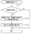
- FIG. 5 shows a flowchart of a calorific value increase control routine employed in the present embodiment. The processing of this routine is also repeatedly performed periodically by the electronic control unit 20 during operation of the internal combustion engine 10.
- the electronic control unit 20 first confirms in step S201 whether or not a heat generation amount increase request has been made. If the heat generation amount increase request is not issued (S201: NO), the electronic control unit 20 ends the processing of this routine as it is.
- step S202 the degree of heat generation in the internal combustion engine 10 is insufficient, that is, the estimated water temperature relative to the required water temperature.
- the calorific value increase control to be performed is selected according to the degree of deficiency and the operating state of the internal combustion engine 10. Then, in the following step S203, the electronic control unit 20 performs the selected heat generation amount increase control and ends the processing of this routine.
- the heat source control unit P4 that controls the operating state of the on-board internal combustion engine 10 and the heater core 17 that uses the heat generated by the internal combustion engine 10.
- the calorific value calculation unit P1 the supply heat amount estimation unit P2 that estimates the amount of heat that the internal combustion engine 10 can supply to the heater core 17 in the future, and the heat amount estimated by the supply heat amount estimation unit P2 are greater than the heat amount calculated by the necessary heat amount calculation unit P1.
- a heat generation amount increase request unit P3 that requests the heat source control unit P4 to increase the heat generation amount of the internal combustion engine 10 is provided.
- the required heat amount calculation unit P1 is configured to calculate the engine water temperature (necessary water temperature) necessary for securing the amount of heat required by the heater core 17 and the time (necessary time) when the engine water temperature is required.
- the supply heat quantity estimation unit P2 is configured to estimate the engine water temperature (estimated water temperature) at the necessary time when the current operation state of the internal combustion engine 10 is continued. Further, when the estimated water temperature is lower than the required water temperature, the heat generation amount increase request unit P3 is configured to request the heat source control unit P4 to increase the heat generation amount of the internal combustion engine 10.
- the calculation result of the amount of heat that the heater core 17 that uses the heat of the on-board internal combustion engine 10 needs in the future and the estimation result of the amount of heat that the internal combustion engine 10 can supply to the heater core 17 in the future are obtained.
- the amount of heat that can be supplied to the heater core 17 in the future by the internal combustion engine 10 is less than the amount of heat that the heater core 17 will need in the future, the amount of heat generated by the heat source control unit P4 that controls the operating state of the internal combustion engine 10 is reduced. Increase requests will be made.
- the required heat quantity calculation unit P1 calculates and supplies the engine water temperature (necessary water temperature) necessary for securing the heat quantity required by the heater core 17 and the time (necessary time) when the engine water temperature is required.
- the heat quantity estimation unit P2 estimates the engine water temperature (estimated water temperature) at the necessary time when the current operation state of the internal combustion engine 10 is continued.
- the heat source control unit P4 that controls the operation state of the internal combustion engine 10 is requested to increase the amount of heat generated by the internal combustion engine 10. That is, in the present embodiment, it is determined whether or not the amount of heat generated by the internal combustion engine 10 is excessive or insufficient after determining when and how much heat the heater core 17 requires. Therefore, according to the present embodiment, it is possible to more efficiently and accurately supply the heat required by the heater core 17 that is a heat utilization device.
- the engine water temperature (necessary water temperature) required by the heater core 17 and the engine water temperature are required.
- the time (necessary time) is calculated.
- the amount of heat that can be supplied to the heater core 17 by the internal combustion engine 10 at the calculated required time specifically, the engine water temperature at the required time is estimated. More specifically, a future transition curve of the future amount of heat (engine water temperature) that the internal combustion engine 10 can supply to the heater core 17 is obtained, and the internal combustion engine 10 supplies the heater core 17 at the necessary time from the obtained transition curve.
- the possible amount of heat (engine water temperature) is estimated. Therefore, it is possible to more accurately determine the excess or deficiency of the supplied heat amount.
- the hot air blowing temperature of the heating device is calculated based on the set temperature Tset of the heating device and the environmental conditions (the indoor temperature TR, the outdoor air temperature Tam, and the solar radiation amount Ts) outside and inside the vehicle.
- the required water temperature and the required time are calculated according to the calculated blowing temperature. Therefore, heat can be supplied from the internal combustion engine 10 to the heater core 17 so that sufficient heating performance is ensured.
- the supply heat quantity estimation unit P2 is configured to estimate the engine water temperature on the assumption that the internal combustion engine 10 is operated under an operation condition with a small heat generation quantity. Even if the internal combustion engine 10 is operated under less operating conditions, it is possible to reliably avoid a shortage of heat supplied to the heater core 17.
- the calorific value increase requesting unit P3 is configured according to the degree of shortage of the heat quantity (estimated water temperature) estimated by the supply heat quantity estimation unit P2 with respect to the heat quantity (necessary water temperature) calculated by the necessary heat quantity calculation unit P1.
- the heat source control unit P4 is configured to variably set the content of the heat generation amount increase control of the internal combustion engine 10 in response to the heat generation amount increase request. More specifically, a plurality of controls are provided as the heat generation amount increase control of the internal combustion engine 10 in response to the heat generation amount increase request of the heat generation amount increase request unit P3, and the supply heat amount with respect to the heat amount (required water temperature) calculated by the required heat amount calculation unit P1.
- the heat source control unit P4 is configured to select which heat generation amount increase control is to be performed according to the degree of shortage of the heat amount (estimated water temperature) estimated by the estimation unit P2. Then, the heat source control unit P4 selects the control that the heat generation amount of the internal combustion engine 10 that can be increased is small when the degree of heat shortage is small, but can be increased when the degree of heat shortage is large. Although the internal combustion engine 10 generates a large amount of heat, control is selected that has low heat generation efficiency. As a more specific example, the heat source control unit P4 selects the exhaust valve retarded opening control when the amount of heat shortage is small, and the ignition timing retard control when the amount of heat shortage is large. ing. Therefore, as long as the degree of heat quantity deficiency is not excessive, the heat generation amount increase control can be performed with high heat generation efficiency, and the heat supply to the heater core 17 can be performed more efficiently.
- a plurality of controls are provided as the heat generation amount increase control of the internal combustion engine 10 in response to the heat generation amount increase request of the heat generation amount increase request unit P3, and any heat generation is performed according to the operating state of the internal combustion engine 10.
- the heat source control unit P4 is configured to select whether to perform the amount increase control. That is, in the present embodiment, the heat source control unit P4 is configured to select the control with the highest heat generation efficiency as the heat generation amount increase control in the operation state of the internal combustion engine 10 at that time.
- the heat source control unit P4 selects the slow opening control of the exhaust valve as the heat generation amount increase control when the rotational speed of the internal combustion engine 10 is low, and the rotational speed of the internal combustion engine 10 is When it is high, the ignition delay angle control is selected as the heat generation amount increase control. Therefore, optimal heat generation amount increase control can be performed according to the operating state of the internal combustion engine 10 at that time, and heat supply to the heater core 17 can be performed more efficiently.
- the operation state of the internal combustion engine 10 may change and affect the running of the vehicle. Further, while the vehicle is running, the operation control of the internal combustion engine 10 in response to a request other than the heat generation amount increase request, for example, sets the output torque of the internal combustion engine 10 so as to satisfy the driver's torque request grasped from the accelerator operation amount. So-called torque demand control is performed. Therefore, if the heat generation amount increase control is performed while the vehicle is running, arbitration is required between the operation control of the internal combustion engine 10 and the heat generation amount increase control based on such other requirements, and the control becomes complicated. Therefore, in the present embodiment, the heat source control unit P4 is configured so that the heat generation amount increase control for the heat generation amount increase request of the heat generation amount increase request unit P3 is performed when the required load of the internal combustion engine 10 is zero. ing.
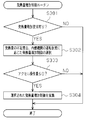
- FIG. 6 shows a flowchart of the heat generation amount increase control routine employed in this embodiment.
- the processing of this routine is repeatedly executed periodically by the electronic control unit 20 during operation of the internal combustion engine 10 instead of the heating value increase control routine of the first embodiment shown in FIG. ing.
- the electronic control unit 20 first confirms in step S301 whether or not a heat generation amount increase request has been made. If the heat generation amount increase request is not issued (S301: NO), the electronic control unit 20 ends the processing of this routine as it is.
- step S301 if the heat generation amount increase request has been issued (S301: YES), the electronic control unit 20 proceeds to step S302, and in step S302, the degree of heat generation in the internal combustion engine 10 is insufficient, that is, the estimated water temperature relative to the required water temperature.
- the calorific value increase control to be performed is selected according to the degree of deficiency and the operating state of the internal combustion engine 10.
- step S303 the electronic control unit 20 confirms whether or not the accelerator operation amount is 0 or less, that is, whether or not the required load of the internal combustion engine 10 is 0.
- the electronic control unit 20 executes the heat generation amount increase control selected in step S302 only when the accelerator operation amount is 0 or less in step S304 (S303: YES).
- the heat source control unit P4 is configured so that the heat generation amount increase control for the heat generation amount increase request of the heat generation amount increase request unit P3 is performed when the required load of the internal combustion engine 10 is zero. I am doing so. For this reason, it is possible to perform the heat generation amount increase control relatively freely without being restricted by traveling with the vehicle and other driving controls.
- the heat storage device is the following device.
- the heat storage device is configured as a heat insulating container for storing engine cooling water, stores hot engine cooling water therein during the previous vehicle travel, and cools the stored hot cooling water at the next engine start. By discharging to the water circuit, the internal combustion engine can be warmed up quickly.
- the heat generation amount increase request control and the heat generation amount increase control are basically performed in the same manner as in the above embodiment.
- calculation of the required water temperature and the required time by the required heat amount calculation unit P1 is as follows.
- the necessary heat amount calculation unit P1 sets the target value of the timing for starting storage of the high-temperature engine cooling water for the heat storage device as the necessary timing, and is necessary for early warming of the internal combustion engine 10.
- the engine water temperature is set as the required temperature.
- the necessary time at this time may be a fixed value or a variable value depending on the outside temperature.
- the required heat amount calculation part P1 calculates a required water temperature and a required time, and the process after it is performed similarly to the said embodiment.
- the same effects as (1) to (7) or similar effects can be obtained.
- the same purpose as that of the above-described embodiment is obtained only by changing the setting mode of the required water temperature and the required time by the required heat amount calculation unit P1 according to the equipment. Can be achieved.
- the heat utilization device is an oil warmer
- the required water temperature and the required time can be set based on the oil temperature and the cooling water temperature.
- the battery or motor is a heat utilization device
- the required water temperature and the required time can be set based on the outside air temperature.
- the heat generation amount increase control there are three controls of exhaust valve delay opening control, ignition timing delay control, and idle up control, and depending on the heat amount deficiency and the operating state of the internal combustion engine 10 These three controls were used properly. Control other than these may be employed as the heat generation amount increase control. Even in this case, when the degree of heat shortage is small, the control is selected to reduce the heat generation amount of the internal combustion engine 10 which is high although the heat generation efficiency is high, and when the degree of heat shortage is large, the control of the internal combustion engine 10 which can be increased is selected. By selecting a control with a large heat generation amount but low heat generation efficiency, the heat generation amount of the internal combustion engine 10 can be increased efficiently.
- the heat generation amount increase control selected according to the operation state of the internal combustion engine 10 is appropriately switched, it is possible to realize efficient heat generation amount increase control according to the operation state of the internal combustion engine 10 at that time. It becomes like this.
- various controls have conventionally been proposed as the heat generation amount increase control of the internal combustion engine 10 for the purpose of promoting warm-up. Any of the known controls can be adopted as the heat generation amount increase control.
- a plurality of heat generation amount increase controls are provided, and these controls are selectively used according to the operating state of the internal combustion engine 10 and the degree of heat shortage. Even when only a single control is provided as the calorific value increase control, it is possible to supply the heat required by the heat-using device by determining whether or not to implement it through the calorific value increase request control as in the above embodiment. It is possible to carry out more efficiently and accurately.
- the engine water temperature is used as an index value of the amount of heat that the heat utilization device will need in the future and the amount of heat that the internal combustion engine 10 that is the heat source can supply to the heat utilization device in the future.
- a parameter other than the engine water temperature may be used as the index value.
- the temperature of the heat transfer medium can be used as the index value.
- the heat generation time of the heat source can be used as an index value for the amount of heat.
- an arbitrary parameter having a correlation with the amount of heat supplied from the heat source to the heat utilization device may be used. it can. Of course, it is also possible to calculate and use the amount of heat supplied from the heat source to the heat utilization device.
- the supply heat quantity estimation unit P2 obtains a future transition curve of the amount of heat that the internal combustion engine 10 that is a heat source can supply to the heat utilization device, and can supply it at the necessary time from the obtained transition curve I was trying to estimate the amount of heat. Even if the supply heat amount estimation unit P2 obtains the supply heat amount of the heat source at the necessary time instead of a transition curve pinpoint, it is possible to determine whether there is a shortage of supply heat amount as in the above embodiment. It is.
- the supply heat quantity estimation unit P2 calculates the supply heat quantity based on the operating state of the heat source (internal combustion engine 1) (current engine speed NE, engine torque Te, etc.) and the engine water temperature ethw at that time. Although the estimation is performed, the estimation may be performed based only on the operating state of the heat source.
- the supply heat amount estimation unit P2 estimates the supply heat amount on the assumption that the current operation state of the heat source is continued. However, the past and future operation states of the heat source are taken into account. Then, the estimation may be performed. For example, when a future control schedule of the heat source is determined in advance, the amount of heat supplied can be estimated in consideration of the control schedule. As a specific example, if the catalyst warm-up control is scheduled to be implemented several seconds from now, the future heat supply will be estimated by taking into account the increase in the heat generation amount of the heat source associated with the implementation. It is possible.
- Supplied heat quantity estimation unit P2 obtains a future transition curve of the engine water temperature based on the operating state of the internal combustion engine 10. More specifically, the supply heat amount estimation unit P2 calculates a transition curve of the engine water temperature based on the current engine speed NE, engine torque Te, engine water temperature ethw, and outside air temperature Tam. In FIG. 3, the engine water temperature transition curve is a linear curve, that is, a straight line. From the transition curve thus calculated, it is possible to obtain an estimated value of the engine water temperature at the above-mentioned time calculated by the necessary heat amount calculation unit P1. Then, the supply heat amount estimation unit P2 sends the transition curve thus calculated to the heat generation amount increase request unit P3.
- the case where the internal combustion engine 10 is used as a heat source has been described.
- a device other than the internal combustion engine 10 such as a motor, an inverter, or a fuel cell as a heat source for supplying heat to a heat utilization device.
- the control device of the present invention can be similarly applied.
Landscapes
- Engineering & Computer Science (AREA)
- Chemical & Material Sciences (AREA)
- Combustion & Propulsion (AREA)
- Mechanical Engineering (AREA)
- General Engineering & Computer Science (AREA)
- Theoretical Computer Science (AREA)
- Signal Processing (AREA)
- Air-Conditioning For Vehicles (AREA)
- Combined Controls Of Internal Combustion Engines (AREA)
- Electrical Control Of Ignition Timing (AREA)
- Output Control And Ontrol Of Special Type Engine (AREA)
- Control Of Vehicle Engines Or Engines For Specific Uses (AREA)
Priority Applications (8)
| Application Number | Priority Date | Filing Date | Title |
|---|---|---|---|
| PCT/JP2009/061109 WO2010146691A1 (ja) | 2009-06-18 | 2009-06-18 | 車両の制御装置 |
| CN200980155716.6A CN102301113B (zh) | 2009-06-18 | 2009-06-18 | 车辆的控制装置 |
| US13/144,951 US8868314B2 (en) | 2009-06-18 | 2009-06-18 | Control device for vehicle |
| JP2011519369A JP5146601B2 (ja) | 2009-06-18 | 2009-06-18 | 車両の制御装置 |
| RU2011133199/06A RU2486359C2 (ru) | 2009-06-18 | 2009-06-18 | Устройство управления для транспортного средства |
| BRPI0924298-8A BRPI0924298B1 (pt) | 2009-06-18 | 2009-06-18 | Dispositivo de controle para veículo |
| EP09846184.1A EP2444638B1 (en) | 2009-06-18 | 2009-06-18 | Control device for vehicle |
| ES09846184.1T ES2625875T3 (es) | 2009-06-18 | 2009-06-18 | Dispositivo de control para vehículo |
Applications Claiming Priority (1)
| Application Number | Priority Date | Filing Date | Title |
|---|---|---|---|
| PCT/JP2009/061109 WO2010146691A1 (ja) | 2009-06-18 | 2009-06-18 | 車両の制御装置 |
Publications (1)
| Publication Number | Publication Date |
|---|---|
| WO2010146691A1 true WO2010146691A1 (ja) | 2010-12-23 |
Family
ID=43356029
Family Applications (1)
| Application Number | Title | Priority Date | Filing Date |
|---|---|---|---|
| PCT/JP2009/061109 Ceased WO2010146691A1 (ja) | 2009-06-18 | 2009-06-18 | 車両の制御装置 |
Country Status (8)
| Country | Link |
|---|---|
| US (1) | US8868314B2 (pt) |
| EP (1) | EP2444638B1 (pt) |
| JP (1) | JP5146601B2 (pt) |
| CN (1) | CN102301113B (pt) |
| BR (1) | BRPI0924298B1 (pt) |
| ES (1) | ES2625875T3 (pt) |
| RU (1) | RU2486359C2 (pt) |
| WO (1) | WO2010146691A1 (pt) |
Cited By (2)
| Publication number | Priority date | Publication date | Assignee | Title |
|---|---|---|---|---|
| JP2014152720A (ja) * | 2013-02-12 | 2014-08-25 | Hitachi Automotive Systems Ltd | 内燃機関の制御装置 |
| WO2017033661A1 (ja) * | 2015-08-25 | 2017-03-02 | 株式会社デンソー | 車両用空調システム |
Families Citing this family (23)
| Publication number | Priority date | Publication date | Assignee | Title |
|---|---|---|---|---|
| US8823203B2 (en) | 2009-11-12 | 2014-09-02 | Denso Corporation | Controller for engine |
| JP5131358B2 (ja) * | 2011-01-06 | 2013-01-30 | 株式会社デンソー | 車両の熱源制御装置 |
| JP5246374B1 (ja) * | 2011-06-15 | 2013-07-24 | トヨタ自動車株式会社 | 車両用暖房制御装置、方法及びプログラム |
| US9436497B2 (en) * | 2012-09-10 | 2016-09-06 | Apple Inc. | Linking multiple independent control systems to distribute response |
| JP2015113106A (ja) * | 2013-12-09 | 2015-06-22 | 現代自動車株式会社 | 車両用冷却システム |
| US9796244B2 (en) | 2014-01-17 | 2017-10-24 | Honda Motor Co., Ltd. | Thermal management system for a vehicle and method |
| DE102014211529B4 (de) * | 2014-06-17 | 2016-02-18 | Ford Global Technologies, Llc | Verfahren und Vorrichtung zum Betrieb eines Wärmespeichers in einem Kraftfahrzeug |
| US10005339B2 (en) * | 2015-05-26 | 2018-06-26 | GM Global Technology Operations LLC | Vehicle thermal management system and control method for the same |
| US10059167B2 (en) * | 2015-05-28 | 2018-08-28 | GM Global Technology Operations LLC | Location based remote start |
| KR101745159B1 (ko) * | 2015-10-28 | 2017-06-08 | 현대자동차주식회사 | 쓰로틀바디의 냉각수 공급 장치 및 방법 |
| US10246073B2 (en) | 2016-05-16 | 2019-04-02 | Ford Global Technologies, Llc | Control system for a hybrid-electric vehicle |
| US10196994B2 (en) | 2016-05-16 | 2019-02-05 | Ford Global Technologies, Llc | Powertrain control system |
| US10759255B2 (en) * | 2016-07-20 | 2020-09-01 | Ford Global Technologies, Llc | Autonomous-vehicle climate-control system |
| US10263807B2 (en) * | 2016-12-19 | 2019-04-16 | Ciena Corporation | Hierarchical statistics acceleration |
| JP6583339B2 (ja) * | 2017-04-11 | 2019-10-02 | トヨタ自動車株式会社 | 内燃機関の制御装置 |
| US10603982B2 (en) * | 2017-10-19 | 2020-03-31 | Ford Global Technologies, Llc | Vehicular climate control system |
| US11094950B2 (en) | 2017-11-28 | 2021-08-17 | Toyota Motor Engineering & Manufacturing North America, Inc. | Equation based state estimator for cooling system controller |
| US10720655B2 (en) | 2017-11-28 | 2020-07-21 | Toyota Motor Engineering & Manufacturing North America, Inc. | Partial derivative based feedback controls for pid |
| US10777831B2 (en) | 2017-11-28 | 2020-09-15 | Toyota Motor Engineering & Manufacturing North America, Inc. | Equation based cooling system control strategy/method |
| US10714773B2 (en) | 2017-11-28 | 2020-07-14 | Toyota Motor Engineering & Manufacturing North America, Inc. | Cooling system dT/dt based control |
| JP7114920B2 (ja) * | 2018-02-07 | 2022-08-09 | トヨタ自動車株式会社 | 熱エネルギー制御システム、熱量分配器、車両の熱エネルギー制御方法 |
| EP4153817B1 (en) * | 2020-05-18 | 2025-07-23 | Volvo Construction Equipment AB | Vehicle with control unit |
| CN115843331A (zh) * | 2020-08-18 | 2023-03-24 | 三菱电机株式会社 | 红外线传感器装置 |
Citations (5)
| Publication number | Priority date | Publication date | Assignee | Title |
|---|---|---|---|---|
| JPS61155637A (ja) * | 1984-12-28 | 1986-07-15 | Suzuki Motor Co Ltd | 燃料噴射制御装置 |
| JPH03160136A (ja) * | 1989-11-15 | 1991-07-10 | Nissan Motor Co Ltd | 空調装置を備えた車両 |
| JP2005016465A (ja) * | 2003-06-27 | 2005-01-20 | Suzuki Motor Corp | エンジンの制御装置 |
| JP2005207321A (ja) * | 2004-01-22 | 2005-08-04 | Toyota Motor Corp | 内燃機関の制御装置 |
| JP2006161625A (ja) * | 2004-12-06 | 2006-06-22 | Denso Corp | 内燃機関の排気温度推定装置 |
Family Cites Families (11)
| Publication number | Priority date | Publication date | Assignee | Title |
|---|---|---|---|---|
| DE19543783A1 (de) * | 1995-11-24 | 1997-05-28 | Bayerische Motoren Werke Ag | Betriebsverfahren für eine Fahrzeug-Brennkraftmaschine mit Leerlauf-Drehzahl-Regelung |
| JP3577961B2 (ja) * | 1998-02-27 | 2004-10-20 | トヨタ自動車株式会社 | 燃焼式ヒータを有する内燃機関 |
| JP3414318B2 (ja) | 1999-04-28 | 2003-06-09 | トヨタ自動車株式会社 | 内燃機関の燃焼制御装置 |
| RU2168642C1 (ru) * | 1999-11-22 | 2001-06-10 | Закрытое акционерное общество "Волжский дизель им. Маминых" | Система жидкостного охлаждения тепловой машины |
| KR100348588B1 (ko) * | 2000-07-07 | 2002-08-14 | 국방과학연구소 | 차량용 냉각장치 |
| JP4682489B2 (ja) * | 2001-09-17 | 2011-05-11 | 株式会社デンソー | 車両用空調装置 |
| DE10306457B4 (de) * | 2003-02-17 | 2014-03-20 | Robert Bosch Gmbh | Verfahren und Vorrichtung zur Heizleistungserhöhung bei Kraftfahrzeugen mit Verbrennungsmotoren |
| JP2006170060A (ja) * | 2004-12-15 | 2006-06-29 | Yanmar Co Ltd | 内燃機関の過給装置 |
| US7236875B2 (en) * | 2005-03-28 | 2007-06-26 | Ford Global Technologies, Llc | System and method for controlling an engine in a vehicle |
| JP4894733B2 (ja) * | 2007-11-16 | 2012-03-14 | マツダ株式会社 | 水素エンジンを用いたコージェネレーションシステム |
| JP5131358B2 (ja) * | 2011-01-06 | 2013-01-30 | 株式会社デンソー | 車両の熱源制御装置 |
-
2009
- 2009-06-18 EP EP09846184.1A patent/EP2444638B1/en not_active Not-in-force
- 2009-06-18 WO PCT/JP2009/061109 patent/WO2010146691A1/ja not_active Ceased
- 2009-06-18 US US13/144,951 patent/US8868314B2/en active Active
- 2009-06-18 CN CN200980155716.6A patent/CN102301113B/zh not_active Expired - Fee Related
- 2009-06-18 JP JP2011519369A patent/JP5146601B2/ja not_active Expired - Fee Related
- 2009-06-18 BR BRPI0924298-8A patent/BRPI0924298B1/pt not_active IP Right Cessation
- 2009-06-18 ES ES09846184.1T patent/ES2625875T3/es active Active
- 2009-06-18 RU RU2011133199/06A patent/RU2486359C2/ru active
Patent Citations (5)
| Publication number | Priority date | Publication date | Assignee | Title |
|---|---|---|---|---|
| JPS61155637A (ja) * | 1984-12-28 | 1986-07-15 | Suzuki Motor Co Ltd | 燃料噴射制御装置 |
| JPH03160136A (ja) * | 1989-11-15 | 1991-07-10 | Nissan Motor Co Ltd | 空調装置を備えた車両 |
| JP2005016465A (ja) * | 2003-06-27 | 2005-01-20 | Suzuki Motor Corp | エンジンの制御装置 |
| JP2005207321A (ja) * | 2004-01-22 | 2005-08-04 | Toyota Motor Corp | 内燃機関の制御装置 |
| JP2006161625A (ja) * | 2004-12-06 | 2006-06-22 | Denso Corp | 内燃機関の排気温度推定装置 |
Non-Patent Citations (1)
| Title |
|---|
| See also references of EP2444638A4 * |
Cited By (2)
| Publication number | Priority date | Publication date | Assignee | Title |
|---|---|---|---|---|
| JP2014152720A (ja) * | 2013-02-12 | 2014-08-25 | Hitachi Automotive Systems Ltd | 内燃機関の制御装置 |
| WO2017033661A1 (ja) * | 2015-08-25 | 2017-03-02 | 株式会社デンソー | 車両用空調システム |
Also Published As
| Publication number | Publication date |
|---|---|
| EP2444638A1 (en) | 2012-04-25 |
| BRPI0924298A2 (pt) | 2016-01-26 |
| CN102301113A (zh) | 2011-12-28 |
| BRPI0924298B1 (pt) | 2019-05-21 |
| RU2486359C2 (ru) | 2013-06-27 |
| EP2444638B1 (en) | 2017-04-12 |
| US20120074238A1 (en) | 2012-03-29 |
| ES2625875T3 (es) | 2017-07-20 |
| JPWO2010146691A1 (ja) | 2012-11-29 |
| CN102301113B (zh) | 2014-08-27 |
| US8868314B2 (en) | 2014-10-21 |
| EP2444638A4 (en) | 2014-06-18 |
| JP5146601B2 (ja) | 2013-02-20 |
Similar Documents
| Publication | Publication Date | Title |
|---|---|---|
| JP5146601B2 (ja) | 車両の制御装置 | |
| US8683969B2 (en) | Vehicular control device | |
| US7762232B2 (en) | Engine and exhaust heating for hybrid vehicle | |
| US8353265B2 (en) | Efficient vehicle component heating | |
| JP5120319B2 (ja) | エンジンの廃熱制御装置 | |
| US9404402B2 (en) | Efficient vehicle component heating | |
| US7080609B2 (en) | Engine system with a thermal storage device, and engine temperature raising method | |
| JP2012171520A (ja) | 電動車両の制御装置 | |
| US10913327B2 (en) | Air conditioner for vehicle | |
| CN116587807B (zh) | 车辆暖风控制方法、控制装置、存储介质及车辆控制器 | |
| JP5452265B2 (ja) | エンジンの廃熱制御装置 | |
| JP2006161745A (ja) | 車両の制御装置 | |
| JP2014105686A (ja) | エンジンの冷却水温推定装置及びエンジン制御装置 | |
| JP6089636B2 (ja) | エンジンの冷却水温推定装置及びエンジン制御装置 | |
| JP2013010507A (ja) | 車両の制御装置 | |
| JP4941538B2 (ja) | エンジンの廃熱制御装置 | |
| JP2006170064A (ja) | 車両の制御装置 | |
| JP5267706B2 (ja) | エンジンの廃熱制御装置 | |
| JP2025056627A (ja) | エンジンシステムの制御装置 | |
| JP2006207457A (ja) | 回転電機の制御装置 | |
| JP2006170065A (ja) | 車両の制御装置 | |
| JP2011226443A (ja) | エンジンの廃熱制御装置 | |
| JP2006226265A (ja) | 異常診断装置 |
Legal Events
| Date | Code | Title | Description |
|---|---|---|---|
| WWE | Wipo information: entry into national phase |
Ref document number: 200980155716.6 Country of ref document: CN |
|
| 121 | Ep: the epo has been informed by wipo that ep was designated in this application |
Ref document number: 09846184 Country of ref document: EP Kind code of ref document: A1 |
|
| ENP | Entry into the national phase |
Ref document number: 2011519369 Country of ref document: JP Kind code of ref document: A |
|
| WWE | Wipo information: entry into national phase |
Ref document number: 13144951 Country of ref document: US |
|
| REEP | Request for entry into the european phase |
Ref document number: 2009846184 Country of ref document: EP |
|
| WWE | Wipo information: entry into national phase |
Ref document number: 2009846184 Country of ref document: EP |
|
| WWE | Wipo information: entry into national phase |
Ref document number: 5713/DELNP/2011 Country of ref document: IN |
|
| NENP | Non-entry into the national phase |
Ref country code: DE |
|
| WWE | Wipo information: entry into national phase |
Ref document number: 2011133199 Country of ref document: RU |
|
| REG | Reference to national code |
Ref country code: BR Ref legal event code: B01A Ref document number: PI0924298 Country of ref document: BR |
|
| ENP | Entry into the national phase |
Ref document number: PI0924298 Country of ref document: BR Kind code of ref document: A2 Effective date: 20110809 |