WO2010146887A1 - Véhicule de déplacement - Google Patents
Véhicule de déplacement Download PDFInfo
- Publication number
- WO2010146887A1 WO2010146887A1 PCT/JP2010/051758 JP2010051758W WO2010146887A1 WO 2010146887 A1 WO2010146887 A1 WO 2010146887A1 JP 2010051758 W JP2010051758 W JP 2010051758W WO 2010146887 A1 WO2010146887 A1 WO 2010146887A1
- Authority
- WO
- WIPO (PCT)
- Prior art keywords
- traveling
- machine body
- actuator
- traveling machine
- arm
- Prior art date
- Legal status (The legal status is an assumption and is not a legal conclusion. Google has not performed a legal analysis and makes no representation as to the accuracy of the status listed.)
- Ceased
Links
Images










Classifications
-
- A—HUMAN NECESSITIES
- A01—AGRICULTURE; FORESTRY; ANIMAL HUSBANDRY; HUNTING; TRAPPING; FISHING
- A01D—HARVESTING; MOWING
- A01D75/00—Accessories for harvesters or mowers
- A01D75/28—Control mechanisms for harvesters or mowers when moving on slopes; Devices preventing lateral pull
-
- B—PERFORMING OPERATIONS; TRANSPORTING
- B62—LAND VEHICLES FOR TRAVELLING OTHERWISE THAN ON RAILS
- B62D—MOTOR VEHICLES; TRAILERS
- B62D55/00—Endless track vehicles
- B62D55/08—Endless track units; Parts thereof
- B62D55/104—Suspension devices for wheels, rollers, bogies or frames
- B62D55/116—Attitude or position control of chassis by action on suspension, e.g. to compensate for a slope
-
- A—HUMAN NECESSITIES
- A01—AGRICULTURE; FORESTRY; ANIMAL HUSBANDRY; HUNTING; TRAPPING; FISHING
- A01D—HARVESTING; MOWING
- A01D67/00—Undercarriages or frames specially adapted for harvesters or mowers; Mechanisms for adjusting the frame; Platforms
-
- B—PERFORMING OPERATIONS; TRANSPORTING
- B62—LAND VEHICLES FOR TRAVELLING OTHERWISE THAN ON RAILS
- B62D—MOTOR VEHICLES; TRAILERS
- B62D55/00—Endless track vehicles
- B62D55/08—Endless track units; Parts thereof
- B62D55/12—Arrangement, location, or adaptation of driving sprockets
- B62D55/125—Final drives
Definitions
- the present invention relates to a combine harvester that harvests cereal grains planted in a field and collects grains, or a feed combine that harvests cereal grains for feed and collects it as feed, or a traveling vehicle such as a transport vehicle that travels on rough terrain. More specifically, the present invention relates to a traveling vehicle including a traveling unit such as a pair of left and right traveling crawlers.
- a traveling vehicle such as a combiner includes a traveling machine body equipped with an engine, and a pair of left and right traveling crawlers are mounted on the traveling machine body, and the pair of left and right traveling crawlers are driven and controlled to move in a farm field or the like.
- the combine cuts the stock of uncut cereal planted in the field with a cutting blade device, conveys the cereal to a threshing device with a cereal conveying device as a cereal conveying means, and The cereals are threshed to collect the grains (see, for example, Patent Document 1).
- a rolling actuator that corrects the tilting posture of the traveling aircraft in the left-right direction and a pitching actuator that corrects the tilting posture of the traveling aircraft in the front-rear direction
- a track frame on which the traveling crawler is mounted and a parallel link-shaped front side
- the track frame is connected to the traveling vehicle body via the arm and the rear arm
- the rolling actuator is connected to the front arm and the rear arm via the connecting rod via the front and rear tilt arms
- the traveling aircraft is operated by the operation of the rolling actuator.
- the tilt posture in the left-right direction is changed (see, for example, Patent Document 1 and Patent Document 2).
- a pitching actuator is provided in the middle of the connection of the front and rear left and right tilt arms, and the pitching actuator is configured to change the tilting posture in the front-rear direction of the traveling machine body.
- the connecting length of the front and rear left and right tilt arms is considerably longer, and there is a problem of durability such that a twisting force other than the expansion / contraction direction tends to act on the pitching actuator.
- the pitching actuator since the pitching actuator is disposed on the lower surface side of the traveling machine body below the rolling actuator, the pitching actuator or hydraulic piping is supported between the left and right traveling crawlers.
- the pitching actuator is configured to move the rear arm and the rear left and right tilt arms up and down to change the tilting posture of the traveling aircraft in the front-rear direction, the pitching actuator is supported on the upper surface side of the traveling aircraft.
- the upper surface side structure of the traveling machine body or the support position of the pitching actuator being mutually restricted.
- Patent Document 1 includes a front-rear connecting rolling frame that connects front and rear left and right tilting arms, and a pitching actuator is provided in the middle of the front-rear connecting rolling frame extending in the front-rear direction. Because the connecting length of the front and rear left and right tilt arms is considerably longer than the operating stroke of the pitching actuator, the front and rear There is a structural problem such that a twisting force (compression force) other than the expansion / contraction direction acts on the connecting rolling frame and the front / rear connecting rolling frame and its connecting portion are easily damaged.
- a twisting force compression force
- Patent Document 2 when the rear part of the track frame is moved up and down by the pitching actuator to change the tilting posture of the traveling body in the front-rear direction, the rolling actuator is also operated. There is a problem in handling such as troublesome operation to change the tilt posture in the front-rear direction of the aircraft.
- An object of the present invention is to provide a traveling vehicle in which the durability of the pitching actuator can be improved, the pitching actuator can be arranged in a compact manner, and the traveling machine body can be easily configured. Further, it is an object of the present invention to provide a traveling vehicle that can improve the durability of the support structure of the traveling machine body and the track frame, and that can easily change the inclination posture of the traveling machine body in the front-rear direction by controlling the pitching actuator. .
- a traveling vehicle includes a traveling machine body having left and right traveling units, a rolling actuator that corrects a tilting posture of the traveling machine body in a lateral direction, and a longitudinal direction of the traveling machine body.
- the rolling actuator and the pitching actuator are arranged in a line in a plan view.
- the rolling actuator and the pitching actuator are arranged in a line in a side view.
- the traveling vehicle body is mounted on the left and right track frames so that the traveling vehicle body can be moved up and down via a left and right link mechanism,
- the structure in which the tilting posture in the front-rear direction of the traveling aircraft body can be corrected, and the link mechanism has a parallel link-like front arm and rear arm, and a pitching link is provided on the track frame. Either the front arm or the rear arm is connected.
- the left / right tilt arm connected to the rolling actuator and the front / back tilt arm connected to the pitching actuator are arranged on the same fulcrum shaft,
- the structure is provided with a parallel link-like front arm and rear arm that are actuated by the rolling actuator, and the front and rear tilt arms are connected to either the front arm or the rear arm.
- either the rear arm or the front arm is connected to the rolling actuator, and both the front arm and the rear arm are connected to the pitching link.
- the pitching actuator is connected to one side.
- a transmission is arranged at a front portion of the traveling aircraft body, the pitching actuator is connected to the rear arm, and the track frame Further, the rear arm is connected via the pitching link.
- the left / right tilt arm connected to the rolling actuator and the front / back tilt arm connected to the pitching actuator are arranged on the same fulcrum shaft,
- the pitching actuator is provided on a left and right tilt arm connected to the rolling actuator, and the rolling actuator and the pitching actuator are arranged in a line in the front-rear direction.
- the rolling actuator when the traveling machine body is supported at the lowest lowered position, the rolling actuator is operated to raise the vehicle height, so that the traveling machine body is predetermined.
- the pitching actuator is configured to be tilted forward or backward while being supported at a height position.
- a left / right inclination sensor that detects a lateral inclination of the traveling aircraft body, and a left ground height and a right ground height of the traveling aircraft body are detected.
- Left and right vehicle height sensors, and a front / rear inclination sensor for detecting a front / rear direction inclination of the traveling vehicle body, and the rolling actuator is operated to raise or lower the vehicle height to move the vehicle body horizontally
- the pitching actuator is configured to be capable of tilting forward and backward based on the detection results of the left vehicle height sensor and the right vehicle height sensor and the detection result of the longitudinal tilt sensor. It is.
- the pitching actuator when the traveling machine body is supported at the highest position, the pitching actuator is configured to be able to tilt forward, while the traveling machine body Is configured such that the pitching actuator can be tilted backward while the rolling actuator is lowered at a vehicle height and the traveling vehicle body is supported at a predetermined height position. is there.
- a traveling machine body having left and right traveling units, a rolling actuator that corrects a tilting attitude of the traveling machine body in the left-right direction, and a pitching actuator that corrects a tilting attitude of the traveling machine body in the front-rear direction. Since the rolling actuator and the pitching actuator are arranged in a line in a plan view, the installation length (connection support length) of the pitching actuator can be shortened compared to the conventional vehicle. The twisting force other than the expansion / contraction direction acting on the pitching actuator can be reduced, and the durability can be improved.
- a space on the lower surface side of the traveling machine body between the left and right traveling parts can be formed widely, mud can be reduced from accumulating on the lower surface side of the traveling machine body, and wet field workability can be improved.
- the installation length (connection support length) of the pitching actuator is larger than the conventional one. It can be shortened, the twisting force other than the stretching direction acting on the pitching actuator can be reduced, and the durability can be improved. Further, a space on the lower surface side of the traveling machine body between the left and right traveling parts can be formed widely, mud can be reduced from accumulating on the lower surface side of the traveling machine body, and wet field workability can be improved. Moreover, it is possible to prevent the upper surface side structure of the traveling aircraft body or the support position of the pitching actuator from being restricted to each other, and the traveling aircraft body and the like can be configured easily.
- the traveling machine body is mounted on the left and right track frames so as to be movable up and down via the left and right link mechanisms, and the lateral inclination posture of the traveling machine body and the forward and backward inclination of the traveling machine body are mounted.
- the structure is configured such that the posture can be corrected, and the link mechanism has a parallel link-like front arm and rear arm, and the front or rear arm of the track frame is connected to the track frame via a pitching link. Since either one is connected, the front arm or the rear side can be moved while the traveling machine body can be tilted left and right by the operation of the front and rear arms of the parallel link shape (the rolling actuator control).
- the front or rear side of the track frame is moved up and down via either one of the arms and the pitching link (the pitching Actuator control), the vehicle body can be tilted back and forth.
- the traveling vehicle body can be tilted back and forth in a state where the vehicle height of the traveling vehicle body in the left-right tilted posture is maintained (the rolling actuator control is stopped).
- the connecting structure of the traveling machine body and the track frame can be easily configured, or the control of the pitching actuator can be easily executed.
- a pitching structure for changing the tilt posture in the front-rear direction of the traveling aircraft body can be assembled at low cost, or a pitching control function for changing the tilt posture in the front-rear direction of the travel aircraft body can be improved.
- the left and right tilt arms connected to the rolling actuator and the front and rear tilt arms connected to the pitching actuator are arranged on the same fulcrum shaft, and are operated by the rolling actuator. Since the front and rear tilt arms are connected to either the front arm or the rear arm, the front arm and the rear arm are provided. Regardless, you can use the same type of aircraft.
- the traveling machine body and the like can be configured at low cost.
- the traveling vehicle body can be tilted back and forth while maintaining the vehicle height of the traveling vehicle body in a left-right inclined posture. It is possible to maintain the control performance of the rolling actuator that corrects the tilting posture of the traveling aircraft in the left-right direction, and to improve the control performance of the pitching actuator that corrects the tilting posture of the traveling aircraft in the front-rear direction.
- both the front arm and the rear arm are connected to the rolling actuator, and the pitching actuator is connected to either the rear arm or the front arm connected to the pitching link. Therefore, the pitching actuator can be assembled in a compact manner close to the rolling actuator. Further, it is possible to improve the pitching function for changing the front-rear direction tilt posture of the travel aircraft body, while preventing the rolling function for changing the left-right direction tilt posture of the travel aircraft body from being complicated.
- a transmission is arranged in a front portion of the traveling aircraft body, the pitching actuator is connected to the rear arm, and the rear is connected to the track frame via the pitching link. Since the side arm is connected, the traveling aircraft body is changed when the front and rear portions of the track frame are installed close to the support portion of the transmission case to change the inclination posture of the traveling aircraft body in the front-rear direction. It can prevent that the lower surface side of this and the upper surface side of the said travel part interfere.
- the pitching actuator can be assembled in a compact manner in a line at substantially the same height from the middle to the rear of the track frame, in close proximity to the rolling actuator. For example, it is possible to easily ensure a tilt change range in the front-rear direction of the traveling machine body or simplify a connection structure between the traveling machine body and the track frame.
- the left / right tilt arm connected to the rolling actuator and the front / rear tilt arm connected to the pitching actuator are arranged on the same fulcrum shaft, and the right / left tilt arm connected to the rolling actuator.
- the pitching actuator is provided, and the rolling actuator and the pitching actuator are arranged in a row in the front-rear direction. Therefore, the specification with the pitching actuator and the specification without the pitching actuator have the same specifications.
- the traveling aircraft can be easily shared.
- a space between the left and right traveling parts is formed widely on the lower surface side of the traveling machine body so that the traveling part is easy to sink, and workability such as wet fields, etc., or mud such as paddy fields is likely to rise greatly by turning. It can improve the running performance of farmland headlands.
- the rolling actuator when the traveling machine body is supported at the lowest position, the rolling actuator is operated to raise the vehicle height, and the traveling machine body is supported at a predetermined height position. Since the pitching actuator is configured to be tilted forward or backward, the connecting structure between the traveling machine body and the traveling portion (such as a track frame) can be easily configured as compared with the conventional structure. Further, it is possible to easily prevent the traveling unit (such as a traveling crawler attached to a track frame) and the traveling machine body from interfering with each other. For example, the traveling machine body can be tilted forward without being restricted by a lowermost stopper or the like that sets the lower limit of the vehicle height adjustment range of the rolling actuator. Further, when the pitching actuator is tilted backward, it is possible to prevent the traveling unit (traveling crawler, etc.) from interfering with the traveling machine body, and the traveling machine body can be smoothly operated in a backwardly inclined posture.
- the traveling unit such as a traveling crawler attached to a track frame
- the left-right inclination sensor which detects the inclination of the left-right direction of the said traveling body, the left vehicle height sensor and the right vehicle height which detect the left ground height and the right ground height of the said traveling body
- a structure including a sensor and a front / rear inclination sensor for detecting a front / rear direction inclination of the traveling machine body, and the rolling actuator is operated to raise or lower the vehicle height to change the lateral inclination of the traveling machine body
- the pitching actuator is configured to be capable of tilting forward and backward based on the detection results of the left and right vehicle height sensors and the detection result of the front and rear tilt sensor.
- the pitching actuator when the traveling machine body is supported at the highest position, the pitching actuator is configured to be able to tilt forward, while the traveling machine body is supported at the highest position.
- the rolling actuator is operated to lower the vehicle height, and the pitching actuator is configured to be able to tilt backward while the traveling aircraft is supported at a predetermined height position.
- the traveling machine body While maintaining the position, the traveling machine body can be easily changed to a predetermined forward leaning posture. That is, the traveling machine body can be smoothly operated in the forward tilted posture without lowering the vehicle height.
- the pitching actuator is tilted backward, it is possible to prevent the traveling unit (running crawler, etc.) from interfering with the traveling machine body, and the traveling machine body can be smoothly operated in a backwardly inclined posture.
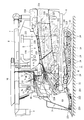
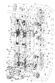
- FIG. 2 is a drive system diagram of the combine of FIG. 1. It is drive system diagrams, such as a mission case. It is drive system diagrams, such as a counter case.
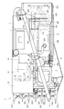
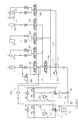
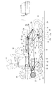
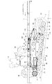
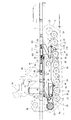
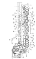
- FIG. 2 is a hydraulic circuit diagram of the combine of FIG. 1. It is a side view of a traveling machine body and a traveling crawler part. It is the same top view. It is side surface explanatory drawing which moved the traveling body up.
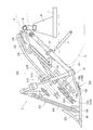
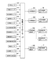
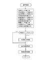
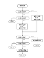
- FIG. 5 is an explanatory diagram of a front descending side in which a traveling machine body is moved upward and tilted forward. It is front-downside side explanatory drawing which made the traveling body tilt forward. It is a back descending side surface explanatory view which moved the traveling body up and inclined backward. It is back down side surface explanatory drawing which made the traveling body tilt backward. It is a rear view perspective view of a traveling crawler part. It is a diagram which shows the relationship between the ground height of a traveling body and the front-back inclination angle of a traveling body. It is a functional block diagram of a control circuit of the attitude control means. It is a flowchart of attitude control. It is a flowchart of the cereal cutting height control.
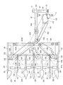
- FIG. 1 It is a flowchart of the inclination control of the left-right direction and the front-back direction. It is side surface explanatory drawing which shows a traveling body, a track frame, and a mission case. It is side explanatory drawing which shows a vehicle height adjustment hydraulic cylinder, the hydraulic cylinder for front-back inclination, a rolling link mechanism, and a pitching link mechanism. It is a top view perspective view of FIG.
- FIG. 1 is a left side view of the combine
- FIG. 2 is a plan view of the combine.
- the left side in the forward direction of the traveling machine body 1 is simply referred to as the left side
- the right side in the forward direction is also simply referred to as the right side.
- a traveling machine body 1 supported by a pair of left and right traveling crawlers 2 as a traveling unit is provided.
- a 6-row mowing device 3 that takes in while harvesting cereals is mounted by a single-acting lifting hydraulic cylinder 4 so as to be movable up and down around the mowing pivot fulcrum shaft 4 a.
- the A threshing device 5 having a feed chain 6 and a grain tank 7 for storing grains taken out from the threshing device 5 are mounted side by side on the traveling machine body 1.
- the threshing device 5 is disposed on the left side in the forward direction of the traveling machine body 1, and the grain tank 7 is disposed on the right side in the forward direction of the traveling machine body 1.
- a swivelable discharge auger 8 is provided at the rear part of the traveling machine body 1, and the grains inside the grain tank 7 are discharged from the throat throw 9 of the discharge auger 8 to a truck bed or a container. ing.
- An operation cabin 10 is provided on the right side of the reaping device 3 and on the front side of the grain tank 7.
- a steering handle 11, a driving seat 12, a main transmission lever 43, an auxiliary transmission switch 44, and a work clutch lever 45 for turning on and off the threshing clutch and the mowing clutch are arranged.
- the operation cabin 10 is provided with a step (not shown) on which an operator gets on, a handle column 46 provided with the steering handle 11, and a lever column 47 provided with the levers 43 and 45, the switch 44 and the like. ing.
- An engine 14 as a power source is disposed in the traveling machine body 1 below the driver seat 12.
- left and right track frames 21 are arranged on the lower surface side of the traveling machine body 1.
- the track frame 21 includes a drive sprocket 22 that transmits the power of the engine 14 to the traveling crawler 2, a tension roller 23 that maintains the tension of the traveling crawler 2, and a plurality of track rollers that hold the ground side of the traveling crawler 2 in a grounded state. 24 and an intermediate roller 25 that holds the non-grounded side of the traveling crawler 2 are provided.
- the driving sprocket 22 supports the front side of the traveling crawler 2
- the tension roller 23 supports the rear side of the traveling crawler 2
- the track roller 24 supports the grounding side of the traveling crawler 2
- the intermediate roller 25 supports the non-traveling crawler 2. Support the ground side.
- a clipper that cuts the stock of uncut grain cereals (grain culms) planted in the field.
- a type of cutting blade device 222 is provided in front of the mowing frame 221, a stalk raising apparatus 223 for six stalks that raises an uncut cereal cultivated in the field is disposed.
- a culm conveying device 224 that conveys the chopped culm harvested by the cutting blade device 222 is arranged.
- a weeding body 225 corresponding to six strips for weeding the uncut grain rice planted in the field is provided. While the traveling crawler 2 is driven by the engine 14 and moved in the field, the uncut cereal grains planted in the field are continuously cut by the cutting device 3.
- the cutting frame 221 includes a cutting input case 16 that is rotatably supported on the bearing stand 15 on the front end side of the traveling machine body 1, and a vertical transmission that extends forward from the cutting input case 16.
- a case 18, a horizontal transmission case 19 extending in the left-right direction on the front end side of the vertical transmission case 18, and a weeding frame 20 for six strips connected to the horizontal transmission case 19 are formed.
- On the front end side of the weeding frame 20, six weeding bodies 225 are arranged.
- a cutting input shaft 17 to which power from the engine 14 is transmitted is incorporated in a cutting input case 16 that is horizontally mounted in the horizontal direction of the machine body.
- the cereal haul raising device 223 has an erecting case 129 for 6 lanes having a plurality of erecting tines 128 for erecting the uncut cereal hay that has been weeded by the weed board 225.
- the grain feeder 224 includes left and right right star wheels 130R and left and right right scooping belts 131R that squeeze the stock side of the right two grain grains introduced from the two right side pulling cases 129, and the left side.
- Left and right left star foils 130L and left and right left rake belts 131L that scrape the stock side of the left two cereal grains introduced from the two pulling cases 129, and the center introduced from the center two pulling cases 129 It has left and right central star foils 130C and left and right central scoring belts 131C for scooping the stock side of the cereals for two strips.
- the cutting blade device 222 is scraped by the right star wheel 130R and the right and left right scooping belts 131R, the left star wheel 130L and the left and right left scooping belts 131L, the central star wheel 130C, and the left and right central scoring belts 131C. It has clipper-shaped left and right cutting blades 132 for cutting the stock of the cereal grains.
- the cereal carrying device 224 is configured to convey the right side of the right side of the stock of the right side of the chopped cereal that has been raked by the right side of the star foil 130R and the rake belt 131R.
- left stock transport that joins the stock side of the left two cropped grains that have been scraped by the left two star foils 130L and the scraping belt 131L to the transport end of the right stock transport chain 133R
- the stock side of the harvested cereal grains for 6 ridges is joined to the transport end of the right stock transport chain 133R.
- the cereal feeder 224 is fed from a vertical conveyor chain 134 as a cereal conveyor means that inherits the stock side of the harvested cereals for 6 stakes from the right stock former transport chain 133R, and fed from the end of conveyance of the vertical conveyor chain 134.
- Auxiliary stock source transport chains 135 and 136 as auxiliary transport means for transporting the stock source side of the harvested cereals for six strips are provided at the transport start end of the chain 6. From the vertical conveyance chain 134, the stock side of the harvested cereals for 6 ridges is conveyed to the conveyance start end portion of the feed chain 6 through the auxiliary stock source conveyance chains 135 and 136.
- the grain culm transporting device 224 is transported by the right stalk transporting tine 137R that transports the tip of the harvested cereals for the two right-hand ridges transported by the right stock transporting chain 133R and the left stock transporting chain 133L.
- Left tip transport tine 137L that transports the tip side of the left-hand two-line harvested grain culm
- central tip transport tine that transports the tip side of the center two-part harvested grain culm that is transported by the central stock transport chain 133C 137C
- a rear tip transport tine 138 that transports the tip of the harvested cereal rice straw for six strips transported by the vertical transport chain 134.
- the tip side of the harvested cereal grains for the six strips harvested by the reaping device 3 is conveyed into the handling cylinder 226 installation chamber of the threshing device 5.
- the pulling lateral transmission shaft 143 is connected to the cutting input shaft 17 through the longitudinal transmission shaft 140, the lateral transmission shaft 141, and the left conveyance drive shaft 142.
- the pulling lateral transmission shaft 143 is connected to the pulling tine drive shaft 144 of each pulling case 29 for six lines.
- a pulling case 129 is erected on the rear side of the weed body 225 and above the weeding frame 20, and the pulling tine drive shaft 144 protrudes from the rear surface on the upper end side of the pulling case 129.
- the pulling tine chain 128a provided with a plurality of pulling tines 128 is driven via the pulling tine drive shaft 144 and the pulling lateral transmission shaft 143.
- the left and right cutting blades 132 are connected to the lateral transmission shaft 141 via the left and right crankshafts 145.
- the left and right cutting blades 132 are configured to be driven synchronously via the lateral transmission shaft 141.
- the cutting blade device 222 is divided at the central portion of the cutting width for six lines to form the left and right cutting blades 132, and the left and right cutting blades 132 are reciprocated in opposite directions, and the left and right generated by the reciprocating movement.
- the cutting blade 132 is configured to be able to cancel the vibration (inertial force).
- one end side of the longitudinal transmission shaft 140 in the longitudinal transmission case 18 is connected to the cutting input shaft 17.
- the lateral transmission shaft 141 in the lateral transmission case 19 is connected to the other end side of the longitudinal transmission shaft 140.
- the rotational force of the cutting input shaft 17 is transmitted from the vertical transmission shaft 140 and the horizontal transmission shaft 141 to each drive unit of the cereal conveying device 224.
- the right transmission drive shaft 146 is connected to the vertical transmission shaft 140.
- the right stock former transport chain 133R and the right tip transport tine 137R, the right star wheel 130R and the right take-up belt 131R are driven.
- the auxiliary stock former transport chains 135 and 136 and the rear tip transport tine 138 are driven via the vertical transmission shaft 140 and the rear transport drive shaft 147.
- the left transport drive shaft 142 is connected to the left end side of the horizontal transmission shaft 141.
- the left stock former transport chain 133L and the left tip transport tine 137L, the left star wheel 130L, and the left take-up belt 131L are driven via the left transport drive shaft 142.
- a central transport drive shaft 148 is connected to the lateral transmission shaft 141, and the central stock transport chain 133C and the central tip transport tine 137C, the central star wheel 130C, and the central scraping belt 131C are connected via the central transport drive shaft 148. Is configured to be driven.
- the threshing device 5 includes a handling cylinder 226 for threshing threshing, a rocking sorter 227 that sorts the cereals falling below the handling cylinder 226, and a tang fan 228.
- a processing cylinder 229 that reprocesses the threshing waste taken out from the rear part of the cylinder 226 and a dust exhaust fan 230 that discharges dust at the rear part of the swing sorter 227 are provided.
- the rotating shaft core line of the handling cylinder 226 extends along the conveying direction of the cereal by the feed chain 6 (in other words, the traveling direction of the traveling machine body 1).
- the stock source side of the corn straw conveyed from the reaping device 3 by the corn straw conveying device 224 is inherited by the feed chain 6 and is nipped and conveyed. Then, the tip side of the cereal cocoon is carried into the handling chamber of the threshing device 5 and threshed by the handling drum 226.
- first conveyor 231 for taking out the grain (first thing) sorted by the rocking sorter 227 and two branches such as a grain with a branch raft.
- a second conveyor 232 for taking out the articles is provided.
- the two conveyors 231 and 232 of this embodiment are arranged in the order from the front side in the traveling direction of the traveling machine body 1 to the upper surface side of the traveling machine body 1 above the rear part of the traveling crawler 2 in a side view in order of the first conveyor 231 and the second conveyor 232. It is installed.
- the rocking sorter 227 is subjected to rocking sorting (specific gravity sorting) by the feed pan 238 and the chaff sheave 239 from the cereal that has leaked from the receiving net 237 stretched below the handling cylinder 226. It is configured as follows. The grains falling from the rocking sorter 227 are removed by the sorting air from the red pepper fan 228, and fall first on the conveyor 231.
- a cereal conveyor 233 extending in the vertical direction is connected to a terminal portion of the first conveyor 231 that protrudes outward from one side wall (right side wall in the embodiment) of the threshing device 5 near the grain tank 7. .
- the grain taken out from the first conveyor 231 is carried into the grain tank 7 via the cereal conveyor 233 and collected in the grain tank 7.
- the rocking sorter 227 is configured to drop a second thing such as a grain with a branch stem from the chaff sheave 239 onto the second conveyor 232 by rocking sorting (specific gravity sorting). .
- a sorting fan 241 for wind-selecting the second thing falling below the chaff sheave 239 is provided.
- the dust and swarf in the grain are removed by the sorting air from the sorting fan 241 and dropped onto the second conveyor 232.
- the terminal portion of the second conveyor 232 that protrudes outward from one side wall near the grain tank 7 in the threshing device 5 is on the upper surface side of the rear part of the feed pan 238 (the front part of the chaff sheave 239) via the reduction conveyor 236.
- the second item is returned to the upper surface side of the swing sorter 227 and re-sorted.
- an exhaust chain 234 and an exhaust cutter 235 are disposed on the rear end side (feed end side) of the feed chain 6.
- the slag passed from the rear end side of the feed chain 6 to the sewage chain 234 (the slag from which the grain has been threshed) is discharged to the rear of the traveling machine body 1 in a long state, or the rear part of the threshing device 5
- the paper After being cut to an appropriate length by a waste cutter 235 provided on the rear, the paper is discharged to the lower rear of the traveling machine body 1.
- the output shaft 150 projects from the left side of the engine 14.
- the traveling input shaft 152 of the mission case 50 is connected to the output shaft 150 of the engine 14 via the traveling drive belt 151, and the rotational driving force of the engine 14 is transmitted from the front output shaft 150 to the transmission case 50 and shifted.
- the left and right traveling crawlers 2 are transmitted to the left and right traveling crawlers 2 via the left and right axles 153, and the left and right traveling crawlers 2 are driven by the rotational force of the engine 14.
- a radiator cooling fan 154 for cooling the engine 14 is provided on the output shaft 150 protruding to the right side of the engine 14. Further, a discharge auger drive shaft 157 is connected to the output shaft 150 on the right side of the engine 14, and the discharge auger 8 is driven via the discharge auger drive shaft 157 by the rotational drive force of the engine 14, so that the grains in the grain tank 7. Is discharged into a container or the like.
- the threshing selection work input shaft 165 that transmits the rotational driving force of the engine 14 to each part of the threshing device 5, and the rotational drive of the threshing selection work input shaft 165 to the handling cylinder 226 and the processing cylinder 230.
- a threshing drive shaft 160 for transmitting force is provided.
- a threshing sorting operation input shaft 165 is connected to the output shaft 150 on the left side of the engine 14 via a tension roller type threshing clutch 161 and a threshing drive belt 162.
- a barrel low speed gear 115 and a barrel high speed gear 115 are arranged on the threshing drive shaft 160.
- the rotational force of the threshing selection work input shaft 165 is transmitted to the threshing drive shaft 160 via the barrel low speed gear 115 or the barrel high speed gear 115.
- the threshing drive shaft 160 is connected to a treatment cylinder shaft 163 that supports the treatment cylinder 226 via a treatment cylinder drive belt 117 and a processing cylinder shaft 164 that supports the treatment cylinder 230.
- the handling cylinder 226 and the processing cylinder 230 are configured to rotate at a predetermined rotation speed (low speed rotation speed or high speed rotation speed) by the rotational force of the engine 14 at a substantially constant rotation speed.
- the rotational force of the engine 14 at a substantially constant rotational speed causes the scouring and sorting operation input shaft 165 to pass through the swing sorter 227, the tang fan 228, the first conveyor 231, the second conveyor 232, the sorting fan 241, and the dust exhaust.
- the fan 230 is configured to rotate at a substantially constant rotational speed.
- the transmission case 50 has a linearly-traveling (traveling main transmission) hydraulic continuously variable transmission mechanism 53 having a pair of linearly-traveling first hydraulic pump 55 and a linearly-moving first hydraulic motor 56.
- a turning hydraulic continuously variable transmission mechanism 54 having a pair of turning second hydraulic pump 57 and turning second hydraulic motor 58 is provided.
- the travel input shaft 152 of the mission case 50 is connected to the first hydraulic pump 55 and the second hydraulic pump 57, respectively, and is driven.
- a PTO shaft 99 is disposed in the mission case 50. The PTO shaft 99 is driven by the first hydraulic motor 56. One end side of the PTO shaft 99 protrudes from the transmission case 50 to the left outer side.
- a counter gear case 89 is provided on the left side of the engine 14 on the traveling machine body 1 on the front side of the threshing device 5.
- the counter gear case 89 includes a threshing drive shaft 160, a threshing selection operation input shaft 165 connected to the threshing drive shaft 160, a vehicle speed tuning shaft 100 connected to the PTO shaft 99, and a threshing selection operation input shaft 165 or vehicle speed synchronization.
- a cutting transmission shaft 101 connected to the shaft 100, a cutting drive shaft 102 connected to the cutting input shaft 17, and a feed chain driving shaft 103 that drives the feed chain 6 are arranged.
- a one-way clutch 105 that transmits the vehicle speed tuning rotational force of the vehicle speed tuning shaft 100 is provided on the vehicle speed tuning shaft 100 in the counter gear case 89.
- a cutting transmission shaft 101 is coupled to the vehicle speed tuning shaft 100 via a cutting transmission mechanism 108 and a one-way clutch 105.
- the cutting transmission mechanism 108 includes a low speed side transmission gear 106 and a high speed side transmission gear 107.
- the low speed side transmission gear 106 or the high speed side transmission gear 107 is selectively engaged with the cutting transmission shaft 101 by a cutting speed change operation means (not shown) for performing low speed, neutral (zero rotation) and high speed cutting speed changes.
- the tuning shaft 100 is configured to transmit a cutting shift output to the cutting transmission shaft 101 via the cutting transmission mechanism 108.
- the chopping transmission shaft 101 is connected to the threshing selection work input shaft 165 via the constant rotation mechanism 111.
- the constant rotation mechanism 111 includes a low speed side constant rotation gear 109 and a high speed side constant rotation gear 110.
- the cutting drive shaft 102 is connected to the cutting transmission shaft 101 via a torque limiter 114.
- a rotation output at a constant rotational speed necessary for maintaining the cutting operation is transmitted from the threshing selection operation input shaft 165 to the cutting transmission shaft 101 via the low-speed constant rotation gear 109.
- the cutting input shaft 17 can be operated at a constant rotational speed from the low-speed constant rotating gear 109 regardless of the moving speed of the traveling machine body 1 to maintain the cutting operation, and the direction change workability on the headland in the field can be improved. It can be improved.
- a rotational output at a constant rotational speed that is faster than the maximum speed of the vehicle speed synchronous output from the vehicle speed tuning shaft 100 and the high speed side transmission gear 107 is transferred from the threshing sorting operation input shaft 165 via the high speed side constant rotational gear 110. Is transmitted to. Therefore, the cutting input shaft 17 can be operated at a constant rotational speed from the high-speed side constant rotating gear 110 that is faster than the maximum speed of the vehicle speed synchronization output, and the efficiency of cutting the fallen cedar can be improved. It is to be noted that the cutting input shaft 17 is operated by a rotational force equal to or less than the torque set by the torque limiter 114, thereby preventing the cutting blade 132 and the like from being damaged.
- the counter gear case 89 is provided with a planetary gear-type shift structure feed chain tuning mechanism 112 that connects the feed chain drive shaft 103 to the threshing sorting operation input shaft 165.
- the rotational output of the threshing selection work input shaft 165 is shifted in proportion to the rotational speed of the cutting transmission shaft 101 by the feed chain tuning mechanism 112 and transmitted to the feed chain drive shaft 103. That is, by operating the feed chain 6 via the feed chain tuning mechanism 112, the feed chain is secured while ensuring the minimum rotational speed (constant rotational speed from the low-speed constant rotational gear 109) necessary for conveying the cereal.
- the cereal conveyance speed of 6 can be changed in synchronization with the vehicle speed.
- the driving force output from the output shaft 150 of the engine 14 is pumped by the pump shaft 59 of the first hydraulic pump 55 and the pump of the second hydraulic pump 57 via the travel drive belt 151 and the travel input shaft 152. Each is transmitted to the shaft 59.
- hydraulic oil is appropriately fed from the first hydraulic pump 55 toward the first hydraulic motor 56 with the power transmitted to the pump shaft 59.
- hydraulic oil is appropriately fed from the second hydraulic pump 57 toward the second hydraulic motor 58 with the power transmitted to the pump shaft 59.
- the pump shaft 59 is provided with a work pump 91 for supplying hydraulic oil to the hydraulic pumps 55 and 57 and the hydraulic motors 56 and 58.
- the work pump 91 is configured to be driven in conjunction with the pump shaft 59.
- the rectilinear hydraulic continuously variable transmission mechanism 53 changes and adjusts the inclination angle of the rotary swash plate in the first hydraulic pump 55 in accordance with the amount of operation of the main transmission lever 43 and the operation handle 11 disposed in the operation unit 9.
- the discharge direction and discharge amount of the hydraulic oil to the first hydraulic motor 56 By changing the discharge direction and discharge amount of the hydraulic oil to the first hydraulic motor 56, the rotation direction and the rotation speed of the linear motor shaft 60 protruding from the first hydraulic motor 56 are arbitrarily adjusted. ing.
- the auxiliary transmission gear mechanism 51 includes an auxiliary transmission low speed gear 62 and an auxiliary transmission high speed gear 63 that are switched by an auxiliary transmission shifter 64.
- the output rotational speed of the linear motor shaft 60 is switched to two speed stages, low speed or high speed. Note that a neutral position (a position where the output of the sub-shift is zero) is provided between the low speed and the high speed of the sub-shift.
- a parking brake shaft 65 provided on the output side of the auxiliary transmission gear mechanism 51 is provided with a wet multi-plate disc type parking brake 66.
- Rotational power from the auxiliary transmission gear mechanism 51 is transmitted to the differential mechanism 52 from an auxiliary transmission output gear 67 fixed to the parking brake shaft 65.
- the differential mechanism 52 includes a pair of planetary gear mechanisms 68 arranged in a symmetrical manner and a relay shaft 69 located between the planetary gear mechanism 68 and the parking brake shaft 65.
- the auxiliary transmission output gear 67 of the parking brake shaft 65 meshes with an intermediate gear 70 a attached to the relay shaft 69.
- Each of the left and right planetary gear mechanisms 68 can rotate one sun gear 71, a plurality of planetary gears 72 meshing with the sun gear 71, a ring gear 73 meshing with the planetary gear 72, and the plurality of planetary gears 72 on the same circumference. And a carrier 74 to be arranged.
- the carriers 74 of the left and right planetary gear mechanisms 68 are arranged on the same axis so as to oppose each other with an appropriate interval.
- a center gear 76 is fixed to a sun gear shaft 75 provided with left and right sun gears 71.
- the left and right ring gears 73 are arranged concentrically on the sun gear shaft 75 in a state where the inner teeth of the inner peripheral surface thereof mesh with the plurality of planetary gears 72. Further, the left and right ring gears 73 are connected to the relay shaft 69 by engaging the outer teeth of the outer peripheral surface with the left and right intermediate gears 70b. Each ring gear 73 is rotatably supported by left and right axles 153 projecting left and right outward from the outer surface of the carrier 74. Left and right drive sprockets 22 are attached to the left and right axles 153.
- the rotational power transmitted from the auxiliary transmission gear mechanism 51 to the left and right planetary gear mechanisms 68 is transmitted from the axle 153 of each carrier 74 to the left and right drive sprockets 22 at the same rotational speed in the same direction, and left and right traveling crawlers. 2 is driven.
- the turning hydraulic continuously variable transmission mechanism 54 changes and adjusts the inclination angle of the rotary swash plate in the second hydraulic pump 57 in accordance with the amount of rotation of the main transmission lever 43 and the steering handle 11 disposed in the control unit 9. Then, by changing the discharge direction and discharge amount of the hydraulic oil to the second hydraulic motor 58, the rotation direction and the rotation speed of the turning motor shaft 61 protruding from the second hydraulic motor 58 are arbitrarily adjusted. It is configured.
- a steering brake 79 provided on a turning motor shaft 61 (steering brake shaft), a steering clutch shaft 80 having a steering clutch 81, and a left input gear connected to the left center gear 76 in the transmission case 50.
- a mechanism 82 and a right input gear mechanism 83 that meshes with the right center gear 76 via a reverse gear 84 are provided.
- the rotational power of the turning motor shaft 61 is transmitted to the steering clutch shaft 80 via the steering clutch 81.
- the rotational power transmitted to the steering clutch shaft 80 is transmitted to the left and right input gear mechanisms 82 and 83 corresponding thereto.
- auxiliary transmission gear mechanism 51 When the auxiliary transmission gear mechanism 51 is neutral, power transmission from the first hydraulic motor 56 to the left and right planetary gear mechanisms 68 is blocked.
- a sub-shift output other than neutral is output from the sub-transmission gear mechanism 51, power is transmitted from the first hydraulic motor 56 to the left and right planetary gear mechanisms 68 via the sub-transmission low speed gear 62 or the sub transmission high speed gear 63.
- the steering brake 79 is engaged and the steering clutch 81 is disengaged, power transmission from the second hydraulic motor 58 to the left and right planetary gear mechanisms 68 is blocked.
- the shift output from each of the motor shafts 60 and 61 is transmitted to the drive sprockets 22 (drive sprockets) of the left and right traveling crawlers 2 via the auxiliary transmission gear mechanism 51 and the differential mechanism 52, respectively. Is done. As a result, the vehicle speed (traveling speed) and traveling direction of the traveling machine body 1 are determined.
- the left sun gear 71 is rotated by the rotational power from the turning motor shaft 61.
- the right sun gear 71 rotates reversely or forwardly.
- one of the drive sprockets 22 of the left and right traveling crawlers 2 is rotated forward, the other is rotated backward, and the traveling machine body 1 turns on the spot (spin turn).
- the traveling machine body 1 moves forward or backward. However, it turns left or right (U-turn) with a turning radius larger than the radius turning radius. The turning radius at this time is determined according to the speed difference between the left and right traveling crawlers 2.
- the hydraulic circuit 250 includes the first hydraulic pump 55, the first hydraulic motor 56, the second hydraulic pump 57, the second hydraulic motor 58, and the charge pump 251 described above.
- the first hydraulic pump 55 and the first hydraulic motor 56 are connected by a closed loop straight oil passage 252.
- the second hydraulic pump 57 and the second hydraulic motor 58 are connected by a closed loop revolving oil passage 253.
- the first hydraulic pump 55 and the second hydraulic pump 57 are driven by the engine 14, and the first hydraulic motor 56 or the second hydraulic pressure is controlled by the swash plate angle control of the first hydraulic pump 55 or the swash plate angle control of the second hydraulic pump 57.
- the motor 58 is configured to perform forward rotation or reverse rotation.
- the above-mentioned lifting hydraulic cylinder 4, the auger lifting hydraulic cylinder 254 that lifts and lowers the side of the discharge auger 8, and the left and right end portions of the traveling body 1 are lifted and lowered.
- a diversion valve 255 and a relief valve 256 are connected to the discharge side of the work pump 91.
- a first high pressure oil passage 257 and a second high pressure oil passage 258 are connected to the diversion valve 255.
- a low-pressure tank oil passage 259 is connected to the relief valve 256.
- the first high-pressure oil passage 257 includes a cutting lift solenoid valve 260 that operates the lifting hydraulic cylinder 4, a left tilt solenoid valve 261 that operates the left vehicle height adjustment hydraulic cylinder 38, and a right vehicle height adjustment hydraulic cylinder 38.
- An actuating right tilting electromagnetic valve 262 and a grain discharging electromagnetic valve 263 that operates the auger lifting hydraulic cylinder 254 are connected.
- the cutting lifting solenoid valve 260 is set as one group
- the left tilting solenoid valve 261, the right tilting solenoid valve 262, and the grain discharge solenoid valve 263 are set as two groups and connected to the priority operation solenoid valve 264 for each group.
- the raising / lowering hydraulic cylinder 4 is configured to be raised through the priority operation electromagnetic valve 264 for cutting up.
- the vehicle height adjusting hydraulic cylinder 38 or the auger lifting hydraulic cylinder 254 is operated via the priority operation solenoid valve 264 in a state where the operation of the lifting hydraulic cylinder 4 is prohibited.
- a cutting lowering electromagnetic valve 265 that operates the lifting hydraulic cylinder 4 is connected to the tank oil passage 259 on the side where the cutting device 3 descends. Separately from the lifting and lowering movement of the cutting device 3 for switching the cutting lifting electromagnetic valve 260, the priority operating electromagnetic valve 264 is switched to raise the cutting device 3, while the cutting lowering electromagnetic valve 265 is switched to lower the cutting device 3. is doing.
- the second high-pressure oil passage 258 is connected to a front / rear tilting electromagnetic valve 266 that operates the left / right front / rear tilting hydraulic cylinders 177.
- the flow dividing action of the flow dividing valve 255 always causes the high-pressure oil necessary for the operation of the left and right hydraulic cylinders 177 to move forward and backward. It is secured. That is, when the left and right forward / backward tilt hydraulic cylinder 177 is actuated, the traveling machine body 1 is tilted forward and the ground height of the front part of the traveling machine body 1 is increased. It is constructed so that it can be lifted quickly and the cutting device 3 can be prevented from colliding with an obstacle such as a rice field.
- a pair of left and right rolling fulcrum frames 26 provided on the lower surface side of the traveling machine body 1 a pair of left and right front bearing bodies 27, and a pair of left and right rear bearing bodies 28 are provided.
- a pair of left and right front bearing bodies 27 are arranged on the front end side of the rolling fulcrum frame 26 fixed to the lower surface side of the traveling machine body 1.
- a pair of left and right rear bearing bodies 28 are arranged on the rear end side of the pair of left and right rolling fulcrum frames 26.
- a pair of left and right front rolling fulcrum shafts 29 are passed through the left and right front bearing bodies 27, and a pair of left and right rear rolling fulcrum shafts 30 are passed through the left and right rear bearing bodies 28, respectively.
- a drive sprocket 22 (mission case 88) is arranged on the lower surface side of the traveling machine body 1 via the traveling chassis 1a. The rear side of the mission case 88 is fastened to the front portion of the traveling machine body 1.
- the base end sides of the pair of left and right upper front rolling arms 31 extended in the vertical direction are integrally fixed to one end side of the pair of left and right front rolling fulcrum shafts 29 extended in the left and right direction.
- the base end sides of the pair of left and right lower front rolling arms 33 extending in the front-rear direction are fixed integrally. That is, the pair of left and right upper front rolling arms 31 and the pair of left and right lower front rolling arms 33 rotate integrally around the pair of left and right front rolling fulcrum shafts 29, respectively.
- the front portion of the track frame 21 is connected to the distal end side of the lower front rolling arm 33 via a connecting shaft body 40.
- the base end side of the pair of left and right upper rear rolling arms 32 is rotatably fitted to one end side of the rear rolling fulcrum shaft 30 extended in the left-right direction.
- a pair of left and right front and rear connecting rolling frames 36 with turnbuckles that can be expanded and contracted are provided.
- the long rod-like front / rear connecting rolling frame 36 extends in the front / rear direction parallel to the traveling machine body 1 at a position lower than the upper surface of the traveling machine body 1.
- the front end side of the front / rear connecting rolling frame 36 is connected to the front end side of the pair of left and right upper front rolling arms 31 via the shaft body 35.
- the rear end side of the front / rear connecting rolling frame 36 is connected to the upper end side of the upper rear rolling arm 32 via a shaft body 37.
- a pair of left and right vehicle height adjusting hydraulic cylinders 38 for changing the inclination angle in the left and right direction of the traveling machine body 1 are provided.
- the traveling machine body 1 is provided with a pair of left and right cylinder support brackets 39.
- a pair of left and right vehicle height adjusting hydraulic cylinders 38 are connected to a pair of left and right cylinder support brackets 39 via a base shaft body 48, respectively.
- Piston rods 41 of a pair of left and right vehicle height adjusting hydraulic cylinders 38 are connected to the upper ends of the pair of left and right upper rear rolling arms 32 via front end side shaft bodies 42, respectively.
- the base ends of the pair of left and right lower rear rolling arms 34 are integrally fixed to the other end of the pair of left and right rear rolling fulcrum shafts 30 respectively. That is, the pair of left and right rear rolling fulcrum shafts 30 and the pair of left and right lower rear rolling fulcrum arms 34 are configured to rotate integrally around the axis of the pair of left and right rear rolling fulcrum shafts 30, respectively.
- one end side of the driven link body 175 is connected to the distal end side of the lower rear rolling arm 34 via the connecting shaft body 174.
- the rear portion of the track frame 21 is connected to the other end side of the driven link body 175 via a connecting shaft body 179.
- a front and rear tilt hydraulic cylinder 177 for changing the front and rear tilt angle of the traveling machine body 1 is provided.
- the base end sides of the pair of left and right pitching arms 176 are fixed to one end side of the pair of left and right rear rolling fulcrum shafts 30.
- the pair of left and right pitching arms 176 and the pair of left and right lower rear rolling arms 34 are configured to rotate integrally around the axis of the pair of left and right rear rolling fulcrum shafts 30, respectively.
- a pair of left and right front and rear tilt hydraulic cylinders 177 are connected to the pair of left and right upper rear rolling arms 32 via a connecting shaft body 180, respectively.
- the front end side of the pitching arm 176 is connected to the piston rod 178 of the hydraulic cylinder 177 for forward / backward tilting via a connecting shaft body 181.
- the pair of left and right rolling link mechanisms R1 that change the tilt angle in the left-right direction of the traveling machine body 1 by the operation of the pair of left and right vehicle height adjusting hydraulic cylinders 38 includes an upper front rolling arm (left and right tilt arm) 31, an upper rear rolling arm ( It includes a left / right tilt arm 32, a lower front rolling arm (front arm) 33, a lower rear rolling arm (rear arm) 34, a front / rear connecting rolling frame 36, and a driven link body (pitching link) 175.
- the upper front rolling arm 31 and the lower front rolling arm 33 are integrally rotated around the front rolling fulcrum shaft 29, and at the same time, the upper rear rolling arm 32 and the lower The side rear rolling arm 34, the pitching arm 176, and the forward / backward tilt hydraulic cylinder 177 rotate integrally around the rear rolling fulcrum shaft 30.
- the traveling machine body 1 and the track frame 21 are maintained while maintaining the inclination angle of the traveling machine body 1 with respect to the track frame 21. Change the relative spacing.
- the vehicle travels by automatic control or manual control of the vehicle height adjusting hydraulic cylinder 38.
- the horizontal inclination angle of the aircraft 1 can be changed, and the ground inclination angle of the traveling aircraft 1 in the horizontal direction can be maintained at a set angle (substantially horizontal posture).
- a pair of left and right pitching link mechanisms P1 that change the inclination angle in the front-rear direction of the traveling machine body 1 by the operation of the pair of left and right hydraulic cylinders 177 for the front and rear are composed of a lower rear rolling arm (rear arm) 34, a driven link body (pitching). Link) 175 and a pitching arm (front and rear tilt arm) 176.
- the forward / backward tilting hydraulic cylinder 177 When the forward / backward tilting hydraulic cylinder 177 is operated, the lower rear rolling arm 34 and the pitching arm 176 rotate integrally around the rear rolling fulcrum shaft 30, and the front rolling fulcrum shaft is driven via the driven link body 175.
- the track frame 21 is rotated around 29.
- the traveling road surface on which the left and right traveling crawlers 2 are moved is an upward or downward sloping slope, or when the traveling machine body 1 tilts back and forth due to a change in the amount of settlement at the front (or rear) of the left and right traveling crawlers 2
- the front and rear tilt angle of the traveling machine body 1 is changed by automatic control or manual control of the front and rear tilt hydraulic cylinder 177, and the ground tilt angle of the traveling machine body 1 in the front and rear direction is reduced. Can be maintained at a set angle (substantially horizontal posture).
- the intermediate roller 25 that holds the non-grounded side of the traveling crawler 2 is rotatably supported on a roller shaft 64 that protrudes laterally from the traveling machine body 1. That is, on the non-grounded side of the traveling crawler 2 between the drive sprocket 22 and the intermediate roller 25, the inclination angle of the traveling body 1 in the left-right direction or the front-rear direction is changed by the vehicle height adjusting hydraulic cylinder 38 or the front-rear tilting hydraulic cylinder 177. However, the distance from the lower surface of the traveling machine body 1 is always maintained substantially constant.
- either one or both of the pair of left and right vehicle height adjusting hydraulic cylinders 38 are operated, and either one or both piston rods 41 of the pair of left and right vehicle height adjusting hydraulic cylinders 38 are operated.
- One or both of the pair of left and right track frames 21 move downward, push down either one or both of the pair of left and right traveling crawlers 2 and push down the left or right side or both of the traveling body 1. It is configured to increase the vehicle height.
- one or both of the pair of left and right vehicle height adjusting hydraulic cylinders 38 are operated to retract the piston rod 41 of either one or both of the pair of left and right vehicle height adjusting hydraulic cylinders 38.
- either one or both of the pair of left and right track frames 21 moves upward, pushes up one or both of the pair of left and right traveling crawlers 2 and raises the vehicle on the left side, right side, or both of the traveling body 1. It is configured to lower the height. That is, by operating the pair of left and right vehicle height adjusting hydraulic cylinders 38 to change the heights of the contact surfaces of the left and right traveling crawlers 2 with respect to the traveling machine body 1, the inclination angle of the traveling machine body 1 in the horizontal direction can be increased.
- the traveling machine body 1 is adjusted so as to be supported substantially horizontally (left and right inclination angle 0 degree).
- the front / rear tilt hydraulic cylinder 177 is operated to make a pair of left and right front / back tilts.
- the pair of left and right pitching arms 176 are actuated, respectively, and the pair of left and right driven link bodies 175 are respectively pushed downward, and the pair of left and right track frames 21 Both rear end sides move down at the same time.
- the parallel posture of the lower rear rolling arm 34 with respect to the lower front rolling arm 33 is changed, the grounding side of the rear part of the pair of left and right traveling crawlers 2 is pushed down, and the vehicle on the rear end side of the traveling machine body 1 is pushed.
- the height is increased, and the traveling machine body 1 is configured to tilt forward and downward. That is, the rear end side of the traveling machine body 1 is moved up around the front rolling fulcrum shaft 29 so that the rear end side of the traveling machine body 1 is tilted to a forward inclined posture (front downward inclined posture) that is higher than the front end side. It is composed.
- a forward inclined posture front downward inclined posture
- FIG. 17 shows the height of the traveling machine body 1 with respect to the height of the combiner body (height of the traveling machine body 1) on the vertical axis and the inclination angle of the combined machine body in the front-rear direction (front and rear inclination angle of the traveling machine body 1).
- FIG. 6 is a diagram showing a relationship (attitude control operation range) between the height (tilt control in the left-right direction) and the front-back tilt angle (tilt control in the front-rear direction) of the traveling machine body 1;
- the vehicle height adjusting hydraulic cylinder 38 and the front / rear tilt hydraulic cylinder 177 are actuated based on the detection result of the front / rear tilt sensor 381, etc. within the range indicated by the thick solid line in FIG. 17 (deformed hexagonal frame).
- the tilt control operation in the left-right direction of the adjusting hydraulic cylinder 38 is maintained in a predetermined range, and the tilt control in the front-rear direction of the front-rear tilt hydraulic cylinder 177 is executed.
- the vehicle height C is about 60% (about 2/3) of the maximum vehicle height D and about 10% of the maximum vehicle height D.
- the forward / backward inclination of the hydraulic cylinder 177 for the forward / backward tilt is increased from 0 ° to the maximum forward tilt angle F (for example, about 5 °).
- Tilt control is performed, and the traveling machine body 1 is configured to be supported in a forward leaning posture (a forward descending leaning posture).
- the forward tilt control (forward tilt control) of the forward / backward tilt hydraulic cylinder 177 is within a range of about 60 percent (about two thirds) of the forward tilt angle F1 with respect to the maximum forward tilt angle F. Operation) is executed. Further, when the vehicle height A is equal to or less than the vehicle height A or equal to or greater than the vehicle height C, the forward tilt control of the forward / backward tilt hydraulic cylinder 177 is executed within the range of the maximum forward tilt angle F or less.
- a forward tilt operation restriction area E1 (shaded display range) of vehicle height A or less and a forward tilt operation restriction area E3 (shaded display range) of vehicle height C or more are formed.
- the forward and backward tilting hydraulic cylinder 177 is moved in the forward direction within a range of the front and rear tilt angle of the traveling machine body 1 from 0 degrees to the maximum forward tilt angle F (for example, about 5 degrees)
- the tilt control is executed.
- the forward tilting operation of the traveling machine body 1 is restricted to be less than or equal to about 60 percent (about two thirds) of the forward tilt angle F1 with respect to the maximum forward tilt angle F.
- the forward tilting operation of the traveling machine body 1 is restricted below the maximum forward tilt angle F, and the front end side of the reaping device 3 can be prevented from being supported low.
- the traveling machine body 1 can be appropriately tilted forward.
- the traveling machine body 1 moves in a posture that is greatly inclined forward and downward in operations such as entering and leaving a farm field and loading and unloading to a truck bed, it is possible to prevent the front end side of the reaping device 3 from colliding with a field surface or a road surface. .
- the vehicle height is about the maximum vehicle height D and about 25 percent (about 1 ⁇ 4) of the maximum vehicle height D.
- Control of the forward / backward tilt hydraulic cylinder 177 in the backward direction from the vehicle body height B to the maximum tilt angle R (for example, about 3 °). Is performed, and the traveling machine body 1 is configured to be supported in a rearward tilt posture (backward tilt posture). Further, when the vehicle height is equal to or less than the vehicle height B, the backward tilt control of the forward / backward tilt hydraulic cylinder 177 is executed within the range of the maximum rearward tilt angle R or less.
- a rearward tilt operation restriction area E2 (shaded display range) below the vehicle height B is formed. That is, while maintaining the vehicle height B (approximately 25% of the maximum vehicle height D) or more, the traveling machine body 1 can be tilted backward to the maximum rearward tilt angle R, so that the cutting device 3 is moved to the non-working position by the lifting hydraulic cylinder 4 ( Even if it is raised to the high position), the traveling machine body 1 can be smoothly tilted backward to further raise the reaping device 3, and the reaping device 3 can be quickly avoided with respect to obstacles.
- the vehicle height adjusting hydraulic cylinder 38 is operated before the front / rear tilt hydraulic cylinder 177 is operated.
- the vehicle height adjustment (tilt in the left-right direction) control operation of the vehicle height adjusting hydraulic cylinder 38 is prioritized to maintain the vehicle height of the traveling machine body 1 at a predetermined vehicle height or higher, and then the front-rear direction hydraulic cylinder 177 is moved in the front-rear direction.
- the tilt control can be executed. As a result, it is possible to prevent the front portion of the reaping device 3 from entering the soil such as a farm field or a straw.
- the vehicle height (vehicle height A or vehicle height B or less) is about 25 percent (about one-fourth) or less of the maximum vehicle height D, compared to the vehicle height at which the forward tilting operation of the traveling machine body 1 is restricted. Therefore, the vehicle height at which the backward tilting operation of the traveling machine body 1 is restricted increases (vehicle height A ⁇ vehicle height B).
- the maximum backward inclination angle R (for example, about 3 degrees) and the forward inclination angle F1 of about 60 percent (about two-thirds) with respect to the maximum forward inclination angle F are formed to be approximately equal. That is, the maximum rearward tilt angle R is formed to have a tilt angle magnitude of about 60 percent with respect to the maximum forward tilt angle F.
- the traveling crawler 2 sinks greatly in the super wet field, and the height of the traveling machine body 1 is increased to perform the cutting operation.
- the traveling machine body 1 is tilted forward without lowering the vehicle height of the traveling machine body 1 and increasing the running resistance, or without lowering the cutting device 3 and causing the cutting blade device 222 or the like to enter the soil. By doing so, the stock of uncut cereal can be cut by the cutting blade device 222 at a predetermined height.
- a traveling machine body 1 having a traveling crawler 2 as a left and right traveling unit, and a vehicle height adjusting hydraulic cylinder 38 as a rolling actuator that corrects the inclined posture of the traveling machine body 1 in the left-right direction.
- the installation length (connection support length) of the front / rear tilt hydraulic cylinder 177 can be shortened compared to the prior art, and the twisting force other than the expansion / contraction direction acting on the front / rear tilt hydraulic cylinder 177 can be reduced.
- Durability can be improved.
- the lower surface side space of the traveling machine body 1 between the left and right traveling crawlers 2 can be widely formed, mud can be reduced from being accumulated on the lower surface side of the traveling machine body 1, and wet field workability can be improved.
- the vehicle height adjusting hydraulic cylinder 38 and the front / rear tilt hydraulic cylinder 177 are arranged in a line in a side view. (Supporting length) can be shortened as compared to the conventional case, and the twisting force other than the expansion / contraction direction acting on the forward / backward tilting hydraulic cylinder 177 can be reduced, and the durability can be improved. Moreover, the lower surface side space of the traveling machine body 1 between the left and right traveling crawlers 2 can be widely formed, mud can be reduced from being accumulated on the lower surface side of the traveling machine body 1, and wet field workability can be improved. Further, it is possible to prevent the upper surface side structure of the traveling machine body 1 or the support position of the front and rear tilt hydraulic cylinder 177 from being restricted to each other, and the traveling machine body 1 and the like can be configured easily.
- the upper front rolling arm 31 and the upper rear rolling arm 32 as left and right tilt arms connected to the vehicle height adjusting hydraulic cylinder 38, and the front and rear tilt arms connected to the front and rear tilt hydraulic cylinder 177. Since the pitching arms 176 are arranged on the same fulcrum shafts 29 and 30, the traveling machine body 1 having the same specifications can be used regardless of the presence or absence of a forward / backward tilt mechanism such as the forward / backward tilt hydraulic cylinder 177.
- the traveling machine body 1 and the like can be configured at low cost.
- a structure is provided in which a lower front rolling arm 33 as a parallel link-like front arm operated by a vehicle height adjusting hydraulic cylinder 38 and a lower rear rolling arm 34 as a rear arm are provided. Since the pitching arm 176 is connected to either the lower front rolling arm 33 or the lower rear rolling arm 34, the vehicle body 1 is maintained while maintaining the vehicle height of the vehicle body 1 in the left-right inclined posture. Can be tilted back and forth.
- the control performance of the vehicle height adjusting hydraulic cylinder 38 that corrects the tilting posture of the traveling machine body 1 in the left-right direction can be maintained, and the control performance of the front-rear tilting hydraulic cylinder 177 that corrects the tilting attitude of the traveling machine body 1 in the front-rear direction can be improved. .
- a traveling machine body 1 having a traveling crawler 2 as a left and right traveling unit, and a vehicle height adjusting hydraulic cylinder 38 as a rolling actuator that corrects the inclined posture of the traveling machine body 1 in the left-right direction.
- a hydraulic cylinder 177 for tilting forward and backward as a pitching actuator for correcting the tilting posture of the traveling machine body 1 in the front-rear direction so that the traveling machine body 1 can be moved up and down on the left and right track frames 21 via the left and right link mechanisms R1 and P1.
- the link mechanisms R1 and P1 are the lower side as parallel link-shaped front arms.
- the traveling body 1 can be tilted left and right by the operation of the parallel link-shaped lower front rolling arm 33 and lower rear rolling arm 34 (control of the vehicle height adjusting hydraulic cylinder 38), the lower front portion The front or rear side of the track frame 21 is moved up and down via either the rolling arm 33 or the lower rear rolling arm 34 and the driven link body 175 (control of the front / rear tilt hydraulic cylinder 177) to move the traveling machine body 1 back and forth.
- the traveling machine body 1 can be tilted back and forth in a state where the vehicle height of the traveling machine body 1 in the left-right tilted posture is maintained (control of the vehicle height adjusting hydraulic cylinder 38 is stopped).
- the connecting structure of the traveling machine body 1 and the track frame 21 can be easily configured, or the control of the hydraulic cylinder 177 for front and rear tilt can be easily executed.
- a pitching structure for changing the tilting posture of the traveling machine body 1 in the front-rear direction can be assembled at low cost, or a pitching control function for changing the tilting posture of the traveling machine body 1 in the front-rear direction can be improved.
- both the lower front rolling arm 33 and the lower rear rolling arm 34 are connected to the vehicle height adjusting hydraulic cylinder 38, and the lower rear rolling arm 34 connected to the driven link body 175 or A forward / backward tilting hydraulic cylinder 177 is connected to one of the lower front rolling arms 33. Therefore, the front / rear tilt hydraulic cylinder 177 can be assembled compactly close to the vehicle height adjusting hydraulic cylinder 38. Further, it is possible to improve the pitching function for changing the tilting posture in the front-rear direction of the traveling machine body 1 while preventing the rolling function for changing the tilting posture in the left-right direction of the traveling machine body 1 from being complicated.
- a transmission case 88 is arranged in the front part of the traveling machine body 1, and a front / rear tilting hydraulic cylinder 177 is connected to the lower rear rolling arm 34, and a follower link of the track frame 21.
- the lower rear rolling arm 34 is connected via a body 175. Therefore, by installing the front part of the track frame 21 close to the support part of the mission case 88 and changing the inclined posture of the traveling machine body 1 in the front-rear direction, the lower surface side of the traveling machine body 1 and the traveling crawler 2 It is possible to prevent the upper surface side from interfering.
- the front / rear tilt hydraulic cylinder 177 can be assembled in a compact manner in a line at substantially the same height from the middle to the rear of the track frame 21 in the vicinity of the vehicle height adjusting hydraulic cylinder 38. For example, it is possible to easily ensure the inclination change range in the front-rear direction of the traveling machine body 1 or simplify the connection structure between the traveling machine body 1 and the track frame 21.
- an upper rear rolling arm 32 connected to the vehicle height adjusting hydraulic cylinder 38 and a pitching arm 176 connected to the front / rear tilting hydraulic cylinder 177 are arranged on the same fulcrum shaft, while A front / rear tilt hydraulic cylinder 177 is provided on the upper rear rolling arm 32 connected to the adjustment hydraulic cylinder 38, and the vehicle height adjustment hydraulic cylinder 38 and the front / rear tilt hydraulic cylinder 177 are arranged in a line in the front-rear direction. Therefore, the traveling machine body 1 having the same specification can be easily shared between the specification in which the front / rear inclination hydraulic cylinder 177 is provided and the specification in which the front / rear inclination hydraulic cylinder 177 is not provided.
- a space between the left and right traveling crawlers 2 is formed wide on the lower surface side of the traveling machine body 1 so that the traveling crawler 2 is easily sunk, and workability such as wet fields is easily swollen or mud such as the rice field is greatly raised. It can improve the running performance of easy field headlands.
- the front lowermost stopper 185 is fixed to the traveling chassis 1a.
- One end side of the front lowering stopper 185 is extended to the upper surface side of the lower front rolling arm 33.
- the upper side of the lower front rolling arm 33 is The lower surface of the lowest stop stopper 185 comes into contact with the front side of the traveling machine body 1 and is supported at the lowest position.
- the rear-most lowering stopper 186 is fixed to the lower surface of the rear bearing body 28.
- a receiving body 187 is fixed to the track frame 21.
- FIG. 18 is a functional block diagram of the left and right direction tilt control means, the front and rear direction tilt control means of the combine (running vehicle body 1), and the lifting control means of the reaping device 3, and a work controller 371 formed by a microcomputer or the like. Is provided.
- the work controller 371 includes a ROM that stores a control program and a RAM that stores various data.
- the work controller 371 includes various sensors and switches of the input system, that is, a crop sensor 372 that detects the harvested culm cut by the harvesting device 3, and a task that detects the operation of the harvesting device 3.
- a switch 373 a pendulum left / right tilt sensor 374 that detects the tilt angle of the traveling machine body 1 in the left / right direction, and a potentiometer-type left vehicle that detects the relative distance (vehicle height) between the traveling machine body 1 and the left track frame 21.
- a potentiometer-type right vehicle height sensor 376 that detects the relative distance (vehicle height) between the traveling machine body 1 and the right truck frame 21, and the reference value of the lateral inclination angle of the traveling machine body 1
- a manual dial switching potentiometer type right / left tilt setting device 377 is connected.
- the work controller 371 is connected to various electromagnetic hydraulic valves of the output system, that is, a left tilting solenoid valve 261 and a right tilting solenoid valve 262.
- the left tilt solenoid valve 261 or the right tilt solenoid valve 262 is switched based on the detected value of the left / right tilt sensor 374, the detected value of the left vehicle height sensor 375, and the detected value of the right vehicle height sensor 376, and the left vehicle
- the high adjustment hydraulic cylinder 38 or the right vehicle height adjustment hydraulic cylinder 38 is operated to correct the inclination of the traveling machine body 1 in the left-right direction so that the traveling machine body 1 is automatically controlled so as to be substantially horizontal.
- the work controller 371 includes a pendulum type front / rear inclination sensor 381 that detects an inclination angle of the traveling body 1 in the front / rear direction, a rear portion of the traveling body 1, and a rear end side of the track frame 21.
- a potentiometer-type main unit inclination sensor 382 that detects a relative interval (a front-rear direction inclination angle of the track frame 21), and a manual dial-switching potentiometer that initially sets a reference value of the front-rear direction inclination angle of the traveling body 1
- a anteroposterior tilt setter 383 is connected.
- the work controller 371 is connected with a forward / backward tilting electromagnetic valve 266.
- the front / rear tilting hydraulic valve 266 is switched based on the detected value of the front / rear tilt sensor 381, the detected value of the main unit tilt sensor 382, and the set value of the front / rear tilt setter 383, and the front / rear tilt hydraulic cylinder 177 is switched. Is operated, the inclination of the traveling body 1 in the front-rear direction is corrected, and the traveling body 1 is automatically controlled so as to be substantially horizontal.
- the work controller 371 includes a vehicle speed sensor 385 that detects the rotational speed (vehicle speed) of the traveling crawler 2, and a potentiometer-type cutting height sensor 386 that detects the ground height of the cutting device 3.
- a manual dial switching potentiometer type cutting height setting device 387 for initial setting of a ground height reference value of the cutting device 3 is connected.
- a cutting lift electromagnetic valve 260 is connected to the work controller 371.
- the cutting lift solenoid valve 260 is switched based on the detection value of the vehicle speed sensor 385, the detection value of the cutting height sensor 386, and the setting value of the cutting height setting device 387, and the cutting lift hydraulic cylinder 4 Is operated, the ground height of the reaping device 3 is corrected, and the grain reaper cutting height of the reaping device 3 is automatically controlled so as to be substantially constant.
- the crop sensor 372 value, the left / right tilt sensor 374 value, the left vehicle height sensor 375 value, the right vehicle height sensor 376 value, the left / right tilt setter 377 value, the front / rear tilt Sensor 381 value, machine inclination sensor 382 value, front / rear inclination setting device 383 value, vehicle speed sensor 385 value, cutting height sensor 386 value, and cutting height setting device 387 value are read.
- the cutting height control shown in the flowchart of FIG. 20 is executed.
- the tilt control shown in the flowchart of FIG. 21 is executed regardless of whether the work switch 373 is on or off.
- the harvesting lifting / lowering solenoid valve 260 is switched, and the harvesting lifting hydraulic cylinder 4 is operated to control the lifting of the harvesting device 3 so that the harvesting is performed.
- the ground height of the device 3 is corrected.
- the harvesting lifting / lowering electromagnetic valve 260 is switched, the harvesting lifting hydraulic cylinder 4 is operated to lower the harvesting device 3, and the harvesting device 3 Correct the height of the ground.
- the culm cutting height of the cutting device 3 set by the cutting height setting unit 387 can be automatically maintained.
- the cutting height setting unit 87 is operated by the operator, the cutting device 3 is supported by the manual operation at the culm cutting height set by the cutting height setting unit 387.
- the traveling machine body 1 is tilted to the left based on the left / right tilt sensor 374 value, the left vehicle height sensor 375 value, the right vehicle height sensor 376 value, and the left / right tilt setter 377 value. Is determined, the left tilting solenoid valve 261 or the right tilting solenoid valve 262 is switched, and the left vehicle height adjustment hydraulic cylinder 38 or the right vehicle height adjustment hydraulic cylinder 38 is operated to raise the left side of the traveling machine body 1 or Alternatively, the right side of the traveling machine body 1 is lowered.
- the left tilting solenoid valve 261 or the right tilting solenoid valve 262 is switched to operate the left vehicle height adjustment hydraulic cylinder 38 or the right vehicle height adjustment hydraulic cylinder 38. Then, the right side of the traveling machine body 1 is raised or the left side of the traveling machine body 1 is lowered.
- the left-right inclination angle of the traveling machine body 1 is automatically corrected by the left-right inclination control of the combine (traveling machine body 1) in FIG. Based on the value of the left / right tilt setting device 377, the traveling posture of the traveling machine body 1 in the left / right direction can be maintained.
- the left / right inclination setting device 377 is operated by the operator, the traveling machine body 1 is supported by the manual operation in the left / right inclination angle posture (horizontal ground posture) set by the left / right inclination setting device 377.
- the front / rear tilting solenoid valve 266 is switched to operate the left / right front / rear tilt hydraulic cylinders 177. Then, the rear end side of the traveling machine body 1 is lowered.
- the vehicle height range of FIG. 17 the vehicle height range in which the front / rear tilt angle can be corrected
- the hydraulic cylinder 38 is operated, and the right or left side of the traveling machine body 1 is moved up and down to change the vehicle height of the traveling machine body 1 within the vehicle height range of FIG. 17 (the vehicle height range in which the front / rear inclination angle can be corrected). Thereafter, the front / rear tilting electromagnetic valve 266 is switched to operate the left / right front / rear tilt hydraulic cylinders 177 to lower the rear end side of the traveling machine body 1. As a result, the rearward tilt angle of the traveling machine body 1 is automatically corrected by the rearward inclination control of the combine (traveling machine body 1) in FIG. Based on the value of the front / rear tilt setting device 383, the rearward tilt posture (ground horizontal posture) of the traveling machine body 1 can be maintained.
- the traveling body 1 when it is determined that the traveling body 1 is in a rearward tilting posture in which the traveling vehicle body 1 is tilted downward to the rear side, when the vehicle body is within the vehicle height range in FIG.
- the electromagnetic valve 266 is switched to operate the left and right front / rear tilt hydraulic cylinders 177 to raise the rear end side of the traveling machine body 1.
- the left vehicle height adjustment hydraulic cylinder 38 or the right vehicle height adjustment when it is not within the vehicle height range of FIG. 17 (the vehicle height range in which the front / rear inclination angle can be corrected), that is, outside the vehicle height range of FIG. 17, the left vehicle height adjustment hydraulic cylinder 38 or the right vehicle height adjustment.
- the hydraulic cylinder 38 is operated and the right or left side of the traveling machine body 1 is raised, and the vehicle height of the traveling machine body 1 is changed within the vehicle height range of FIG. 17 (the vehicle height range in which the front / rear inclination angle can be corrected). Thereafter, the front / rear tilting electromagnetic valve 266 is switched to operate the left / right front / rear tilting hydraulic cylinders 177 to raise the rear end side of the traveling machine body 1. That is, the front-rear direction inclination angle of the traveling machine body 1 is automatically corrected by the front-rear direction inclination control of the combine (traveling machine body 1) in FIG. Based on the value of the front / rear tilt setting device 383, the traveling posture of the traveling machine body 1 can be maintained. In addition, when the front / rear inclination setter 383 is operated by the operator, the traveling machine body 1 is supported by the manual operation at the front / rear inclination angle posture set by the front / rear inclination setter 383.
- the cutting height control of FIG. 20 is executed in preference to the horizontal tilt control or the front / rear tilt control of the combine (running machine body 1) of FIG. 225 can be prevented from plunging into the mud on the surface.
- the left and right direction tilt control or the front and back direction tilt control of the combine (running vehicle body 1) shown in FIG. Can prevent the weed body 225 from entering the mud.
- the ground crawler angle of the traveling crawler 2 supported by the tension roller 23 and the last track roller 24 is maintained at an appropriate size, and the traveling performance of the traveling crawler 2 is maintained.
- the tilt control in the front-rear direction of the combine (traveling machine body 1) can be executed while maintaining the ground height of the right weed body 225 at a predetermined level or higher.
- the herb body of the reaping device 3 is also controlled by the tilt control in the front-rear direction even in the mowing operation in the wet field where the ground height of the supporting herb body 225 is lowered while the ground height of the traveling machine body 1 is increased. While being able to prevent the 225 or the cutting blade device 222 and the like from entering the mud on the paddy surface, the stock of uncut cereal can be cut at a low position, and the length of the stock after cutting can be formed short.
- a traveling machine body 1 having a traveling crawler 2 as a traveling unit, a vehicle height adjusting hydraulic cylinder 38 as a rolling actuator that corrects the tilting posture of the traveling machine body 1 in the left-right direction
- a traveling vehicle equipped with a forward / backward tilting hydraulic cylinder 177 as a pitching actuator for correcting the forward / backward tilting posture of the traveling body 1 when the traveling body 1 is supported at the lowest position, the vehicle height adjusting hydraulic cylinder 38.
- the forward / backward tilt hydraulic cylinder 177 is moved forwardly or backwardly with the traveling body 1 supported at a predetermined height position.
- the connecting structure of the traveling machine body 1 and the traveling crawler 2 can be easily configured as compared with the conventional structure. Further, it is possible to easily prevent the traveling crawler 2 (such as a traveling crawler attached to the track frame) and the traveling machine body 1 from interfering with each other.
- the traveling machine body 1 can be tilted forward without being restricted by the lowest-lowering stoppers 185 and 186 that set the lower limit of the vehicle height adjustment range of the vehicle height adjustment hydraulic cylinder 38. Further, when the forward / backward tilting hydraulic cylinder 177 is tilted backward, it is possible to prevent the traveling crawler 2 and the like from interfering with the traveling machine body 1 and to smoothly operate the traveling machine body 1 in the backward tilted posture.
- a left / right inclination sensor 374 that detects a left / right inclination of the traveling machine body 1
- a left vehicle height sensor 375 that detects a left ground height and a right ground height of the traveling machine body
- a right vehicle height sensor 376 and a front / rear inclination sensor 381 for detecting the inclination of the traveling machine body 1 in the front / rear direction are provided, and the vehicle height adjusting hydraulic cylinder 38 is operated to raise or lower the vehicle height to move the vehicle body 1 in the left / right direction.
- the structure is configured so that the inclination can be changed, and based on the detection result of the left vehicle height sensor 375 and the right vehicle height sensor 376 and the detection result of the front / rear inclination sensor 381, the front / rear inclination hydraulic cylinder 177 can be operated to be inclined forward / backward. It is composed. Therefore, when the forward / backward tilt hydraulic cylinder 177 is operated to be tilted forward or backward, the traveling crawler 2 or the like can be prevented from interfering with the traveling machine body 1, and the traveling machine body 1 can be smoothly tilted back and forth.
- the forward / backward tilting hydraulic cylinder 177 is configured to be able to tilt forward when the traveling machine body 1 is supported at the highest position. Therefore, it is possible to easily change the traveling machine body 1 to the predetermined forward tilting posture while maintaining the traveling machine body 1 at the highest position. That is, the traveling machine body 1 can be smoothly operated in the forward tilted posture without lowering the vehicle height.
- the vehicle height adjusting hydraulic cylinder 38 is operated to lower the vehicle height to bring the traveling machine body 1 to a predetermined height position.
- the forward / backward tilt hydraulic cylinder 177 is configured to be able to tilt backward. Accordingly, when the forward / backward tilt hydraulic cylinder 177 is operated to be tilted backward, the traveling crawler 2 or the like can be prevented from interfering with the traveling machine body 1, and the traveling machine body 1 can be smoothly operated in the backward tilted posture.
- traveling machine body traveling crawler (traveling section) 29
- Front rolling fulcrum shaft 30
- Rear rolling fulcrum shaft 31
- Upper front rolling arm (left-right tilt arm) 32
- Upper rear rolling arm (left-right tilt arm) 33
- Lower front rolling arm (front arm) 34
- Lower rear rolling arm (rear arm) 38
- Vehicle height adjustment hydraulic cylinder (rolling actuator) 176
- Pitching arm (front and rear tilt arm) 177 Hydraulic cylinder for forward / backward tilting (pitching actuator)
Landscapes
- Engineering & Computer Science (AREA)
- Chemical & Material Sciences (AREA)
- Combustion & Propulsion (AREA)
- Transportation (AREA)
- Mechanical Engineering (AREA)
- Life Sciences & Earth Sciences (AREA)
- Environmental Sciences (AREA)
- Harvester Elements (AREA)
Abstract
Priority Applications (2)
| Application Number | Priority Date | Filing Date | Title |
|---|---|---|---|
| CN201080024856.2A CN102458969B (zh) | 2009-06-18 | 2010-02-08 | 行驶车辆 |
| KR1020167018698A KR101740351B1 (ko) | 2009-06-18 | 2010-02-08 | 주행차량 |
Applications Claiming Priority (2)
| Application Number | Priority Date | Filing Date | Title |
|---|---|---|---|
| JP2009-145748 | 2009-06-18 | ||
| JP2009145748A JP5329314B2 (ja) | 2009-06-18 | 2009-06-18 | 走行車両 |
Publications (1)
| Publication Number | Publication Date |
|---|---|
| WO2010146887A1 true WO2010146887A1 (fr) | 2010-12-23 |
Family
ID=43356217
Family Applications (1)
| Application Number | Title | Priority Date | Filing Date |
|---|---|---|---|
| PCT/JP2010/051758 Ceased WO2010146887A1 (fr) | 2009-06-18 | 2010-02-08 | Véhicule de déplacement |
Country Status (4)
| Country | Link |
|---|---|
| JP (1) | JP5329314B2 (fr) |
| KR (2) | KR101740351B1 (fr) |
| CN (1) | CN102458969B (fr) |
| WO (1) | WO2010146887A1 (fr) |
Cited By (1)
| Publication number | Priority date | Publication date | Assignee | Title |
|---|---|---|---|---|
| US20220105998A1 (en) * | 2020-10-06 | 2022-04-07 | Camso Inc. | Track system for traction of a vehicle |
Families Citing this family (6)
| Publication number | Priority date | Publication date | Assignee | Title |
|---|---|---|---|---|
| CN109964622A (zh) * | 2013-08-07 | 2019-07-05 | 株式会社久保田 | 联合收割机和收割机 |
| CN104081940A (zh) * | 2013-10-10 | 2014-10-08 | 江苏江淮动力股份有限公司 | 水稻联合收割机的行走底盘 |
| WO2015114964A1 (fr) | 2014-01-31 | 2015-08-06 | ヤンマー株式会社 | Véhicule tout terrain |
| JP6067598B2 (ja) * | 2014-01-31 | 2017-01-25 | ヤンマー株式会社 | 走行車両 |
| JP6067599B2 (ja) * | 2014-01-31 | 2017-01-25 | ヤンマー株式会社 | 走行車両 |
| JP7814300B2 (ja) * | 2022-12-26 | 2026-02-16 | 株式会社クボタ | 作業車 |
Citations (3)
| Publication number | Priority date | Publication date | Assignee | Title |
|---|---|---|---|---|
| JPH0939855A (ja) * | 1995-07-26 | 1997-02-10 | Iseki & Co Ltd | 作業機の走行装置 |
| JPH0939852A (ja) * | 1995-07-25 | 1997-02-10 | Yanmar Agricult Equip Co Ltd | 作業車の車高と左右傾斜との統一制御方法 |
| JPH10295153A (ja) * | 1997-04-30 | 1998-11-10 | Yanmar Agricult Equip Co Ltd | コンバインの水平制御装置 |
Family Cites Families (2)
| Publication number | Priority date | Publication date | Assignee | Title |
|---|---|---|---|---|
| JPH0628387A (ja) | 1992-07-10 | 1994-02-04 | Hitachi Ltd | 連立一次方程式の並列計算装置 |
| JP2000106740A (ja) | 1998-10-02 | 2000-04-18 | Iseki & Co Ltd | 農作業車における姿勢制御装置 |
-
2009
- 2009-06-18 JP JP2009145748A patent/JP5329314B2/ja active Active
-
2010
- 2010-02-08 CN CN201080024856.2A patent/CN102458969B/zh not_active Expired - Fee Related
- 2010-02-08 KR KR1020167018698A patent/KR101740351B1/ko active Active
- 2010-02-08 KR KR1020117026850A patent/KR101641529B1/ko active Active
- 2010-02-08 WO PCT/JP2010/051758 patent/WO2010146887A1/fr not_active Ceased
Patent Citations (3)
| Publication number | Priority date | Publication date | Assignee | Title |
|---|---|---|---|---|
| JPH0939852A (ja) * | 1995-07-25 | 1997-02-10 | Yanmar Agricult Equip Co Ltd | 作業車の車高と左右傾斜との統一制御方法 |
| JPH0939855A (ja) * | 1995-07-26 | 1997-02-10 | Iseki & Co Ltd | 作業機の走行装置 |
| JPH10295153A (ja) * | 1997-04-30 | 1998-11-10 | Yanmar Agricult Equip Co Ltd | コンバインの水平制御装置 |
Cited By (1)
| Publication number | Priority date | Publication date | Assignee | Title |
|---|---|---|---|---|
| US20220105998A1 (en) * | 2020-10-06 | 2022-04-07 | Camso Inc. | Track system for traction of a vehicle |
Also Published As
| Publication number | Publication date |
|---|---|
| CN102458969B (zh) | 2016-04-13 |
| KR20160087400A (ko) | 2016-07-21 |
| CN102458969A (zh) | 2012-05-16 |
| KR101641529B1 (ko) | 2016-07-21 |
| JP2011000059A (ja) | 2011-01-06 |
| KR101740351B1 (ko) | 2017-05-26 |
| KR20120030350A (ko) | 2012-03-28 |
| JP5329314B2 (ja) | 2013-10-30 |
Similar Documents
| Publication | Publication Date | Title |
|---|---|---|
| JP5329314B2 (ja) | 走行車両 | |
| JP6725800B2 (ja) | 汎用コンバイン | |
| JP5693839B2 (ja) | 走行車両 | |
| JP5067855B2 (ja) | 収穫機 | |
| JP5457083B2 (ja) | コンバイン | |
| JP5693828B2 (ja) | 走行車両 | |
| JP5057575B2 (ja) | 収穫機 | |
| JP5355241B2 (ja) | 走行車両 | |
| JP5324845B2 (ja) | 自脱型コンバインの刈り取り搬送構造 | |
| JP2009106255A (ja) | 収穫機 | |
| JP2009112265A (ja) | 収穫機 | |
| JP2013193474A (ja) | 走行車両 | |
| JPH11137062A (ja) | 汎用コンバインの制御装置 | |
| JP5706089B2 (ja) | コンバイン | |
| JP2009112264A (ja) | コンバイン | |
| JP5752544B2 (ja) | 走行車両 | |
| JP2011167094A (ja) | コンバイン | |
| JP4507800B2 (ja) | コンバイン | |
| JP5448869B2 (ja) | コンバイン | |
| JP5341475B2 (ja) | コンバインの刈り取り搬送構造 | |
| JP6941304B2 (ja) | コンバイン | |
| JP5244086B2 (ja) | 作業車両 | |
| JP5231945B2 (ja) | コンバインの分草構造 | |
| JP2000253731A (ja) | コンバイン等の刈取変速装置 | |
| JP2010011770A (ja) | 自脱型コンバインの刈り取り搬送構造 |
Legal Events
| Date | Code | Title | Description |
|---|---|---|---|
| WWE | Wipo information: entry into national phase |
Ref document number: 201080024856.2 Country of ref document: CN |
|
| 121 | Ep: the epo has been informed by wipo that ep was designated in this application |
Ref document number: 10789265 Country of ref document: EP Kind code of ref document: A1 |
|
| ENP | Entry into the national phase |
Ref document number: 20117026850 Country of ref document: KR Kind code of ref document: A |
|
| NENP | Non-entry into the national phase |
Ref country code: DE |
|
| 122 | Ep: pct application non-entry in european phase |
Ref document number: 10789265 Country of ref document: EP Kind code of ref document: A1 |