WO2011118645A1 - 部品の締結構造及びこれに用いるクリップ - Google Patents
部品の締結構造及びこれに用いるクリップ Download PDFInfo
- Publication number
- WO2011118645A1 WO2011118645A1 PCT/JP2011/057015 JP2011057015W WO2011118645A1 WO 2011118645 A1 WO2011118645 A1 WO 2011118645A1 JP 2011057015 W JP2011057015 W JP 2011057015W WO 2011118645 A1 WO2011118645 A1 WO 2011118645A1
- Authority
- WO
- WIPO (PCT)
- Prior art keywords
- pin
- base
- hole
- grommet
- wall
- Prior art date
- Legal status (The legal status is an assumption and is not a legal conclusion. Google has not performed a legal analysis and makes no representation as to the accuracy of the status listed.)
- Ceased
Links
Images













Classifications
-
- F—MECHANICAL ENGINEERING; LIGHTING; HEATING; WEAPONS; BLASTING
- F16—ENGINEERING ELEMENTS AND UNITS; GENERAL MEASURES FOR PRODUCING AND MAINTAINING EFFECTIVE FUNCTIONING OF MACHINES OR INSTALLATIONS; THERMAL INSULATION IN GENERAL
- F16B—DEVICES FOR FASTENING OR SECURING CONSTRUCTIONAL ELEMENTS OR MACHINE PARTS TOGETHER, e.g. NAILS, BOLTS, CIRCLIPS, CLAMPS, CLIPS OR WEDGES; JOINTS OR JOINTING
- F16B19/00—Bolts without screw-thread; Pins, including deformable elements; Rivets
- F16B19/04—Rivets; Spigots or the like fastened by riveting
- F16B19/08—Hollow rivets; Multi-part rivets
- F16B19/10—Hollow rivets; Multi-part rivets fastened by expanding mechanically
- F16B19/1027—Multi-part rivets
- F16B19/1036—Blind rivets
- F16B19/1081—Blind rivets fastened by a drive-pin
-
- Y—GENERAL TAGGING OF NEW TECHNOLOGICAL DEVELOPMENTS; GENERAL TAGGING OF CROSS-SECTIONAL TECHNOLOGIES SPANNING OVER SEVERAL SECTIONS OF THE IPC; TECHNICAL SUBJECTS COVERED BY FORMER USPC CROSS-REFERENCE ART COLLECTIONS [XRACs] AND DIGESTS
- Y10—TECHNICAL SUBJECTS COVERED BY FORMER USPC
- Y10T—TECHNICAL SUBJECTS COVERED BY FORMER US CLASSIFICATION
- Y10T24/00—Buckles, buttons, clasps, etc.
- Y10T24/30—Trim molding fastener
- Y10T24/309—Plastic type
Definitions
- the present invention relates to a fastening structure of a component and a clip used for the same, and the flange of the fastening member is formed in a straight shape and a thin shape, and a wall portion that presses the flange is formed on the outer periphery of the through hole of the component,
- the sealing property and its durability can be improved by allowing the flange to be reversely warped.
- the clip is composed of a male member and a female member, both of which are formed of a resin material such as polyacetal, and the male member has a size that can be completely covered from the upper side of the mounting flange portion of the female member and abut against the panel.
- An umbrella-shaped and elastically deformable sealing hook-shaped portion is known (see, for example, paragraph numbers “0012” to “0014” and FIGS. 1 to 5 of Patent Document 1).
- the clip is composed of a resin-formed pin member and grommet and a seal member excellent in elastic deformability, and the seal member is crushed between the pin member head and the grommet collar. (See, for example, paragraph numbers “0010” to “0015” and FIGS. 1 to 3 of Patent Document 2).
- the present invention has been made in view of the above-described problems of the prior art, and the object of the present invention is to have the flange bend backward when fastened to the base. By doing so, the sealing performance and the durability thereof can be improved.
- the flange is formed in a straight shape and a thin shape, thereby eliminating the excessive punching structure at the time of molding. Moreover, the effect which suppresses the fall of the sealing performance by a burr
- the present invention has been made to achieve the above object, and the component fastening structure according to the first aspect of the present invention is characterized by the following points.
- fastening structure for fastening parts (for example, a bumper retainer and a part of a grommet) to the base.
- a bumper retainer and a part of a grommet were illustrated as parts, it is not limited to this, A grommet may be omitted and you may comprise only a bumper retainer.
- a bumper retainer was illustrated as a part of components, it is not limited to this.
- the fastening structure includes fastening members (for example, other parts of pins and grommets).
- the fastening member (for example, a part of the pin and the grommet) has the following configuration.
- Flange is a thin-walled one extending straight from the outer periphery of the head.
- the engaging means (eg, grommet legs) is integrated with the shaft portion and is provided at the lower portion of the flange, and fixes the base and the component (for example, a bumper retainer).
- leg part of the grommet was illustrated as an engaging means, it is not limited to this, You may omit a grommet and you may provide an engaging means in a pin, for example, what is called an anchor type
- parts for example, a part of the bumper retainer and the grommet.
- the through-hole is for inserting the shaft portion of the fastening member.
- the through-hole was provided in the grommet side, it is not limited to this, You may omit a grommet and may provide in a bumper retainer side.
- Wall part A wall part is located in the outer periphery of a through-hole, and extends toward the insertion direction of a shaft part.
- the wall part was provided in the grommet side, it is not limited to this, You may omit a grommet and may provide in a bumper retainer side.
- the base has a mounting hole into which the shaft portion can be inserted.
- the flange is pressed against the wall portion and is in a reversely warped state.
- the engaging means of the fastening member bends inward when passing through the mounting hole provided in the base, and engages on the back side of the base after passing through the mounting hole.
- You may be comprised from the leg part which has several leg pieces to stop.
- the component can be locked to the base with one touch by configuring the engaging means from the leg portion having a plurality of leg pieces.
- a fastening structure that fastens a second part (for example, a bumper retainer and a grommet) to the base.
- a bumper retainer and a grommet were illustrated as a 2nd component, it is not limited to this, A grommet may be omitted and you may comprise only a bumper retainer.
- a bumper retainer was illustrated as a part of components, it is not limited to this.
- the fastening structure is equipped with pins.
- the above pins have the following configuration.
- Flange is a thin-walled one extending straight from the outer periphery of the head.
- the second component (for example, a part of the bumper retainer and the grommet) has the following configuration.
- the through hole is for inserting the shaft portion of the pin.
- the through-hole was provided in the grommet side, it is not limited to this, You may omit a grommet and may provide in a bumper retainer side.
- leg part has a plurality of leg pieces that hang down from the periphery of the through-hole and engage with hole holes of an attachment hole provided in the base by inserting a pin.
- leg portion is provided on the grommet side, it is not limited to this, and the grommet may be omitted and provided on the bumper retainer side.
- Wall part A wall part is extended toward the insertion direction of a pin.
- the wall part was provided in the grommet side, it is not limited to this, You may omit a grommet and may provide in a bumper retainer side.
- the clip for fastening components according to the third aspect of the present invention is a clip used in the component fastening structure according to the first or second aspect of the present invention, and is characterized by the following points.
- a clip that fastens a third part (for example, a bumper retainer) to the base.
- bumper retainer is illustrated as the third part, it is not limited to this.
- the clip has pins and grommets.
- the above pins have the following configuration.
- Flange is a thin-walled one extending straight from the outer periphery of the head.
- the grommet has the following configuration.
- the hook-shaped part constitutes a part of a third component (for example, a bumper retainer) and abuts against the base.
- the bowl-shaped part was directly contacted with the base, the present invention is not limited to this, and it may be indirectly contacted with the base via a third component (for example, a bumper retainer).
- a third component for example, a bumper retainer
- Through-hole A through-hole is provided in a bowl-shaped part and the shaft part of a pin is inserted.
- leg part has a plurality of leg pieces that hang down from the periphery of the through-hole and engage with a hole in a mounting hole provided in the base by inserting a pin.
- the grommet has a wall portion extending in the insertion direction of the shaft portion in the grommet-shaped portion.
- the flange is pressed against the wall portion and is in a reversely warped state.
- the side surface on the shaft tip side of the flange may be in pressure contact with the connection portion between the inner wall (for example, inclined surface) of the wall portion and the top surface.
- the side surface on the shaft tip side of the flange can be brought into pressure contact with the connection portion between the inner wall and the top surface of the wall portion. As a result, the surface pressure is increased and good water stoppage can be maintained.
- the inclined surface was illustrated as an inner wall of a wall part, it is not limited to this, It does not need to be an inclined surface.
- the inner side surface of the wall portion may be an inclined surface inclined downward toward the direction of the through hole. In this case, it is possible to always press-contact with the flange, it is possible to suppress the deterioration of the sealing performance due to manufacturing variations, and to prevent the flange from sliding off.
- the side surface on the shaft tip side of the flange may be in pressure contact with the connection portion between the inner wall (for example, the inclined surface) of the wall portion and the top surface. In this case, the side surface on the shaft tip side of the flange can be brought into pressure contact with the connection portion between the inner wall and the top surface of the wall portion.
- the inclined surface was illustrated as an inner wall of a wall part, it is not limited to this, It does not need to be an inclined surface.
- the inner side surface of the wall portion may be an inclined surface inclined downward toward the direction of the through hole. In this case, it is possible to always press-contact with the flange, and it is possible to suppress a decrease in sealing performance due to manufacturing variations.
- the present invention is configured as described above, it is possible to improve the sealing performance and the durability of the flange by causing the flange to be reversely warped when fastened to the base.
- the base and the component can be fixed by the engaging means of the fastening member.
- the component can be engaged with the base by the leg portion having the plurality of leg pieces included in the second component.
- the third component can be engaged with the base via the grommet by the leg portion having the plurality of leg pieces in the grommet.
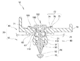
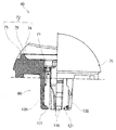
- reference numeral 10 denotes a fastening structure. Although the fastening structure 10 is not shown, a bumper (not shown) as an example of a part is attached to a base 20 which is a body of an automobile, for example, and a bumper retainer (not shown). ) To be fastened through a clip 30 constituting a part of.
- the base 20 is provided with a mounting hole 21 for mounting the clip 30 as shown in FIG.
- the mounting hole 21 penetrates the front and back surfaces of the base 20 and is formed in a non-circular shape, for example, a square shape.
- the mounting hole 21 is formed in a square shape, the present invention is not limited to this, and any non-circular shape that does not rotate the clip 30 may be used.
- the body of the car is exemplified as the base 20, but the present invention is not limited to this, and is not limited to the car, but may be other vehicles, buildings, furniture, office equipment, or the like.
- the bumper is exemplified as the part, but it is not limited to this. Further, the bumper retainer (not shown) and the clip 30 are also considered as a part of the part, and this point will be described later as a “part aspect”.
- the clip 30 is configured as a part of the bumper retainer, the clip 30 is not limited to this and may be configured separately from the bumper retainer. (Clip 30) As shown in FIG. 1 and FIG. 2, the clip 30 has the following configuration when roughly classified.
- Grommet 40 Pin 50 (3) Packing 60
- the configuration of the clip 30 is not limited to the above (1) to (3).
- the grommet 40 constitutes a part of a bumper retainer (not shown), is attached to the mounting hole 21 of the base 20, and a pin 50 described later is inserted into the base 20. It is concluded with respect to it.
- the bumper retainer is fastened to the base 20 via the grommet 40.
- the grommet 40 is integrally formed of a synthetic resin having appropriate elasticity and rigidity.
- the grommet 40 is configured as a part of the bumper retainer, the grommet 40 is not limited to this and may be configured separately from the bumper retainer.
- the grommet 40 has the following parts as shown in FIGS.
- each part of the grommet 40 is not limited to the above (1) and (2).
- the pin 50 As shown in FIGS. 1 to 4, the pin 50 is inserted into the grommet 40 to fasten the grommet 40 to the base 20.
- the pin 50 is integrally formed of a synthetic resin having appropriate elasticity and rigidity.
- the pin 50 has the following parts as shown in FIGS.
- each part of the grommet 40 is not limited to the above (1) and (2).
- Packing 60 As shown in FIG. 1, the packing 60 is located between the base 20 and the grommet 40 and prevents water from entering from the mounting hole 21 of the base 20.
- the packing 60 is formed of an elastic material, and is formed in, for example, a rectangular plate shape. In the center of the packing 60, a square center hole 61 that penetrates the front and back surfaces and that conforms to the outer shape of a leg portion 80 of the grommet 40 described later is formed.
- the hook-shaped portion 70 constitutes a part of a bumper retainer (not shown) and abuts against the base 20.
- the bowl-shaped portion 70 is formed in a disk shape having an oval plane, and its outer shape is set larger than the inner diameter of the mounting hole 21 of the base 20.
- the bowl-shaped part 70 was comprised as a part of bumper retainer, it is not limited to this, You may comprise separately from a bumper retainer.
- the hook-like portion 70 is brought into direct contact with the base 20; however, the present invention is not limited to this, and when configured separately from the bumper retainer, it is indirectly applied to the base 20 via the bumper retainer. You may make it contact.
- the bowl-shaped part 70 has the following parts as shown in FIGS.
- the through hole 71 is formed in a circular shape in the center of the bowl-shaped portion 70, and penetrates the front and back surfaces, that is, the vertical direction in FIG. (Wall 72)
- the wall portion 72 extends in the insertion direction of the pin 50 as shown in FIGS.
- the wall portion 72 is formed in a circular rib shape that is slightly larger around the through hole 71 and protrudes from the upper surface of the bowl-shaped portion 70.
- the wall 72 has a trapezoidal cross section with the inclined surface 74 facing the center of the through hole 71.
- the inclined surface 74 is located on the inner wall of the wall portion 72, more specifically, on the inner side surface, and is inclined downward toward the direction of the through hole 71.
- the top surface 75 which is the upper surface of the wall portion 72, is formed in parallel with the upper surface of the wall portion 72, and a connecting portion 76 is formed at the corner between the inclined surface 74 and the top surface 75. (Projection wall 73) As shown in FIGS.
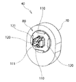
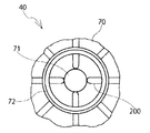
- the protruding wall 73 is located between the through hole 71 and the wall 72, and is formed on the lower side of the head 100 when a pin 50 described later is rotated. It abuts on the projection 103 and guides the shaft portion 90 of the pin 50 in the direction of coming out of the through hole 71.
- the projecting walls 73 protrude from the upper surface of the bowl-shaped portion 70, are formed in a symmetrical shape with respect to the front and rear in the circumferential direction of the bowl-shaped portion 70, and are formed in a radial pattern around the through hole 71. ing.
- Each projecting wall 73 has a flat surface formed in a “yaji” or “arrow” shape, and a pointed tip of the “yaji” or “arrow” at the tip is directed to the through hole 71.
- inclined surfaces 77, 77 are formed, which are positioned in the circumferential direction and inclined in a tapered manner.
- the protruding wall 73 comes into contact with a protruding portion 103 protruding from the lower surface of the head 100 of the pin 50 described later. That is, when the shaft portion 90 of the pin 50 is inserted deeply into the through hole 71 of the grommet 40, the protrusion 103 protruding from the lower surface of the head 100 is positioned on the upper surface of the bowl-shaped portion 70. When the pin 50 is rotated in this state, the projecting portion 103 comes into contact with the projecting wall 73 projecting from the upper surface of the bowl-shaped portion 70.
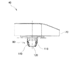
- the leg portion 80 hangs down from the periphery of the through hole 71 and engages with a hole in the mounting hole 21 provided in the base 20 by inserting the pin 50.
- a plurality of, for example, a total of four first and second leg pieces 110 and 120 are provided.
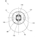
- the leg portion 80 is formed by arranging a total of four first and second leg pieces 110, 120 in a rectangular tube shape, and the inside of the tube communicates with the through hole 71. .
- leg pieces 110 and 120 Although a total of four leg pieces 110 and 120 are provided, the present invention is not limited to this, and at least a pair of leg pieces is sufficient.
- the outer shape of the leg portion 80 composed of the four first and second leg pieces 110 and 120 in total is substantially matched with the inner shape of the mounting hole 21 of the base 20.
- first leg pieces 110 and 120 are opposed to each other as shown in FIGS. Is provided with a rib-shaped first convex portion 111 extending vertically.
- the first leg piece 110 is inserted into the mounting hole 21 of the base 20, and the shaft portion 90 of the pin 50 described later is inserted through the through hole 71, thereby
- the grommet 40 is fixed to the mounting hole 21 of the base 20 by sandwiching the base 20 from the front and back surfaces between the lower surface of the bowl-shaped portion 70 and the pair of first leg pieces 110 that are expanded. That is, since the grommet 40 is configured as a part of a bumper retainer (not shown), the bumper retainer is fixed to the base 20.
- the two second leg pieces 120 are opposed to each other as shown in FIGS.
- a claw-like second convex portion 121 bent in an L-shaped cross section is provided on the facing inner surface.
- the second leg piece 120 is inserted into the mounting hole 21 of the base 20, and a pin portion 50, which will be described later, is inserted through the through hole 71, whereby the second leg piece 120 has its claws.
- the second convex portion 121 having a shape fits into a later-described concave portion 94 of the shaft portion 90 to prevent the pin 50 from moving in the insertion direction of the shaft portion 90.
- shaft 90 As shown in FIGS. 15 to 18, the shaft portion 90 hangs down from a head 100 described later.
- the head 100 hangs down from the lower surface of the head 100, and the whole is formed in a substantially quadrangular prism shape, and the tip is pointed in a tapered shape.
- the shaft portion 90 has the following portions as shown in FIGS.
- Each part of the shaft part 90 is not limited to the following (1) to (6).
- Large diameter part 91 As shown in FIGS. 15 to 18, the large-diameter portion 91 is located in the middle of the length of the shaft portion 90 and is set to a relatively large diameter.
- the large diameter portion 91 is inserted into the space between the first leg pieces 110 when the shaft portion 90 of the pin 50 is inserted into the hollow portion of the leg portion 80 through the through hole 71. Then, the first leg piece 110 is expanded.
- Narrow diameter part 92 As shown in FIGS. 15 to 18, the small-diameter portion 92 is located at the distal end portion of the shaft portion 90 and has a smaller diameter than the large-diameter portion 91.
- the first leg piece 110 does not expand at the position where the small diameter portion 92 has entered the space between the first leg pieces 110.
- Cam part 93 As shown in FIGS. 15 to 18, the cam portion 93 is located between the large diameter portion 91 and the small diameter portion 92, and gradually increases from the small diameter portion 92 toward the large diameter portion 91.
- the recess 94 is formed in the large diameter portion 91 and is recessed in a concave shape.
- the claw-like second convex portion 121 of the second leg piece 120 is fitted into the concave portion 94, thereby preventing the axial portion 90 of the pin 50 from moving in the axial direction with respect to the grommet 40. To do.
- Stopper 95 As shown in FIGS. 15 to 18, the retaining portion 95 is adjacent to the small-diameter portion 92, is located at the tip portion of the shaft portion 90, is thicker than the small-diameter portion 92, and projects in an umbrella shape or a conical shape. Yes.
- the retaining portion 95 contacts the rib-shaped first convex portion 111 of the first leg piece 110, and The leg piece 110 is pushed open to pass through the interval between the first convex portions 111.
- the retaining portion 95 passes through the space between the first convex portions 111, the first leg piece 110 is restored by the restoring force of the resin, thereby preventing the shaft portion 90 from coming off.
- the retaining portion 95 abuts against the claw-shaped second convex portion 121 of the second leg piece 120 and passes through the interval of the second convex portion 121 so as to push open the second leg piece 120.
- the retaining portion 95 passes through the interval between the second convex portions 121, the second leg piece 120 is restored by the restoring force of the resin, thereby preventing the shaft portion 90 from coming off.
- Guide rib 96 As shown in FIGS. 15 to 18, a total of four guide ribs 96 extend radially from the center of the shaft portion 90, and are formed along the axial direction of the shaft portion 90.
- the guide rib 96 is inserted into the gap between the adjacent first leg piece 110 and the second leg piece 120 when the shaft part 90 of the pin 50 is inserted into the hollow part of the leg part 80 through the through hole 71.
- the shaft portion 90 of the pin 50 in the hollow inside of the leg portion 80 is prevented from being inadvertently rotated.
- the head 100 projects in a disc shape from the upper end of the shaft portion 90, and the outer diameter thereof is set larger than the inner diameter of the through hole 71.
- the head 100 has the following parts as shown in FIGS.
- Each part of the head 100 is not limited to the following (1) to (3).
- the flange 101 As shown in FIGS. 17 and 18, the flange 101 has a thin wall shape extending straight from the outer periphery of the head 100.
- the flange 101 extends in an annular shape from the lower side of the head 100.
- the flange 101 is set to 1/8 of 0.25 mm when the thickness of the head 100 is 2 mm, for example.
- the flange 101 comes into contact with a protruding wall 73 protruding from the upper surface of the bowl-shaped portion 70 of the grommet 40. That is, when the shaft portion 90 of the pin 50 is inserted into the through hole 71 of the grommet 40, the lower surface of the flange 101 comes into contact with the top surface 75 that is the upper surface of the wall portion 72 protruding from the upper surface of the bowl-shaped portion. When the shaft portion 90 is inserted further deeply, the lower surface of the flange 101 is pushed by the angular connection portion 76 between the top surface 75 and the inclined surface 74 located on the inner side surface of the wall portion 72, and FIG. As shown in FIG. 4, it will be in the state of reverse warping.
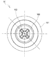
- the jig engaging portion 102 is engaged with a jig such as a “+” (plus) driver, and is provided with, for example, a + (plus) groove.
- the driver was illustrated as a jig
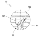
- the protrusion 103 is located below the head 100, protrudes outward in the radial direction from the outer periphery of the shaft portion 90, and has at least one inclined surface 104. Is.
- the protrusion 103 is formed in a triangular prism shape, and the inclined surface 104 faces the outer peripheral direction of the shaft portion 90.
- a pair of protrusions 103 are formed in the diameter direction of the shaft 90.
- the present invention is not limited thereto, and a single protrusion or three or more protrusions 103 may be formed.
- one inclined surface 104 is formed on one side of the head 100 in the circumferential direction, the present invention is not limited to this, but two inclined surfaces are formed on both sides of the head 100 in the circumferential direction.
- the protrusion 103 may be formed symmetrically with respect to the front and rear in the circumferential direction of the head 100.
- the projecting portion 103 comes into contact with a projecting wall 73 projecting from the upper surface of the bowl-shaped portion 70 of the grommet 40. That is, when the shaft portion 90 of the pin 50 is inserted deeply into the through hole 71 of the grommet 40, the protrusion 103 protruding from the lower surface of the head 100 is positioned on the upper surface of the bowl-shaped portion 70. When the pin 50 is rotated in this state, the projecting portion 103 comes into contact with the projecting wall 73 projecting from the upper surface of the bowl-shaped portion 70.
- the pin 50 and the packing 60 are assembled to the grommet 40 in advance.
- the pin 50 and the packing 60 may be attached.
- the leg portion 80 of the grommet 40 is inserted in alignment with the center hole 61 of the packing 60, and the packing 60 is positioned below the lower surface of the bowl-shaped portion 70.
- the shaft portion 90 of the pin 50 When the shaft portion 90 of the pin 50 is inserted, the shaft portion 90 of the pin 50 is inserted into the hollow inside of the leg portion 80 through the through hole 71. Thereafter, the retaining portion 95 at the tip of the shaft 90 abuts against the first convex portion 111 of the first leg piece 110 and the second convex portion 121 of the second leg piece 120, and The two convex portions 121 are pushed open so as to pass through the interval between the first convex portions 111 and the second convex portion 121, and the first convex portion 111 and the second convex portion 121 are connected to the shaft portion. It is located in 90 narrow diameter portions 92. For this reason, the shaft portion 90 cannot be removed from the hollow interior of the leg portion 80, and the pin 50 is temporarily fixed to the grommet 40.
- the shaft portion 90 advances in the hollow portion of the leg portion 80, and the first leg piece 110 of the grommet 40 is pushed open by the large diameter portion 91, so that the grommet 40 is shown in FIG.
- the outer diameter of the leg portion 80 is expanded.
- the grommet 40 is fixed to the mounting hole 21 of the base 20 by sandwiching the base 20 from the front and back surfaces between the lower surface of the bowl-shaped portion 70 and the pair of first leg pieces 110 that are expanded. That is, since the grommet 40 is configured as a part of a bumper retainer (not shown), the bumper retainer is fixed to the base 20.
- the claw-like second convex portion 121 of the second leg piece 120 of the grommet 40 fits in the concave portion 94 of the pin 50, so that the shaft portion 90 of the pin 50 is inserted in the insertion direction. Movement is prevented.
- the flange 101 of the pin 50 abuts against a protruding wall 73 protruding from the upper surface of the flange 70 of the grommet 40. That is, when the shaft portion 90 of the pin 50 is inserted into the through hole 71 of the grommet 40, the lower surface of the flange 101 comes into contact with the top surface 75 that is the upper surface of the wall portion 72 protruding from the upper surface of the bowl-shaped portion. When the shaft portion 90 is inserted further deeply, the lower surface of the flange 101 is pushed by the angular connection portion 76 between the top surface 75 and the inclined surface 74 located on the inner side surface of the wall portion 72, and reversely warps.
- a jig such as a “+” (plus) screwdriver is engaged with the jig engaging portion 102 which is the + (plus) groove of the pin 50, and the head 100 of the pin 50 is moved in one direction, for example, Rotate counterclockwise.
- the inclined surface 104 of the projection 103 and the inclined surface 77 of either one of the inclined surfaces 77 and 77 on both sides of the protruding wall 73 are obtained.
- the head 100 of the pin 50 is guided in the direction of rising from the upper surface of the flange 70 of the grommet 40.
- the second leg of the grommet 40 fitted in the concave portion 94 of the shaft portion 90 is moved by moving the shaft portion 90 in the direction of passing through the hollow interior of the leg portion 80, that is, upward.
- the claw-like second convex portion 121 of the piece 120 is engaged and disengaged. For this reason, when the first leg piece 110 of the grommet 40 moves from the large diameter portion 91 of the shaft portion 90 to the small diameter portion 92, the outer diameter of the leg portion 80 of the grommet 40 is reduced.
- the leg 80 of the grommet 40 can be pulled out from the mounting hole 21 of the base 20.
- the first part is composed of a bumper retainer and a part of the grommet 40, that is, a bowl-shaped portion 70.
- the grommets 40 may be omitted, and the through holes 71 and the wall portions 72 of the grommets 40 may be formed in the bumper retainer.
- a bumper retainer was illustrated as a part of components, it is not limited to this.
- the first part is fastened to the base 20 in cooperation with the fastening member.
- the fastening member includes a pin 50 and another part of the grommet 40, that is, a leg 80.
- the leg part 80 of the grommet 40 is an example of an engaging means.
- the engaging means is integrated with the shaft portion 90 of the pin 50, is provided at the lower portion of the flange 101, and fixes the base 20 and the first component.
- leg part 80 of the grommet 40 is illustrated as an engaging means, it is not limited to this, although not shown in figure, the grommet 40 may be omitted and the engaging means may be provided in the pin 50, for example, the shaft of the pin 50 A so-called anchor-type elastic claw may be formed at the tip of the portion 90.
- the second part is composed of a bumper retainer and the entire grommet 40.
- the bumper retainer (not shown) and the grommet 40 are illustrated as the second parts, the invention is not limited to this, but the grommet 40 may be omitted and the bumper retainer alone may be configured. Moreover, although a bumper retainer was illustrated as a part of components, it is not limited to this.
- the third part is composed of a bumper retainer excluding the grommet 40, although not shown.
- the bumper retainer which is the third part, is fastened in a state of being superposed on the base 20 via a clip 30 composed of a grommet 40 and a pin 50 (not shown).
- the bumper retainer has been illustrated as the third component, it is not limited to this. (Second Embodiment) Next, a second embodiment of the present invention will be described with reference to FIG.
- the feature of this embodiment is that the protruding wall 200 protruding from the upper surface of the bowl-shaped portion 70 of the grommet 40 is formed into an ellipse on a plane as shown in FIG.
- the oval protruding wall 200 has a symmetrical shape with respect to the front and rear in the circumferential direction of the bowl-shaped portion 70.
- the feature of this embodiment is that the protruding wall 210 protruding from the upper surface of the bowl-shaped portion 70 of the grommet 40 is formed in a rectangular shape on a plane as shown in FIG.
- the rectangular protruding wall 210 has a symmetrical shape with respect to the circumferential direction of the bowl-shaped portion 70.
- the projecting wall 73 is formed in a “finger” or “arrow” shape on a plane
- the projecting wall 200 is formed in an ellipse in a plane
- the projecting wall 210 is formed in a rectangle in the plane, but the projecting walls 73, 200, 210 are front and rear in the circumferential direction of the bowl-shaped portion 70.
- the shape is not limited to these shapes.
- the feature of the present embodiment is that the wall portion 400 protruding from the upper surface of the flange 70 of the grommet 40 is the first embodiment described above with reference to FIGS.
- the wall portion 72 of this form is not a rib shape but a step shape.
- the wall portion 400 includes an inclined surface 401 that is inclined obliquely upward in the outer peripheral direction from the upper surface of the bowl-shaped portion 70, a top surface 402 that is an upper surface of the wall portion 400, and between the inclined surface 401 and the top surface 402.
- the connecting portion 403 is located at the corner.
Landscapes
- Engineering & Computer Science (AREA)
- General Engineering & Computer Science (AREA)
- Mechanical Engineering (AREA)
- Insertion Pins And Rivets (AREA)
- Connection Of Plates (AREA)
Abstract
Description
(1)頭部
(2)軸部
軸部(90)は、頭部から垂下するものである。
フランジは、頭部の外周からストレート形状に延びる薄肉状のものである。
係合手段(例えばグロメットの脚部)は、軸部と一体となり、フランジの下部に設けられ、ベースと部品(例えばバンパーリテーナー)を固定するものである。
貫通孔は、締結部材の軸部が挿通するものである。
壁部は、貫通孔の外周に位置し、軸部の挿入方向に向かって延びるものである。
本発明の第1観点による部品の締結構造において、締結部材の係合手段は、ベースに設けられた取付穴に挿通する際に、内側に撓み、当該取付穴を挿通後、ベースの裏側で係止する複数の脚片を有する脚部から構成されていてもよい。この場合、係合手段を複数の脚片を有する脚部から構成することにより、ベースに部品をワンタッチで係止することができる。
本発明の第2観点による部品の締結構造は、次の点を特徴とする。
(2)軸部
軸部は、頭部から垂下するものである。
フランジは、頭部の外周からストレート形状に延びる薄肉状のものである。
貫通孔は、ピンの軸部が挿通するものである。
脚部は、貫通孔の周囲から垂下するとともに、ピンの挿入によって、ベースに設けられた取付穴の孔淵に係合する複数の脚片を有するものである。
壁部は、ピンの挿入方向に向かって延びるものである。
本発明の第3観点による部品締結用のクリップは、本発明の第1観点又は第2観点による部品の締結構造に用いるクリップであって、次の点を特徴とする。
(2)軸部
軸部は、頭部から垂下するものである。
フランジは、頭部の外周からストレート形状に延びる薄肉状のものである。
鍔状部は、第3の部品(例えばバンパーリテーナー)の一部を構成するととともに、ベースに当接するものである。
貫通孔は、鍔状部に設けられ、ピンの軸部が挿通するものである。
脚部は、貫通孔の周囲から垂下するとともに、ピンの挿入によって、ベースに設けられた取付穴の孔淵に係合する複数の脚片を有するものである。
本発明の第2観点による部品の締結構造において、フランジの軸先端側の側面が、壁部の内壁(例えば傾斜面)と頂面との接続部に圧接してもよい。この場合、フランジの軸先端側の側面を、壁部の内壁と頂面との接続部に圧接させることができる。その結果、面圧が高くなり、良好な止水性を保持できる。
本発明の第1観点及び第2観点による部品の締結構造において、壁部の内側側面は、貫通孔の方向に向かって下り傾斜した傾斜面となってもよい。この場合、フランジと常に圧接させることが可能であって、製造のバラツキによるシール性能の低下を抑制することができ、フランジの滑落を防ぐことができる。
本発明の第3観点による部品締結用クリップにおいて、フランジの軸先端側の側面が、壁部の内壁(例えば傾斜面)と頂面との接続部に圧接してもよい。この場合、フランジの軸先端側の側面を、壁部の内壁と頂面との接続部に圧接させることができる。
本発明の第3観点による部品締結用クリップにおいて、壁部の内側側面は、貫通孔の方向に向かって下り傾斜した傾斜面となってもよい。この場合、フランジと常に圧接させることが可能であって、製造のバラツキによるシール性能の低下を抑制することができる。
本発明の第1観点による部品の締結構造によれば、締結部材の係合手段により、ベースと部品を固定することができる。
本発明の第2観点による部品の締結構造によれば、第2の部品に有する複数の脚片を有する脚部により、当該部品をベースに対して係合させることができる。
本発明の第3観点による部品締結用のクリップによれば、グロメットに有する複数の脚片を有する脚部により、当該グロメットを介して第3の部品をベースに対して係合させることができる。
図1中、10は、締結構造を示し、締結構造10は、図示しないが、例えば自動車のボディーであるベース20に、部品の一例であるバンパー(図示せず)を、バンパーリテーナー(図示せず)の一部を構成するクリップ30を介して締結するものである。
(クリップ30)
クリップ30は、図1及び図2に示すように、大別すると、次の構成を備える。
(2)ピン50
(3)パッキング60
なお、クリップ30の構成は、上記した(1)~(3)に限定されない。
(グロメット40)
グロメット40は、図1~4に示すように、バンパーリテーナー(図示せず)の一部を構成し、ベース20の取付穴21に取り付けられ、後述するピン50を挿入することで、ベース20に対して締結されるものである。バンパーリテーナーは、グロメット40を介してベース20に対して締結される。グロメット40は、適度な弾性と剛性とを有する合成樹脂により一体的に成形されている。
(2)脚部80
なお、グロメット40の各部は、上記した(1)及び(2)に限定されない。
(ピン50)
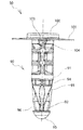
ピン50は、図1~4に示すように、グロメット40に挿入されることで、グロメット40をベース20に対して締結するものである。ピン50は、適度な弾性と剛性とを有する合成樹脂により一体的に成形されている。
(2)頭部100
なお、グロメット40の各部は、上記した(1)及び(2)に限定されない。
(パッキング60)
パッキング60は、図1に示すように、ベース20とグロメット40との間に位置し、ベース20の取付穴21からの水の浸入を防止するためのものである。パッキング60は、弾性に富む材質により形成され、例えば方形の板状に形成されている。パッキング60の中央には、表裏面に貫通し、後述するグロメット40の脚部80の外形に適合した方形の中心孔61を形成している。
(鍔状部70)
鍔状部70は、図1~4に示すように、バンパーリテーナー(図示せず)の一部を構成するととともに、ベース20に当接するものである。
(2)壁部72
(3)突壁73
なお、鍔状部70の各部は、上記した(1)~(3)に限定されない。
(貫通孔71)
貫通孔71は、図1~4に示すように、ピン50の軸部90が挿通するものである。
(壁部72)
壁部72は、図1~4に示すように、ピン50の挿入方向に向かって延びるものである。
(突壁73)
突壁73は、図2及び図22に示すように、貫通孔71と壁部72と間に位置し、後述するピン50を回転させた際に、その頭部100の下側に形成された突部103に当接し、ピン50の軸部90が貫通孔71から抜ける方向に案内するものである。
(脚部80)
脚部80は、図3、図4及び図8に示すように、貫通孔71の周囲から垂下するとともに、ピン50の挿入によって、ベース20に設けられた取付穴21の孔淵に係合する複数、例えば計4個の第1、第2脚片110,120を有するものである。脚部80は、図8及び図12に示すように、計4個の第1、第2脚片110,120を角筒形に配置して形成し、当該筒内部は貫通孔71に連通している。
(軸部90)
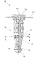
軸部90は、図15~18に示すように、後述する頭部100から垂下するものである。
太径部91は、図15~18に示すように、軸部90の長さの途中に位置し、比較的、太径に設定されている。
細径部92は、図15~18に示すように、軸部90の先端部に位置し、太径部91と比較して細径に設定されている。
カム部93は、図15~18に示すように、太径部91と細径部92との間に位置し、細径部92から太径部91に向かって徐々に太くなっている。
凹部94は、図15~18に示すように、太径部91に形成され、凹状に凹んでいる。
抜止部95は、図15~18に示すように、細径部92に隣接し、軸部90の先端部に位置し、細径部92より太く、先細状に傘形或いは円錐形に張り出している。
ガイドリブ96は、図15~18に示すように、軸部90の中心から放射状に計4個延び、軸部90の軸方向に沿って形成されている。
(頭部100)
頭部100は、軸部90の上端部から円盤状に張り出し、その外径を貫通孔71の内径より大きく設定している。
フランジ101は、図17及び図18に示すように、頭部100の外周からストレート形状に延びる薄肉状のものである。
治具係合部102は、図示しないが、例えば「+」(プラス)のドライバー等の治具と係合するものであり、例えば+(プラス)溝を設けている。
突部103は、図15、図17及び図20に示すように、頭部100の下側に位置し、軸部90の外周からその半径方向外向きに突出し、少なくとも一つの傾斜面104を有するものである。
(クリップ30の取付方法)
つぎに、上記した構成を有するグロメット40とピン50とからなるクリップ30の取付方法について説明する。
(クリップ30の取外方法)
一方、取り付けたクリップ30の取外方法について、説明する。
(部品の態様)
つぎに、部品の態様について説明する。
第1の部品は、図示しないが、バンパーリテーナーと、グロメット40の一部、すなわち鍔状部70とから構成される。
第2の部品は、図示しないが、バンパーリテーナーと、グロメット40の全部とから構成される。
第3の部品は、図示しないが、グロメット40を除く、バンパーリテーナーから構成される。
(第2の実施の形態)
つぎに、図23を用いて、本発明の第2の実施の形態について説明する。
(第3の実施の形態)
つぎに、図24を用いて、本発明の第3の実施の形態について説明する。
(第4の実施の形態)
つぎに、図25及び図26を用いて、本発明の第4の実施の形態について説明する。
Claims (8)
- ベースに部品を締結する締結構造において、
前記締結構造には、
頭部と、
前記頭部から垂下する軸部と、
前記頭部の外周からストレート形状に延びる薄肉状のフランジと、
前記軸部と一体となり、前記フランジの下部に設けられ、前記ベースと前記部品を固定する係合手段とを有する締結部材を備え、
前記部品には、
前記締結部材の前記軸部が挿通する貫通孔と、
前記貫通孔の外周に位置し、前記軸部の挿入方向に向かって延びる壁部とを有し、
前記ベースには、
前記軸部が挿入可能な取付穴を有し、
前記軸部の挿入によって前記ベースと前記部品とが締結される際に、前記フランジが前記壁部に圧接され、逆反りした状態となることを特徴とする部品の締結構造。 - ベースに第2の部品を締結する締結構造において、
前記締結構造には、
頭部と、
前記頭部から垂下する軸部と、
前記頭部の外周からストレート形状に延びる薄肉状のフランジとを有するピンを備え、
前記第2の部品には、
前記ピンの前記軸部が挿通する貫通孔と、
前記貫通孔の周囲から垂下するとともに、前記ピンの挿入によって、前記ベースに設けられた取付穴の孔淵に係合する複数の脚片を有する脚部と、
前記ピンの挿入方向に向かって延びる壁部とを有し、
前記ピンの挿入によって前記ベースと前記第2の部品とが締結される際に、前記フランジが前記壁部と圧接され、逆反りした状態となることを特徴とする部品の締結構造。 - ベースに第3の部品を締結するクリップにおいて、
前記クリップには、
頭部、
前記頭部から垂下する軸部、
前記頭部の外周からストレート形状に延びる薄肉状のフランジからなるピンと、
第3の部品の一部を構成するととともに、前記ベースに当接する鍔状部、
前記鍔状部に設けられ、前記ピンの前記軸部が挿通する貫通孔、
前記貫通孔の周囲から垂下するとともに、前記ピンの挿入によって、前記ベースに設けられた取付穴の孔淵に係合する複数の脚片を有する脚部からなるグロメットとを備え、
前記グロメットの鍔状部には、
前記軸部の挿入方向に向かって延びる壁部を有し、
前記ピンの挿入によって前記ベースと前記第3の部品とが締結される際に、前記フランジが前記壁部と圧接され、逆反りした状態となることを特徴とする部品締結用のクリップ。 - 請求項1に記載の締結構造であって、
前記締結部材の前記係合手段は、
前記ベースに設けられた取付穴に挿通する際に、内側に撓み、当該取付穴を挿通後、前記ベースの裏側で係止する複数の脚片を有する脚部から構成されていることを特徴とする部品の締結構造。 - 請求項1又は請求項2に記載の締結構造であって、
前記フランジの軸先端側の側面が、
前記壁部の内壁と頂面との接続部に圧接することを特徴とする部品の締結構造。 - 請求項1又は請求項2に記載の締結構造であって、
前記壁部の内側側面は、
前記貫通孔の方向に向かって下り傾斜した傾斜面となっていることを特徴とする部品の締結構造。 - 請求項3に記載のクリップであって、
前記フランジの軸先端側の側面が、
前記壁部の内壁と頂面との接続部に圧接することを特徴とする部品締結用のクリップ。 - 請求項3に記載のクリップであって、
前記壁部の内側側面は、
前記貫通孔の方向に向かって下り傾斜した傾斜面となっていることを特徴とする部品締結用のクリップ。
Priority Applications (4)
| Application Number | Priority Date | Filing Date | Title |
|---|---|---|---|
| CN201180014996.6A CN102822539B (zh) | 2010-03-24 | 2011-03-23 | 部件紧固结构以及其所使用的卡夹 |
| EP11759450.7A EP2551535B1 (en) | 2010-03-24 | 2011-03-23 | Part fastening structure and clip using same |
| US13/636,570 US8882421B2 (en) | 2010-03-24 | 2011-03-23 | Fastening structure for part and clip used therein |
| BR112012024141A BR112012024141B1 (pt) | 2010-03-24 | 2011-03-23 | estrutura de fixação para parte e clipe usados nela |
Applications Claiming Priority (2)
| Application Number | Priority Date | Filing Date | Title |
|---|---|---|---|
| JP2010068215A JP5319586B2 (ja) | 2010-03-24 | 2010-03-24 | 部品の締結構造及びこれに用いるクリップ |
| JP2010-068215 | 2010-03-24 |
Publications (1)
| Publication Number | Publication Date |
|---|---|
| WO2011118645A1 true WO2011118645A1 (ja) | 2011-09-29 |
Family
ID=44673195
Family Applications (1)
| Application Number | Title | Priority Date | Filing Date |
|---|---|---|---|
| PCT/JP2011/057015 Ceased WO2011118645A1 (ja) | 2010-03-24 | 2011-03-23 | 部品の締結構造及びこれに用いるクリップ |
Country Status (7)
| Country | Link |
|---|---|
| US (1) | US8882421B2 (ja) |
| EP (1) | EP2551535B1 (ja) |
| JP (1) | JP5319586B2 (ja) |
| CN (1) | CN102822539B (ja) |
| BR (1) | BR112012024141B1 (ja) |
| PL (1) | PL2551535T3 (ja) |
| WO (1) | WO2011118645A1 (ja) |
Families Citing this family (10)
| Publication number | Priority date | Publication date | Assignee | Title |
|---|---|---|---|---|
| JP5379068B2 (ja) * | 2010-04-27 | 2013-12-25 | 株式会社ニフコ | 部材締結構造 |
| US9038876B2 (en) * | 2013-04-08 | 2015-05-26 | Ford Global Technologies, Llc | Radar mounting device |
| US9528540B2 (en) | 2014-08-12 | 2016-12-27 | Newfrey Llc | Insertion-locking pin and grommet and related methods |
| JP6446741B2 (ja) | 2015-03-10 | 2019-01-09 | ポップリベット・ファスナー株式会社 | 留め具及び締結構造 |
| JP6796037B2 (ja) * | 2017-07-13 | 2020-12-02 | 本田技研工業株式会社 | 駆動回路ユニット |
| JP6850773B2 (ja) * | 2018-08-22 | 2021-03-31 | 株式会社ニフコ | クリップ |
| US10900513B2 (en) | 2019-04-02 | 2021-01-26 | Newfrey Llc | Re-usable one-push pin and grommet fastener |
| US20220065281A1 (en) * | 2020-09-03 | 2022-03-03 | Milbank Manufacturing Co. | Plumb adjuster for electrical enclosure |
| US12326163B2 (en) | 2022-09-07 | 2025-06-10 | Newfrey Llc | Pin and grommet fastener including pin and grommet having panel retention fingers and pin retention fingers that cooperate with one another to define pin receptacle for receiving the pin |
| WO2026062961A1 (ja) * | 2024-09-20 | 2026-03-26 | 株式会社パイオラックス | 留め具 |
Citations (3)
| Publication number | Priority date | Publication date | Assignee | Title |
|---|---|---|---|---|
| JPH0814231A (ja) * | 1994-06-28 | 1996-01-16 | Piolax Inc | 止め具 |
| JPH081090U (ja) | 1995-03-31 | 1996-07-02 | 株式会社ニフコ | クリップ |
| JP2006226368A (ja) | 2005-02-16 | 2006-08-31 | Nifco Inc | クリップ |
Family Cites Families (13)
| Publication number | Priority date | Publication date | Assignee | Title |
|---|---|---|---|---|
| US4674930A (en) * | 1981-12-14 | 1987-06-23 | Hartwell Corporation | Stand-off fastener |
| JP2578069Y2 (ja) * | 1991-03-11 | 1998-08-06 | 株式会社 ニフコ | グロメット |
| JPH0640428U (ja) * | 1992-10-29 | 1994-05-31 | 株式会社ニフコ | プッシュリベット |
| JP3251775B2 (ja) * | 1994-06-15 | 2002-01-28 | 株式会社ニフコ | クリップ |
| JP3195165B2 (ja) | 1994-06-15 | 2001-08-06 | 三洋化成工業株式会社 | 密着性向上方法 |
| WO1996017178A1 (en) * | 1994-12-02 | 1996-06-06 | Donnelly Corporation | Mounting clip |
| JP3539643B2 (ja) * | 1994-12-27 | 2004-07-07 | 株式会社ニフコ | ピングロメット |
| US5975820A (en) * | 1998-11-03 | 1999-11-02 | Illinois Tool Works Inc. | Two-piece pin and grommet |
| JP2003222113A (ja) * | 2002-01-29 | 2003-08-08 | Nippon Pop Rivets & Fasteners Ltd | クリップ |
| JP4091859B2 (ja) * | 2003-03-03 | 2008-05-28 | 株式会社パイオラックス | 締結具 |
| FR2882797B1 (fr) * | 2005-03-02 | 2007-05-25 | Itw De France Soc Par Actions | Attache adaptee a etre fixee dans une cavite de contour predetermine |
| US7614836B2 (en) * | 2006-05-09 | 2009-11-10 | Gm Global Technology Operations, Inc. | Arrangements for attaching components to surfaces |
| JP2009008249A (ja) * | 2007-05-30 | 2009-01-15 | Piolax Inc | 2ピースクリップ |
-
2010
- 2010-03-24 JP JP2010068215A patent/JP5319586B2/ja active Active
-
2011
- 2011-03-23 WO PCT/JP2011/057015 patent/WO2011118645A1/ja not_active Ceased
- 2011-03-23 US US13/636,570 patent/US8882421B2/en active Active
- 2011-03-23 PL PL11759450T patent/PL2551535T3/pl unknown
- 2011-03-23 CN CN201180014996.6A patent/CN102822539B/zh active Active
- 2011-03-23 EP EP11759450.7A patent/EP2551535B1/en active Active
- 2011-03-23 BR BR112012024141A patent/BR112012024141B1/pt active IP Right Grant
Patent Citations (3)
| Publication number | Priority date | Publication date | Assignee | Title |
|---|---|---|---|---|
| JPH0814231A (ja) * | 1994-06-28 | 1996-01-16 | Piolax Inc | 止め具 |
| JPH081090U (ja) | 1995-03-31 | 1996-07-02 | 株式会社ニフコ | クリップ |
| JP2006226368A (ja) | 2005-02-16 | 2006-08-31 | Nifco Inc | クリップ |
Also Published As
| Publication number | Publication date |
|---|---|
| BR112012024141A2 (pt) | 2016-06-28 |
| EP2551535B1 (en) | 2017-06-07 |
| EP2551535A4 (en) | 2016-03-30 |
| US8882421B2 (en) | 2014-11-11 |
| CN102822539A (zh) | 2012-12-12 |
| JP2011202692A (ja) | 2011-10-13 |
| JP5319586B2 (ja) | 2013-10-16 |
| CN102822539B (zh) | 2015-01-28 |
| EP2551535A1 (en) | 2013-01-30 |
| PL2551535T3 (pl) | 2017-11-30 |
| BR112012024141B1 (pt) | 2020-04-14 |
| US20130039717A1 (en) | 2013-02-14 |
Similar Documents
| Publication | Publication Date | Title |
|---|---|---|
| JP5319586B2 (ja) | 部品の締結構造及びこれに用いるクリップ | |
| JP5379068B2 (ja) | 部材締結構造 | |
| JP6227780B2 (ja) | 止め具 | |
| JP5036872B2 (ja) | 止め具 | |
| JP6446741B2 (ja) | 留め具及び締結構造 | |
| JP5243914B2 (ja) | ホールプラグ | |
| JP5653400B2 (ja) | クリップ | |
| JP2009008249A (ja) | 2ピースクリップ | |
| JP5210329B2 (ja) | クリップ | |
| JP4091859B2 (ja) | 締結具 | |
| GB2413595A (en) | Clip | |
| US20160223003A1 (en) | Clip | |
| JP5084641B2 (ja) | クリップ | |
| JP2017096449A (ja) | クリップ | |
| JP5134204B2 (ja) | グロメット | |
| JP2020034024A (ja) | 留め具 | |
| JP5947321B2 (ja) | バンパ取付構造 | |
| JP5726849B2 (ja) | クリップ | |
| JPH0741026U (ja) | クリップ | |
| JP2020063831A (ja) | 取付具 | |
| JP2006125571A (ja) | クリップ | |
| JP2015230016A (ja) | 車両用部材の取付構造 | |
| JP2013113368A (ja) | クリップ |
Legal Events
| Date | Code | Title | Description |
|---|---|---|---|
| WWE | Wipo information: entry into national phase |
Ref document number: 201180014996.6 Country of ref document: CN |
|
| 121 | Ep: the epo has been informed by wipo that ep was designated in this application |
Ref document number: 11759450 Country of ref document: EP Kind code of ref document: A1 |
|
| NENP | Non-entry into the national phase |
Ref country code: DE |
|
| WWE | Wipo information: entry into national phase |
Ref document number: 1201004895 Country of ref document: TH Ref document number: 2768/KOLNP/2012 Country of ref document: IN |
|
| REEP | Request for entry into the european phase |
Ref document number: 2011759450 Country of ref document: EP |
|
| WWE | Wipo information: entry into national phase |
Ref document number: 2011759450 Country of ref document: EP |
|
| WWE | Wipo information: entry into national phase |
Ref document number: 13636570 Country of ref document: US |
|
| REG | Reference to national code |
Ref country code: BR Ref legal event code: B01A Ref document number: 112012024141 Country of ref document: BR |
|
| ENP | Entry into the national phase |
Ref document number: 112012024141 Country of ref document: BR Kind code of ref document: A2 Effective date: 20120924 |