WO2012105603A1 - 緯糸張力付与装置 - Google Patents
緯糸張力付与装置 Download PDFInfo
- Publication number
- WO2012105603A1 WO2012105603A1 PCT/JP2012/052254 JP2012052254W WO2012105603A1 WO 2012105603 A1 WO2012105603 A1 WO 2012105603A1 JP 2012052254 W JP2012052254 W JP 2012052254W WO 2012105603 A1 WO2012105603 A1 WO 2012105603A1
- Authority
- WO
- WIPO (PCT)
- Prior art keywords
- weft
- passage
- tension applying
- deformed
- gripping
- Prior art date
- Legal status (The legal status is an assumption and is not a legal conclusion. Google has not performed a legal analysis and makes no representation as to the accuracy of the status listed.)
- Ceased
Links
Images








Classifications
-
- D—TEXTILES; PAPER
- D03—WEAVING
- D03D—WOVEN FABRICS; METHODS OF WEAVING; LOOMS
- D03D47/00—Looms in which bulk supply of weft does not pass through shed, e.g. shuttleless looms, gripper shuttle looms, dummy shuttle looms
- D03D47/28—Looms in which bulk supply of weft does not pass through shed, e.g. shuttleless looms, gripper shuttle looms, dummy shuttle looms wherein the weft itself is projected into the shed
- D03D47/30—Looms in which bulk supply of weft does not pass through shed, e.g. shuttleless looms, gripper shuttle looms, dummy shuttle looms wherein the weft itself is projected into the shed by gas jet
- D03D47/3066—Control or handling of the weft at or after arrival
- D03D47/308—Stretching or holding the weft
Definitions
- the present invention relates to a weft tension applying device that applies tension to a weft thread inserted.
- the weft tension applying device in order to apply an appropriate tension to the weft, for example, there is a device that captures the weft by blowing air from a stretch nozzle into the weft capturing pipe (see, for example, Japanese Patent Laid-Open No. 10-204751). ).
- the injection of the stretch nozzle is started before the front end of the weft reaches the weft introduction recess on the opening side of the weft catching pipe, and is stopped just before the beating.
- the present invention has an object to obtain a weft tension applying device capable of applying an appropriate tension to a weft while suppressing air consumption in consideration of the above facts.
- the weft tension applying device is arranged on the downstream side in the weft insertion direction of the weft with respect to the weft insertion passage of the deformed kite and is fixed on the sley, and is surrounded by a wall surface.
- an insertion passage through which the tip of the weft inserted is inserted, a pressing member capable of gripping the tip of the weft between the inner surface of the insertion passage, and the weft by operating the pressing member
- An air cylinder mechanism that grips the tip of the weft, and a weft gripping mechanism that is fixed to the loom frame and is gripped by the weft gripping mechanism by the tip of the weft and in the strike direction of the deformed wrinkle
- a tension applying member that is in contact with the weft between the deformed scissors and the weft holding mechanism and applies a tension to the weft by relative displacement with the deformed scissors.
- the weft gripping mechanism portion is disposed on the downstream side in the weft insertion direction of the deformed kite with respect to the weft insertion passage of the deformed kite and is fixed on the sley. .
- this weft gripping mechanism portion an insertion path surrounded by a wall surface is formed, the tip of the weft thread inserted is inserted into the insertion path, and the pressing member inserts the tip of the weft thread into the inner surface of the insertion path.
- the air cylinder mechanism operates the pressing member to grip the tip of the weft.
- the tension applying member is fixed to the loom frame, and when the leading end of the weft is gripped by the weft gripping mechanism and when the deformed kite swings in the strike direction, the deformed kite and the weft gripping mechanism A tension is applied to the weft by contact with the weft and relative deformation with the deformed kite. For this reason, air is consumed only when the weft is gripped.
- the insertion passage has an opening area of the inlet portion set equal to or greater than a passage cross-sectional area of the weft insertion passage of the deformed rod.
- the passage cross-sectional area is formed so as to gradually decrease from the inlet portion side toward the portion side that grips the tip portion of the weft.
- the opening area of the insertion portion is set to be equal to or larger than the passage cross-sectional area of the weft insertion passage of the deformed rod, the front end of the weft The part can smoothly enter the insertion path from the weft insertion path of the deformed rod. Further, since the insertion passage is formed so that the passage cross-sectional area gradually decreases from the inlet side toward the portion where the tip of the weft is gripped, the position where the tip of the weft is gripped in the insertion passage It is possible to smoothly enter the direction and suppress the operation stroke of the pressing member.
- the tension applying member is a direction from the pre-weaving side to the space between the deformed kite and the weft holding mechanism.
- a guide portion that extends in the vertical direction and guides the contact portion of the weft thread in the vertical direction with respect to the height position of the weft insertion passage of the deformed kite when the deformed kite swings in the striking direction. I have.
- the guide portion of the tension applying member contacts the weft when the deformed kite swings in the striking direction, and the contact portion of the weft is used as the weft of the deformed kite. Guiding in the vertical direction with respect to the height position of the insertion passage. As a result, the weft is stretched and tension is applied to the weft.
- the tension applying member extends in the direction from the pre-weaving side to the space between the deformed kite and the weft gripping mechanism, the tip of the weft is inserted into the weft gripping mechanism when the deformed kite swings.
- the air flow for weft insertion Enters the insertion path of the weft gripping mechanism portion without being blocked by the tension applying member separated to the front side of the weave (without colliding). For this reason, even if a tension applying member is provided for applying tension to the weft, smooth weft insertion can be performed.
- the weft tension applying device according to the third aspect, wherein the tension applying member is provided continuously on the front side of the guide portion and in the swinging direction of the deformed rod. An arcuate part formed in an arcuate shape is provided.
- the arcuate portion of the tension applying member is provided on the pre-weaving side continuously to the guide portion and is circular along the swinging direction of the deformed rod. Since it is formed in an arc shape, when the weft is in contact with the arc-shaped portion, the amount of stretch of the weft is kept constant even when the position of the deformed wrinkles is changed by swinging.
- the width dimension of the distal end portion of the pressing member when viewed in the insertion direction of the insertion path is It is set larger than the minimum width dimension of the insertion passage.
- the width dimension of the distal end portion of the pressing member is set to be larger than the minimum width dimension of the insertion path when viewed in the insertion direction of the insertion path.
- the weft yarn in the passage can be gripped more reliably.
- the pressing member has a diameter larger than that of the distal end portion continuously from the distal end portion thereof.
- a small diameter portion is formed, and at least a part of the small diameter portion is disposed in the insertion passage when the pressing member grips the tip of the weft between the inner surface of the insertion passage.
- the small-diameter portion of the pressing member is set to have a smaller diameter than the distal end portion continuously to the distal end portion of the pressing member, and the pressing member is the weft yarn.
- the tip end portion of the pressing member is gripped between the inner surface of the insertion passage, at least part of the small diameter portion of the pressing member is disposed in the insertion passage. A gap is formed between them. For this reason, even if the air flow to be inserted in the weft holding state enters the insertion path, the backflow can be suppressed, and the weft holding performance is further stabilized.
- a plurality of the tension applying members are juxtaposed along the weft insertion direction of the weft, Each tension applying member is in contact with the weft when swinging the deformed kite in the striking direction, and guides the contact portion of the weft in the vertical direction with respect to the height position of the weft insertion passage of the deformed kite, The guide direction is set upside down from other adjacent tension applying members.
- a plurality of tension applying members are juxtaposed along the weft insertion direction of the wefts, and each tension applying member is arranged in the direction in which the deformed wrinkles are beaten.
- the contact portion of the weft is guided in the vertical direction with respect to the height position of the weft insertion passage of the deformed rod, and the guide direction is set upside down with other adjacent tension applying members. Therefore, the amount of weft stretch can be easily set large.
- the weft insertion path of the deformed rod is adjacent to the downstream side in the weft insertion direction of the weft.
- the ejection port is provided opposite to the detection surface of the weft detection sensor for detecting the weft and the exhaust air supplied to the air cylinder mechanism is used for the ejection.
- An air passage portion is formed for ejection from the outlet.
- the spout is provided adjacent to the downstream side in the weft insertion direction of the weft in the weft insertion passage of the deformed kite and the outlet is used for detecting the weft.
- the exhaust air that is supplied to and used by the air cylinder mechanism is ejected from the ejection port toward the weft detection sensor through the air passage portion. For this reason, the weft detection sensor is cleaned, and the reliability of the weft detection sensor is ensured.
- the tension applying member is driven in a vertical direction and a weft inserting direction by driving the motor.
- the loom frame is provided with a moving mechanism for moving in an orthogonal and horizontal direction.
- the loom frame is provided with a moving mechanism that moves the tension applying member in the vertical direction and the horizontal direction perpendicular to the weft inserting direction of the weft by driving the motor. Since it is provided, it is easy to set the position of the tension applying member according to the type of weft and the weft insertion condition.
- the tip of the weft is gripped between the pressing member in the insertion path.
- the relationship between the passage cross-sectional area Sb of the region and the passage cross-sectional area Sa of the weft insertion passage of the deformed rod is set to 0.2Sa ⁇ Sb ⁇ 0.7Sa.
- the passage cross-sectional area Sb of the portion where the tip of the weft is gripped with the pressing member in the insertion passage and the passage breakage of the weft insertion passage of the deformed kite Since the relationship with the area Sa is set to 0.2Sa ⁇ Sb ⁇ 0.7Sa, the stroke of the pressing member is ensured while ensuring ease of insertion when the weft is inserted toward the gripping position in the insertion path. The response is good because of short.
- the weft tension applying device according to the present invention has an excellent effect that an appropriate tension can be applied to the weft while suppressing air consumption.
- tensile_strength provision apparatus which concerns on the 2nd Embodiment of this invention in the tension
- tensile_strength provision apparatus which concerns on the 2nd Embodiment of this invention.
- tensile_strength provision apparatus which concerns on the 6th Embodiment of this invention.
- FIGS. 1 to 4B A weft tension applying device according to a first embodiment of the present invention will be described with reference to FIGS. 1 to 4B.
- an arrow FR shown as appropriate indicates the weaving side of the loom
- an arrow UP indicates the upper side of the loom
- an arrow IN indicates the weft insertion direction of the weft.
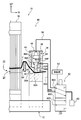
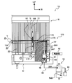
- FIG. 1 is a perspective view showing a state in which the weft tension applying device 30 is mounted on the loom 10 (only a part of which is shown in the drawing).
- the loom 10 includes a sley 12 extending in the left-right direction when viewed from the front.
- the sley 12 is swingable about a left-right axis of the loom 10 (see the arrow A direction), and a groove 12A is formed on the upper surface side along the longitudinal direction.
- the groove portion 12 ⁇ / b> A of the sley 12 the lower end portion of the deformed rod 16 is fastened and fixed by the wedge member 14. That is, the deformation rod 16 is erected and fixed on the sley 12 and can swing with the sley 12.
- the deformed kite 16 includes a plurality of kites 18 whose longitudinal direction is the standing direction, and these kites 18 are arranged side by side in the left-right direction of the loom 10.
- the wing 18 is formed with a concave guide hole 18 ⁇ / b> A that opens to the front side of the loom 10.
- These guide holes 18 ⁇ / b> A form a weft insertion passage 20 that communicates with the loom 10 in the left-right direction.
- the weft insertion passage 20 includes a plurality of sub-nozzles 22 for weft insertion (only one is shown in the drawing) supplied from the main nozzle for weft insertion (not shown) on the left side of the loom 10 when viewed from the front. It is a passage that flies by relay injection action.
- the weft Y is drawn out from a winding portion in a weft storage device (not shown) on the left side of the loom 10 when viewed from the front. Further, the weft Y is injected and supplied and then stopped by a weft locking pin (not shown) on the yarn supply side (left side in FIG. 1), so that the supply amount (the length of the weft Y) at each weft insertion becomes constant. ing.
- a weft detection sensor 24 (weft detector) that is used for detecting the weft Y adjacent to the downstream side in the weft insertion direction of the weft Y in the weft insertion passage 20 of the deformed kite 16 is disposed on the front side of the deformed kite 16. .
- the weft detection sensor 24 is erected and fixed on the front side of the sley 12, and is disposed between the ground warp T1 for forming the woven fabric W1 and the ear thread T2 for forming the discarded ear W2.
- This weft detection sensor 24 has a detection area in the weft insertion path 20 with its detection surface facing the weft insertion path 20 and detects whether or not the weft Y has reached in the weft insertion path 20. ing.
- the weft detection sensor 24 is connected to a control unit 62 (illustrated as a block in the drawing) and outputs a detection result to the control unit 62.
- a weft grasping block 34 of the weft grasping mechanism portion 32 is disposed with a slight gap between the deformation rod 16 and the weft insertion passage 20.
- the weft grip block 34 of the weft grip mechanism 32 is fixed on the sley 12.
- the weft gripping mechanism 32 constitutes a part of the weft tension applying device 30, and an insertion passage 38 through which the tip of the weft Y inserted is inserted is formed in the weft gripping block 34. .
- the insertion passage 38 is formed so as to be surrounded by a wall surface, and the opening area of the inlet portion 38A is equal to or larger than the passage cross-sectional area of the weft insertion passage 20 of the deformed rod 16 (in this embodiment, as an example, about
- the weft introduction passage 40 is set so that the cross-sectional area of the passage gradually decreases (squeezes) from the inlet portion 38A side to a portion (details will be described later) side that grips the tip of the weft Y. Is formed.
- a rectangular weft gripping passage 42 is formed in the insertion passage 38 continuously with the tapered weft introduction passage 40 in the sectional view of FIG. 3.
- the open passage 43 on the downstream side of the weft gripping passage 42 has a taper shape spreading toward the end, and has a shape in which the passage cross-sectional area is gradually enlarged.
- the weft introduction passage 40, the weft gripping passage 42, and the release passage 43 are on an extension line of the weft insertion passage 20 of the deformed kite 16, and they constitute a weft guide passage 25 together with the weft insertion passage 20 of the deformation kite 16. .
- An air cylinder mechanism 44 is disposed above the weft gripping block 34.
- the cylinder 46 of the air cylinder mechanism 44 is hollow inside, and a stopper 48 is press-fitted into the upper opening of the cylinder 46.
- a weft grip pin 50 as a pressing member is disposed inside the cylinder 46.
- the weft gripping pin 50 is configured such that a short cylindrical piston portion 50P is coaxially and integrally provided at one axial end portion (the upper end portion in the present embodiment) of a pin body 50H having a small diameter and a substantially round bar shape.
- the internal space of the cylinder 46 is divided into two chambers by a piston portion 50P.
- the front end 50A side of the pin main body 50H of the weft gripping pin 50 is disposed in the weft gripping passage 42 through a part of the bottom wall portion 46A of the cylinder 46 and the weft gripping block 34.
- a communication hole 52A formed in the shaft core portion of the bottom wall portion 46A and penetrating through the tip 50A side of the pin main body 50H has a larger diameter than the pin main body 50H, and the weft gripping block 34 has a communication hole 52A.
- a communication hole 52B that communicates with the weft holding passage 42 is formed coaxially and with the same diameter as the communication hole 52A.
- the weft gripping pin 50 can grip the front end portion of the weft Y between the inner surface (inner wall surface) of the weft gripping passage 42 (insertion passage 38), and the air cylinder mechanism 44 has the weft gripping pin 50. Is operated to grip the tip of the weft Y.
- the relationship between the passage cross-sectional area Sb of the portion of the insertion passage 38 where the tip of the weft Y is gripped between the weft gripping pin 50 and the passage cross-sectional area Sa of the weft insertion passage 20 of the deformed rod 16 is 0.2 Sa. It is preferable that ⁇ Sb ⁇ 0.7Sa is set. In this embodiment, the passage sectional area Sb of the weft gripping passage 42 is about 30% of the passage sectional area Sa of the weft insertion passage 20.
- FIGS. 4A and 4B show the lower portion of the weft gripping pin 50 and the weft gripping passage 42.
- FIG. As shown in FIGS. 4A and 4B, the width dimension 50W of the distal end portion 50A of the weft gripping pin 50 when viewed in the insertion direction of the insertion passage 38 is the insertion direction of the portion that grips the distal end portion of the weft Y in the insertion passage 38. It is set to be larger than the width dimension (38 W) at the front and rear portions.
- the width dimension 50W of the tip 50A of the weft gripping pin 50 as viewed in the insertion direction of the insertion path 38 is set to be larger than the minimum width dimension 38W of the insertion path 38.
- the weft grip pin 50 is formed with a small-diameter portion 50B having a diameter smaller than that of the tip portion 50A, continuing from the tip portion 50A.
- the weft gripping pin 50 grips the tip of the weft Y between the inner surface (inner wall surface) of the weft gripping passage 42 (insertion passage 38), at least a part of the small diameter portion 50B is inserted into the weft gripping passage 42 (insertion). It is set to be disposed in the passage 38).
- a compression coil spring 54 (“return spring”, in the broad sense “attached” between the bottom wall portion 46A of the cylinder 46 and the piston portion 50P is provided on the outer peripheral side of the weft gripping pin 50. Elements which are grasped as “force members” are wound. One end portion (lower end portion) of the compression coil spring 54 is abutted and locked to the bottom wall portion 46A of the cylinder 46, and the other end portion (upper end portion) is abutted and locked to the end surface (bottom surface) of the piston portion 50P. ing. Therefore, the compression coil spring 54 can press and urge the piston portion 50P in the direction (in FIG.
- the weft gripping pin 50 cannot grip the tip of the weft Y between the inner surface of the weft gripping passage 42 (insertion passage 38) when the piston portion 50P is not pressurized from the upper side ( It is held at a non-gripping position (not shown).
- One end of a tubular air tube 56 is connected to the upper end of the weft holding block 34 to supply air to the upper chamber of the cylinder 46 or to discharge air from the upper chamber of the cylinder 46.
- the other end of the air tube 56 is connected to either the air supply port 58A or the exhaust port 58B of the three-port solenoid valve 58.
- the cylinder 46 can be connected to an air supply source 60 (blocked in the drawing) via an air tube 56 and an air supply port 58A of the three-port solenoid valve 58.
- the 3-port solenoid valve 58 is connected to the control unit 62.
- the control unit 62 performs control so as to switch the port of the three-port solenoid valve 58 connected to the other end of the air tube 56 at a preset setting timing, and controls the three-port solenoid valve 58, whereby the weft yarn
- the direction of raising and lowering of the grip pin 50 can be controlled. Control is performed so that when the leading end of the weft Y reaches the weft gripping passage 42, the weft gripping pin 50 grips the leading end of the weft Y between the inner surface of the weft gripping passage 42 (insertion passage 38).
- the control unit 62 may control to switch the port of the three-port solenoid valve 58 connected to the other end of the air tube 56 at a predetermined timing according to the swing angle of the sley 12. Even if it is controlled to switch the port of the three-port solenoid valve 58 connected to the other end of the air tube 56 at a predetermined timing calculated based on the timing of the weft Y injection supply and the flying speed of the weft Y. Good.
- a tension applying arm 64 as a tension applying member is installed on the front side of the loom 10 with respect to the space between the deformed kite 16 and the weft gripping block 34.
- the tension applying arm 64 has a base end portion 64A fixed to the mounting base 28 by fastening with a screw 29, and is fixed to the loom frame 26 via the mounting base 28, and the deformed kite 16 and the weft gripping mechanism portion 32 from the pre-weaving side. It is extended in the direction toward.
- the loom frame 26 constitutes a stationary portion that is not displaced even when the deformation rod 16 is swung.
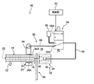
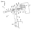
- the tension applying arm 64 is in a state in which the tip of the weft Y is gripped by the weft gripping mechanism portion 32 and between the deformed scissors 16 and the weft gripping mechanism portion 32 when the deformed scissors 16 swing in the strike direction ( Between the downstream end in the weft insertion direction of the deformed kite 16 and the upstream end in the weft inserting direction of the weft gripping mechanism portion 32), a tension is applied to the weft Y by relative displacement with the deformed kite 16 in contact with the weft Y. (See FIG. 2).
- the tension applying arm 64 is formed in a thin plate shape, and the left and right direction of the loom 10 is disposed in the plate thickness direction, the tip end portion 64B is formed in an arc shape, and the upper side portion on the tip end portion 64B side is in the longitudinal direction.
- the guide portion 64C is gently inclined upwardly toward the base end portion 64A. The guide portion 64C comes into contact with the weft Y when the deformation rod 16 swings in the beating direction and guides the contact portion of the weft Y upward with respect to the height position of the weft insertion passage 20 of the deformation rod 16. (See FIGS. 2 and 3). Further, in the present embodiment, the portion of the upper side portion of the tension applying arm 64 that continues to the side opposite to the tip portion 64B side of the guide portion 64C extends substantially horizontally.
- weft Y When weft Y is supplied (injected) from a main nozzle for weft insertion (not shown) on the left side of the loom 10 shown in FIG. 1, a plurality of sub-nozzles 22 for weft insertion (only one is shown in the figure).
- the weft Y travels through the weft insertion passage 20 by the relay injection action.
- the weft detection sensor 24 detects the arrival of the weft Y, and the detection result is output to the control unit 62.
- the front end side of the weft Y is inserted into the insertion passage 38 of the weft gripping block 34 by the injection action (jet flow) of the sub nozzle 22 installed on the downstream side, and passes through the weft introduction passage 40 in the insertion passage 38. Thereafter, at the stage of passing through the weft holding passage 42, the base end side of the weft Y is stopped by a weft locking pin (not shown) on the yarn supply side (left side in FIG. 1), and the leading end of the weft Y stops.
- the port of the 3-port solenoid valve 58 connected to the air tube 56 shown in FIG. 3 is switched from the exhaust port 58B to the air supply port 58A.
- the weft gripping pin 50 is pushed down by this atmospheric pressure.
- the weft grip pin 50 is operated by the air cylinder mechanism 44, whereby the tip of the weft Y is gripped between the tip 50 A of the weft grip pin 50 and the inner surface of the weft grip passage 42.
- the tension applying arm 64 is in contact with the deformed rod 16 and the weft holding mechanism 32.
- the weft Y is supported by the tension applying arm 64, and the contact portion of the weft Y shown in FIG. While being guided upward with respect to the height position of the insertion passage 20, a part of the weft Y is bent into an inverted V shape.
- the weft Y is supported by the tension applying arm 64 and is given a tension by the relative displacement between the tension applying arm 64 and the deformation rod 16.
- the inverted V-shape of the weft Y described above is the upper wall of the weft insertion passage 20 of the deformed rod 16 shown in FIG. 3, the weft gripping position by the weft gripping pin 50, and the tension applying arm 64.
- the upper side portion serves as a fulcrum
- the upper end of the inlet portion 38A of the weft introduction passage 40 also serves as a fulcrum, and tension is applied to the weft Y using these as fulcrums.
- the control of the control unit 62 stops the energization of the three-port solenoid valve 58 so that the weft Y gripping force by the weft gripping pin 50 is loosened, and the air tube 56 is connected at the same time.
- the port of the 3-port solenoid valve 58 is switched from the air supply port 58A to the exhaust port 58B, and high-pressure air is discharged from the exhaust port 58B.
- high-pressure air is consumed only when the weft Y is gripped, and no air is consumed when maintaining the tension of the weft Y.
- the tip of the weft is at the holding position.
- Contrast structure for example, the weft tension applying device according to the above-mentioned Japanese Patent Application Laid-Open No. 10-204751
- a uniform tension state is obtained over the entire length of the weft by the tension applying action on the yarn feeding side and the counter yarn feeding side, so that a high-quality woven fabric can be woven.
- the fulcrum of the tension applying arm 64 when applying tension to the weft Y is the upper side, and the guide part 64C (see FIG. 1) on the upper side of the tension applying arm 64 deforms the contact part of the weft Y. Since the 16 weft insertion passages 20 are guided upward with respect to the height position of the 16 weft insertion passages 20, there is no possibility that the weft Y is detached from the tension applying arm 64 when tension is applied to the weft Y.
- the inserted weft Y is basically removed from the path.
- the weft Y can be stably gripped without coming off.
- the weft Y is guided into the insertion passage 38 using the injection action of the sub nozzle 22, but the opening area of the inlet portion 38A is deformed in the insertion passage 38. Since the cross-sectional area of the sixteen weft insertion passages 20 is set to be about 20% larger, the tip of the weft Y can smoothly enter the insertion passage 38 from the weft insertion passage 20 of the deformed rod 16.
- the insertion passage 38 is formed so that the cross-sectional area of the passage gradually decreases from the inlet portion 38A side toward the portion that grips the front end portion of the weft Y, the front end portion of the weft Y during flight is It is possible to smoothly enter the weft holding passage 42. Further, since the cross-sectional area of the weft gripping passage 42 is about 30% of the cross-sectional area of the weft insertion passage 20, it is possible to suppress the operating stroke of the weft gripping pin 50. As a result, the loom 10 has a high speed. In addition to being able to handle weft insertion, it is also advantageous in terms of durability.
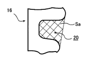
- the passage cross-sectional area Sa (shaded portion) of the weft insertion passage (20) of the deformed kite (16) shown in FIG. 15A and the weft gripping passage (42) of the weft gripping block (34) shown in FIG. 15B.
- a preferable range as a ratio (passage cross-sectional area ratio) to the cross-sectional area Sb (shaded portion) of the above will be described.
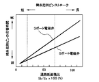
- FIG. 13 shows the cross-sectional area ratio between the weft insertion passage (20) of the deformed kite (16) and the weft gripping passage (42) of the weft gripping block (34) and the response time of the weft gripping pin 50 to this ratio.
- the relationship is shown in a graph.
- the cross-sectional area Sa of the weft insertion passage (20) of the deformed rod (16) is a predetermined value (constant)
- the cross-sectional area Sb of the weft gripping passage (42) of the weft gripping block (34) is The result when variable is shown.
- the response time of the weft gripping pin (50) becomes longer as the passage sectional area ratio increases. This is because the stroke of the weft gripping pin (50) becomes longer as the passage cross-sectional area ratio becomes larger.
- the 3-port solenoid valve (58) that supplies high-pressure air from one side of the weft gripping pin (50) has a slower response time than the 5-port solenoid valve that supplies from both sides of the weft gripping pin (50).
- the air consumption and the solenoid valve driving power can be suppressed, and the initial cost is low. In other words, which of the 3-port solenoid valve (58) and the 5-port solenoid valve is applied is determined according to necessity.
- FIG. 14 shows the ratio of the cross-sectional area of the weft insertion passage (20) of the deformed kite (16) and the weft gripping passage (42) of the weft gripping block (34) and the weft to the weft gripping passage (34).
- the relationship with the ease of entering (Y) is shown in a graph.
- the cross-sectional area Sa of the weft insertion passage (20) of the deformed rod (16) is set to a predetermined value (constant), and the weft gripping of the weft gripping block (34) is performed.
- the results when the passage cross-sectional area Sb of the passage (42) is variable are shown.
- FIG. 14 it can be seen that the weft (Y) is less likely to enter the weft gripping passage (42) as the passage cross-sectional area ratio is smaller in any thickness of the weft (Y).
- the passage cross-sectional area ratio in which the response time of the weft gripping pin (50) is short and the weft (Y) easily enters the weft gripping passage (42) is in the range of 20% to 70%.
- the relationship with the cross-sectional area Sa is preferably set to 0.2Sa ⁇ Sb ⁇ 0.7Sa.
- the weft tension applying device 30 has a width dimension 50W of the distal end portion 50A of the weft gripping pin 50 as viewed in the insertion direction of the insertion path 38. Therefore, the weft Y in the insertion passage 38 can be more reliably gripped regardless of the position in the width direction of the weft Y.
- the weft grip pin 50 is formed with a small diameter portion 50B having a diameter smaller than the tip portion 50A continuously from the tip portion 50A, and the weft grip pin 50 passes the tip portion of the weft Y to the weft grip passage 42 ( 4B because at least a part of the small diameter portion 50B is set to be disposed in the weft gripping passage 42 (insertion passage 38) in the state of being gripped between the inner surface of the insertion passage 38).
- a gap B is formed between the small diameter portion 50B and the weft gripping passage 42 (insertion passage 38). For this reason, even if an air flow to be inserted by wetting of the sub-nozzle 22 (see FIG.
- the tension applying arm 64 is extended from the pre-weaving side in a direction toward the space between the deformed kite 16 and the weft holding mechanism 32, so that when the deformed kite 16 is swung,
- the tip of the weft Y is inserted into the insertion path 38 of the weft gripping mechanism 32 (in other words, before the weft Y comes into contact with the guide portion 64C of the tension applying arm 64 and the tip of the weft Y is the weft
- the jet (airflow) from the sub-nozzle 22 for weft insertion is not blocked (but does not collide) by the tension applying arm 64 separated to the pre-weaving side.
- the weft tension applying device 30 As described above, according to the weft tension applying device 30 according to this embodiment, it is possible to apply an appropriate tension to the weft Y while suppressing air consumption.
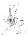
- FIG. 5 is a longitudinal sectional view of the main part of the weft tension applying device 70 according to the present embodiment
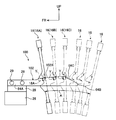
- FIG. 6 shows a tension applying arm 64 as a tension applying member in the weft tension applying device 70.
- 72 are shown in a perspective view.
- the weft tension applying device 70 is provided with two tension applying arms 64 and 72, and the weft tension applying device 30 according to the first embodiment (see FIG. 1 and the like). Is different.
- Other configurations are substantially the same as those of the first embodiment. Therefore, components that are substantially the same as those of the first embodiment are denoted by the same reference numerals and description thereof is omitted.
- FIG. 6 the illustration of parts other than the characteristic part of the present embodiment is partially omitted.
- the tension applying arms 64 and 72 are arranged in parallel along the weft insertion direction of the weft Y at a certain interval. Similar to the tension applying arm 64, the tension applying arm 72 adjacent to the tension applying arm 64 is installed on the front side of the loom 10 with respect to the space between the deformed rod 16 and the weft gripping block 34.
- the tension applying arm 72 has a base end portion 72A fixed to the attachment base 28 with a screw 29 and fixed to the loom frame 26 via the attachment base 28. It extends in the direction toward the part 32.
- the tension applying arm 72 is in a state in which the tip of the weft Y is gripped by the weft gripping mechanism section 32 and between the deformed scissors 16 and the weft gripping mechanism section 32 when the deformed scissors 16 swing in the strike direction ( Between the downstream end in the weft insertion direction of the deformed kite 16 and the upstream end in the weft inserting direction of the weft gripping mechanism portion 32), a tension is applied to the weft Y by relative displacement with the deformed kite 16 in contact with the weft Y. ing.
- the tension applying arm 72 is attached in a state where a member having the same shape as the tension applying arm 64 is turned upside down.
- the distal end portion 72B is formed in an arc shape, and the lower side portion on the distal end portion 72B side is in the longitudinal direction.
- the guide portion 72C is gently inclined downwardly toward the base end portion 72A (with a gentle downward slope).
- the guide portion 72C contacts the weft Y when the deformation rod 16 swings in the strike direction, and guides the contact portion of the weft Y downward with respect to the height position of the weft insertion passage 20 of the deformation rod 16. It has become.
- the lower side portion of the guide portion 72C opposite to the distal end portion 72B side extends substantially horizontally in the present embodiment.
- each of the tension applying arms 64 and 72 is in contact with the weft Y when the deformation rod 16 swings in the beating direction and the contact portion of the weft Y with respect to the height position of the weft insertion passage 20 of the deformation rod 16.
- the guide direction is set upside down with respect to other adjacent tension applying members (72, 64).
- the deformation stroke of the weft Y can be easily lengthened (that is, the weft Y can be easily stretched). This is effective when a stretch yarn having elasticity is used for the weft Y.
- three or more tension applying arms may be arranged in parallel.
- FIG. 7 shows a main part of the weft tension applying device 80 according to the present embodiment in a longitudinal sectional view in front view.
- the weft tension applying device 80 includes a 5-port solenoid valve 82 in place of the 3-port solenoid valve 58, so that the weft tension applying device 30 (FIG. 1, etc.) according to the first embodiment is provided.
- Other configurations are substantially the same as those of the first embodiment. Therefore, components that are substantially the same as those of the first embodiment are denoted by the same reference numerals and description thereof is omitted.
- the opening area of the inlet portion 38A of the insertion passage 38 (weft introduction passage 40) shown in FIG. 7 is set to be 50% larger than the passage cross-sectional area of the weft insertion passage 20 of the deformed kite 16. Further, the cross-sectional area of the weft gripping passage 42 is set to about 50% of the cross-sectional area of the weft introduction passage 40.
- One end of an air tube 56 is connected to the upper end of the weft grip block 34 to supply air to the upper chamber of the cylinder 46 or to discharge air from the upper chamber of the cylinder 46.
- the other end of the tube 56 is connected to either the air supply port 82A or the exhaust port 82C of the 5-port solenoid valve 82.
- one end of a tubular air tube 56A is connected to the side of the weft grip block 34 to supply air to the lower chamber of the inner space of the cylinder 46 or to discharge air from the lower chamber of the inner space of the cylinder 46.
- the other end of the air tube 56A is connected to either the exhaust port 82B or the air supply port 82D of the 5-port solenoid valve 82.
- the cylinder 46 can be connected to the air supply source 60 via the air tube 56 and the air supply port 82A of the 5-port solenoid valve 82, and the air supply port 82D of the air tube 56A and the 5-port solenoid valve 82 is connected to the cylinder 46. Via the air supply source 60.
- the 5-port solenoid valve 82 is connected to the control unit 62.
- the control unit 62 performs control so as to switch the port of the 5-port solenoid valve 82 connected to the other end of the air tubes 56, 56A at a preset setting timing, and controls the 5-port solenoid valve 82.
- the direction of lifting and lowering of the weft gripping pin 84 as a pressing member can be controlled.
- the timing for switching the port of the 5-port solenoid valve 82 is the same as in the first embodiment.
- the weft gripping pin 84 has the same configuration as the weft gripping pin 50 (see FIG. 4A) in the first embodiment except that the small diameter portion 50B (see FIG. 4A) is not formed. That is, the weft gripping pin 84 is configured such that a short cylindrical piston portion 84P is coaxially and integrally provided at one end portion in the axial direction of a pin body 84H having a small diameter and a substantially round bar shape.
- the same components as those of the weft gripping pin 50 (see FIG. 4A) in the first embodiment are denoted by the same reference numerals.
- the compression coil spring 54 (see FIG. 3) in the first embodiment is not disposed inside the cylinder 46.
- substantially the same operation and effect as those of the first embodiment described above can be obtained, and high operation performance can be ensured even if a very thick yarn is used for the weft Y.
- the weft gripping passage of the weft Y The 5-port solenoid valve 82 is used for driving the weft gripping pin 84 although the operation stroke of the weft gripping pin 84 is increased by the amount that the cross-sectional area of the weft gripping passage 42 is large. As a result, the operation of the weft gripping pin 84 becomes faster, so that the response performance when gripping the weft Y is also ensured.
- FIG. 8 is a plan view showing a main part of the weft tension applying device 90 according to this embodiment.
- the weft tension applying device 90 is provided with an weft tension applying device according to the first embodiment in that an air passage portion 92 for ejecting air toward the weft detection sensor 24 is formed. It is different from the device 30 (see FIG. 1 etc.).
- Other configurations are substantially the same as those of the first embodiment. Therefore, components that are substantially the same as those of the first embodiment are denoted by the same reference numerals and description thereof is omitted.
- a jet nozzle 94A of a clean nozzle 94 is provided adjacent to the downstream side in the weft insertion direction of the weft Y in the weft insertion passage 20 of the deformation kite 16, and the jet port 94A is provided on the deformation kite 16A. Is arranged opposite to the detection surface 24A of the weft detection sensor 24.
- the clean nozzle 94 is attached to the back side of the deformed rod 16, and one end of an air tube 96 is connected to the base end side. The other end of the air tube 96 is connected to the exhaust port 58B of the three-port solenoid valve 58. That is, the clean nozzle 94 and the air tube 96 constitute an air passage portion 92 for ejecting the exhaust air supplied to the air cylinder mechanism 44 and used from the ejection port 94A.
- the high-pressure air discharged from the clean nozzle 94 is jetted onto the detection surface 24A of the weft detection sensor 24 through the gaps of the wings 18.
- the clean nozzle 94 By mounting the clean nozzle 94 in this way, the high-pressure air used to drive the weft gripping pin 50 is not discharged into the atmosphere wastefully, and the detection surface 24A of the weft detection sensor 24, which is easily attached to the fluff, is removed every weft insertion. Can be cleaned.
- operations and effects similar to those of the first embodiment described above can be obtained, and stable weft detection can be performed.
- FIG. 9 shows a side view action diagram for explaining the action of the weft tension applying device 100 according to the present embodiment.
- the illustration of the components on the front side in the drawing relative to the tension applying arm 102 as the tension applying member is omitted, and the deformation state of the deformed scissors 16 and a part of the weft is shown by a two-dot chain line. .
- the weft tension applying device 30 according to the first embodiment is that an arcuate portion 102A is formed on the upper side of the tension applying arm 102. ) Is different.
- Other configurations are substantially the same as those of the first embodiment. Note that components that are substantially the same as those of the first embodiment are denoted by the same reference numerals and description thereof is omitted.
- the tension applying arm 102 shown in FIG. 9 extends in a direction from the pre-weaving side to the space between the deformed kite 16 and the weft gripping mechanism portion 32 (see FIG. 1), and an arcuate portion 102A is formed on the upper side portion. Except for the points described above, the configuration is the same as that of the tension applying arm 64 (see FIG. 1) in the first embodiment.
- the arcuate portion 102A of the tension applying arm 102 is provided on the front side of the guide portion 64C, and is provided along the swinging direction of the deformed rod 16 (so as to coincide with the swinging motion trajectory). It is formed in an arc shape.
- the stretch amount of the weft Y is the position between the arcuate portion 102A and the upper wall position of the guide hole 18A.
- the arc-shaped portion 102A is formed in an arc shape along the swinging direction of the deformed rod 16 (refer to the direction of arrow A), so the position of the arc-shaped portion 102A and the top of the guide hole 18A
- the distance L1 from the wall position is constant and the amount of weft Y stretched is constant.
- the sley 12 swings. Even if the deformed wrinkle 16 changes its position (in FIG. 9, any position of reference numerals 16A, 16B, and 16C), the amount of weft Y stretched can be kept constant, so that more stable fabric quality can be obtained. .
- FIG. 10 shows a side view action diagram for explaining the action of the weft tension applying device 110 according to the present embodiment.
- the illustration of the components on the nearer side of the drawing than the tension applying arm 112 as the tension applying member is omitted, and the deformation state of the deformed scissors 16 and a part of the weft Y is shown by a two-dot chain line. Yes.
- the tension applying arm 112 is the tension applying arm 72 in the second embodiment (see FIG. 6) except that an arc-shaped portion 112A is formed on the lower side. ), And is extended in a direction from the pre-weaving side toward the space between the deformed kite 16 and the weft gripping mechanism 32 (see FIG. 1). Therefore, the same components as those of the tension applying arm 72 (see FIG. 6) are denoted by the same reference numerals and description thereof is omitted.
- the other configuration of the weft tension applying device 110 is substantially the same as that of the first embodiment.
- symbol is attached
- the arc-shaped portion 112A of the tension applying arm 112 shown in FIG. 10 is provided on the pre-weaving side continuously to the guide portion 72C, and is along the swing direction of the deformed rod 16 (coincides with the locus of the swing motion). It is formed in an arc shape.
- the amount of stretch of the weft Y is the position of the arcuate portion 112A and the position of the lower wall of the guide hole 18A.
- the arc-shaped portion 112A is formed in an arc shape along the swinging direction of the deformed rod 16 (see the arrow A direction), so that the position of the arc-shaped portion 112A and the bottom of the guide hole 18A
- the distance L2 from the wall position is constant, and the amount of weft Y stretched is constant.
- FIG. 11 shows a main part of the weft tension applying device 120 according to the present embodiment in a longitudinal sectional view in a side view.
- the weft tension applying device 120 is provided with an insertion passage 126 instead of the insertion passage 38, and the air cylinder mechanism 44 is disposed with the axial direction of the weft gripping pin 50 being in the horizontal direction.
- This is different from the weft tension applying device 30 (see FIG. 1 and the like) according to the first embodiment.
- Other configurations are substantially the same as those of the first embodiment. Therefore, components that are substantially the same as those of the first embodiment are denoted by the same reference numerals and description thereof is omitted.
- the illustration of parts other than the characteristic part of the present embodiment is partially omitted.
- an insertion passage 126 is formed through the weft grip block 122, and the insertion passage 126 is formed so that the periphery is surrounded by a wall surface.
- the inlet section 126A is circular and the passage cross-sectional area gradually decreases from the inlet section 126A side toward the portion that grips the tip of the weft Y. It is formed in a constricted tapered shape so as to be (squeezed).
- the weft gripping passage 130 constituting a part of the insertion passage 126 is formed continuously with the weft introduction passage 128, and the inner peripheral surface thereof has a cylindrical inner surface.
- the insertion passage 126 is otherwise configured in the same manner as the insertion passage 38 (see FIG. 3, etc.) (that is, the weft introduction passage 128 has the same configuration as the weft introduction passage 40 (see FIG. 3, etc.)). Is the same configuration as the weft grip passage 42 (see FIG. 3 and the like).
- the air cylinder mechanism 44 is inserted from the back side of the weft gripping block 122, and when the weft gripping pin 50 grips the weft Y between the inner surface of the weft gripping passage 130, the weft gripping pin 50 is It is configured to operate from the anti-weaving front side (right side in the figure) to the weaving front side (left side in the figure).
- the weft holding block 122 has the same configuration as the weft holding block 34 (see FIG. 1) in the first embodiment except for the above points, and is fixed on the sley 12.
- the same operations and effects as those of the first embodiment described above can be obtained. Further, by making the shapes of the weft introduction passage 128 and the weft grasping passage 130 as described above, the manufacturing cost of the weft grasping block 122 can be greatly reduced.
- FIG. 12 The principal part of the weft tension applying apparatus 140 which concerns on this embodiment is shown by the side view by FIG.
- the weft tension applying device 140 is different from the weft tension applying device 30 (see FIG. 1 etc.) according to the first embodiment in that the tension applying arm 64 can be moved by the moving mechanism 142.
- Other configurations are substantially the same as those of the first embodiment. Therefore, components that are substantially the same as those of the first embodiment are denoted by the same reference numerals and description thereof is omitted.
- FIG. 12 the illustration of parts other than the characteristic part of the present embodiment is partially omitted.
- the moving mechanism 142 includes a vertical column portion 144, and a rack 146 extending in the vertical direction of the loom 10 is fixed to the vertical column portion 144, and on both sides of the rack 146.
- a guide rail 148 extending in parallel with the rack 146 is formed. Stoppers 149 are provided at the upper and lower ends of the guide rail 148.
- a pinion 150 that meshes with the rack 146 is rotatably supported on the mounting base 28, and a slider 152 that is slidable (slidable) along the longitudinal direction of the guide rail 148 is fixed.
- the pinion 150 can be driven by a motor (not shown), and the mounting base 28 is raised when the motor is rotated forward, and the mounting base 28 is lowered when the motor is reversed.
- a horizontal column portion 154 that is fixed to the loom frame 26 and extends in the front-rear direction of the loom 10 is provided on the lower end side of the vertical column portion 144.
- a rack 156 is fixed along the longitudinal direction of the horizontal column portion 154, and guide rails 158 extending in parallel with the rack 156 are formed above and below the rack 156. Stoppers 159 are provided at the left and right ends of the guide rail 158.
- a pinion 160 that meshes with the rack 156 is rotatably supported on the lower end portion side of the vertical column portion 144, and a slider 162 that is slidable (slidable) along the longitudinal direction of the guide rail 158. Is fixed.
- the pinion 160 can be driven by a motor (not shown). When the motor rotates forward, the vertical column portion 144 moves to the anti-weaving front side (right side in the drawing) of the loom 10, and when the motor reverses, The column part 144 moves to the weaving front side (left side in the figure) of the loom 10.
- the moving mechanism 142 is configured to move the tension applying arm 64 in the vertical direction and in the horizontal direction perpendicular to the weft insertion direction of the weft Y by driving the motor.
- the tension applying arm 64 extends in a direction from the pre-weaving side to the space between the deformed kite 16 and the weft gripping mechanism portion 32 (see FIG. 1). It is constant.
- the same operations and effects as those of the first embodiment described above can be obtained, and the position of the tension applying arm 64 can be easily set according to the type of weft Y and the weft insertion conditions. can do.
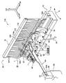
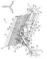
- FIG. 16 is a perspective view of the weft tension applying device 170 according to the present embodiment at the end of weft insertion.
- FIG. 17 is a perspective view of the weft tension applying device 170 in the state of applying tension to the weft Y. It is shown in 18 shows a main portion of the weft tension applying device 170 in a longitudinal sectional view in front view, and FIG. 19 shows a side view of the weft tension applying device 170 cut at the position of the weft gripping passage 178.
- FIG. 20 is a side sectional view showing a state in which the weft tension applying device 170 is cut near the position where the tension applying arm 64 is disposed.
- the weft gripping block 172 is disposed on the front side of the deformed kite 16, and the mounting position in the left-right direction can be changed according to the set weaving width.
- An insertion portion 172A that fits into the guide hole 18A of the deformed rod 16 is provided at the upper end of the weft grip block 172.
- the upstream portion of the insertion portion 172A in the weft insertion direction has an outer shape in a side sectional view that is the same as the shape in a side view of the guide hole 18A. That is, no gap is formed between the portion on the upstream side in the weft insertion direction of the insertion portion 172A and the guide hole 18A to allow the jet flow from the sub nozzle 22 to pass downstream in the weft insertion direction.
- an insertion path 174 is formed at the upper end of the weft grip block 172 including the insertion portion 172A.
- the insertion passage 174 is formed so as to be surrounded by a wall surface, and the tip of the weft Y is inserted through the insertion passage 174.
- the weft introduction passage 176 constituting the upstream side of the insertion passage 174 in the weft insertion direction is formed in a substantially elliptical shape with its inlet portion 174A being long in the substantially front-rear direction of the loom 10 (direction substantially perpendicular to the paper surface of FIG. 18). (See FIG. 19).
- the weft introduction passage 176 gradually contracts from the inlet portion 174A side to the portion side (right side in the drawing) that grips the front end portion of the weft Y from the upper surface side and the back surface side (the back side of the paper surface in FIG. 18). It is formed in a shape that is squeezed (squeezed) (see FIG. 19).
- the weft gripping passage 178 constituting the downstream side in the weft insertion direction of the insertion passage 174 is formed continuously with the weft introduction passage 176 and the inner peripheral surface thereof has a cylindrical inner surface (see FIG. 19).
- a plurality of punch holes 180 are formed in the weft introduction passage 176 and the weft grip passage 178.
- the punching hole 180 passes through the weft introduction passage 176 and the weft gripping passage 178 to the weaving front side of the weft gripping block 172, and is an exhaust passage for guiding the jet flow by the sub nozzle 22 from the insertion passage 174 to the outside of the weft gripping block 172. Is forming. That is, the hole 180 has a function of suppressing the air resistance of the airflow in the insertion passage 174.
- the punch hole 180 is penetrated from the weft introduction passage 176 and the weft grip passage 178 in other directions such as the upper side, the lower side, or the anti-weaving front side (back side) of the weft grip block 172. It may be.
- the total cross-sectional area in the direction perpendicular to the penetration direction in the plurality of punch holes 180 is set to be equal to or greater than the cross-sectional area in the direction perpendicular to the extending direction in the weft holding passage 178.
- the insertion passage 174 is otherwise configured in the same manner as the insertion passage 38 (see FIG. 3 and the like) in the first embodiment (that is, the weft introduction passage 176 has the same configuration as the weft introduction passage 40 (see FIG. 3 and the like)).
- the weft grip passage 178 has the same structure as the weft grip passage 42 (see FIG. 3 and the like).
- the weft gripping block 172 is provided with an air cylinder mechanism 182.
- the air cylinder mechanism 182 is arranged such that the weft grip pin 84 (see FIG. 7) according to the third embodiment is disposed instead of the weft grip pin 50 (see FIG. 3) of the first embodiment. Except for this, the configuration is substantially the same as the air cylinder mechanism 44 (see FIG. 3) of the first embodiment.
- the air cylinder mechanism 182 operates the weft gripping pin 84 obliquely upward toward the anti-weaving front side (right side in the drawing). It has a configuration.
- the weft insertion sub-nozzle 22 is disposed adjacent to the weft gripping block 172 on the upstream side in the weft insertion direction.
- the insertion time of the weft Y into the insertion path 174 can be shortened compared to a configuration in which the sub nozzle 22 is not adjacent to the weft gripping block 172.
- a pin holder 184 is fixed on the wedge member 14 fixed to the sley 12 at a position corresponding to the tension applying arm 64.
- the mounting position of the pin holder 184 in the left-right direction of the loom 10 (direction perpendicular to the paper surface of FIG. 20) is changed together with the tension applying arm 64 according to the set weaving width.
- the pin holder 184 is L-shaped in a side view, and includes a lower wall portion 184A that is fixed to the wedge member 14 and a vertical wall portion 184B that is disposed on the back side of the deformed rod 16.
- a plate-shaped rubber member 190 is attached to the vertical wall portion 184B between the back surface of the deformed rod 16, and an opening 186 into which the portion on the tip end 64B side of the tension applying arm 64 can be inserted is formed. Yes.
- FIG. 21 shows the pin holder 184 in a front view.
- the opening 186 is formed at the center of the vertical wall 184B.
- the split pin 188 is being fixed to the vertical wall part 184B above and below the opening part 186.
- the split pin 188 protrudes to the pre-weaving side with the direction perpendicular to the vertical wall portion 184B as the axial direction (see FIG. 20).
- the split pin 188 is arranged at the upper and lower positions with the guide hole 18A of the deformed scissors 16 in between, and enters between the adjacent scissors 18 to bend the warps 18 laterally ( Elastically deformed).
- the split pin 188 forms a space in which a portion on the tip end portion 64B (see FIG. 20) side of the tension applying arm 64 can be inserted between the wings 18.
- the weft thread Y block corresponding to various weaving width settings can be obtained by changing the mounting positions of the weft grip block 172, the tension applying arm 64, and the pin holder 184 (see FIG. 20) in the left-right direction. Tension can be applied.
- the weft grip pins 50, 84 are short cylindrical piston portions at one end in the axial direction of the pin bodies 50H, 84H having a small diameter and a substantially round bar shape.
- 50P and 84P are coaxially and integrally provided.
- a piston disposed in the internal space of the cylinder of the cylinder mechanism is disposed, and the pressing member is fixed to the shaft core portion of the piston. It may be another pressing member such as a substantially round bar-like or a substantially square bar-like member.
- insertion path 38, 126, 174 is toward the site
- the cross-sectional area of the passage is formed so as to be gradually reduced, and such a configuration is preferable from the viewpoint of responsiveness of the weft gripping pins 50 and 84, but the tip of the weft is gripped from the inlet side of the insertion passage. It is also possible to adopt a configuration in which the cross-sectional area of the passage toward the portion to be fixed is constant.
- the width dimension 50W of the tip 50A of the weft gripping pin 50 as viewed in the insertion direction of the insertion path 38 is set to be larger than the minimum width dimension 38W of the insertion path 38.
- the width dimension of the tip portion of the pressing member is slightly smaller than the minimum width dimension of the insertion path when viewed in the insertion direction of the insertion path. (For example, the gap between the two may be smaller than the radius of the weft).
- the weft gripping pin 50 is formed with a small diameter portion 50B having a diameter smaller than that of the tip portion 50A continuously from the tip portion 50A, so that a reverse flow of the airflow to be inserted is inserted.
- a small diameter portion 50B having a diameter smaller than that of the tip portion 50A continuously from the tip portion 50A, so that a reverse flow of the airflow to be inserted is inserted.
- the tension applying arms 64, 72, 102, and 112 are formed in a thin plate shape and the left and right directions of the loom 10 are disposed in the plate thickness direction.
- the loom 10 is arranged with the left-right direction as the plate thickness direction, and the upper side or the lower side in contact with the weft in the front view of the loom is formed so that the central portion in the plate thickness direction is raised. Good.
- the tension applying arms 64, 72, 102, 112 are extended from the pre-weaving side in a direction toward the space between the deformed kite 16 and the weft gripping mechanism portion 32, and are sub nozzles for weft insertion.
- the tension applying member is, for example, between the deformation rod 16 and the weft holding mechanism 32.
- Other tension applying members such as a tension applying member that is provided and extends in the vertical direction may be used.
Landscapes
- Engineering & Computer Science (AREA)
- Textile Engineering (AREA)
- Looms (AREA)
Abstract
エアの消費量を抑えながら緯糸に適度な張力を付与することができる緯糸張力付与装置を得る。 変形筬(16)の緯入れ通路(20)に対して緯糸(Y)の緯入れ方向下流側には緯糸把持機構部(32)が配置されている。この緯糸把持機構部(32)においては、緯入れされた緯糸(Y)の先端部が挿通路(38)に挿通され、緯糸把持ピン(50)が緯糸(Y)の先端部を挿通路(38)の内面との間に把持可能となっており、エアシリンダ機構(44)が緯糸把持ピン(50)を作動させて緯糸(Y)の先端部を把持させる。これに対して、張力付与アーム(64)は、織機フレーム(26)に固定されており、緯糸把持機構部(32)による緯糸(Y)の先端部の把持状態でかつ変形筬(16)の筬打ち方向への揺動時に変形筬(16)と緯糸把持機構部(32)との間にて緯糸(Y)に接して変形筬(16)との相対変位により緯糸(Y)に張力を付与する。
Description
本発明は、緯入れされた緯糸に張力を付与する緯糸張力付与装置に関する。
緯糸張力付与装置においては、緯糸に適度な張力を付与するために、例えば、緯糸捕捉パイプ内へストレッチノズルからエアを吹き込んで緯糸を捕捉する装置がある(例えば、特開平10-204751号公報参照)。このような装置では、ストレッチノズルの噴射は、緯糸の先端部が緯糸捕捉パイプの開口側の緯糸導入凹部に到達する前に開始され、筬打ち直前に停止している。
しかしながら、この装置では、緯糸の先端部が緯糸導入凹部に到達する前から筬打ち直前まで高圧エアを噴射し続けるため、エアの消費量が増えて消費電力が増加してしまう。
本発明は、上記事実を考慮して、エアの消費量を抑えながら緯糸に適度な張力を付与することができる緯糸張力付与装置を得ることが目的である。
本発明の第1の態様に係る緯糸張力付与装置は、変形筬の緯入れ通路に対して緯糸の緯入れ方向下流側に配置されてスレー上に固定され、周囲が壁面によって囲まれて形成されると共に緯入れされた前記緯糸の先端部が挿通される挿通路と、前記緯糸の先端部を前記挿通路の内面との間に把持可能な押付部材と、前記押付部材を作動させて前記緯糸の先端部を把持させるエアシリンダ機構と、を備えた緯糸把持機構部と、織機フレームに固定され、前記緯糸把持機構部による前記緯糸の先端部の把持状態でかつ前記変形筬の筬打ち方向への揺動時に前記変形筬と前記緯糸把持機構部との間にて前記緯糸に接して前記変形筬との相対変位により前記緯糸に張力を付与する張力付与部材と、を有する。
本発明の第1の態様に係る緯糸張力付与装置によれば、変形筬の緯入れ通路に対して緯糸の緯入れ方向下流側には緯糸把持機構部が配置されてスレー上に固定されている。この緯糸把持機構部においては、周囲が壁面によって囲まれた挿通路が形成されると共に、緯入れされた緯糸の先端部が挿通路に挿通され、押付部材が緯糸の先端部を挿通路の内面との間に把持可能となっており、エアシリンダ機構が押付部材を作動させて緯糸の先端部を把持させる。これに対して、張力付与部材は、織機フレームに固定されており、緯糸把持機構部による緯糸の先端部の把持状態でかつ変形筬の筬打ち方向への揺動時に変形筬と緯糸把持機構部との間にて緯糸に接して変形筬との相対変位により緯糸に張力を付与する。このため、エアは緯糸を把持する際にだけ消費される。
本発明の第2の態様は、第1の態様に係る緯糸張力付与装置において、前記挿通路は、入口部の開口面積が前記変形筬の緯入れ通路の通路断面積に対して同等以上に設定されると共に、前記入口部側から前記緯糸の先端部を把持する部位側へ向けて通路断面積が徐々に小さくなるように形成されている。
本発明の第2の態様に係る緯糸張力付与装置によれば、挿通路は入口部の開口面積が変形筬の緯入れ通路の通路断面積に対して同等以上に設定されるので、緯糸の先端部は変形筬の緯入れ通路から挿通路内へスムーズに入ることができる。また、挿通路は入口部側から緯糸の先端部を把持する部位側へ向けて通路断面積が徐々に小さくなるように形成されているので、緯糸の先端部は挿通路内において把持される位置方向へスムーズに入り込むと共に、押付部材の作動ストロークを抑えることも可能となる。
本発明の第3の態様は、第1の態様又は第2の態様に係る緯糸張力付与装置において、前記張力付与部材は、織り前側から前記変形筬と前記緯糸把持機構部との間へ向かう方向に延出され、前記変形筬の筬打ち方向への揺動時に前記緯糸に接して当該緯糸における接触部を前記変形筬の緯入れ通路の高さ位置に対して上下方向に案内する案内部を備えている。
本発明の第3の態様に係る緯糸張力付与装置によれば、張力付与部材の案内部は、変形筬の筬打ち方向への揺動時に緯糸に接して当該緯糸における接触部を変形筬の緯入れ通路の高さ位置に対して上下方向に案内する。これによって、緯糸が引き伸ばされ、緯糸に張力が付与される。ここで、張力付与部材は、織り前側から変形筬と緯糸把持機構部との間へ向かう方向に延出されているので、変形筬の揺動時で緯糸の先端部が緯糸把持機構部の挿通路に挿入される際(換言すれば、緯糸が張力付与部材の案内部に接する前であってかつ緯糸の先端部が緯糸把持機構部によって把持される前)には、緯入れのための気流は、その織り前側に離れた張力付与部材には阻止されず(衝突せず)に緯糸把持機構部の挿通路内に入り込む。このため、緯糸への張力付与用として張力付与部材が配置されていても、スムーズな緯入れができる。
本発明の第4の態様は、第3の態様に係る緯糸張力付与装置において、前記張力付与部材は、前記案内部に連続してその織り前側に設けられてかつ前記変形筬の揺動方向に沿って円弧状に形成された円弧状部を備えている。
本発明の第4の態様に係る緯糸張力付与装置によれば、張力付与部材の円弧状部は、案内部に連続してその織り前側に設けられてかつ変形筬の揺動方向に沿って円弧状に形成されているので、緯糸が円弧状部に接した状態では、変形筬が揺動により位置を変えても緯糸の引き伸ばし量が一定に保たれる。
本発明の第5の態様は、第1の態様~第4の態様のいずれか1態様に係る緯糸張力付与装置において、前記挿通路の挿通方向に見て前記押付部材の先端部の幅寸法は前記挿通路の最小幅寸法よりも大きく設定されている。
本発明の第5の態様に係る緯糸張力付与装置によれば、挿通路の挿通方向に見て押付部材の先端部の幅寸法は挿通路の最小幅寸法よりも大きく設定されているので、挿通路内の緯糸をより確実に把持することができる。
本発明の第6の態様は、第1の態様~第5の態様のいずれか1態様に係る緯糸張力付与装置において、前記押付部材には、その先端部に連続して前記先端部よりも径が小さい小径部が形成されると共に、前記押付部材が前記緯糸の先端部を前記挿通路の内面との間に把持した状態では前記小径部の少なくとも一部が前記挿通路内に配設されるように設定されている。
本発明の第6の態様に係る緯糸張力付与装置によれば、押付部材の小径部は、押付部材の先端部に連続して前記先端部よりも径が小さく設定されており、押付部材が緯糸の先端部を挿通路の内面との間に把持した状態では、押付部材の小径部の少なくとも一部が挿通路内に配設されるので、緯糸の把持状態では、小径部と挿通路との間に隙間が形成される。このため、緯糸の把持状態で緯入れさせる気流が挿通路内に入っても逆流の発生を抑えることができ、緯糸の把持性能が一層安定化する。
本発明の第7の態様は、第1の態様~第6の態様のいずれか1態様に係る緯糸張力付与装置において、前記張力付与部材が前記緯糸の緯入れ方向に沿って複数並設され、各張力付与部材は、前記変形筬の筬打ち方向への揺動時に前記緯糸に接して当該緯糸における接触部を前記変形筬の緯入れ通路の高さ位置に対して上下方向に案内すると共に、隣り合う他の張力付与部材とは案内方向が上下逆に設定されている。
本発明の第7の態様に係る緯糸張力付与装置によれば、張力付与部材が緯糸の緯入れ方向に沿って複数並設されており、各張力付与部材は、変形筬の筬打ち方向への揺動時に緯糸に接して当該緯糸における接触部を変形筬の緯入れ通路の高さ位置に対して上下方向に案内すると共に、隣り合う他の張力付与部材とは案内方向が上下逆に設定されているので、緯糸の引き伸ばし量を容易に大きく設定することができる。
本発明の第8の態様は、第1の態様~第7の態様のいずれか1態様に係る緯糸張力付与装置において、前記変形筬の緯入れ通路における前記緯糸の緯入れ方向下流側に隣接して噴出口が設けられかつ前記噴出口が前記緯糸の検出用とされた緯糸検出センサの検出面に対向配置されると共に、前記エアシリンダ機構へ供給されて使用された排気用のエアを前記噴出口から噴出させるためのエア通路部が形成されている。
本発明の第8の態様に係る緯糸張力付与装置によれば、変形筬の緯入れ通路における緯糸の緯入れ方向下流側に隣接して噴出口が設けられかつその噴出口が緯糸の検出用とされた緯糸検出センサの検出面に対向配置されており、エアシリンダ機構へ供給されて使用された排気用のエアがエア通路部を通って噴出口から緯糸検出センサへ向けて噴出される。このため、緯糸検出センサがクリーニングされ、緯糸検出センサの信頼性が確保される。
本発明の第9の態様は、第1の態様~第8の態様のいずれか1態様に係る緯糸張力付与装置において、前記張力付与部材をモータ駆動によって上下方向、及び前記緯糸の緯入れ方向に直交してかつ水平な方向に移動させる移動機構が前記織機フレームに設けられている。
本発明の第9の態様に係る緯糸張力付与装置によれば、張力付与部材をモータ駆動によって上下方向、及び緯糸の緯入れ方向に直交してかつ水平な方向に移動させる移動機構が織機フレームに設けられているので、緯糸の種類や緯入れ条件に応じた張力付与部材の位置設定が容易になる。
本発明の第10の態様は、第1の態様~第9の態様のいずれか1態様に係る緯糸張力付与装置において、前記挿通路において前記緯糸の先端部が前記押付部材との間に把持される部位の通路断面積Sbと前記変形筬の緯入れ通路の通路断面積Saとの関係が、0.2Sa≦Sb≦0.7Saに設定されている。
本発明の第10の態様に係る緯糸張力付与装置によれば、挿通路において緯糸の先端部が押付部材との間に把持される部位の通路断面積Sbと変形筬の緯入れ通路の通路断面積Saとの関係が、0.2Sa≦Sb≦0.7Saに設定されているので、緯糸が挿通路内の把持位置方向へ挿入される際の入りやすさが確保されつつ、押圧部材のストロークが短いことで応答性が良好となる。
以上説明したように、本発明に係る緯糸張力付与装置によれば、エアの消費量を抑えながら緯糸に適度な張力を付与することができるという優れた効果を有する。
[第1実施形態]
本発明の第1の実施形態に係る緯糸張力付与装置について図1~図4Bを用いて説明する。なお、これらの図において適宜示される矢印FRは織機の織り前側を示しており、矢印UPは織機の上方側を示しており、矢印INは緯糸の緯入れ方向を示している。
本発明の第1の実施形態に係る緯糸張力付与装置について図1~図4Bを用いて説明する。なお、これらの図において適宜示される矢印FRは織機の織り前側を示しており、矢印UPは織機の上方側を示しており、矢印INは緯糸の緯入れ方向を示している。
図1には、緯糸張力付与装置30が織機10(図中では一部のみを図示)に搭載された状態の斜視図が示されている。図1に示されるように、織機10は、正面視で左右方向に延在するスレー12を備えている。スレー12は、織機10の左右方向の軸周りに揺動可能(矢印A方向参照)とされており、その上面側には溝部12Aが長手方向に沿って形成されている。スレー12の溝部12A内には、変形筬16の下端部が楔部材14によって締め付けられて固定されている。すなわち、変形筬16は、スレー12上に立設固定されており、スレー12と共に揺動可能となっている。
また、変形筬16は、その立設方向を長手方向とする多数枚の筬羽18を備えており、これらの筬羽18は、織機10の左右方向に並設されている。筬羽18には、織機10の織り前側に開口する凹状のガイド孔18Aが形成されている。これらのガイド孔18Aは、織機10の左右方向に通じる緯入れ通路20を形成している。緯入れ通路20は、織機10の正面視左側の図示しない緯入れ用メインノズルから噴射供給(射出)された緯糸Yが複数の緯入れ用のサブノズル22(図中では1つのみを示す)のリレー噴射作用によって飛走する通路となっている。
なお、緯糸Yは、織機10の正面視左側の図示しない緯糸貯留装置内の巻付部から引き出されたものである。また、緯糸Yは、噴射供給された後に給糸側(図1では左側)で図示しない緯糸係止ピンによって止められることで各緯入れ時の供給量(緯糸Yの長さ)が一定となっている。
変形筬16の緯入れ通路20における緯糸Yの緯入れ方向下流側に隣接して緯糸Yの検出用とされた緯糸検出センサ24(緯糸検出器)が変形筬16の正面側に配置されている。緯糸検出センサ24は、スレー12の前面側に立設固定され、織布W1を形成するための地経糸T1と捨て耳W2を形成するための耳糸T2との間に配置されている。この緯糸検出センサ24は、緯入れ通路20側に検出面を向けて緯入れ通路20内に検出領域を有しており、緯入れ通路20内における緯糸Yの到達の有無を検出するようになっている。緯糸検出センサ24は、制御部62(図中ではブロック化して図示)に接続されており、検出結果を制御部62に出力するようになっている。
変形筬16の緯入れ通路20に対して緯糸Yの緯入れ方向下流側には、変形筬16との間に若干の間隔を置いて緯糸把持機構部32の緯糸把持ブロック34が配置されている。緯糸把持機構部32の緯糸把持ブロック34は、スレー12上に固定されている。緯糸把持機構部32は、緯糸張力付与装置30の一部を構成しており、緯糸把持ブロック34には、緯入れされた緯糸Yの先端部が挿通される挿通路38が貫通形成されている。
挿通路38は、周囲が壁面によって囲まれて形成されており、入口部38Aの開口面積が変形筬16の緯入れ通路20の通路断面積に対して同等以上に(本実施形態では一例として約20%大きく)設定されると共に、入口部38A側から緯糸Yの先端部を把持する部位(詳細後述)側へ向けて通路断面積が徐々に小さくなる(絞られる)ように緯糸導入通路40が形成されている。また、図3に示されるように、挿通路38には、テーパ状の緯糸導入通路40に連続して図3の断面視で矩形状の緯糸把持通路42が形成されている。
また、緯糸把持通路42の下流側の開放通路43は末広がりのテーパ状となっており、徐々にその通路断面積を拡大させた形状となっている。緯糸導入通路40、緯糸把持通路42、開放通路43は、変形筬16の緯入れ通路20の延長線上にあり、これらは、変形筬16の緯入れ通路20と共に緯糸案内通路25を構成している。
緯糸把持ブロック34の上部には、エアシリンダ機構44が配置されている。エアシリンダ機構44のシリンダ46は内部中空とされており、シリンダ46の上部開口部には、ストッパ48が圧入されている。また、シリンダ46の内部には押付部材としての緯糸把持ピン50が配置されている。
緯糸把持ピン50は、小径で略丸棒状のピン本体50Hの軸線方向一端部(本実施形態では上端部)に短円柱状のピストン部50Pが同軸的かつ一体に設けられて構成されている。シリンダ46の内部空間はピストン部50Pにより二室に隔成されている。緯糸把持ピン50におけるピン本体50Hの先端部50A側はシリンダ46の底壁部46A及び緯糸把持ブロック34の一部を貫通して緯糸把持通路42内に配置されている。そして、底壁部46Aの軸芯部に形成されてピン本体50Hの先端部50A側が貫通する連通孔52Aは、ピン本体50Hよりも大径とされると共に、緯糸把持ブロック34には連通孔52Aと緯糸把持通路42とを連通させる連通孔52Bが連通孔52Aと同軸かつ同径で形成されている。これにより、エアによる加圧作用状態では緯糸把持ピン50の軸方向移動(本実施形態では緯糸把持通路42と直交する上下方向の移動)が可能な構成になっている。すなわち、緯糸把持ピン50は、緯糸Yの先端部を緯糸把持通路42(挿通路38)の内面(内壁面)との間に把持可能となっており、エアシリンダ機構44は、緯糸把持ピン50を作動させて緯糸Yの先端部を把持させるようになっている。
また、挿通路38において緯糸Yの先端部を緯糸把持ピン50との間に把持する部位の通路断面積Sbと変形筬16の緯入れ通路20の通路断面積Saとの関係は、0.2Sa≦Sb≦0.7Saに設定されているのが好ましい。本実施形態では、緯糸把持通路42の通路断面積Sbは緯入れ通路20の通路断面積Saの約30%となっている。
図4A及び図4Bには、緯糸把持ピン50の下部及び緯糸把持通路42が示されている。図4A及び図4Bに示されるように、挿通路38の挿通方向に見て緯糸把持ピン50の先端部50Aの幅寸法50Wは、挿通路38において緯糸Yの先端部を把持する部位の挿通方向の前後の部位における幅寸法(38W)よりも、大きく設定されている。換言すれば、挿通路38の挿通方向に見て緯糸把持ピン50の先端部50Aの幅寸法50Wは挿通路38の最小幅寸法38Wよりも大きく設定されている。
また、緯糸把持ピン50には、その先端部50Aに連続して先端部50Aよりも径が小さい小径部50Bが形成されている。そして、緯糸把持ピン50が緯糸Yの先端部を緯糸把持通路42(挿通路38)の内面(内壁面)との間に把持した状態では小径部50Bの少なくとも一部が緯糸把持通路42(挿通路38)内に配設されるように設定されている。
さらに、図3に示されるように、シリンダ46の底壁部46Aとピストン部50Pとの間には、緯糸把持ピン50の外周側に圧縮コイルスプリング54(「リターンスプリング」、広義には「付勢部材」として把握される要素)が巻装されている。圧縮コイルスプリング54の一端部(下端部)はシリンダ46の底壁部46Aに当接係止されており、他端部(上端部)はピストン部50Pの端面(底面)に当接係止されている。従って、圧縮コイルスプリング54は、ピストン部50Pを常時底壁部46Aから離間する方向(図3では上方向)へ押圧付勢してストッパ48のストッパ面48Aに押し当て可能となっている。これにより、緯糸把持ピン50は、ピストン部50Pに上方側からの加圧がなされていないときには、緯糸Yの先端部を緯糸把持通路42(挿通路38)の内面との間に把持できない位置(図示しない非把持位置)に保持されるようになっている。
緯糸把持ブロック34の上端には、シリンダ46の内部空間の上室に空気を供給又はシリンダ46の内部空間の上室の空気を排出するための管状のエアチューブ56の一端部が接続されており、エアチューブ56の他端部は3ポート電磁弁58の空気供給ポート58Aと排気ポート58Bとのいずれかに接続されている。そして、シリンダ46は、エアチューブ56及び3ポート電磁弁58の空気供給ポート58Aを介してエア供給源60(図中ではブロック化して図示)と接続可能となっている。また、3ポート電磁弁58は、制御部62に接続されている。制御部62は、予め設定された設定タイミングにおいて、エアチューブ56の他端部と接続される3ポート電磁弁58のポートを切り替えるように制御し、3ポート電磁弁58を制御することで、緯糸把持ピン50の昇降を方向制御できるようになっている。そして、緯糸Yの先端部が緯糸把持通路42に到達したときに緯糸把持ピン50が緯糸Yの先端部を緯糸把持通路42(挿通路38)の内面との間に把持するように制御がなされる。
なお、制御部62は、スレー12の揺動角度に応じた所定のタイミングで、エアチューブ56の他端部と接続される3ポート電磁弁58のポートを切り替えるように制御してもよいし、緯糸Yの噴射供給のタイミングと緯糸Yの飛走速度に基づいて算出した所定のタイミングで、エアチューブ56の他端部と接続される3ポート電磁弁58のポートを切り替えるように制御してもよい。
一方、図1に示されるように、変形筬16と緯糸把持ブロック34との間に対して織機10の織り前側には、張力付与部材としての張力付与アーム64が設置されている。張力付与アーム64は、基端部64Aが取付ベース28にネジ29による締結で固定され、取付ベース28を介して織機フレーム26に固定されており、織り前側から変形筬16と緯糸把持機構部32との間へ向かう方向に延出されている。織機フレーム26は、変形筬16の揺動時においても変位しない静止部分を構成している。これによって、張力付与アーム64は、緯糸把持機構部32による緯糸Yの先端部の把持状態でかつ変形筬16の筬打ち方向への揺動時に変形筬16と緯糸把持機構部32との間(変形筬16の緯入れ方向下流端と緯糸把持機構部32の緯入れ方向上流端との間)にて緯糸Yに接して変形筬16との相対変位により緯糸Yに張力を付与するようになっている(図2参照)。
また、張力付与アーム64は、薄板状とされて織機10の左右方向を板厚方向として配置されており、先端部64Bが円弧状とされると共に、先端部64B側の上辺部が長手方向の基端部64A側へ向けて上方側に緩やかに傾斜した(緩い上り勾配の)案内部64Cとされている。案内部64Cは、変形筬16の筬打ち方向への揺動時に緯糸Yに接して緯糸Yにおける接触部を変形筬16の緯入れ通路20の高さ位置に対して上方向に案内するようになっている(図2及び図3参照)。また、張力付与アーム64の上辺部において案内部64Cの先端部64B側とは反対側に連続する部位は、本実施形態では、略水平に延在している。
(作用・効果)
次に、上記実施形態の作用及び効果について説明する。
次に、上記実施形態の作用及び効果について説明する。
図1に示される織機10の正面視左側の図示しない緯入れ用メインノズルから緯糸Yが噴射供給(射出)されると、複数の緯入れ用のサブノズル22(図中では1つのみを示す)のリレー噴射作用によって緯糸Yは緯入れ通路20を飛走する。緯糸Yの先端部が織物端側の所定位置に達すると、緯糸検出センサ24によって緯糸Yの到達が検出され、その検出結果が制御部62に出力される。緯糸Yの先端部側は、下流側に設置されたサブノズル22の噴射作用(噴流)によって緯糸把持ブロック34の挿通路38に挿通され、挿通路38における緯糸導入通路40を通過する。その後、緯糸把持通路42を通った段階で織物の給糸側(図1では左側)で緯糸Yの基端部側が図示しない緯糸係止ピンで止められることで緯糸Yの先端部が停止する。
その後、予め設定された設定タイミングにおいて、図3に示されるエアチューブ56に接続される3ポート電磁弁58のポートが排気ポート58Bから空気供給ポート58Aに切り替えられ、高圧エアがエアシリンダ機構44のシリンダ46内に供給されると、この気圧により緯糸把持ピン50が押し下げられる。そして、緯糸把持ピン50がエアシリンダ機構44により作動することで、緯糸Yの先端部が緯糸把持ピン50の先端部50Aと緯糸把持通路42の内面との間に把持される。
この把持状態で変形筬16の筬打ち方向への揺動時には、図1に示される変形筬16及び緯糸把持ブロック34がスレー12の揺動運動によって織り前側へ移動し、緯糸Yの一部が変形筬16と緯糸把持機構部32との間で張力付与アーム64に接する。そして、さらに変形筬16等が織り前側へ移動すると、緯糸Yは張力付与アーム64に支持され、張力付与アーム64の案内部64Cによって図2に示される緯糸Yにおける接触部が変形筬16の緯入れ通路20の高さ位置に対して上方向に案内されながら、緯糸Yの一部が屈曲して逆V字形状となる。つまり、緯糸Yは張力付与アーム64に支持されると共に張力付与アーム64と変形筬16との相対変位により張力が付与される。
その後、クランク角度300°近傍で、織物の反給糸側では緯糸Yに所定の張力が付与されると共に、織物端にある耳糸T2が口閉じされる。なお、前述した緯糸Yの逆V字形状は、初期段階では、図3に示される変形筬16の緯入れ通路20の上壁と、緯糸把持ピン50による緯糸把持位置と、張力付与アーム64の上辺部とが支点となっており、その後は、緯糸導入通路40の入口部38Aの上端も支点となっており、これらを支点として緯糸Yに張力が付与される。
その後、緯糸Yを筬打ちした後に、緯糸把持ピン50による緯糸Yの把持力が緩むように、制御部62の制御により、3ポート電磁弁58への通電を止め、同時にエアチューブ56に接続される3ポート電磁弁58のポートを空気供給ポート58Aから排気ポート58Bからに切り替え、排気ポート58Bから高圧エアを排出する。
以上のように本実施形態では、緯糸Yを把持する際にだけ高圧エアを消費し、緯糸Yの張力を維持する際には全くエアを消費しないので、例えば、緯糸の先端部が保持位置に到達する前から筬打ち直前まで高圧エアを噴射し続けるような対比構造(例えば、前掲の特開平10-204751号公報に係る緯糸張力付与装置)に比べて大幅なエアの消費量の低減が可能になる。また、給糸側と反給糸側の張力付与作用によって緯糸全長にわたって均一な張力状態が得られるので、品質の高い織物を製織できる。
また、緯糸Yに張力を付与する際の張力付与アーム64の支点が上辺部とされると共に、張力付与アーム64の上辺部の案内部64C(図1参照)が緯糸Yにおける接触部を変形筬16の緯入れ通路20の高さ位置に対して上方向に案内するので、緯糸Yに張力を付与する際に緯糸Yが張力付与アーム64から外れる恐れもない。
また、緯糸把持ブロック34の挿通路38(緯糸導入通路40、緯糸把持通路42、及び開放通路43)は、周囲が壁面によって囲まれているため、挿入された緯糸Yは基本的には通路から抜けることがなく、安定した緯糸Yの把持が可能となる。
また、本実施形態に係る緯糸張力付与装置30では、サブノズル22の噴射作用を利用して緯糸Yを挿通路38内に誘導しているが、挿通路38は入口部38Aの開口面積が変形筬16の緯入れ通路20の通路断面積に対して約20%大きく設定されるので、緯糸Yの先端部は変形筬16の緯入れ通路20から挿通路38内へスムーズに入ることができる。また、挿通路38は入口部38A側から緯糸Yの先端部を把持する部位側へ向けて通路断面積が徐々に小さくなるように形成されているので、飛走中の緯糸Yの先端部は緯糸把持通路42内へスムーズに入り込むことができる。さらに、緯糸把持通路42の通路断面積は緯入れ通路20の通路断面積の約30%となっているので、緯糸把持ピン50の作動ストロークを抑えることも可能となり、結果として、織機10の高速緯入れにも対応可能となるうえ、耐久性の面でも有利になっている。
ここで、図15Aに示される変形筬(16)の緯入れ通路(20)の通路断面積Sa(網掛け部分)と、図15Bに示される緯糸把持ブロック(34)の緯糸把持通路(42)の通路断面積Sb(網掛け部分)との比(通路断面積比)として好ましい範囲について説明する。
図13には、変形筬(16)の緯入れ通路(20)と緯糸把持ブロック(34)の緯糸把持通路(42)との通路断面積比と、これに対する緯糸把持ピン50の応答時間との関係がグラフにて示されている。なお、このグラフは、変形筬(16)の緯入れ通路(20)の通路断面積Saを所定値(一定)とし、緯糸把持ブロック(34)の緯糸把持通路(42)の通路断面積Sbを可変とした場合の結果を示している。
図13にも示されるように、通路断面積比が大きくなるほど緯糸把持ピン(50)の応答時間は長くなる。これは通路断面積比が大きくなるほど緯糸把持ピン(50)のストロークも長くなるためである。なお、高圧エアを緯糸把持ピン(50)の片側から供給する3ポート電磁弁(58)は、緯糸把持ピン(50)の両側から供給する5ポート電磁弁に比べて、応答時間が遅くなるが、エア消費量、及び電磁弁駆動電力が抑えられ、イニシャルコストも低いという有利な面がある。換言すれば、3ポート電磁弁(58)と5ポート電磁弁とのいずれを適用するかは、必要性に応じて決められることになる。
図14には、変形筬(16)の緯入れ通路(20)と緯糸把持ブロック(34)の緯糸把持通路(42)との通路断面積比と、これに対する緯糸把持通路(34)への緯糸(Y)の入りやすさとの関係がグラフにて示されている。なお、このグラフも、図13のグラフの場合と同様に、変形筬(16)の緯入れ通路(20)の通路断面積Saを所定値(一定)とし、緯糸把持ブロック(34)の緯糸把持通路(42)の通路断面積Sbを可変とした場合の結果を示している。図14にも示されるように、いずれの太さの緯糸(Y)でも通路断面積比が小さいほど緯糸(Y)は緯糸把持通路(42)に入りにくくなることが分かる。
図13及び図14により、緯糸把持ピン(50)の応答時間が短く、かつ、緯糸把持通路(42)へ緯糸(Y)が入りやすい通路断面積比は、20%~70%の範囲であることが分かる。すなわち、挿通路(38)において緯糸(Y)の先端部が緯糸把持ピン(50)との間に把持される部位の通路断面積Sbと変形筬(16)の緯入れ通路(20)の通路断面積Saとの関係が、0.2Sa≦Sb≦0.7Saに設定されているのが好ましい。
また、本実施形態に係る緯糸張力付与装置30は、図4A及び図4Bに示されるように、挿通路38の挿通方向に見て緯糸把持ピン50の先端部50Aの幅寸法50Wは挿通路38の最小幅寸法38Wよりも大きく設定されているので、緯糸Yがどの幅方向位置に通されても挿通路38内の緯糸Yをより確実に把持することができる。
また、緯糸把持ピン50には、その先端部50Aに連続して先端部50Aよりも径が小さい小径部50Bが形成されると共に、緯糸把持ピン50が緯糸Yの先端部を緯糸把持通路42(挿通路38)の内面との間に把持した状態では小径部50Bの少なくとも一部が緯糸把持通路42(挿通路38)内に配設されるように設定されているので、図4Bに示されるように、緯糸Yの把持状態では、小径部50Bと緯糸把持通路42(挿通路38)との間に隙間Bが形成される。このため、緯糸Yの把持状態でサブノズル22(図1参照)の噴射により緯入れさせる気流が挿通路38内に入っても、前記気流は隙間Bを通り抜ける。つまり、前記気流が緯糸把持ピン50に阻止されることに起因した逆流の発生を抑えることができ、緯糸Yの把持性能が一層安定化する。
また、図1に示されるように、張力付与アーム64は、織り前側から変形筬16と緯糸把持機構部32との間へ向かう方向に延出されているので、変形筬16の揺動時で緯糸Yの先端部が緯糸把持機構部32の挿通路38に挿入される際(換言すれば、緯糸Yが張力付与アーム64の案内部64Cに接する前であってかつ緯糸Yの先端部が緯糸把持機構部32によって把持される前)には、緯入れのためのサブノズル22からの噴流(気流)は、その織り前側に離れた張力付与アーム64には阻止されず(衝突せず)に緯糸把持機構部32の挿通路38内に入り込む。このため、緯糸Yへの張力付与用として張力付与アーム64が配置されていても、スムーズな緯入れができる。なお、張力付与アーム64は、一本の薄板で構成されているため、イニシャルコストも低く抑えることができる。
以上説明したように、本実施形態に係る緯糸張力付与装置30によれば、エアの消費量を抑えながら緯糸Yに適度な張力を付与することができる。
[第2実施形態]
次に、本発明の第2の実施形態に係る緯糸張力付与装置について、図5及び図6を用いて説明する。図5には、本実施形態に係る緯糸張力付与装置70の要部が正面視の縦断面図にて示され、図6には、緯糸張力付与装置70における張力付与部材としての張力付与アーム64、72の設置状態が斜視図にて示されている。これらの図に示されるように、緯糸張力付与装置70は、張力付与アーム64、72が二本設置されている点で、第1の実施形態に係る緯糸張力付与装置30(図1等参照)とは異なる。他の構成は、第1の実施形態とほぼ同様の構成となっている。よって、第1の実施形態と実質的に同様の構成部については、同一符号を付して説明を省略する。また、図6では、本実施形態の特徴部分以外の部分の図示を一部省略している。
次に、本発明の第2の実施形態に係る緯糸張力付与装置について、図5及び図6を用いて説明する。図5には、本実施形態に係る緯糸張力付与装置70の要部が正面視の縦断面図にて示され、図6には、緯糸張力付与装置70における張力付与部材としての張力付与アーム64、72の設置状態が斜視図にて示されている。これらの図に示されるように、緯糸張力付与装置70は、張力付与アーム64、72が二本設置されている点で、第1の実施形態に係る緯糸張力付与装置30(図1等参照)とは異なる。他の構成は、第1の実施形態とほぼ同様の構成となっている。よって、第1の実施形態と実質的に同様の構成部については、同一符号を付して説明を省略する。また、図6では、本実施形態の特徴部分以外の部分の図示を一部省略している。
図5及び図6に示されるように、張力付与アーム64、72は緯糸Yの緯入れ方向に沿って一定の間隔をおいて並設されている。張力付与アーム64に隣り合う張力付与アーム72は、張力付与アーム64と同様に、変形筬16と緯糸把持ブロック34との間に対して織機10の織り前側に設置されている。また、張力付与アーム72は、基端部72Aが取付ベース28にネジ29による締結で固定され、取付ベース28を介して織機フレーム26に固定されており、織り前側から変形筬16と緯糸把持機構部32との間へ向かう方向に延出されている。これによって、張力付与アーム72は、緯糸把持機構部32による緯糸Yの先端部の把持状態でかつ変形筬16の筬打ち方向への揺動時に変形筬16と緯糸把持機構部32との間(変形筬16の緯入れ方向下流端と緯糸把持機構部32の緯入れ方向上流端との間)にて緯糸Yに接して変形筬16との相対変位により緯糸Yに張力を付与するようになっている。
張力付与アーム72は、張力付与アーム64と同一形状の部材が上下反転した状態で取り付けられたものであり、先端部72Bが円弧状とされると共に、先端部72B側の下辺部が長手方向の基端部72A側へ向けて下方側に緩やかに傾斜した(緩い下り勾配の)案内部72Cとされている。案内部72Cは、変形筬16の筬打ち方向への揺動時に緯糸Yに接して緯糸Yにおける接触部を変形筬16の緯入れ通路20の高さ位置に対して下方向に案内するようになっている。また、案内部72Cの先端部72B側とは反対側の下辺部は、本実施形態では、略水平に延在している。
換言すれば、各張力付与アーム64、72は、変形筬16の筬打ち方向への揺動時に緯糸Yに接して緯糸Yにおける接触部を変形筬16の緯入れ通路20の高さ位置に対して上下方向に案内すると共に、隣り合う他の張力付与部材(72、64)とは案内方向が上下逆に設定されている。
本実施形態の構成によれば、前述した第1の実施形態とほぼ同様の作用及び効果が得られるうえ、緯糸Yの変形ストロークを容易に長くすること(すなわち、緯糸Yの引き伸ばし量を容易に大きく設定すること)ができるので、緯糸Yに伸縮性のあるストレッチ糸を用いる場合に有効である。なお、緯糸Yをさらに引き伸ばすことが必要な場合には、張力付与アームを三本以上並設してもよい。
[第3実施形態]
次に、本発明の第3の実施形態に係る緯糸張力付与装置について、図7を用いて説明する。図7には、本実施形態に係る緯糸張力付与装置80の要部が正面視の縦断面図にて示されている。この図に示されるように、緯糸張力付与装置80は、3ポート電磁弁58に代えて、5ポート電磁弁82を備える点で、第1の実施形態に係る緯糸張力付与装置30(図1等参照)とは異なる。他の構成は、第1の実施形態とほぼ同様の構成となっている。よって、第1の実施形態と実質的に同様の構成部については、同一符号を付して説明を省略する。
次に、本発明の第3の実施形態に係る緯糸張力付与装置について、図7を用いて説明する。図7には、本実施形態に係る緯糸張力付与装置80の要部が正面視の縦断面図にて示されている。この図に示されるように、緯糸張力付与装置80は、3ポート電磁弁58に代えて、5ポート電磁弁82を備える点で、第1の実施形態に係る緯糸張力付与装置30(図1等参照)とは異なる。他の構成は、第1の実施形態とほぼ同様の構成となっている。よって、第1の実施形態と実質的に同様の構成部については、同一符号を付して説明を省略する。
本実施形態では、図7に示される挿通路38(緯糸導入通路40)の入口部38Aの開口面積は、変形筬16の緯入れ通路20の通路断面積よりも50%大きく設定されている。また、緯糸把持通路42の通路断面積は緯糸導入通路40の通路断面積の約50%に設定されている。
緯糸把持ブロック34の上端には、シリンダ46の内部空間の上室に空気を供給又はシリンダ46の内部空間の上室の空気を排出するためのエアチューブ56の一端部が接続されており、エアチューブ56の他端部は5ポート電磁弁82の空気供給ポート82Aと排気ポート82Cとのいずれかに接続されている。また、緯糸把持ブロック34の側部には、シリンダ46の内部空間の下室に空気を供給又はシリンダ46の内部空間の下室の空気を排出するための管状のエアチューブ56Aの一端部が繋がれており、エアチューブ56Aの他端部は5ポート電磁弁82の排気ポート82Bと空気供給ポート82Dとのいずれかに接続されている。
そして、シリンダ46は、エアチューブ56及び5ポート電磁弁82の空気供給ポート82Aを介してエア供給源60と接続可能となっており、エアチューブ56A及び5ポート電磁弁82の空気供給ポート82Dを介してエア供給源60と接続可能となっている。5ポート電磁弁82は、制御部62に接続されている。制御部62は、予め設定された設定タイミングにおいて、エアチューブ56、56Aの他端部と接続される5ポート電磁弁82のポートを切り替えるように制御し、5ポート電磁弁82を制御することで、押付部材としての緯糸把持ピン84の昇降を方向制御できるようになっている。5ポート電磁弁82のポートを切り替えるタイミングは、第1の実施形態と同様である。
なお、緯糸把持ピン84は、小径部50B(図4A参照)が形成されていない点を除いて第1の実施形態における緯糸把持ピン50(図4A参照)と同様の構成となっている。すなわち、緯糸把持ピン84は、小径で略丸棒状のピン本体84Hの軸線方向一端部に短円柱状のピストン部84Pが同軸的かつ一体に設けられて構成されている。図中では、緯糸把持ピン84において、第1の実施形態における緯糸把持ピン50(図4A参照)と同様の構成部については同一符号を付している。また、本実施形態では、シリンダ46の内部には第1の実施形態における圧縮コイルスプリング54(図3参照)は配置されていない。
本実施形態の構成によれば、前述した第1の実施形態とほぼ同様の作用及び効果が得られるうえ、緯糸Yに極太糸が用いられても高い動作性能を確保することができる。補足すると、挿通路38(緯糸導入通路40)の入口部38A及び緯糸把持通路42の通路断面積が大きく設定されているので、緯糸Yに極太糸が用いられても、緯糸Yの緯糸把持通路42への挿入が容易であり、かつ、緯糸把持通路42の通路断面積が大きい分だけ緯糸把持ピン84の作動ストロークは長くなるものの5ポート電磁弁82が緯糸把持ピン84の駆動用として適用されることで緯糸把持ピン84の動作が高速となるため、緯糸Yを把持する際の応答性能も確保される。
[第4実施形態]
次に、本発明の第4の実施形態に係る緯糸張力付与装置について、図8を用いて説明する。図8には、本実施形態に係る緯糸張力付与装置90の要部が平面図にて示されている。この図に示されるように、緯糸張力付与装置90は、緯糸検出センサ24へ向けてエアを噴出させるためのエア通路部92が形成されている点で、第1の実施形態に係る緯糸張力付与装置30(図1等参照)とは異なる。他の構成は、第1の実施形態とほぼ同様の構成となっている。よって、第1の実施形態と実質的に同様の構成部については、同一符号を付して説明を省略する。
次に、本発明の第4の実施形態に係る緯糸張力付与装置について、図8を用いて説明する。図8には、本実施形態に係る緯糸張力付与装置90の要部が平面図にて示されている。この図に示されるように、緯糸張力付与装置90は、緯糸検出センサ24へ向けてエアを噴出させるためのエア通路部92が形成されている点で、第1の実施形態に係る緯糸張力付与装置30(図1等参照)とは異なる。他の構成は、第1の実施形態とほぼ同様の構成となっている。よって、第1の実施形態と実質的に同様の構成部については、同一符号を付して説明を省略する。
図8に示されるように、変形筬16の緯入れ通路20における緯糸Yの緯入れ方向下流側に隣接してクリーンノズル94の噴出口94Aが設けられており、この噴出口94Aは変形筬16を挟んで緯糸検出センサ24の検出面24Aに対向配置されている。クリーンノズル94は、変形筬16の背面側に装着されており、その基端部側にはエアチューブ96の一端部が接続されている。エアチューブ96の他端部は3ポート電磁弁58の排気ポート58Bに接続されている。すなわち、クリーンノズル94及びエアチューブ96は、エアシリンダ機構44へ供給されて使用された排気用のエアを噴出口94Aから噴出させるためのエア通路部92を構成している。
本実施形態の構成によれば、クリーンノズル94から排出された高圧エアは筬羽18の隙間を通って緯糸検出センサ24の検出面24Aに噴射される。このようにクリーンノズル94を装着することにより緯糸把持ピン50の駆動に使用した高圧エアを大気中に無駄に放出することなく、風綿の付きやすい緯糸検出センサ24の検出面24Aを緯入れ毎にクリーニングすることができる。以上、説明したように、本実施形態によれば、前述した第1の実施形態と同様の作用及び効果が得られるうえ、安定した緯糸検出が可能となる。
[第5実施形態]
次に、本発明の第5の実施形態に係る緯糸張力付与装置について、図9を用いて説明する。図9には、本実施形態に係る緯糸張力付与装置100の作用を説明するための側面視の作用図が示されている。なお、図中では、張力付与部材としての張力付与アーム102よりも図中手前側の構成部の図示を省略すると共に、二点鎖線で変形筬16及び緯糸の一部の変位状態を示している。
次に、本発明の第5の実施形態に係る緯糸張力付与装置について、図9を用いて説明する。図9には、本実施形態に係る緯糸張力付与装置100の作用を説明するための側面視の作用図が示されている。なお、図中では、張力付与部材としての張力付与アーム102よりも図中手前側の構成部の図示を省略すると共に、二点鎖線で変形筬16及び緯糸の一部の変位状態を示している。
この図に示されるように、本実施形態では、張力付与アーム102の上辺部に円弧状部102Aが形成されている点で、第1の実施形態に係る緯糸張力付与装置30(図1等参照)とは異なる。他の構成は、第1の実施形態とほぼ同様の構成となっている。なお、第1の実施形態と実質的に同様の構成部については、同一符号を付して説明を省略する。
図9に示される張力付与アーム102は、織り前側から変形筬16と緯糸把持機構部32(図1参照)との間へ向かう方向に延出されており、上辺部に円弧状部102Aが形成されている点を除いて第1の実施形態における張力付与アーム64(図1参照)と同様の構成となっているので、同様の構成部については、同一符号を付して説明を省略する。張力付与アーム102の円弧状部102Aは、案内部64Cに連続してその織り前側に設けられており、変形筬16の揺動方向に沿って(揺動運動の軌跡と一致するように)円弧状に形成されている。
ここで、緯糸Yへの張力付与時で緯糸Yが円弧状部102Aに接して支持された状態では、緯糸Yの引き伸ばし量は、円弧状部102Aの位置とガイド孔18Aの上壁位置との距離L1に応じて定まるが、円弧状部102Aは変形筬16の揺動方向(矢印A方向参照)に沿って円弧状に形成されているので、円弧状部102Aの位置とガイド孔18Aの上壁位置との距離L1は一定となり、緯糸Yの引き伸ばし量は一定となる。
本実施形態の構成によれば、前述した第1の実施形態とほぼ同様の作用及び効果が得られるうえ、緯糸Yが円弧状部102Aに接して支持された状態では、スレー12の揺動によって変形筬16が位置を変えても(図9では、符号16A、16B、16Cのいずれの位置にあっても)緯糸Yの引き伸ばし量が一定に保たれるので、さらに安定した織物品質が得られる。
[第6実施形態]
次に、本発明の第6の実施形態に係る緯糸張力付与装置について、図10を用いて説明する。図10には、本実施形態に係る緯糸張力付与装置110の作用を説明するための側面視の作用図が示されている。なお、図中では、張力付与部材としての張力付与アーム112よりも図中手前側の構成部の図示を省略すると共に、二点鎖線で変形筬16及び緯糸Yの一部の変位状態を示している。
次に、本発明の第6の実施形態に係る緯糸張力付与装置について、図10を用いて説明する。図10には、本実施形態に係る緯糸張力付与装置110の作用を説明するための側面視の作用図が示されている。なお、図中では、張力付与部材としての張力付与アーム112よりも図中手前側の構成部の図示を省略すると共に、二点鎖線で変形筬16及び緯糸Yの一部の変位状態を示している。
この図に示されるように、本実施形態では、張力付与アーム112は、下辺部に円弧状部112Aが形成されている点を除いて、第2の実施形態における張力付与アーム72(図6参照)と同様の構成となっており、織り前側から変形筬16と緯糸把持機構部32(図1参照)との間へ向かう方向に延出されている。よって、張力付与アーム72(図6参照)と同様の構成部については同一符号を付して説明を省略する。また、緯糸張力付与装置110における他の構成は、第1の実施形態とほぼ同様の構成となっている。なお、第1、第2の実施形態と実質的に同様の構成部については、同一符号を付して説明を省略する。
図10に示される張力付与アーム112の円弧状部112Aは、案内部72Cに連続してその織り前側に設けられており、変形筬16の揺動方向に沿って(揺動運動の軌跡と一致するように)円弧状に形成されている。
ここで、緯糸Yへの張力付与時で緯糸Yが円弧状部112Aに接して支持された状態では、緯糸Yの引き伸ばし量は、円弧状部112Aの位置とガイド孔18Aの下壁位置との距離L2に応じて定まるが、円弧状部112Aは変形筬16の揺動方向(矢印A方向参照)に沿って円弧状に形成されているので、円弧状部112Aの位置とガイド孔18Aの下壁位置との距離L2は一定となり、緯糸Yの引き伸ばし量は一定となる。
本実施形態の構成によれば、前述した第1の実施形態とほぼ同様の作用及び効果が得られるうえ、前述した第5の実施形態と同様の作用及び効果が得られる。
[第7実施形態]
次に、本発明の第7の実施形態に係る緯糸張力付与装置について、図11を用いて説明する。図11には、本実施形態に係る緯糸張力付与装置120の要部が側面視の縦断面図にて示されている。この図に示されるように、緯糸張力付与装置120は、挿通路38に代えて挿通路126を備える点、及び緯糸把持ピン50の軸方向を水平方向にしてエアシリンダ機構44を配置した点で、第1の実施形態に係る緯糸張力付与装置30(図1等参照)とは異なる。他の構成は、第1の実施形態とほぼ同様の構成となっている。よって、第1の実施形態と実質的に同様の構成部については、同一符号を付して説明を省略する。また、図11では、本実施形態の特徴部分以外の部分の図示を一部省略している。
次に、本発明の第7の実施形態に係る緯糸張力付与装置について、図11を用いて説明する。図11には、本実施形態に係る緯糸張力付与装置120の要部が側面視の縦断面図にて示されている。この図に示されるように、緯糸張力付与装置120は、挿通路38に代えて挿通路126を備える点、及び緯糸把持ピン50の軸方向を水平方向にしてエアシリンダ機構44を配置した点で、第1の実施形態に係る緯糸張力付与装置30(図1等参照)とは異なる。他の構成は、第1の実施形態とほぼ同様の構成となっている。よって、第1の実施形態と実質的に同様の構成部については、同一符号を付して説明を省略する。また、図11では、本実施形態の特徴部分以外の部分の図示を一部省略している。
図11に示されるように、緯糸把持ブロック122には、挿通路126が貫通形成されており、挿通路126は、周囲が壁面によって囲まれて形成されている。挿通路126の一部を構成する緯糸導入通路128は、入口部126Aが円形状されると共に入口部126A側から緯糸Yの先端部を把持する部位側へ向けて通路断面積が徐々に小さくなる(絞られる)ように円錐テーパ状に絞り込まれた形状に形成されている。また、挿通路126の一部を構成する緯糸把持通路130は、緯糸導入通路128に連続して形成されると共にその内周面が円筒内面状とされている。なお、挿通路126は他の点では挿通路38(図3等参照)と同様の構成(すなわち、緯糸導入通路128は緯糸導入通路40(図3等参照)と同様の構成で緯糸把持通路130は緯糸把持通路42(図3等参照)と同様の構成)となっている。
また、エアシリンダ機構44は、緯糸把持ブロック122の背面側から挿入されており、緯糸把持ピン50が緯糸Yを緯糸把持通路130の内面との間で把持する場合には、緯糸把持ピン50は、反織り前側(図中右側)から織り前側(図中左側)へ作動する構成となっている。
なお、緯糸把持ブロック122は、上記の点を除いて、第1の実施形態における緯糸把持ブロック34(図1参照)と同様の構成となっており、スレー12上に固定されている。
以上説明した本実施形態の構成によっても、前述した第1の実施形態と同様の作用及び効果が得られる。また、緯糸導入通路128及び緯糸把持通路130の形状を上記のようにすることで、緯糸把持ブロック122の製造コストを大幅に削減することができる。
[第8実施形態]
次に、本発明の第8の実施形態に係る緯糸張力付与装置について、図12を用いて説明する。図12には、本実施形態に係る緯糸張力付与装置140の要部が側面図にて示されている。この図に示されるように、緯糸張力付与装置140は、張力付与アーム64が移動機構142により移動可能である点で、第1の実施形態に係る緯糸張力付与装置30(図1等参照)とは異なる。他の構成は、第1の実施形態とほぼ同様の構成となっている。よって、第1の実施形態と実質的に同様の構成部については、同一符号を付して説明を省略する。また、図12では、本実施形態の特徴部分以外の部分の図示を一部省略している。
次に、本発明の第8の実施形態に係る緯糸張力付与装置について、図12を用いて説明する。図12には、本実施形態に係る緯糸張力付与装置140の要部が側面図にて示されている。この図に示されるように、緯糸張力付与装置140は、張力付与アーム64が移動機構142により移動可能である点で、第1の実施形態に係る緯糸張力付与装置30(図1等参照)とは異なる。他の構成は、第1の実施形態とほぼ同様の構成となっている。よって、第1の実施形態と実質的に同様の構成部については、同一符号を付して説明を省略する。また、図12では、本実施形態の特徴部分以外の部分の図示を一部省略している。
図12に示されるように、移動機構142は縦柱部144を備えており、縦柱部144には、織機10の上下方向に延在するラック146が固着されると共にラック146の両サイドにラック146と平行に延在するガイドレール148が形成されている。ガイドレール148の上下端にはストッパ149が設けられている。これらに対して、取付ベース28には、ラック146に噛み合うピニオン150が回転可能に支持されると共に、ガイドレール148の長手方向に沿ってスライド移動(摺動)可能なスライダ152が固着されている。ピニオン150は図示しないモータにより駆動可能とされており、前記モータが正転することで取付ベース28が上昇し、前記モータが逆転することで取付ベース28が下降するようになっている。
また、縦柱部144の下端部側には、織機フレーム26に固定されて織機10の前後方向に延在した横柱部154が設けられている。横柱部154には、その長手方向に沿ってラック156が固着されると共にラック156の上下にラック156と平行に延在するガイドレール158が形成されている。ガイドレール158の左右端にはストッパ159が設けられている。これに対して、縦柱部144の下端部側には、ラック156に噛み合うピニオン160が回転可能に支持されると共に、ガイドレール158の長手方向に沿ってスライド移動(摺動)可能なスライダ162が固着されている。ピニオン160は図示しないモータにより駆動可能とされており、前記モータが正転することで縦柱部144が織機10の反織り前側(図中右側)へ移動し、前記モータが逆転することで縦柱部144が織機10の織り前側(図中左側)へ移動するようになっている。
すなわち、移動機構142は、張力付与アーム64をモータ駆動によって上下方向、及び緯糸Yの緯入れ方向に直交してかつ水平な方向に移動させるようになっている。なお、張力付与アーム64は、第1の実施形態と同様に、織り前側から変形筬16と緯糸把持機構部32(図1参照)との間へ向かう方向に延出されており、その姿勢は一定である。
以上説明した本実施形態の構成では、前述した第1の実施形態と同様の作用及び効果が得られるうえに、緯糸Yの種類や緯入れ条件に応じた張力付与アーム64の位置設定を容易にすることができる。
[第9実施形態]
次に、本発明の第9の実施形態に係る緯糸張力付与装置について、図16~図21を用いて説明する。図16には、本実施形態に係る緯糸張力付与装置170が緯入れ終了時の状態の斜視図で示され、図17には、緯糸張力付与装置170が緯糸Yへの張力付与状態の斜視図で示されている。また、図18には、緯糸張力付与装置170の要部が正面視の縦断面図で示され、図19には、緯糸張力付与装置170が緯糸把持通路178の位置で切断された状態の側面視の縦断面図で示され、図20には、緯糸張力付与装置170が張力付与アーム64の配置位置付近で切断された状態の側面視の縦断面図で示されている。
次に、本発明の第9の実施形態に係る緯糸張力付与装置について、図16~図21を用いて説明する。図16には、本実施形態に係る緯糸張力付与装置170が緯入れ終了時の状態の斜視図で示され、図17には、緯糸張力付与装置170が緯糸Yへの張力付与状態の斜視図で示されている。また、図18には、緯糸張力付与装置170の要部が正面視の縦断面図で示され、図19には、緯糸張力付与装置170が緯糸把持通路178の位置で切断された状態の側面視の縦断面図で示され、図20には、緯糸張力付与装置170が張力付与アーム64の配置位置付近で切断された状態の側面視の縦断面図で示されている。
なお、以下に説明する構成以外の構成は、第1の実施形態と実質的に同様の構成となっている。また、第1~第8の実施形態と実質的に同様の構成部については、同一符号を付して説明を省略する。
図16~図19に示されるように、緯糸張力付与装置170には、スレー12の前面側に緯糸把持ブロック172の下部が固定されている。図16に示されるように、緯糸把持ブロック172は、変形筬16の前側に配置され、設定される織幅に応じて左右方向の取付位置が変えられる。緯糸把持ブロック172の上端部には、変形筬16のガイド孔18Aに嵌り込む挿入部172Aが設けられている。挿入部172Aにおける緯入れ方向上流側の部位は、その側断面視の外形がガイド孔18Aの側面視の形状と同形状とされている。すなわち、挿入部172Aにおける緯入れ方向上流側の部位とガイド孔18Aとの間には、サブノズル22による噴流を緯入れ方向下流側へ通過させる隙間は形成されていない。
図16及び図19に示されるように、挿入部172Aを含む緯糸把持ブロック172の上端部には、挿通路174が形成されている。図18に示されるように、挿通路174は、周囲が壁面によって囲まれて形成されており、緯糸Yの先端部が挿通される。挿通路174における緯入れ方向上流側を構成する緯糸導入通路176は、その入口部174Aが織機10の略前後方向(図18の紙面に略垂直な方向)に長い略楕円形状に形成されている(図19参照)。また、緯糸導入通路176は、その上面側及び奥面側(図18の紙面奥側)が入口部174A側から緯糸Yの先端部を把持する部位側(図中右側)へ向けて徐々に縮径される(絞られる)ような形状に形成されている(図19参照)。また、挿通路174における緯入れ方向下流側を構成する緯糸把持通路178は、緯糸導入通路176に連続して形成されると共にその内周面が円筒内面状とされている(図19参照)。
図16に示されるように、緯糸導入通路176及び緯糸把持通路178には、複数の抜き孔180が形成されている。抜き孔180は、緯糸導入通路176及び緯糸把持通路178から緯糸把持ブロック172の織り前側へ貫通しており、サブノズル22による噴流を挿通路174内から緯糸把持ブロック172の外へ導くための排気通路を形成している。すなわち、抜き孔180は、挿通路174内の気流の空気抵抗を抑える機能を有する。なお、変形例として、抜き孔180は、緯糸導入通路176及び緯糸把持通路178から緯糸把持ブロック172の上方側、下方側、又は反織り前側(奥側)等のような他の方向へ貫通されていてもよい。複数の抜き孔180における貫通方向に垂直な方向の総断面積は、緯糸把持通路178における延在方向に垂直な方向の断面積と同等以上に設定されている。
挿通路174は、他の点では第1の実施形態における挿通路38(図3等参照)と同様の構成(すなわち、緯糸導入通路176は緯糸導入通路40(図3等参照)と同様の構成で緯糸把持通路178は緯糸把持通路42(図3等参照)と同様の構成)となっている。
また、図19に示されるように、緯糸把持ブロック172には、エアシリンダ機構182が設けられている。エアシリンダ機構182は、第1の実施形態の緯糸把持ピン50(図3参照)に代えて第3の実施形態に係る緯糸把持ピン84(図7参照)が配置されている点及び配置位置を除いて、第1の実施形態のエアシリンダ機構44(図3参照)と実質的に同様の構成とされている。エアシリンダ機構182は、緯糸把持ピン84が緯糸Yを緯糸把持通路178の内面との間で把持する場合、緯糸把持ピン84を反織り前側(図中右側)へ向けて斜め上方側へ作動させる構成となっている。
なお、図16に想像線で示されるように、緯糸把持ブロック172に対して緯入れ方向上流側には、緯糸挿入用のサブノズル22が隣接して配置されるのが好ましい。このような構成では、緯糸把持ブロック172にサブノズル22を隣接させない構成に比べて、緯糸Yの挿通路174への挿入時間を短縮できる。
一方、図20に示されるように、スレー12に固定された楔部材14の上には、張力付与アーム64に対応する位置にピン保持具184が固定されている。ピン保持具184は、設定される織幅に応じて、張力付与アーム64と共に織機10の左右方向(図20の紙面に垂直な方向)の取付位置が変えられる。ピン保持具184は、側面視でL字形とされ、楔部材14に固定される下壁部184Aと、変形筬16の背面側に配置される縦壁部184Bと、を備えている。縦壁部184Bには、変形筬16の背面との間に板状のゴム部材190が取り付けられると共に、張力付与アーム64の先端部64B側の部位が挿入可能な開口部186が貫通形成されている。
図21には、ピン保持具184が正面図にて示されている。図21に示されるように、開口部186は、縦壁部184Bの中央部に形成されている。また、縦壁部184Bには、開口部186の上下に割ピン188が固定されている。割ピン188は、縦壁部184Bに対して垂直な方向を軸方向として、織り前側に突出している(図20参照)。図18に示されるように、割ピン188は、変形筬16のガイド孔18Aを挟んで上下位置に配置され、隣り合う筬羽18の間に入り込んで筬羽18を横方向に撓ませて(弾性変形させて)いる。これによって、割ピン188は、筬羽18同士の間に、張力付与アーム64の先端部64B(図20参照)側の部位が挿入可能な空間を形成している。
以上説明した本実施形態の構成によっても、前述した第1の実施形態と同様の作用及び効果が得られる。また、本実施形態では、緯糸把持ブロック172、張力付与アーム64及びピン保持具184(図20参照)の左右方向の取付位置を変えることによって、種々の織幅の設定に対応して緯糸Yへの張力付与をすることができる。
[実施形態の補足説明]
なお、上記実施形態では、図3及び図7等に示されるように、緯糸把持ピン50、84は、小径で略丸棒状のピン本体50H、84Hの軸線方向一端部に短円柱状のピストン部50P、84Pが同軸的かつ一体に設けられて構成されているが、例えば、シリンダ機構のシリンダの内部空間に配置されるピストンが配置されると共に、押付部材は、前記ピストンの軸芯部に固定される略丸棒状又は略角棒状の部材等のような他の押付部材であってもよい。
なお、上記実施形態では、図3及び図7等に示されるように、緯糸把持ピン50、84は、小径で略丸棒状のピン本体50H、84Hの軸線方向一端部に短円柱状のピストン部50P、84Pが同軸的かつ一体に設けられて構成されているが、例えば、シリンダ機構のシリンダの内部空間に配置されるピストンが配置されると共に、押付部材は、前記ピストンの軸芯部に固定される略丸棒状又は略角棒状の部材等のような他の押付部材であってもよい。
また、上記実施形態では、図3及び図11等に示されるように、挿通路38、126、174は、入口部38A、126A、174A側から緯糸Yの先端部を把持する部位側へ向けて通路断面積が徐々に小さくなるように形成されており、緯糸把持ピン50、84の応答性等の観点からはこのような構成が好ましいが、挿通路の入口部側から緯糸の先端部を把持する部位側へ向けての通路断面積が一定となるような構成も可能である。
また、上記第1の実施形態等では、挿通路38の挿通方向に見て緯糸把持ピン50の先端部50Aの幅寸法50Wは挿通路38の最小幅寸法38Wよりも大きく設定されており、挿通路38内の緯糸Yをより確実に把持する観点からはこのような構成が好ましいが、挿通路の挿通方向に見て押付部材の先端部の幅寸法が挿通路の最小幅寸法よりも極僅かに(例えば、両者のギャップが緯糸の半径よりも小さくなるように)設定される構成とすることも可能である。
また、上記第1の実施形態等では、緯糸把持ピン50には、その先端部50Aに連続して先端部50Aよりも径が小さい小径部50Bが形成されており、緯入れさせる気流の逆流の発生を抑える観点からはこのような構成が好ましいが、押付部材に小径部が形成されない構成とすることも可能である。
また、上記実施形態では、張力付与アーム64、72、102、112が薄板状とされて織機10の左右方向を板厚方向として配置されているが、張力付与部材は、例えば、厚板状とされて織機10の左右方向を板厚方向として配置されると共に、織機の正面視で緯糸と接する上辺部側又は下辺部側の板厚方向中央部が隆起したような形状に形成されていてもよい。
また、上記実施形態では、張力付与アーム64、72、102、112は、織り前側から変形筬16と緯糸把持機構部32との間へ向かう方向に延出されており、緯入れのためのサブノズル22からの噴流を張力付与アーム64、72、102、112に衝突させない観点からはこのような構成がより好ましいが、張力付与部材は、例えば、変形筬16と緯糸把持機構部32との間に設けられて上下方向に延在する張力付与部材等のような他の張力付与部材であってもよい。
なお、上記実施形態及び上述の複数の変形例は、適宜組み合わされて実施可能である。
また、日本国特許出願No.2011-019763及び日本国特許出願No.2012-015959の開示は、その全体が参照により本明細書に援用される。
Claims (10)
- 変形筬の緯入れ通路に対して緯糸の緯入れ方向下流側に配置されてスレー上に固定され、周囲が壁面によって囲まれて形成されると共に緯入れされた前記緯糸の先端部が挿通される挿通路と、前記緯糸の先端部を前記挿通路の内面との間に把持可能な押付部材と、前記押付部材を作動させて前記緯糸の先端部を把持させるエアシリンダ機構と、を備えた緯糸把持機構部と、
織機フレームに固定され、前記緯糸把持機構部による前記緯糸の先端部の把持状態でかつ前記変形筬の筬打ち方向への揺動時に前記変形筬と前記緯糸把持機構部との間にて前記緯糸に接して前記変形筬との相対変位により前記緯糸に張力を付与する張力付与部材と、
を有する緯糸張力付与装置。 - 前記挿通路は、入口部の開口面積が前記変形筬の緯入れ通路の通路断面積に対して同等以上に設定されると共に、前記入口部側から前記緯糸の先端部を把持する部位側へ向けて通路断面積が徐々に小さくなるように形成されている請求項1に記載の緯糸張力付与装置。
- 前記張力付与部材は、織り前側から前記変形筬と前記緯糸把持機構部との間へ向かう方向に延出され、前記変形筬の筬打ち方向への揺動時に前記緯糸に接して当該緯糸における接触部を前記変形筬の緯入れ通路の高さ位置に対して上下方向に案内する案内部を備えている請求項1又は請求項2に記載の緯糸張力付与装置。
- 前記張力付与部材は、前記案内部に連続してその織り前側に設けられてかつ前記変形筬の揺動方向に沿って円弧状に形成された円弧状部を備えている請求項3に記載の緯糸張力付与装置。
- 前記挿通路の挿通方向に見て前記押付部材の先端部の幅寸法は前記挿通路の最小幅寸法よりも大きく設定されている請求項1~請求項4のいずれか1項に記載の緯糸張力付与装置。
- 前記押付部材には、その先端部に連続して前記先端部よりも径が小さい小径部が形成されると共に、前記押付部材が前記緯糸の先端部を前記挿通路の内面との間に把持した状態では前記小径部の少なくとも一部が前記挿通路内に配設されるように設定されている請求項1~請求項5のいずれか1項に記載の緯糸張力付与装置。
- 前記張力付与部材が前記緯糸の緯入れ方向に沿って複数並設され、各張力付与部材は、前記変形筬の筬打ち方向への揺動時に前記緯糸に接して当該緯糸における接触部を前記変形筬の緯入れ通路の高さ位置に対して上下方向に案内すると共に、隣り合う他の張力付与部材とは案内方向が上下逆に設定されている請求項1~請求項6のいずれか1項に記載の緯糸張力付与装置。
- 前記変形筬の緯入れ通路における前記緯糸の緯入れ方向下流側に隣接して噴出口が設けられかつ前記噴出口が前記緯糸の検出用とされた緯糸検出センサの検出面に対向配置されると共に、前記エアシリンダ機構へ供給されて使用された排気用のエアを前記噴出口から噴出させるためのエア通路部が形成されている請求項1~請求項7のいずれか1項に記載の緯糸張力付与装置。
- 前記張力付与部材をモータ駆動によって上下方向、及び前記緯糸の緯入れ方向に直交してかつ水平な方向に移動させる移動機構が前記織機フレームに設けられている請求項1~請求項8のいずれか1項に記載の緯糸張力付与装置。
- 前記挿通路において前記緯糸の先端部が前記押付部材との間に把持される部位の通路断面積Sbと前記変形筬の緯入れ通路の通路断面積Saとの関係が、0.2Sa≦Sb≦0.7Saに設定されている請求項1~請求項9のいずれか1項に記載の緯糸張力付与装置。
Priority Applications (2)
| Application Number | Priority Date | Filing Date | Title |
|---|---|---|---|
| CN201280007180.5A CN103348045B (zh) | 2011-02-01 | 2012-02-01 | 纬纱张力赋予装置 |
| EP12741917.4A EP2671987B1 (en) | 2011-02-01 | 2012-02-01 | Weaving machine with a weft tensioning device |
Applications Claiming Priority (4)
| Application Number | Priority Date | Filing Date | Title |
|---|---|---|---|
| JP2011019763 | 2011-02-01 | ||
| JP2011-019763 | 2011-02-01 | ||
| JP2012015959A JP5689827B2 (ja) | 2011-02-01 | 2012-01-27 | 緯糸張力付与装置 |
| JP2012-015959 | 2012-07-05 |
Publications (1)
| Publication Number | Publication Date |
|---|---|
| WO2012105603A1 true WO2012105603A1 (ja) | 2012-08-09 |
Family
ID=46602810
Family Applications (1)
| Application Number | Title | Priority Date | Filing Date |
|---|---|---|---|
| PCT/JP2012/052254 Ceased WO2012105603A1 (ja) | 2011-02-01 | 2012-02-01 | 緯糸張力付与装置 |
Country Status (4)
| Country | Link |
|---|---|
| EP (1) | EP2671987B1 (ja) |
| JP (1) | JP5689827B2 (ja) |
| CN (1) | CN103348045B (ja) |
| WO (1) | WO2012105603A1 (ja) |
Families Citing this family (2)
| Publication number | Priority date | Publication date | Assignee | Title |
|---|---|---|---|---|
| CN110735217B (zh) * | 2019-11-21 | 2020-12-22 | 福建宇邦纺织科技有限公司 | 一种喷气织机织造化纤长丝织物捕纬装置 |
| JP7776255B2 (ja) * | 2020-07-07 | 2025-11-26 | 株式会社豊田自動織機 | 緯糸張力付与装置 |
Citations (7)
| Publication number | Priority date | Publication date | Assignee | Title |
|---|---|---|---|---|
| JPH0214046A (ja) * | 1988-06-27 | 1990-01-18 | Tagawa Kikai Kk | 無杼織機の緯糸端処理装置 |
| JPH07166448A (ja) * | 1993-12-16 | 1995-06-27 | Toyota Autom Loom Works Ltd | 流体噴射式織機の緯糸張力付与装置 |
| JPH10204751A (ja) | 1997-01-14 | 1998-08-04 | Toyota Autom Loom Works Ltd | ジェットルームにおける緯糸張力付与装置 |
| JP2004218103A (ja) * | 2003-01-10 | 2004-08-05 | Tsudakoma Corp | 流体噴射式織機の緯糸張力付与装置 |
| JP2006510820A (ja) * | 2002-12-20 | 2006-03-30 | ピカノール エヌ. ヴィ. | 緯糸をストレッチする装置および方法 |
| JP2011019763A (ja) | 2009-07-16 | 2011-02-03 | Terumo Corp | 医療用デバイス |
| JP2012015959A (ja) | 2010-07-05 | 2012-01-19 | Sony Corp | 撮像装置、撮影方法、撮影プログラム、画像処理装置、画像処理方法及び画像処理プログラム |
Family Cites Families (6)
| Publication number | Priority date | Publication date | Assignee | Title |
|---|---|---|---|---|
| US4976292A (en) * | 1988-06-27 | 1990-12-11 | Tagawa Kikai Co., Ltd. | Weft end tensioning and detecting devices for shuttleless loom |
| JPH0616948Y2 (ja) * | 1988-10-14 | 1994-05-02 | 日産自動車株式会社 | 水噴射式織機の緯糸端保持装置 |
| DE10256876A1 (de) * | 2002-12-04 | 2004-07-22 | Lindauer Dornier Gmbh | Verfahren zum Halten und Freigeben eines Schussfadens im Bereich der Hauptdüse einer Düsenwebmaschine, insbesondere Luftdüsenwebmaschine und Luftdüsenwebmaschine zur Durchführung des Verfahrens |
| CN2687148Y (zh) * | 2004-01-19 | 2005-03-23 | 任伟 | 织机的纬纱预加张力装置 |
| JP2007308825A (ja) * | 2006-05-17 | 2007-11-29 | Toyota Central Res & Dev Lab Inc | エアジェットルームにおける緯入れ装置 |
| US7748414B2 (en) * | 2006-12-12 | 2010-07-06 | Itema (Switzerland) Ltd | Method and apparatus for the insertion of weft threads |
-
2012
- 2012-01-27 JP JP2012015959A patent/JP5689827B2/ja not_active Expired - Fee Related
- 2012-02-01 CN CN201280007180.5A patent/CN103348045B/zh not_active Expired - Fee Related
- 2012-02-01 EP EP12741917.4A patent/EP2671987B1/en not_active Not-in-force
- 2012-02-01 WO PCT/JP2012/052254 patent/WO2012105603A1/ja not_active Ceased
Patent Citations (7)
| Publication number | Priority date | Publication date | Assignee | Title |
|---|---|---|---|---|
| JPH0214046A (ja) * | 1988-06-27 | 1990-01-18 | Tagawa Kikai Kk | 無杼織機の緯糸端処理装置 |
| JPH07166448A (ja) * | 1993-12-16 | 1995-06-27 | Toyota Autom Loom Works Ltd | 流体噴射式織機の緯糸張力付与装置 |
| JPH10204751A (ja) | 1997-01-14 | 1998-08-04 | Toyota Autom Loom Works Ltd | ジェットルームにおける緯糸張力付与装置 |
| JP2006510820A (ja) * | 2002-12-20 | 2006-03-30 | ピカノール エヌ. ヴィ. | 緯糸をストレッチする装置および方法 |
| JP2004218103A (ja) * | 2003-01-10 | 2004-08-05 | Tsudakoma Corp | 流体噴射式織機の緯糸張力付与装置 |
| JP2011019763A (ja) | 2009-07-16 | 2011-02-03 | Terumo Corp | 医療用デバイス |
| JP2012015959A (ja) | 2010-07-05 | 2012-01-19 | Sony Corp | 撮像装置、撮影方法、撮影プログラム、画像処理装置、画像処理方法及び画像処理プログラム |
Non-Patent Citations (1)
| Title |
|---|
| See also references of EP2671987A4 * |
Also Published As
| Publication number | Publication date |
|---|---|
| CN103348045A (zh) | 2013-10-09 |
| EP2671987B1 (en) | 2015-07-29 |
| JP5689827B2 (ja) | 2015-03-25 |
| CN103348045B (zh) | 2015-02-11 |
| JP2012177216A (ja) | 2012-09-13 |
| EP2671987A4 (en) | 2014-08-06 |
| EP2671987A1 (en) | 2013-12-11 |
Similar Documents
| Publication | Publication Date | Title |
|---|---|---|
| JPH0333823B2 (ja) | ||
| TWI503460B (zh) | 橡膠加強用織物編織用織機中之織入邊形成裝置 | |
| EP2449158B1 (en) | Device and method for catching and stretching weft threads in weaving machines | |
| JP5689827B2 (ja) | 緯糸張力付与装置 | |
| EP2476788A2 (en) | Weaving method for air jet loom | |
| JP3423331B2 (ja) | 織機の緯糸挿入装置とこのような装置を有する織機 | |
| CN104220659B (zh) | 捕捉和拉伸纬纱的装置、织机、捕捉和拉伸纬纱的方法 | |
| CN101994201B (zh) | 喷气投纬织机中的纬纱把持装置 | |
| JP4410048B2 (ja) | ジェットルームにおける緯糸張力付与装置 | |
| US6422270B2 (en) | Weft selvage tuck-in nozzle injection timing apparatus | |
| CN1729330B (zh) | 用于拉伸的装置和方法 | |
| JPS6327462B2 (ja) | ||
| EP1437431A2 (en) | Weft tension device for fluid-jet loom | |
| JP4234263B2 (ja) | 空気噴射織機の緯糸張力保持装置 | |
| JPH01174645A (ja) | 無杼織機のタックイン装置 | |
| JP2001164443A (ja) | 織機の補助開口装置 | |
| JP2004150001A (ja) | 織機の緯糸張力付与装置 | |
| CN1497085A (zh) | 流体喷射式织机中的纬纱把持装置 | |
| JP2004107819A (ja) | 空気噴射式織機の緯糸飛走制御装置 | |
| JP2958273B2 (ja) | 流体噴射式織機の緯糸張力付与方法および装置 | |
| CZ20013766A3 (cs) | Způsob brzdění útku při prohozu útku prošlupem na pneumatickém tkacím stroji a zařízení k provádění způsobu | |
| JP3635994B2 (ja) | ジェットルームにおける緯糸処理方法及び装置 | |
| JPH08260296A (ja) | 水噴射式織機 | |
| JP2002061051A (ja) | エアジェットルームの緯糸張力保持装置 | |
| JPH0243903Y2 (ja) |
Legal Events
| Date | Code | Title | Description |
|---|---|---|---|
| 121 | Ep: the epo has been informed by wipo that ep was designated in this application |
Ref document number: 12741917 Country of ref document: EP Kind code of ref document: A1 |
|
| NENP | Non-entry into the national phase |
Ref country code: DE |
|
| WWE | Wipo information: entry into national phase |
Ref document number: 2012741917 Country of ref document: EP |