WO2012105676A1 - Dispositif à cycle de réfrigération - Google Patents
Dispositif à cycle de réfrigération Download PDFInfo
- Publication number
- WO2012105676A1 WO2012105676A1 PCT/JP2012/052456 JP2012052456W WO2012105676A1 WO 2012105676 A1 WO2012105676 A1 WO 2012105676A1 JP 2012052456 W JP2012052456 W JP 2012052456W WO 2012105676 A1 WO2012105676 A1 WO 2012105676A1
- Authority
- WO
- WIPO (PCT)
- Prior art keywords
- refrigerant
- compressor
- flow path
- evaporator
- liquid
- Prior art date
- Legal status (The legal status is an assumption and is not a legal conclusion. Google has not performed a legal analysis and makes no representation as to the accuracy of the status listed.)
- Ceased
Links
Images

Classifications
-
- B—PERFORMING OPERATIONS; TRANSPORTING
- B60—VEHICLES IN GENERAL
- B60H—ARRANGEMENTS OF HEATING, COOLING, VENTILATING OR OTHER AIR-TREATING DEVICES SPECIALLY ADAPTED FOR PASSENGER OR GOODS SPACES OF VEHICLES
- B60H1/00—Heating, cooling or ventilating devices
- B60H1/32—Cooling devices
- B60H1/3204—Cooling devices using compression
- B60H1/3225—Cooling devices using compression characterised by safety arrangements, e.g. compressor anti-seizure means or by signalling devices
-
- F—MECHANICAL ENGINEERING; LIGHTING; HEATING; WEAPONS; BLASTING
- F25—REFRIGERATION OR COOLING; COMBINED HEATING AND REFRIGERATION SYSTEMS; HEAT PUMP SYSTEMS; MANUFACTURE OR STORAGE OF ICE; LIQUEFACTION SOLIDIFICATION OF GASES
- F25B—REFRIGERATION MACHINES, PLANTS OR SYSTEMS; COMBINED HEATING AND REFRIGERATION SYSTEMS; HEAT PUMP SYSTEMS
- F25B41/00—Fluid-circulation arrangements
- F25B41/20—Disposition of valves, e.g. of on-off valves or flow control valves
-
- F—MECHANICAL ENGINEERING; LIGHTING; HEATING; WEAPONS; BLASTING
- F25—REFRIGERATION OR COOLING; COMBINED HEATING AND REFRIGERATION SYSTEMS; HEAT PUMP SYSTEMS; MANUFACTURE OR STORAGE OF ICE; LIQUEFACTION SOLIDIFICATION OF GASES
- F25B—REFRIGERATION MACHINES, PLANTS OR SYSTEMS; COMBINED HEATING AND REFRIGERATION SYSTEMS; HEAT PUMP SYSTEMS
- F25B41/00—Fluid-circulation arrangements
- F25B41/20—Disposition of valves, e.g. of on-off valves or flow control valves
- F25B41/24—Arrangement of shut-off valves for disconnecting a part of the refrigerant cycle, e.g. an outdoor part
-
- F—MECHANICAL ENGINEERING; LIGHTING; HEATING; WEAPONS; BLASTING
- F25—REFRIGERATION OR COOLING; COMBINED HEATING AND REFRIGERATION SYSTEMS; HEAT PUMP SYSTEMS; MANUFACTURE OR STORAGE OF ICE; LIQUEFACTION SOLIDIFICATION OF GASES
- F25B—REFRIGERATION MACHINES, PLANTS OR SYSTEMS; COMBINED HEATING AND REFRIGERATION SYSTEMS; HEAT PUMP SYSTEMS
- F25B43/00—Arrangements for separating or purifying gases or liquids; Arrangements for vaporising the residuum of liquid refrigerant, e.g. by heat
- F25B43/006—Accumulators
-
- F—MECHANICAL ENGINEERING; LIGHTING; HEATING; WEAPONS; BLASTING
- F25—REFRIGERATION OR COOLING; COMBINED HEATING AND REFRIGERATION SYSTEMS; HEAT PUMP SYSTEMS; MANUFACTURE OR STORAGE OF ICE; LIQUEFACTION SOLIDIFICATION OF GASES
- F25B—REFRIGERATION MACHINES, PLANTS OR SYSTEMS; COMBINED HEATING AND REFRIGERATION SYSTEMS; HEAT PUMP SYSTEMS
- F25B49/00—Arrangement or mounting of control or safety devices
- F25B49/02—Arrangement or mounting of control or safety devices for compression type machines, plants or systems
-
- F—MECHANICAL ENGINEERING; LIGHTING; HEATING; WEAPONS; BLASTING
- F25—REFRIGERATION OR COOLING; COMBINED HEATING AND REFRIGERATION SYSTEMS; HEAT PUMP SYSTEMS; MANUFACTURE OR STORAGE OF ICE; LIQUEFACTION SOLIDIFICATION OF GASES
- F25B—REFRIGERATION MACHINES, PLANTS OR SYSTEMS; COMBINED HEATING AND REFRIGERATION SYSTEMS; HEAT PUMP SYSTEMS
- F25B2600/00—Control issues
- F25B2600/02—Compressor control
- F25B2600/025—Compressor control by controlling speed
- F25B2600/0251—Compressor control by controlling speed with on-off operation
-
- F—MECHANICAL ENGINEERING; LIGHTING; HEATING; WEAPONS; BLASTING
- F25—REFRIGERATION OR COOLING; COMBINED HEATING AND REFRIGERATION SYSTEMS; HEAT PUMP SYSTEMS; MANUFACTURE OR STORAGE OF ICE; LIQUEFACTION SOLIDIFICATION OF GASES
- F25B—REFRIGERATION MACHINES, PLANTS OR SYSTEMS; COMBINED HEATING AND REFRIGERATION SYSTEMS; HEAT PUMP SYSTEMS
- F25B2600/00—Control issues
- F25B2600/05—Refrigerant levels
-
- F—MECHANICAL ENGINEERING; LIGHTING; HEATING; WEAPONS; BLASTING
- F25—REFRIGERATION OR COOLING; COMBINED HEATING AND REFRIGERATION SYSTEMS; HEAT PUMP SYSTEMS; MANUFACTURE OR STORAGE OF ICE; LIQUEFACTION SOLIDIFICATION OF GASES
- F25B—REFRIGERATION MACHINES, PLANTS OR SYSTEMS; COMBINED HEATING AND REFRIGERATION SYSTEMS; HEAT PUMP SYSTEMS
- F25B2600/00—Control issues
- F25B2600/13—Pump speed control
-
- F—MECHANICAL ENGINEERING; LIGHTING; HEATING; WEAPONS; BLASTING
- F25—REFRIGERATION OR COOLING; COMBINED HEATING AND REFRIGERATION SYSTEMS; HEAT PUMP SYSTEMS; MANUFACTURE OR STORAGE OF ICE; LIQUEFACTION SOLIDIFICATION OF GASES
- F25B—REFRIGERATION MACHINES, PLANTS OR SYSTEMS; COMBINED HEATING AND REFRIGERATION SYSTEMS; HEAT PUMP SYSTEMS
- F25B2600/00—Control issues
- F25B2600/25—Control of valves
- F25B2600/2519—On-off valves
-
- F—MECHANICAL ENGINEERING; LIGHTING; HEATING; WEAPONS; BLASTING
- F25—REFRIGERATION OR COOLING; COMBINED HEATING AND REFRIGERATION SYSTEMS; HEAT PUMP SYSTEMS; MANUFACTURE OR STORAGE OF ICE; LIQUEFACTION SOLIDIFICATION OF GASES
- F25B—REFRIGERATION MACHINES, PLANTS OR SYSTEMS; COMBINED HEATING AND REFRIGERATION SYSTEMS; HEAT PUMP SYSTEMS
- F25B2700/00—Sensing or detecting of parameters; Sensors therefor
- F25B2700/04—Refrigerant level
Definitions
- the present invention relates to a refrigeration cycle apparatus used for an air conditioner, and more particularly to an apparatus suitable for use in an air conditioner for a vehicle.
- Patent Document 1 Conventionally, as a refrigeration cycle apparatus for use in a vehicle air conditioner, a refrigeration cycle apparatus that can continue cooling even when the operation of a compressor stops as the engine stops, such as when idling is stopped (for example, is known) Patent Document 1).
- This conventional refrigeration cycle apparatus includes a cold storage heat exchanger having a cold storage material therein between an evaporator and a compressor of the refrigeration cycle.
- the compressor when the compressor is stopped, the refrigerant absorbed and evaporated by the evaporator is condensed and liquefied by cooling from the cold storage material of the cold storage heat exchanger, thereby reducing the refrigerant volume.
- the pressure on the evaporator side is maintained at a low pressure. For this reason, in this prior art, while the regenerator heat of the regenerator material is maintained, the refrigerant can continue to flow into the evaporator due to the residual pressure between the condenser and the evaporator. Can continue cooling.
- the present invention has been made paying attention to the above-mentioned conventional problems, and an object thereof is to provide a refrigeration cycle apparatus capable of extending the cooling duration.
- a refrigeration cycle apparatus includes a compressor, a condenser, an expander, and an evaporator that are sequentially connected in an annular manner by a refrigerant flow path, and are discharged from the compressor and A refrigeration cycle in which the refrigerant that has passed through the condenser and the expander absorbs heat in the evaporator, and a liquid reservoir that is provided on the downstream side of the evaporator and that can store the refrigerant and supply it to the evaporator , A liquid refrigerant detection device that detects the amount of liquid refrigerant stored in the liquid reservoir, a refrigerant flow opening / closing valve that opens and closes the refrigerant flow path between the expander and the evaporator, and the compression A control device that opens the refrigerant flow path opening / closing valve when the machine is driven, and closes the refrigerant flow path opening / closing valve based on the detection of the liquid refrigerant
- control device may be configured such that when the compressor is stopped, the liquid refrigerant amount of the liquid reservoir is greater than or equal to a preset amount based on the detection of the liquid refrigerant detection device. In this case, it is preferable that the refrigerant flow path opening / closing valve is closed. In this way, when the refrigerant flow path opening / closing valve is closed, the amount of refrigerant stored in the evaporator and the liquid reservoir is ensured, and the cooling continuation time is reliably ensured when the compressor is stopped. Can do.
- the control device when the compressor is stopped, the control device opens the refrigerant flow path opening / closing valve if the amount of liquid refrigerant in the liquid reservoir is less than the set amount. And the refrigerant flow path opening / closing valve is closed when the amount of the liquid refrigerant is equal to or greater than the set amount or the elapsed time from the stop of the compressor exceeds a preset set time. preferable. In this way, when the amount of liquid refrigerant stored in the liquid reservoir is less than the set amount, the refrigerant on the condenser side evaporates based on the pressure difference by delaying the closing timing of the refrigerant flow path opening / closing valve.
- the amount of refrigerant necessary to maintain cooling when the compressor is stopped is ensured, and the cooling maintenance time can be more reliably ensured.
- the refrigerant flow path opening / closing valve is closed when the elapsed time from the stop of operation of the compressor exceeds the set time. For this reason, as described above, the refrigerant flow path opening / closing valve after the elapse of time when a sufficient amount of liquid refrigerant for cooling can be secured downstream of the refrigerant flow path opening / closing valve by delaying the closing timing of the refrigerant flow path opening / closing valve. By closing the, it is possible to suppress the increase in the hydraulic pressure downstream of the refrigerant flow path opening / closing valve and to maintain the cooling more reliably.
- the liquid reservoir is provided with a cold storage material capable of storing cold with the refrigerant.
- the cool storage material absorbs the heat from the evaporator and suppresses the pressure increase of the low-pressure refrigerant. it can.
- a refrigerant pump for sending the liquid refrigerant of the liquid reservoir to the inlet of the evaporator
- the control device sets the refrigerant flow path opening / closing valve when the compressor is stopped.
- the refrigerant pump is activated when closed. In this way, it is possible to supply the low-pressure liquid refrigerant to the evaporator for a longer period of time and to secure a longer cooling continuation time when the compressor is stopped.
- the direction in which the refrigerant flows between the liquid reservoir and the compressor is limited to only the direction from the liquid reservoir to the compressor.
- a check valve is preferably provided. In this way, it is possible to prevent the high-pressure refrigerant from flowing backward from the compressor to the liquid reservoir side when the compressor is stopped, and to maintain the evaporator side at a low pressure more reliably. Cooling can be continued more reliably.
- the refrigerant flow path on-off valve is closed to keep the evaporator side at a low pressure and the refrigerant stored in the liquid reservoir is evaporated.
- the cooling can be continued.
- the refrigerant flow path opening / closing valve is closed, the evaporator can be kept at a low pressure for a long time and the cooling continuation time can be extended as compared with the case where the refrigerant flow path opening / closing valve is not closed. Become.
- FIG. 1 is a circuit diagram showing a refrigeration cycle apparatus A according to the first embodiment.
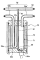
- FIG. 2 is a cross-sectional view showing a liquid reservoir 70 used in the refrigeration cycle apparatus A of the first embodiment.
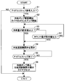
- FIG. 3 is a flowchart illustrating the flow of the cooling continuation control process in the refrigeration cycle apparatus A according to the first embodiment.
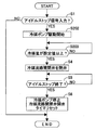
- FIG. 4 is a flowchart showing another process flow of the cooling continuation control.
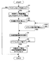
- FIG. 5 is a flowchart showing another processing flow of the cooling continuation control.
- the refrigeration cycle apparatus A according to the first embodiment will be described below with reference to FIGS. (Constitution) First, the configuration of the refrigeration cycle apparatus A of Example 1 will be described.
- the refrigeration cycle apparatus A according to the first embodiment is used in a vehicle air conditioner. As shown in FIG.
- the refrigeration cycle FC connected to is provided.
- the refrigerant flow path 50 includes a first flow path 51 that connects the outlet of the compressor 10 and the inlet of the condenser 20, and a second flow path 52 that connects the outlet of the condenser 20 and the inlet of the expander 30. And a third flow path 53 that connects the outlet of the expander 30 and the inlet of the evaporator 40, and a fourth flow path 54 that connects the outlet of the evaporator 40 and the inlet of the compressor 10.
- the compressor 10 is disposed in the engine room and driven by the engine Eng, and compresses and discharges the refrigerant in the refrigeration cycle apparatus A to high temperature and high pressure.
- the condenser 20 is disposed in the engine room and cools and liquefies the refrigerant compressed to high temperature and high pressure by the compressor 10 by heat exchange with the outside air.
- the expander 30 reduces the pressure and the flow rate of the high-pressure liquid refrigerant by passing through an expansion valve and an orifice so as to obtain a low-temperature and low-pressure liquid refrigerant.
- the evaporator 40 is disposed in the air conditioning unit ACU disposed in the vehicle interior together with the expander 30, and evaporates the low-temperature and low-pressure liquid refrigerant by exchanging heat with the air in the vehicle interior flowing in the air-conditioning unit ACU.
- a low-temperature and low-pressure gas refrigerant is used to cool the passenger compartment air to cool the passenger compartment.
- the third flow path 53 between the expander 30 and the evaporator 40 is provided with a refrigerant flow path opening / closing valve 60 that opens and closes the third flow path 53. Opening and closing of the refrigerant flow path opening / closing valve 60 is controlled by a control device 100 described later.
- a liquid reservoir 70 capable of storing the refrigerant is provided in the middle of the fourth flow path 54 connecting the evaporator 40 and the compressor 10. As shown in FIG. 2, the liquid reservoir 70 is provided on the outer periphery of the cylindrical tank body 71 that can store the refrigerant, and can exchange heat with the refrigerant stored in the tank body 71.
- the cold storage material 72 is provided.
- the cool storage material 72 what contains water and a highly water-absorbent resin (sodium polyacrylate), and well-known things, such as a paraffin, are used.
- the pipe 54 a on the upstream side of the fourth flow path 54 is opened at the top of the tank body 71, while the pipe 54 b on the downstream side of the fourth flow path 54 is connected to the tank body 71. It extends downward from the upper opening end 54 c, is curved upward by a curved portion 54 d of the lower part of the tank body 71, and is led out from the upper part of the tank body 71. Furthermore, a suction hole 54e for sucking the liquid refrigerant is formed in the curved portion 54d.
- a refrigerant pump 80 is provided at the bottom of the tank body 71. As shown in FIG. 1, the discharge path 81 connected to the refrigerant pump 80 is connected in the middle of the third flow path 53 upstream of the evaporator 40, and is connected to the liquid reservoir 70 sucked by the refrigerant pump 80. The stored liquid refrigerant is discharged into the third flow path 53.
- a check valve 82 is provided in the middle of the discharge passage 81 to restrict the direction of refrigerant flow only from the refrigerant pump 80 to the third flow path 53.
- a check valve 55 is provided in the middle of the pipe 54 b on the downstream side of the fourth flow path 54 to limit the direction of refrigerant flow only from the liquid reservoir 70 to the compressor 10.
- the operations of the refrigerant pump 80 and the refrigerant flow path opening / closing valve 60 described above are controlled by the control device 100.
- the control device 100 controls the operation of the air conditioning unit ACU, and is connected to a sensor group 101 that detects the cabin temperature, the outside temperature, and the like, and controls the operation of the air conditioning unit ACU based on the detection. Further, the control device 100 performs cooling continuation control for continuing the cooling operation by the evaporator 40 when the compressor 10 is stopped along with the stop of the engine Eng during execution of so-called idling stop control.
- the idling stop control is executed by the integrated controller 200 that controls the driving of the engine Eng, etc., and when the temporary stop during the running is detected, the driving of the engine Eng is stopped and the start operation is detected.
- the control device 100 determines the refrigerant flow path based on the input from the liquid refrigerant detection device 102 included in the sensor group 101 and the count value of the timer included in the control device 100.
- the operation of the on-off valve 60 and the refrigerant pump 80 is controlled.
- the liquid refrigerant detection device 102 is installed in the liquid reservoir 70 and detects whether or not the liquid refrigerant is present in the tank body 71 at a preset amount ser or more. It is possible to use one that has a float that floats or that detects the liquid level of the liquid refrigerant by using a sensor that electrically detects the presence or absence of liquid over a certain range in the height direction. .
- step S1 it is determined whether or not the idling stop signal sst has been input.
- the processing for the cooling continuation control in and after step S2 is executed and there is no input. In this case, the process is terminated without executing the cooling continuation control.
- step S2 the driving of the refrigerant pump 80 is started, and the timer built in the control device 100 is started to count up, and then the process proceeds to step S3.
- step S3 based on the output of the liquid refrigerant detection device 102, it is determined whether or not the amount of liquid refrigerant in the liquid reservoir 70 is equal to or larger than the set amount ser. If it is less than the amount ser, the process proceeds to step S7.
- This set amount ser is determined by experiment according to the vehicle type. In other words, the set amount ser is an amount of refrigerant that allows the cooling to continue for the time of executing the assumed idling stop, and includes the volume of the passenger compartment, the type of the air conditioner, and the cold storage of the cold storage material 72. The optimum value is determined by experiment for each vehicle type according to the ability.
- step S4 the refrigerant flow path opening / closing valve 60 is closed, and then the process proceeds to step S5.
- step S5 it is determined whether or not the idling stop is ended depending on whether or not the input of the idling stop signal sst is stopped. If the idling stop signal is ended, the process proceeds to step S6. If not, the refrigerant flow path opening / closing valve in step S4 is closed. Maintain valve status.
- step S6 which proceeds when the idling stop is terminated by stopping the input of the idling stop signal sst, the driving of the refrigerant pump 80 is stopped, the refrigerant flow path opening / closing valve 60 is returned to the initial valve open state, and the timer count-up is stopped. To do.
- step S7 that proceeds when the amount of liquid refrigerant is less than the set amount ser in step S3, it is determined whether or not the count value tc of the timer that started counting up in step S2 has exceeded a preset set value ts. To do.
- step S7 if the count value tc exceeds the set value ts, the process proceeds to step S4. If the count value tc does not exceed the set value ts, the determination in step S7 is repeated.
- the set value ts is a time set in advance based on experiments.
- the set value ts is determined based on the difference in pressure between the high pressure on the condenser 20 side and the low pressure on the evaporator 40 side for the amount of refrigerant necessary to continue cooling for a set time when idling is stopped. This is the time required to move from the side to the liquid reservoir 70. Therefore, this set value ts is set to a short time of less than 1 or 2 seconds, although it varies depending on the specifications of the vehicle, the air conditioning unit ACU, and the refrigeration cycle FC. (Function) Next, the operation of the first embodiment will be described.
- the refrigerant exchanges heat with the air in the passenger compartment in the evaporator 40, cools the air in the passenger compartment, evaporates into a low-temperature / low-pressure gas refrigerant, and sucks it into the compressor 10 through the liquid reservoir 70. Is done.
- the refrigerant absorbs heat from the cold storage material 72, and the cold storage material 72 is cooled.
- the load on the evaporator 40 decreases, and the refrigerant is liquefied and stored in the tank body 71 of the liquid reservoir 70.
- the refrigerant flowing into the tank body 71 from the pipe 54a on the upstream side of the fourth flow path 54 is stored in the lower part of the tank body 71, and the vaporized refrigerant is stored in the tank body 71. Accumulate on top of 71. Then, the vaporized refrigerant in the upper part is sucked from the opening end 54c of the downstream pipe 54b, and the liquid refrigerant in the lower part of the tank body 71 is slightly sucked and mixed into the compressor 10 in the suction hole 54e of the curved part 54d. Inhaled.
- the refrigerant contains lubricating oil. In order to supply this lubricating oil component to the compressor 10, liquid refrigerant is sucked from the suction hole 54e.
- idling stop control is executed based on the control of the general controller 200 when the vehicle is stopped, the drive of the compressor 10 is stopped as the drive of the engine Eng is stopped, and the high pressure from the compressor 10 is stopped. Discharge of the refrigerant is stopped.
- the control device 100 receives the idling stop signal sst, starts driving the refrigerant pump 80, and starts counting up the timer (steps S1 to S2). At this time, when the amount of liquid refrigerant detected by the liquid refrigerant detection device 102 of the liquid reservoir 70 is equal to or greater than a preset set amount ser, the refrigerant flow path opening / closing valve 60 is closed (steps S3 to S4).
- the low-pressure liquid refrigerant stored in the liquid reservoir 70 is sucked into the refrigerant pump 80 and supplied from the discharge path 81 to the evaporator 40 via the third flow path 53.
- the evaporator 40 evaporation of a liquid refrigerant is continued and the cooling by the evaporator 40 can be maintained.
- the refrigerant flow path opening / closing valve 60 is closed and the check valve 55 is provided in the fourth flow path 54 upstream of the compressor 10, the compressor 10 and the condenser 20.
- the high-pressure refrigerant on the side and the low-pressure refrigerant on the evaporator 40 and the reservoir 70 side are restricted from moving by the pressure difference, and are kept at a low pressure on the evaporator 40 side.
- the refrigerant vaporized in the evaporator 40 flows in.
- the heat storage material 72 absorbs heat, the pressure increase of the low-pressure refrigerant can be suppressed. Power can be maintained longer.
- the system waits for the refrigerant flow path opening / closing valve 60 to close.
- the amount of liquid refrigerant detected by the liquid refrigerant detection device 102 is equal to or greater than the set amount ser, or when the count value tc of the timer is equal to or greater than the set value ts, the refrigerant flow path opening / closing valve 60 is closed. That is, in the flowchart of FIG. 3, both determinations are repeated until YES is determined in steps S3 and S7, and one of the YES determinations proceeds to step S4.
- the open state of the refrigerant flow path opening / closing valve 60 is maintained until the amount of liquid refrigerant exceeds the set amount ser, Due to the pressure difference from the evaporator 40 side, the refrigerant on the condenser 20 side flows into the evaporator 40.
- the amount of refrigerant between the refrigerant flow path opening / closing valve 60 and the check valve 55 is not insufficient on the downstream side of the refrigerant flow path opening / closing valve 60, and cooling can be continued within the set time. it can.
- a liquid reservoir 70 is provided on the downstream side of the evaporator 40, a refrigerant flow path opening / closing valve 60 is provided between the expander 30 and the evaporator 40, and a liquid refrigerant detection device 102 is provided in the liquid reservoir 70.
- the control device 100 that opens and closes the refrigerant flow path opening / closing valve 60 opens the refrigerant flow path opening / closing valve 60 when the compressor 10 is driven, and based on the detection of the liquid refrigerant detection device 102 when the compressor 10 is stopped.
- the refrigerant flow path opening / closing valve 60 is closed. Therefore, when the compressor 10 is stopped as the engine Eng is stopped by the idling stop control, the refrigerant passage opening / closing valve 60 is closed to keep the evaporator 40 side at a low pressure and the cooling can be continued. it can.
- the regenerator material 72 can be cooled by the refrigerant that has evaporated in the evaporator 40 into a low-temperature and low-pressure gaseous state when the compressor 10 is in operation. Therefore, when the compressor 10 is stopped due to idling stop, in the liquid reservoir 70, the cold storage material 72 can absorb the heat of the refrigerant from the evaporator 40, and the pressure increase of the low-pressure refrigerant can be suppressed. Therefore, if the capacity
- the amount of refrigerant required at the time of idling stop is suppressed by the amount of cooling action by the regenerator material 72, the required capacity of the tank body 71 is suppressed, the liquid reservoir 70 is downsized, and the refrigeration cycle apparatus A is downsized. be able to.
- the control device 100 maintains the refrigerant flow path opening / closing valve 60 in the open state if the amount of liquid refrigerant in the liquid reservoir 70 is less than the set amount ser.
- the refrigerant flow path opening / closing valve 60 is closed when the amount exceeds the amount ser or the time of the set value ts has elapsed since the operation of the compressor 10 was stopped. For this reason, when the amount of liquid refrigerant in the liquid reservoir 70 is less than the set amount ser, the refrigerant on the condenser 20 side evaporates based on the pressure difference by delaying the closing timing of the refrigerant flow path opening / closing valve 60.
- the cooling maintenance time can be more reliably ensured. Moreover, even if the amount of liquid refrigerant in the liquid reservoir 70 is less than the set amount ser, the refrigerant flow path opening / closing valve 60 is closed when the elapsed time after the operation of the compressor 10 exceeds the set value ts.
- the liquid reservoir 70 includes a refrigerant pump 80 that sends the stored liquid refrigerant to the inlet of the evaporator 40, and the control device 100 operates the refrigerant pump 80 when the compressor 10 is stopped. For this reason, it is possible to supply the low-pressure liquid refrigerant to the evaporator 40 for a longer period of time and to ensure a longer cooling maintenance time when idling is stopped.
- Example 1 although the example which applied the refrigerant
- the power source of the compressor is not limited to the engine, and other power sources such as an electric motor may be used. For example, even in an electric vehicle or the like, cooling can be performed with the motor stopped and the compressor stopped.
- the cold storage material 72 is provided outside the tank body 71 in the liquid reservoir 70 , but the cold storage material 72 may be provided inside the tank body 71. Furthermore, it is not necessary to provide the cold storage material 72 in the liquid reservoir 70. Even in this case, the cooling can be maintained by ensuring the amount of refrigerant that can be cooled while the idling stop is performed in the liquid reservoir 70.
- the flow of the process for controlling the opening / closing of the refrigerant flow path opening / closing valve is not limited to that shown in the first embodiment, and the refrigerant flow path opening / closing valve is closed based on the detection of the liquid refrigerant detection device when the compressor is stopped. Any other processing flow may be used as long as it is a valve. Specifically, when the liquid refrigerant detection device can detect the amount of refrigerant in the liquid reservoir proportionally, the valve closing timing may be delayed as the amount decreases according to the amount.
- the valve when the detected liquid refrigerant amount when the compressor is stopped is less than the set amount ser, the set amount ser is detected or the valve is kept open until the set value ts has elapsed.
- the valve when the detected refrigerant amount is less than the set amount ser, the valve may be closed only in one of these cases. That is, as shown in the flowchart of FIG. 4, in step S202, only driving of the refrigerant pump 80 is started, and in the next step S203, if the refrigerant amount is less than the set amount ser, the determination in step S203 is repeated. Also good. Also, as shown in the flowchart of FIG. 5, when the count value tc is less than the set value ts in step S307, the determination in step S307 may be repeated.
- the refrigerant pump is driven immediately when the compressor is stopped.
- the refrigerant pump may be driven at least when the refrigerant flow path opening / closing valve is closed.
- the driving may be started in conjunction with the valve closing.
Landscapes
- Engineering & Computer Science (AREA)
- Physics & Mathematics (AREA)
- Thermal Sciences (AREA)
- Mechanical Engineering (AREA)
- General Engineering & Computer Science (AREA)
- Chemical & Material Sciences (AREA)
- Analytical Chemistry (AREA)
- Power Engineering (AREA)
- Air-Conditioning For Vehicles (AREA)
Abstract
L'invention porte sur un dispositif à cycle de réfrigération apte à allonger la durée du refroidissement. Le dispositif à cycle de réfrigération comprend : un cycle de réfrigération (FC) dans lequel un compresseur (10), un condenseur (20), un détendeur (30) et un évaporateur (40) sont reliés en série en boucle par un trajet d'écoulement de fluide frigorigène (50) ; un réservoir de fluide (70) disposé en aval de l'évaporateur (40) et apte à de retenir un fluide frigorigène et de fournir le fluide frigorigène à l'évaporateur (50) ; un dispositif de détection de fluide frigorigène liquide (102) destiné à détecter la quantité du fluide frigorigène liquide retenue dans le réservoir de liquide (70) ; une soupape (60) de coupure du trajet d'écoulement, disposée entre le détendeur (30) et l'évaporateur (40) et qui ouvre ou ferme le trajet d'écoulement de fluide frigorigène (50), et un dispositif de commande (100) servant à ouvrir la soupape (60) de coupure du trajet d'écoulement de fluide frigorigène lorsque le compresseur (10) est en marche et à fermer la soupape (60) de coupure du trajet d'écoulement de fluide frigorigène lorsque le compresseur (10) est arrêté, en fonction de la détection par le dispositif de détection de fluide frigorigène liquide (102).
Priority Applications (1)
| Application Number | Priority Date | Filing Date | Title |
|---|---|---|---|
| CN2012800056504A CN103328240A (zh) | 2011-02-04 | 2012-02-03 | 冷冻循环装置 |
Applications Claiming Priority (2)
| Application Number | Priority Date | Filing Date | Title |
|---|---|---|---|
| JP2011-022470 | 2011-02-04 | ||
| JP2011022470A JP2012162125A (ja) | 2011-02-04 | 2011-02-04 | 冷凍サイクル装置 |
Publications (1)
| Publication Number | Publication Date |
|---|---|
| WO2012105676A1 true WO2012105676A1 (fr) | 2012-08-09 |
Family
ID=46602876
Family Applications (1)
| Application Number | Title | Priority Date | Filing Date |
|---|---|---|---|
| PCT/JP2012/052456 Ceased WO2012105676A1 (fr) | 2011-02-04 | 2012-02-03 | Dispositif à cycle de réfrigération |
Country Status (3)
| Country | Link |
|---|---|
| JP (1) | JP2012162125A (fr) |
| CN (1) | CN103328240A (fr) |
| WO (1) | WO2012105676A1 (fr) |
Cited By (1)
| Publication number | Priority date | Publication date | Assignee | Title |
|---|---|---|---|---|
| WO2020049660A1 (fr) * | 2018-09-05 | 2020-03-12 | 三菱電機株式会社 | Dispositif à cycle frigorifique |
Families Citing this family (7)
| Publication number | Priority date | Publication date | Assignee | Title |
|---|---|---|---|---|
| KR101514924B1 (ko) * | 2014-05-22 | 2015-04-23 | 제주대학교 산학협력단 | 자동차 내부의 순간 냉방장치와 그에 의한 냉방법 |
| WO2018016221A1 (fr) * | 2016-07-22 | 2018-01-25 | 株式会社デンソー | Dispositif de climatisation de véhicule |
| JP6597713B2 (ja) | 2016-07-22 | 2019-10-30 | 株式会社デンソー | 車両用空調装置 |
| CN110087922B (zh) * | 2017-03-30 | 2022-05-17 | 马瑞利(中国)汽车空调有限公司 | 蓄冷热交换器 |
| EP4286773A1 (fr) * | 2022-06-01 | 2023-12-06 | Carrier Corporation | Unité de réfrigération de transport et procédé de mesure de la quantité de réfrigérant dans celle-ci |
| CN115437426B (zh) * | 2022-09-30 | 2023-08-15 | 江苏拓米洛高端装备股份有限公司 | 一种恒温箱控制系统及其控制方法 |
| CN116424056B (zh) * | 2023-03-01 | 2025-12-19 | 小米汽车科技有限公司 | 一种车载空调系统及车载空调系统的控制方法 |
Citations (6)
| Publication number | Priority date | Publication date | Assignee | Title |
|---|---|---|---|---|
| JPS6268115A (ja) * | 1985-09-20 | 1987-03-28 | Sanden Corp | 自動車用空調装置の制御装置 |
| JP2000313226A (ja) * | 1999-05-06 | 2000-11-14 | Nissan Motor Co Ltd | 自動車用空気調和装置 |
| JP2003285633A (ja) * | 2002-03-29 | 2003-10-07 | Denso Corp | 車両用空調装置 |
| JP2006021571A (ja) * | 2004-07-06 | 2006-01-26 | Toyota Motor Corp | 車両用空調装置 |
| JP2006509678A (ja) * | 2002-12-16 | 2006-03-23 | ダイムラークライスラー・アクチェンゲゼルシャフト | 特に自動車用の空調装置 |
| JP2009229014A (ja) * | 2008-03-24 | 2009-10-08 | Denso Corp | 蓄冷器付き冷凍サイクル装置 |
-
2011
- 2011-02-04 JP JP2011022470A patent/JP2012162125A/ja not_active Withdrawn
-
2012
- 2012-02-03 WO PCT/JP2012/052456 patent/WO2012105676A1/fr not_active Ceased
- 2012-02-03 CN CN2012800056504A patent/CN103328240A/zh active Pending
Patent Citations (6)
| Publication number | Priority date | Publication date | Assignee | Title |
|---|---|---|---|---|
| JPS6268115A (ja) * | 1985-09-20 | 1987-03-28 | Sanden Corp | 自動車用空調装置の制御装置 |
| JP2000313226A (ja) * | 1999-05-06 | 2000-11-14 | Nissan Motor Co Ltd | 自動車用空気調和装置 |
| JP2003285633A (ja) * | 2002-03-29 | 2003-10-07 | Denso Corp | 車両用空調装置 |
| JP2006509678A (ja) * | 2002-12-16 | 2006-03-23 | ダイムラークライスラー・アクチェンゲゼルシャフト | 特に自動車用の空調装置 |
| JP2006021571A (ja) * | 2004-07-06 | 2006-01-26 | Toyota Motor Corp | 車両用空調装置 |
| JP2009229014A (ja) * | 2008-03-24 | 2009-10-08 | Denso Corp | 蓄冷器付き冷凍サイクル装置 |
Cited By (4)
| Publication number | Priority date | Publication date | Assignee | Title |
|---|---|---|---|---|
| WO2020049660A1 (fr) * | 2018-09-05 | 2020-03-12 | 三菱電機株式会社 | Dispositif à cycle frigorifique |
| JPWO2020049660A1 (ja) * | 2018-09-05 | 2021-08-12 | 三菱電機株式会社 | 冷凍サイクル装置 |
| JP6991346B2 (ja) | 2018-09-05 | 2022-01-12 | 三菱電機株式会社 | 冷凍サイクル装置 |
| US11802722B2 (en) | 2018-09-05 | 2023-10-31 | Mitsubishi Electric Corporation | Refrigeration cycle apparatus |
Also Published As
| Publication number | Publication date |
|---|---|
| JP2012162125A (ja) | 2012-08-30 |
| CN103328240A (zh) | 2013-09-25 |
Similar Documents
| Publication | Publication Date | Title |
|---|---|---|
| WO2012105676A1 (fr) | Dispositif à cycle de réfrigération | |
| JP4522641B2 (ja) | 蒸気圧縮式冷凍機 | |
| JP4581720B2 (ja) | エジェクタを用いたサイクル | |
| CN101213410A (zh) | 冷冻装置 | |
| CN104220821B (zh) | 空调装置 | |
| KR20140092803A (ko) | 냉동 사이클 장치 및 그것을 구비한 공기 조화기 | |
| WO2018110236A1 (fr) | Système de circuit de réfrigérant, dispositif de commande et procédé de commande | |
| CN110234944B (zh) | 制冷系统 | |
| KR200471061Y1 (ko) | 냉각시스템 | |
| JP2020104591A (ja) | 車両用空調装置 | |
| CN117906320A (zh) | 气液分离器、空调系统及运行控制方法 | |
| JP2005214575A (ja) | 冷凍装置 | |
| JP4665601B2 (ja) | エジェクタを用いたサイクル | |
| JP2017190938A (ja) | 冷凍サイクル装置 | |
| CN107576144B (zh) | 一种冰箱的停机方法和装置 | |
| WO2013114461A1 (fr) | Unité de climatisation et unité de climatisation pour véhicule de chemin de fer | |
| CN1296661C (zh) | 冷冻装置 | |
| CN107560205B (zh) | 一种冰箱的开机方法和装置 | |
| CN107560204B (zh) | 一种冰箱 | |
| CN100378411C (zh) | 带有喷射器的蒸汽压缩制冷剂循环系统 | |
| JP6632423B2 (ja) | 冷凍サイクル、およびこの冷凍サイクルを用いた車両用の空調システム | |
| KR101314620B1 (ko) | 냉장고의 제어방법 | |
| KR20160096947A (ko) | 공기조화기 및 그 제어방법 | |
| KR101837985B1 (ko) | 소음저감을 위한 냉동사이클을 구비한 복합냉장고 | |
| JP2010025418A (ja) | 冷凍装置 |
Legal Events
| Date | Code | Title | Description |
|---|---|---|---|
| 121 | Ep: the epo has been informed by wipo that ep was designated in this application |
Ref document number: 12742281 Country of ref document: EP Kind code of ref document: A1 |
|
| NENP | Non-entry into the national phase |
Ref country code: DE |
|
| 122 | Ep: pct application non-entry in european phase |
Ref document number: 12742281 Country of ref document: EP Kind code of ref document: A1 |