WO2012108302A1 - Dispositif d'iris - Google Patents
Dispositif d'iris Download PDFInfo
- Publication number
- WO2012108302A1 WO2012108302A1 PCT/JP2012/052113 JP2012052113W WO2012108302A1 WO 2012108302 A1 WO2012108302 A1 WO 2012108302A1 JP 2012052113 W JP2012052113 W JP 2012052113W WO 2012108302 A1 WO2012108302 A1 WO 2012108302A1
- Authority
- WO
- WIPO (PCT)
- Prior art keywords
- slide pin
- spring
- wire spring
- blade
- diaphragm
- Prior art date
- Legal status (The legal status is an assumption and is not a legal conclusion. Google has not performed a legal analysis and makes no representation as to the accuracy of the status listed.)
- Ceased
Links
Images



Classifications
-
- G—PHYSICS
- G03—PHOTOGRAPHY; CINEMATOGRAPHY; ANALOGOUS TECHNIQUES USING WAVES OTHER THAN OPTICAL WAVES; ELECTROGRAPHY; HOLOGRAPHY
- G03B—APPARATUS OR ARRANGEMENTS FOR TAKING PHOTOGRAPHS OR FOR PROJECTING OR VIEWING THEM; APPARATUS OR ARRANGEMENTS EMPLOYING ANALOGOUS TECHNIQUES USING WAVES OTHER THAN OPTICAL WAVES; ACCESSORIES THEREFOR
- G03B9/00—Exposure-making shutters; Diaphragms
- G03B9/02—Diaphragms
- G03B9/06—Two or more co-operating pivoted blades, e.g. iris type
Definitions
- the present invention relates to an aperture device for an optical device such as a compact digital camera or a single-lens reflex camera.
- the present invention relates to an aperture device that can smoothly open and close following changes in the brightness of a subject during moving image shooting.
- Conventional diaphragm devices include a type in which a plurality of diaphragm blades are driven by an annular windmill that rotates about an optical axis to open and close an optical path opening. Pins are planted on each diaphragm blade or ground plate, cam grooves are formed on the ground plate or each diaphragm blade, and each pin engages with the edge of each cam groove by rotating each diaphragm blade with a windmill. When pressed, each diaphragm blade rotates about the rotation fulcrum to open and close the optical path opening.
- a diaphragm device that urges the blade body of the diaphragm blades with a leaf spring and urges the slide pin to the edge of the cam groove has been proposed.
- the leaf spring needs to have a certain width. Then, the spring constant becomes high and the fluctuation of the urging force becomes large, which is not preferable. Further, when the blade body is made of resin, there is a problem that when the blade body is biased, the blade body is bent and deformed.
- the present invention has been made in view of the above problems, and an object of the present invention is to provide a diaphragm device that can smoothly drive the diaphragm blades by eliminating backlash between the pin and the cam groove when the diaphragm blades are opened and closed. .
- a diaphragm device includes a blade body that narrows an opening of an optical path and a slide pin, a diaphragm blade that narrows the opening of the optical path, and a cam plate having a cam groove that guides the slide pin And further comprising a wire spring that urges the slide pin, and the wire spring has a free posture with no urging force at the open limit position of the aperture blade. A clearance opens between the spring and the slide pin.
- the slide pin of the diaphragm blade is urged toward the edge of the cam groove by the wire spring to eliminate the play between the pin and the cam groove, the diaphragm blade can be smoothly opened and closed. .
- the pressure is always applied from the wire spring to the aperture blades at positions close to the aperture, which is sensitive to the aperture other than the open limit position, the slide pin is unlikely to move suddenly and opens and closes smoothly. can do. In this way, there is no sudden change in aperture due to hysteresis in the opening / closing direction and changes in gravity / inertial force applied to the camera, and in particular, aperture performance during moving image / continuous shooting of a single-lens reflex camera is improved.
- the urging force (pressurization) applied to the diaphragm blades is zero at the diaphragm opening limit, and the diaphragm blades fluctuate. However, at the opening limit, a very high diaphragm performance is not required, so that no particular problem occurs.
- the open optical path opening may be determined by a fixed opening such as a base plate or a cover, without using the diaphragm blades. It should be noted that the urging force on the diaphragm blades is zero at the diaphragm opening limit, but if the diaphragm blades are rotated, the slide pin comes into contact with the wire spring. Energize.
- the range where the urging force of the diaphragm blades is zero is preferably a range of about 10% or less near the open limit.
- the wire spring is in a free posture with no urging force when the aperture is fully open. That is, in the open limit position, the pressure of the wire spring is zero, and there is a clearance between the spring and the pin. Therefore, at the time of assembly, after placing the diaphragm blades at a predetermined position at the open end of one ground plate, the wire spring may be placed on the other ground plate (the reverse order may be used). Alternatively, if you assemble a part that incorporates the spring in a free position (base plate, cam plate, cover, etc.) and a part that incorporates the aperture blade in the open limit position, the spring and aperture blade automatically open Assembled into.
- the aperture blade can be incorporated without artificially deforming the wire spring.
- the wire spring is thin, it is preferable to avoid touching the wire spring as much as possible at the time of assembly because permanent deformation of the wire spring and change in spring characteristics can be avoided. In addition, the number of steps in the assembly process is reduced.
- the spring biases the slide pin of the diaphragm blade, there is no problem such as deformation of the blade body (light path shielding film portion) that occurs when the blade body of the diaphragm blade is biased.
- a leaf spring having a certain width and a relatively high spring constant (a wire spring works well on the side of the film-like diaphragm blade body). Since the wire spring is used in the present invention, the spring constant can be lowered, and the urging force and its variation can be reduced.
- an opening / closing drive mechanism for the diaphragm blades there is a type in which the cam plate is rotated without using the windmill, in addition to a system in which the pins of the plurality of diaphragm blades are rotated through the windmill.
- the aperture blade opening / closing drive mechanism may be a manual aperture type that does not use an actuator such as a motor.
- a diaphragm device includes a blade body for narrowing an opening of an optical path and a slide pin, a diaphragm blade for narrowing the opening of the optical path, and a cam plate having a cam groove for guiding the slide pin And further comprising a wire spring that urges the slide pin, the wire spring abutting and sliding on a surface of the slide pin closer to the optical path center, and the slide The pin is biased in the outward direction of the optical path.
- the wire spring abuts and slides on the surface of the slide pin on the optical path opening side, and urges the pin outward (in the direction opposite to the center direction of the optical path opening).
- the operating region of the wire spring is not near the outer periphery of the diaphragm device but near the optical path opening. That is, since the vicinity of the outer periphery of the diaphragm device is an area that does not interfere with the operation of the wire spring, the engaging portion between the diaphragm device and the lens barrel and the attachment portion for other parts can be arranged near the outer periphery of the diaphragm device.
- the wire spring when the wire spring is arranged outside the diaphragm blade and the diaphragm blade is urged inward (toward the center of the optical path opening), the wire spring is present near the outer periphery of the diaphragm device. Then, interference with the movement of the wire spring becomes a problem, and there is a restriction on the arrangement of the engaging portion between the diaphragm device and the lens barrel and the mounting portion of other components. That is, as in the present invention, the wire spring is brought into contact with and slides on the surface on the optical path opening side and is urged outwardly from the optical path opening. The degree of freedom of expansion / contraction of the outer diameter of the device will increase.
- the wire spring abuts and slides on the surface of the slide pin near the center of the optical path, and the slide pin moves in the optical path outward direction. It is preferable to energize.
- the wire spring since the wire spring contacts and slides on the surface of the slide pin on the optical path opening side, the wire spring is in a free posture at the limit when the pin comes to the outer position, and between the spring and the pin at the time of the limit. Easy to open the gap.
- the wire spring has a spoiled winding portion, a hook arm connected to one end of the spiral winding portion, and a slide pin abutting arm connected to the other end, and a spring on the cam plate A fulcrum boss and a spring hook boss are erected, and the spiral winding portion of the wire spring is engaged with the spring fulcrum boss of the cam plate, and the hook arm is engaged with the spring hook boss. Is preferred.
- the wire spring can be easily set on the cam plate simply by fitting the spline winding portion of the wire spring to the spring fulcrum boss of the cam plate and engaging the hook arm with the spring hook boss.
- a diaphragm device is a cam plate having a blade body for narrowing an opening of an optical path and a slide pin, a diaphragm blade for narrowing the opening of the optical path, and a cam groove for guiding the slide pin And a wire spring that urges the slide pin, and the diameter of the wire spring is 0.2 mm or less.
- the diameter of the wire spring is preferably 0.2 mm or less.
- the diameter of the wire spring is preferably 0.15 mm or less, more preferably 0.1 mm or less.
- the material of the spring is preferably a stainless steel wire, a hard copper wire, a drawn copper wire or the like, but other spring materials are also applicable.
- the spring constant of the wire spring is 0.01 to 2.20 gf ⁇ mm / deg.
- the spring constant of the wire spring is preferably 0.02 to 0.15 gf ⁇ mm / deg, more preferably 0.05 to 0.10 gf ⁇ mm / deg.
- the urging force of the wire spring is 0.10 to 25 gf ⁇ mm.
- the urging force of the wire spring is preferably 0.25 to 1.50 gf ⁇ mm, more preferably 0.40 to 1.30 gf ⁇ mm.
- the number of windings of the spoiled winding portion of the wire spring is 1 to 6 times.
- the number of windings is preferably 1 to 5 times, more preferably 1 to 3 times.
- the spring constant decreases while the thickness of the spring increases. It is preferable to reduce the spring constant by increasing the number of turns while suppressing an increase in thickness by using a thin wire spring.
- wire spring wire diameter A wire spring having an urging force capable of countering the self-weight and inertia moment applied to the diaphragm blades is selected.
- B The motor startability is not deteriorated beyond the practical range.
- C Fit in the required space. Based on these conditions, settings are made as follows. (1) Since each part such as a motor and diaphragm blades is arranged in the required space, and a wire spring is arranged in the remaining restricted space, the shape of the wire spring is almost determined from now on.
- the size and weight of the diaphragm blades are almost determined.
- the position where the urging force of the wire spring becomes zero is, for example, 10% of the rotation stroke of the diaphragm blade from the closed limit to the open position, which is close to the open limit (with the pin stroke) of 10%. % Is preferred.
- the moment of gravity around the rotation fulcrum pin of the diaphragm blade / the moment of biasing force is in the range of 1/2 to 1/650.
- the moment ratio is more preferably 1/10 to 1/100, and most preferably 1/20 to 1/50.
- the “gravity moment around the rotation fulcrum pin of the diaphragm blade” is “weight of one diaphragm blade ⁇ distance between the rotation fulcrum pin and the gravity center of the blade”.
- the “biasing force moment” is “linear spring biasing force ⁇ distance between the rotation fulcrum pin and the slide pin.
- the slide pin of the diaphragm blade is urged toward the edge of the cam groove by the wire spring to eliminate backlash between the pin and the cam groove. Smooth opening / closing operation of the blades becomes possible. Furthermore, if the urging force (pressurization) applied to the diaphragm blades is zero at the aperture opening limit, that is, if the wire spring has a free posture with no urging force, the wire spring and the diaphragm blade can be incorporated independently, Undesirable permanent deformation and change in spring characteristics of the wire spring can be avoided. In addition, the number of man-hours for the assembly process can be reduced.
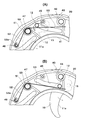
- FIG. 1A and 1B are diagrams illustrating a diaphragm device according to an embodiment of the present invention.
- FIG. 1A is a plan view when fully opened, and FIG. 1B is a plan view when fully closed (a cover is omitted). ). It is the figure which expanded a part of Drawing 1 (A) and Drawing 1 (B). It is a disassembled perspective view of the diaphragm
- FIG. 5A is a plan view of the wire spring, and FIG. 5B is a plan view showing a state in which the wire spring is housed in the base plate B.
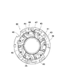
- FIG. 3 is an exploded perspective view of the diaphragm device of the present invention.
- the diaphragm device 1 includes a plurality of diaphragm blades 10 (seven in this example, only one is shown in FIG. 1) for narrowing the optical path opening, and a windmill 20 that rotates the diaphragm blades 10 around the optical axis OA. And a base plate A30 and a base plate B (cam plate) 40 in which an optical path opening is formed, a wire spring 50 that urges each diaphragm blade 10, and a cover 60 that holds the wire spring 50.
- All the diaphragm blades 10 have the same shape, and include a blade body 11 and a slide pin 12 implanted in the blade body 11.
- the blade body 11 is made of, for example, a resin film (in one example, a polyester film) that has been coated with a light shielding ability.
- the blade body 11 is substantially semicircular, and an arcuate diaphragm forming edge 11a is formed on the inner periphery.
- An optical path centered on the optical axis OA is formed by the diaphragm forming edge 11 a of each blade member 10.
- the slide pin 12 is implanted at the end of one surface of each blade body 11.
- a rotation fulcrum pin 15 of the diaphragm blade 10 is implanted on the opposite surface of each blade body 11.
- the windmill 20 is a ring-shaped thin member.
- the wind turbine 20 has the same number (7 in this example) of holes 21 as the number of aperture blades 10 formed at equal intervals.
- the rotation fulcrum pins 15 of the diaphragm blades 10 are fitted into the holes 21 so that the diaphragm blades 10 can rotate around the holes 21.
- a protrusion 23 is formed on a part of the outer periphery of the windmill 20 so as to project outward. This protrusion 23 is for positioning the windmill 20.
- a rack 25 is formed on a part of the outer periphery. As will be described later, the rack 25 meshes with a pinion 36 fixed to the rotating shaft of a motor 35 attached to the main plate A30.
- the windmill 20 rotates about the optical axis OA by the rotation of the motor 35.
- the base plate A30 and the base plate B40 have substantially the same hollow disc shape, and optical path openings 31 and 41 are formed in the center.
- the aperture blade 10 and the windmill 20 are supported between the main plate A30 and the main plate B.
- Around the optical path opening 31 on one surface of the base plate A30 is a concave portion 33 on which the diaphragm blades 10 and the windmill 20 are placed.
- a motor 35 is attached to the opposite surface of the main plate A30.
- the rotation shaft of the motor 35 protrudes into the recess 33 through the ground plane A30.
- a pinion 36 that meshes with the rack 25 of the wind turbine 20 is fixed to the protruding rotating shaft.
- the base plate B40 (cam plate) will be described with reference to FIG.
- a periphery of the optical path opening 41 on one surface of the ground plane B40 (a surface opposite to the ground plane A30) is a concave portion 43 in which a later-described wire spring 50 is accommodated.
- the recess 43 is formed with the same number of cam grooves 45 as the number of diaphragm blades 10 (seven in this example).
- the cam groove 45 has the same shape and is formed obliquely from the outside to the inside of the main plate B40.
- the slide pin 12 of the diaphragm blade 10 is engaged with the cam groove 45.
- a spring fulcrum boss 47 is erected on the side of each cam groove 45 in the recess 43. Further, a spring hooking boss 48 is erected on the side of each spring fulcrum boss 47 opposite to the cam groove 45.
- each of the recesses 33 and 43 of the base plate A30 and the base plate B40 there are protrusions, recesses, and holes that are engaging portions with the lens barrel and other parts (control electronic components PI and the like).
- a notch or the like is formed.
- the wire spring 50 will be described with reference to FIG. 5A is a plan view of the wire spring, and FIG. 5B is a diagram showing a state in which the wire spring is set on the ground plane B.
- FIG. The wire spring 50 is a torsion spring, and as shown in FIG. 5A, a spoiled winding portion 51, a hook arm 52 connected to one end of the spiral winding portion 51, and a slide connected to the other end. And a pin abutting arm 53.
- the tip 52a of the hook arm 52 is folded back into a U shape.
- the angle between the arms 52 and 53 in the free posture is 115.87 ° (design value).
- the material of the wire spring 50 is preferably a stainless steel wire, a hard copper wire, a drawn copper wire or the like, and preferably has a lower spring constant. This is because the lower the spring constant, the smaller the fluctuation of the urging force of the pin 12 of the diaphragm blade 10.
- the spring constant is 0.01 to 2.20 gf ⁇ mm / deg, preferably 0.02 to 0.15 gf ⁇ mm / deg, more preferably 0.04 to 0.10 gf ⁇ mm / deg. It is selected to satisfy either condition.
- the diameter of the wire spring is 0.2 mm or less, preferably 0.15 mm or less, more preferably 0.1 mm or less. A thinner wire diameter is preferable because the spring thickness can be reduced.
- the urging force moment of the wire spring is 0.10 to 25 gf ⁇ mm, preferably 0.25 to 1.50 gf ⁇ mm, more preferably 0.40 to 1.30 gf ⁇ mm.
- the number of turns of the spoiled winding portion of the wire spring is 1 to 6 times, preferably 1 to 5 times, more preferably 1 to 3 times.
- the height of the winding portion is as low as possible because the diaphragm device can be thinned.
- the spring constant varies depending on the diameter of the optical path opening of the diaphragm device, the shape / weight / number of diaphragm blades, the outer diameter of the diaphragm device, etc., but is selected to be as low as possible.
- the arm length of the spring varies depending on the number of blades. An example of setting each item will be described later.
- the spiral winding portion 51 is fitted into the spring fulcrum boss 47 erected in the concave portion 43 of the main plate B40, and the folded portion 52a at the tip of the hook arm 52 is provided.
- a spring hook boss 48 is hooked and attached.
- the cover 60 is a thin ring-shaped member that closes the concave portion 43 of the ground plane B 40 and holds the wire spring 50 in the concave portion 43.
- a groove having the same shape as the groove is formed at the same position as the cam groove 45 of the base plate B40. Further, a hole through which each spring fulcrum boss 47 and the spring hook boss 48 are erected on the base plate B40 is formed.
- each figure (A) shows when fully open, and each figure (B) shows when fully closed. In each figure, the cover 60 is omitted.
- the apertures are fully opened as shown in FIGS. 1A and 2A, the aperture forming edges 11a of all aperture blades 10 are positioned slightly outside the optical path openings 31, 41 of the ground plane A30 and the ground plane B40, and the optical path The openings 31 and 41 are fully open.
- the slide pin 12 of each diaphragm blade 10 is located at the outer end of the cam groove 45 of the main plate B40.
- the slide pin abutting arm 53 of the wire spring 50 is located inside the slide pin 12 (on the optical path opening side), and the arm 53 and the slide pin 12 are not in contact with each other and the gap C is open. That is, the wire spring 50 is in a natural posture with no load applied, and no pressure is applied to the slide pin 12.
- the rack 25 of the windmill 20 is engaged with a pinion 36 fixed to the output shaft of the motor 35.
- the motor 35 is driven and the pinion 36 rotates, the windmill 20 starts to rotate in the clockwise direction in FIG. 1 about the optical axis OA via the rack 25.
- each aperture blade 10 penetrate
- the slide pin 12 of each diaphragm blade 10 is located at the outer end of the cam groove 45 of the main plate B40.
- the slide pin 12 is located outside the slide pin contact arm 53 of the wire spring 50 (on the side opposite to the optical path opening) and is not in contact with the arm 53. That is, no pressure is applied to the slide pin 12 from the wire spring 50. Since the slide pin 12 and the cam groove 45 are designed to have some clearance between them, the diaphragm blades 10 are slightly fluctuated in a natural state, but a high degree of diaphragm performance is not required when fully opened, which is particularly problematic. Does not happen
- the slide pin 12 advances along the cam groove 45 as described above. Then, since the slide pin contact arm 53 of the wire spring 50 exists in the moving direction of the slide pin 12, the slide pin 12 eventually contacts the outside of the slide pin contact arm 53. When the slide pin 12 further advances in the cam groove 45, the slide pin 12 automatically pushes the slide pin abutting arm 53 of the wire spring 50 inward (on the optical path opening side). In other words, the slide pin 12 is pressed against the outer edge of the cam groove 45 by applying a pressure from the slide pin abutting arm 53 in the outward direction (the side opposite to the optical path opening).
- the slide pin 12 advances in the cam groove 45 in a state where the slide pin abuts the arm 53 and is pressed against the outer edge of the cam groove 45, that is, in a state where there is no clearance (backlash) from the cam groove 45. Since the slide pin abutting arm 53 extends beyond the inner end of the cam groove 45, the slide pin 12 moves to the arm 53 until the slide pin 12 reaches the inner end of the cam groove 45 (until the optical path opening is fully closed). Receive the reaction force.
- the motor 35 when opening an optical path, the motor 35 is reversely rotated to rotate the windmill 20 in the opposite direction. Also in this case, since the slide pin 12 of the aperture blade 10 continues to receive the reaction force in the outward direction from the slide pin abutting arm 53 of the wire spring 50, the slide pin 12 is free from play with the cam groove 45. Then, the cam groove 45 advances outward.
- the slide pin 12 is urged toward the edge of the cam groove 45 by the wire spring 50 to eliminate the play between the pin 12 and the cam groove 45, so that the aperture blade 10 can be opened and closed smoothly. Operation is possible.
- the pressure is always applied from the wire spring 50 to the diaphragm blade 10, so that the slide pin 12 (the diaphragm blade 10) is unlikely to move rapidly.
- the spring constant of the wire spring 50 is small, fluctuations in the urging force can be reduced.
- the diaphragm device of the present invention has the following advantages. (1) When fully opened, the urging force (pressure) applied to the aperture blade 10 is zero and the wire spring 50 is in a free posture, so that the aperture blade 10 and the wire spring 50 can be incorporated independently. Specifically, the diaphragm blade 10 may be placed so as to be fully opened with respect to the windmill 20 installed in the recess 33 of the ground plane A30, and then the wire spring 50 may be placed at a predetermined position on the ground plane B40. Or the reverse order may be sufficient. Since the wire spring 50 is thin and easily deformed, it is preferable to avoid touching it as much as possible at the time of assembly.
- the aperture blade 10 can be incorporated without artificially deforming the wire spring 50. For this reason, an undesirable permanent deformation of the wire spring 50 and a change in spring characteristics can be avoided. In addition, the number of steps in the assembly process is reduced.
- the slide pin contact arm 53 of the wire spring 50 contacts and slides on the surface of the slide pin 12 on the optical path opening side. That is, the wire spring 50 exists relatively on the optical path opening side of the ground plane B40. For this reason, the operation region of the wire spring 50 is a portion closer to the center (the optical path opening side) of the base plate B40, and the outer peripheral portions of the base plates A and B30, 40 do not interfere with the operation region of the wire spring 50. Accordingly, an engaging portion with a lens barrel or the like and an attachment portion for other components can be arranged on the outer peripheral portion. This increases the degree of freedom in setting the space between the lens barrel and the diaphragm (enlargement of the aperture diameter, expansion / contraction of the outer diameter of the diaphragm, etc.).
- a slide pin is implanted in the aperture blade, a cam groove is formed in the base plate B, and the aperture blade is rotated by a windmill. It is possible to use various mechanisms if it is assumed to be planted. For example, it is good also as providing a cam groove in a windmill and rotating an aperture blade.
- the aperture blade opening / closing drive mechanism of the present invention can be a manual aperture type that does not use an actuator such as a motor.
- the number of aperture blades is seven, but other numbers are possible.
- a larger number of blades is preferable because the length of the slide pin abutting arm of the wire spring can be shortened, so that the processing accuracy of the wire spring is improved and deformation at the time of incorporation and handling is small.
- Diaphragm opening diameter ⁇ 16.0 mm
- Wire spring wire diameter 0.1 mm
- Material Stainless steel
- Spring constant 0.041 gf ⁇ mm / deg
- Energizing moment 0.46 gf ⁇ mm (when fully closed)
- Number of turns of spiral wound portion 5.18 times.
- Diaphragm blade weight 0.005 g
- Distance between slide pin and pivot pin 4.18mm The distance between the pivot point and the optical path opening center is 11.29 mm.
Landscapes
- Physics & Mathematics (AREA)
- General Physics & Mathematics (AREA)
- Diaphragms For Cameras (AREA)
Abstract
[Problème] Le but de l'invention est de fournir un dispositif d'iris permettant d'actionner en douceur des lames d'iris en éliminant le jeu entre les broches et les renfoncements de came lors d'une opération d'ouverture et de fermeture des lames d'iris. [Solution] À cette fin, un dispositif d'iris (1) comprend : des lames d'iris (10) sur lesquelles sont disposées des broches coulissantes (12) ; des plaques de cames (40) comprenant en outre des renfoncements de came (45) qui dirigent les broches coulissantes (12) ; et des ressorts filaires (50) qui entraînent les broches coulissantes (12). Les ressorts filaires (50) coulissent en contact avec les faces latérales d'ouverture du trajet de lumière des broches coulissantes (12) des lames d'iris (10), et poussent les broches (12) vers les bords des renfoncements de came (45), éliminant le jeu entre les broches et les renfoncements de came et permettant des opérations d'ouverture-fermeture en douceur des lames d'iris (10). En outre, dans la position d'ouverture maximale des lames d'iris (10), les ressorts filaires (50) ont une attitude libre, n'étant pas soumis à une force de poussée, ce qui ouvre des jours entre les ressorts (50) et les broches coulissantes (12).
Applications Claiming Priority (2)
| Application Number | Priority Date | Filing Date | Title |
|---|---|---|---|
| JP2011026969A JP5134697B2 (ja) | 2011-02-10 | 2011-02-10 | 絞り装置 |
| JP2011-026969 | 2011-02-10 |
Publications (1)
| Publication Number | Publication Date |
|---|---|
| WO2012108302A1 true WO2012108302A1 (fr) | 2012-08-16 |
Family
ID=46638518
Family Applications (1)
| Application Number | Title | Priority Date | Filing Date |
|---|---|---|---|
| PCT/JP2012/052113 Ceased WO2012108302A1 (fr) | 2011-02-10 | 2012-01-31 | Dispositif d'iris |
Country Status (3)
| Country | Link |
|---|---|
| JP (1) | JP5134697B2 (fr) |
| TW (1) | TW201303481A (fr) |
| WO (1) | WO2012108302A1 (fr) |
Cited By (4)
| Publication number | Priority date | Publication date | Assignee | Title |
|---|---|---|---|---|
| EP3731013A4 (fr) * | 2017-12-19 | 2021-08-18 | Nittoh Inc. | Dispositif à diaphragme et barrillet d'objectif |
| TWI818767B (zh) * | 2022-10-13 | 2023-10-11 | 和碩聯合科技股份有限公司 | 葉片結構及鏡頭裝置 |
| CN119356010A (zh) * | 2024-11-06 | 2025-01-24 | 佛山柏瑞光电技术有限公司 | 一种光圈弹性叶片及自动调节的光圈结构 |
| US20250068036A1 (en) * | 2023-08-21 | 2025-02-27 | Samsung Electro-Mechanics Co., Ltd. | Aperture module and camera module including the same |
Families Citing this family (4)
| Publication number | Priority date | Publication date | Assignee | Title |
|---|---|---|---|---|
| TWI557347B (zh) * | 2014-01-09 | 2016-11-11 | 華邦電子股份有限公司 | 蝕刻反應設備及其節流閥 |
| JP7600812B2 (ja) | 2021-03-26 | 2024-12-17 | 株式会社ニコン | 絞りユニットおよびレンズ鏡筒 |
| TWI814457B (zh) * | 2022-05-26 | 2023-09-01 | 大立光電股份有限公司 | 通光孔模組、相機模組與電子裝置 |
| TWI833383B (zh) | 2022-09-22 | 2024-02-21 | 大立光電股份有限公司 | 可變光圈模組、成像鏡頭模組與電子裝置 |
Citations (3)
| Publication number | Priority date | Publication date | Assignee | Title |
|---|---|---|---|---|
| JP2002051509A (ja) * | 2000-08-01 | 2002-02-15 | Asmo Co Ltd | 直流電動機におけるブラシ保持装置及び直流電動機の組立方法 |
| JP2005024640A (ja) * | 2003-06-30 | 2005-01-27 | Nidec Copal Corp | カメラ用羽根駆動機構 |
| JP2006126653A (ja) * | 2004-10-29 | 2006-05-18 | Canon Inc | 撮像装置、及び絞り兼用瞳分割機構 |
Family Cites Families (4)
| Publication number | Priority date | Publication date | Assignee | Title |
|---|---|---|---|---|
| JPH0624813Y2 (ja) * | 1988-04-01 | 1994-06-29 | 株式会社コパル | 羽根開閉機構 |
| JPH11160754A (ja) * | 1997-11-28 | 1999-06-18 | Asahi Optical Co Ltd | カメラの絞り機構 |
| JP2000089294A (ja) * | 1998-09-11 | 2000-03-31 | Seiko Precision Inc | カメラの羽根開閉装置 |
| JP5178216B2 (ja) * | 2008-01-30 | 2013-04-10 | キヤノン株式会社 | 光量調節装置及びカメラ |
-
2011
- 2011-02-10 JP JP2011026969A patent/JP5134697B2/ja not_active Expired - Fee Related
-
2012
- 2012-01-31 WO PCT/JP2012/052113 patent/WO2012108302A1/fr not_active Ceased
- 2012-02-09 TW TW101104195A patent/TW201303481A/zh unknown
Patent Citations (3)
| Publication number | Priority date | Publication date | Assignee | Title |
|---|---|---|---|---|
| JP2002051509A (ja) * | 2000-08-01 | 2002-02-15 | Asmo Co Ltd | 直流電動機におけるブラシ保持装置及び直流電動機の組立方法 |
| JP2005024640A (ja) * | 2003-06-30 | 2005-01-27 | Nidec Copal Corp | カメラ用羽根駆動機構 |
| JP2006126653A (ja) * | 2004-10-29 | 2006-05-18 | Canon Inc | 撮像装置、及び絞り兼用瞳分割機構 |
Cited By (5)
| Publication number | Priority date | Publication date | Assignee | Title |
|---|---|---|---|---|
| EP3731013A4 (fr) * | 2017-12-19 | 2021-08-18 | Nittoh Inc. | Dispositif à diaphragme et barrillet d'objectif |
| TWI818767B (zh) * | 2022-10-13 | 2023-10-11 | 和碩聯合科技股份有限公司 | 葉片結構及鏡頭裝置 |
| US20250068036A1 (en) * | 2023-08-21 | 2025-02-27 | Samsung Electro-Mechanics Co., Ltd. | Aperture module and camera module including the same |
| US12541137B2 (en) * | 2023-08-21 | 2026-02-03 | Samsung Electro-Mechanics Co., Ltd. | Aperture module and camera module including the same |
| CN119356010A (zh) * | 2024-11-06 | 2025-01-24 | 佛山柏瑞光电技术有限公司 | 一种光圈弹性叶片及自动调节的光圈结构 |
Also Published As
| Publication number | Publication date |
|---|---|
| JP5134697B2 (ja) | 2013-01-30 |
| JP2012168237A (ja) | 2012-09-06 |
| TW201303481A (zh) | 2013-01-16 |
Similar Documents
| Publication | Publication Date | Title |
|---|---|---|
| JP5134697B2 (ja) | 絞り装置 | |
| JP5015225B2 (ja) | 絞り装置 | |
| US20190137845A1 (en) | Blade driving device and image capturing device | |
| CN101878449B (zh) | 减速机构、驱动装置和光学器具 | |
| JP2006053409A (ja) | 光量調整装置及びこれを用いた撮像装置 | |
| EP2163946B1 (fr) | Obturateur à plan focal et appareil de capture d'images | |
| JP2012168508A (ja) | 絞り装置 | |
| US5365298A (en) | Camera shutter with oscillation damping | |
| GB2615646A (en) | Actuator assembly | |
| JP2014145820A (ja) | バリア装置、レンズ鏡筒およびそれを備える撮像装置 | |
| JP5753070B2 (ja) | フォーカルプレーンシャッタ及びそれを備えた光学機器 | |
| JP5858655B2 (ja) | 光量調整装置 | |
| JP2015049430A (ja) | 光量調整装置 | |
| WO2012120735A1 (fr) | Dispositif d'actionnement de lame et dispositif optique | |
| JP2017223811A (ja) | 羽根駆動装置及び撮像装置 | |
| JP2015079200A (ja) | 撮像装置 | |
| JP2018200336A (ja) | 光量調整装置 | |
| JP5256613B2 (ja) | 絞り機構及び光学機器 | |
| JP2016133627A (ja) | 絞り装置及びそれを有するレンズ装置及び撮像装置 | |
| JP2006171405A (ja) | カメラのレンズバリア装置 | |
| JP2016143052A (ja) | 光量調整装置、及びそれを備えたカメラ | |
| JP5952155B2 (ja) | 絞り装置およびレンズ鏡筒 | |
| JP5953098B2 (ja) | 絞り装置及び光学機器 | |
| JP2017138449A (ja) | レンズ鏡筒およびそれを用いた光学機器並びにレンズ鏡筒の製造方法 | |
| CN120871511A (zh) | 可变光圈模块及影像撷取装置 |
Legal Events
| Date | Code | Title | Description |
|---|---|---|---|
| 121 | Ep: the epo has been informed by wipo that ep was designated in this application |
Ref document number: 12744492 Country of ref document: EP Kind code of ref document: A1 |
|
| NENP | Non-entry into the national phase |
Ref country code: DE |
|
| 122 | Ep: pct application non-entry in european phase |
Ref document number: 12744492 Country of ref document: EP Kind code of ref document: A1 |