WO2012120559A1 - Système de chauffage de siège de véhicule - Google Patents
Système de chauffage de siège de véhicule Download PDFInfo
- Publication number
- WO2012120559A1 WO2012120559A1 PCT/JP2011/001333 JP2011001333W WO2012120559A1 WO 2012120559 A1 WO2012120559 A1 WO 2012120559A1 JP 2011001333 W JP2011001333 W JP 2011001333W WO 2012120559 A1 WO2012120559 A1 WO 2012120559A1
- Authority
- WO
- WIPO (PCT)
- Prior art keywords
- vehicle seat
- heater
- reinforcing sheet
- side portion
- heater wire
- Prior art date
- Legal status (The legal status is an assumption and is not a legal conclusion. Google has not performed a legal analysis and makes no representation as to the accuracy of the status listed.)
- Ceased
Links
Images

Classifications
-
- B—PERFORMING OPERATIONS; TRANSPORTING
- B60—VEHICLES IN GENERAL
- B60N—SEATS SPECIALLY ADAPTED FOR VEHICLES; VEHICLE PASSENGER ACCOMMODATION NOT OTHERWISE PROVIDED FOR
- B60N2/00—Seats specially adapted for vehicles; Arrangement or mounting of seats in vehicles
- B60N2/90—Details or parts not otherwise provided for
- B60N2/986—Side-rests
- B60N2/99—Side-rests adjustable
-
- B—PERFORMING OPERATIONS; TRANSPORTING
- B60—VEHICLES IN GENERAL
- B60N—SEATS SPECIALLY ADAPTED FOR VEHICLES; VEHICLE PASSENGER ACCOMMODATION NOT OTHERWISE PROVIDED FOR
- B60N2/00—Seats specially adapted for vehicles; Arrangement or mounting of seats in vehicles
- B60N2/56—Heating or ventilating devices
- B60N2/5678—Heating or ventilating devices characterised by electrical systems
- B60N2/5685—Resistance
-
- H—ELECTRICITY
- H05—ELECTRIC TECHNIQUES NOT OTHERWISE PROVIDED FOR
- H05B—ELECTRIC HEATING; ELECTRIC LIGHT SOURCES NOT OTHERWISE PROVIDED FOR; CIRCUIT ARRANGEMENTS FOR ELECTRIC LIGHT SOURCES, IN GENERAL
- H05B3/00—Ohmic-resistance heating
- H05B3/20—Heating elements having extended surface area substantially in a two-dimensional [2D] plane, e.g. plate-heater
- H05B3/34—Heating elements having extended surface area substantially in a two-dimensional [2D] plane, e.g. plate-heater flexible, e.g. heating nets or webs
-
- H—ELECTRICITY
- H05—ELECTRIC TECHNIQUES NOT OTHERWISE PROVIDED FOR
- H05B—ELECTRIC HEATING; ELECTRIC LIGHT SOURCES NOT OTHERWISE PROVIDED FOR; CIRCUIT ARRANGEMENTS FOR ELECTRIC LIGHT SOURCES, IN GENERAL
- H05B2203/00—Aspects relating to Ohmic resistive heating covered by group H05B3/00
- H05B2203/002—Heaters using a particular layout for the resistive material or resistive elements
- H05B2203/003—Heaters using a particular layout for the resistive material or resistive elements using serpentine layout
-
- H—ELECTRICITY
- H05—ELECTRIC TECHNIQUES NOT OTHERWISE PROVIDED FOR
- H05B—ELECTRIC HEATING; ELECTRIC LIGHT SOURCES NOT OTHERWISE PROVIDED FOR; CIRCUIT ARRANGEMENTS FOR ELECTRIC LIGHT SOURCES, IN GENERAL
- H05B2203/00—Aspects relating to Ohmic resistive heating covered by group H05B3/00
- H05B2203/014—Heaters using resistive wires or cables not provided for in H05B3/54
-
- H—ELECTRICITY
- H05—ELECTRIC TECHNIQUES NOT OTHERWISE PROVIDED FOR
- H05B—ELECTRIC HEATING; ELECTRIC LIGHT SOURCES NOT OTHERWISE PROVIDED FOR; CIRCUIT ARRANGEMENTS FOR ELECTRIC LIGHT SOURCES, IN GENERAL
- H05B2203/00—Aspects relating to Ohmic resistive heating covered by group H05B3/00
- H05B2203/029—Heaters specially adapted for seat warmers
Definitions
- the present invention relates to a vehicle seat heater mounted on a vehicle seat.
- a vehicle seat heater that is arranged between a seat cover and a seat pad (seat body) of a vehicle seat for an automobile or the like and warms a person seated on the vehicle seat.
- the vehicle seat heater is configured, for example, by disposing a heater wire on a flexible base sheet as described in Patent Document 1.
- the vehicle seat heater described in Patent Literature 1 includes a central portion that is disposed at a seat central portion of the vehicle seat and a side portion that is disposed at a seat side portion.
- the seat side portion of the vehicle seat is deformed mainly in the lateral direction due to contact with the person when the person sits in the center part of the seat or leaves the seat.
- the side portion of the vehicle seat heater disposed in the seat side portion is also deformed in the lateral direction. If the deformation of the wrinkle line is repeated in the side portion of the vehicle seat heater, there is a possibility of disconnection at the portion of the heater line that intersects the wrinkle line.
- an object of the present invention is to suppress the disconnection of the heater wire in the side portion of the vehicle seat heater disposed in the seat side portion of the vehicle seat.
- the present invention is configured as follows.
- a vehicle seat heater that is mounted on a vehicle seat and includes a base sheet and a heater wire disposed on the base sheet, wherein the seat side portion of the vehicle seat is provided.
- a reinforcing sheet affixed to a side part disposed on the edge of the reinforcing sheet, the edge of the reinforcing sheet having at least a portion extending in the front-rear direction of the side part and facing the front side of the side part.
- An area for arranging the heater wire is provided between the portions to be operated.
- the wrinkle line is generated at a position that does not intersect the heater line along a portion that extends in the front-rear direction of the edge of the reinforcing sheet and faces the edge.
- the reinforcing sheet can suppress the generation of wrinkle lines in the wiring region of the heater wire between the portion where the reinforcing sheet is attached, that is, the portion where the edge of the reinforcing sheet is opposed. Thereby, disconnection of the heater wire is suppressed in the side portion of the vehicle seat heater.
- FIG. 1 The perspective view of a vehicle seat provided with the vehicle seat heater of one embodiment concerning the present invention.
- Top view of the vehicle seat heater shown in FIG. The enlarged view of the side part of the vehicle seat heater shown in FIG.
- FIG. 1 The enlarged view of the side part of the vehicle seat heater of another embodiment which concerns on this invention
- One aspect of the present invention is a vehicle seat heater that is mounted on a vehicle seat and includes a base sheet and a heater wire disposed on the base sheet, and is disposed in a seat side portion of the vehicle seat.
- a reinforcing sheet affixed to the side portion, and the edge of the reinforcing sheet includes at least a portion extending in the front-rear direction of the side portion and facing the front portion of the side portion.
- the vehicle seat heater is provided with an area for arranging the heater wire therebetween.
- the wrinkle line is generated at a position that does not intersect the heater line along a portion that extends in the front-rear direction of the edge of the reinforcing sheet and faces the edge.
- the reinforcing sheet can suppress the generation of wrinkle lines in the wiring region of the heater wire between the portion where the reinforcing sheet is attached, that is, the portion where the edge of the reinforcing sheet is opposed. Thereby, disconnection of the heater wire is suppressed in the side portion of the vehicle seat heater.
- the heater wire may extend from the rear side of the side portion and be folded back at the front side of the side portion.
- the reinforcing sheet is the upper side of the vehicle seat heater, and the heater wire and the A shape that overlaps at least a region surrounded on three sides by the heater wire is provided. Thereby, a wrinkle line is generated at a position that does not intersect the heater wire along the edge of the reinforcing sheet.
- the reinforcing sheet may have a V-shaped front end. Therefore, even if the front end of the seat side portion of the vehicle seat is deformed in a direction other than the lateral direction, the wrinkle line is generated along the edge of the V-shaped front end of the reinforcing sheet without crossing the heater wire. .
- the reinforcing sheet may be attached to the surface of the base sheet on which the heater wire is disposed. Thereby, a heater wire is pinched and protected between a reinforcement sheet and a base material sheet.
- the facing portions of the edge of the reinforcing sheet may be linear.
- wrinkle lines extending in the front-rear direction of the side portion of the vehicle seat heater which are likely to occur due to lateral deformation of the seat side portion of the vehicle seat, are generated along the opposing portions of the edge of the reinforcing seat.
- the heater wire may be arranged on the side portion so as not to be orthogonal to a virtual straight line extending in the front-rear direction of the side portion. Thereby, disconnection of the heater wire due to repeated deformation of the portion where the reinforcing sheet is affixed, that is, the wiring region of the heater wire, in the horizontal direction can be suppressed.
- FIG. 1 shows a vehicle seat provided with a vehicle seat heater according to an embodiment of the present invention.
- FIG. 2 is a top view of the vehicle seat heater of FIG.
- the vehicle seat 50 includes a plurality of seat covers made of, for example, artificial leather, and a seat pad (seat body) covered with the seat cover and made of, for example, a urethane farm. .
- the vehicle seat heater 10 is disposed between the seat cover and the seat pad. Further, the vehicle seat heater 10 is disposed from the central portion 50a of the vehicle seat 50 that supports the human buttocks, to the front portion 50b that supports the thighs, and to the seat side portion 50c that is located beside the central portion 50a. Has been.
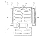
- the vehicle seat heater 10 includes a base sheet 12, a heater wire 14 disposed on the base sheet 12, and a harness 16 that supplies electric power to the heater wire 14.
- the vehicle seat heater 10 also includes a central portion 10a disposed in the central portion 50a and the front portion 50b of the vehicle seat 50, and a side portion 10b disposed in the seat side portion 50c.
- the base sheet 12 of the vehicle seat heater 10 is made of, for example, a nonwoven fabric.
- the heater wire 14 of the vehicle seat heater 10 is a metal wire, for example, and is sewn to the base material sheet 12 with a thread (not shown). Alternatively, the heater wire 14 may be sewn into the base sheet 12 like a thread, or may be bonded by heat welding or the like. In short, the method for fixing the heater wire 14 to the base sheet 12 is not limited to sewing.
- the heater wire 14 extends from the harness 16 attached to the rear end of the central portion 10a toward the front end of the one side portion 10b, and is folded back at the front end of the side portion 10b so as to return to the central portion 10a. Yes.
- front-rear direction refers to the front-rear direction of the vehicle seat 50.
- lateral direction refers to a direction orthogonal to the “front-rear direction”.
- an arrow F indicates “forward direction”.
- the vehicle seat heater 10 further includes a reinforcing sheet 18 attached to the side portion 10b.
- the reinforcing sheet 18 is for controlling the generation of wrinkle lines so that the wrinkle lines do not intersect the heater wires 14 in the side portion 10b of the vehicle seat heater 10.
- the seat side portion 50 c of the vehicle seat 50 is as shown by an arrow D by contact with a person when the person sits on or leaves the central portion 50 a. , Deforms mainly in the horizontal direction.
- the side portion 10b of the vehicle seat heater 10 is also deformed mainly in the lateral direction.
- the wrinkle line extended in the front-back direction of the side part 10b may generate
- the reinforcing sheet 18 is configured to control the generation of wrinkle lines so that the wrinkle lines do not intersect the heater wires 14 in the side portion 10b.
- the reinforcing sheet 18 is made of the same material as that of the base sheet 12 (including a case where the thickness is different), or a material such as a resin film that is less likely to cause wrinkle lines than the base sheet 12. ing.
- the reinforcing sheet 18 preferably has a flexibility that does not impair the cushioning property of the seat side portion 50c of the vehicle seat 50.
- the portion where the reinforcing sheet 18 is attached has high rigidity, and as a result, the generation of wrinkle lines at the portion is suppressed.
- the reinforcing sheet 18 also includes edge portions 18a that extend in the front-rear direction of the side portion 10b and face each other. A region where the heater wire 14 is disposed is provided between the edge portions 18a.
- the reinforcing sheet 18 is at least in the region 12a of the base sheet 12 surrounded by the heater wire 14 and the heater wire 14 when viewed from above the vehicle seat heater 10 (that is, FIGS. 2 and 3). It has an overlapping shape.
- the wrinkle line R is changed as shown in FIG. It occurs along the edge portion 18 a of the reinforcing sheet 18. Therefore, if the reinforcing sheet 18 is attached to the side portion 10b so that the heater wire 14 is positioned between the opposing edge portions 18a, the wrinkle line R generated along the edge portion 18a is at least on the front side of the side portion 10b. , The heater wire 14 can be prevented from crossing.
- the wrinkle line R generated along the edge portion 18 a of the reinforcing sheet 18 extends from the front end to the rear end of the side portion 10 b of the vehicle seat heater 10.
- a wrinkle line R is generated on the front side of the portion 10b (or a deep wrinkle line is generated on the front side as compared with the rear side).
- the reason for this is that, as shown in FIG. 1, the rear side of the seat side portion 50c of the vehicle seat 50 is close to the backrest portion 50d, so that it is greater due to contact with the person than the front side of the seat side portion 50c. This is because the possibility of deformation is low. Therefore, in FIG. 3, although the heater wire 14 intersects the wrinkle line R on the rear side of the side portion 10b, the possibility of disconnection at that point is low.
- the edge portion 18a of the reinforcing sheet 18 is preferably linear, but is partially refracted or arranged in an arc shape in accordance with the shape of the vehicle seat heater. It doesn't matter.
- the side portion 10b of the vehicle seat heater 10 has a straight line extending in the front-rear direction even when the reinforcing seat 18 is not present. Wrinkle lines are likely to occur.
- the edge portion 18a is preferably linear.
- the edge of the reinforcing sheet 18 is not limited to a straight line.
- the wrinkle line generated along or in contact with the edge is at least on the front side of the side portion 10b of the vehicle seat heater 10. It does not have to cross the heater wire.
- the wrinkle line R intersects the heater wire 14 along the portion 18a that extends in the front-rear direction of the edge of the reinforcing sheet 18 and faces the edge. Occurs at a position that does not.
- the reinforcing sheet 18 can suppress the generation of wrinkle lines in the wiring region of the heater wire 14 between the portion where the reinforcing sheet 18 is attached, that is, the portion 18 a facing the edge of the reinforcing sheet 18. Thereby, in the side part 10b of the vehicle seat heater 10, disconnection of the heater wire 14 is suppressed.
- the reinforcing sheet attached to the side portion of the vehicle seat heater is not limited to the shape shown in FIG.
- FIG. 4 shows a reinforcing sheet of another form different from the reinforcing sheet 18 shown in FIG.
- the reinforcing sheet 118 shown in FIG. 4 has an outline parallel to the heater wire 14 disposed on the side portion 10b of the vehicle seat heater 10 as viewed from above the vehicle seat heater 10, and includes the heater wire 14 and the heater.
- a shape that overlaps at least the region 12 a of the base sheet 12 surrounded on three sides by the line 14 is provided.
- the heater wire 14 disposed on the side portion 10b of the vehicle seat heater 10 includes two straight portions 14a extending linearly from the rear end to the front end of the side portion 10b, And a V-shaped portion 14b connecting the front end of the straight portion 14a.
- the reinforcing sheet 118 includes an edge portion 118a extending in parallel with the straight portion 14a of the heater wire 14, and an edge portion 118b extending in parallel with the V-shaped portion 14b to define a V-shaped tip.
- a wrinkle line R1 is generated mainly along the edge portion 118a, and a wrinkle line R2 is generated along the edge portion 118b. Neither of the wrinkle lines R1 and R2 intersects the heater wire 14 on the front side of the side portion 10b.
- the reinforcing sheet has a contour extending in parallel with the heater wire as in the reinforcing sheet 118, there is an advantage that less material is required for producing the reinforcing sheet.
- the front end of the seat side part of the vehicle seat is touched by the back of a person's thigh when seating or leaving the seat, for example, deformation other than the lateral direction, especially in the oblique direction (the direction between the lateral direction and the front-rear direction) Deformation is likely to occur. Therefore, like the reinforcing sheet 118 shown in FIG. 4, the front end of the reinforcing sheet is preferably V-shaped. Thereby, even if the front end of the seat side portion of the vehicle seat is deformed in a direction other than the lateral direction, the wrinkle line is generated along the edge of the V-shaped front end of the reinforcing sheet without crossing the heater wire. .
- the reinforcing sheet according to the present invention is at least the front side of the side part of the vehicle seat heater, and the longitudinal direction of the side part. It is possible to take various shapes on the premise of having edge portions extending and facing each other.
- the reinforcing sheet 18 is attached to the surface of the base sheet 12 on which the heater wire 14 is disposed to protect the heater wire 14. If protection is not required, the reinforcing sheet 18 may be attached to the opposite surface. As described above, the reinforcing sheet 18 suppresses the generation of wrinkle lines in the portion where the reinforcing sheet 18 is affixed, and generates wrinkle lines along the edge portion 18a. Even if it is attached to either of the two surfaces, its function is not impaired.
- the reinforcing sheet 18 has a size extending from the front end to the rear end of the side portion 10b of the vehicle seat heater 10, but the present invention is not limited thereto. Absent.
- a reinforcing sheet having a size that extends from the front end of the side portion 10b to the approximate center of the side portion 10b may be used. The reason is that, as described above, a wrinkle line is mainly generated on the front side of the side portion 10 b of the vehicle seat heater 10.
- the heater wire disposed on the side portion of the vehicle seat heater is disposed on the side portion so as not to be orthogonal to the front-rear direction of the side portion (the virtual straight line extending in the front-rear direction). preferable.
- the reinforcing sheet has flexibility as described above, generation of wrinkle lines is suppressed in the side part of the vehicle seat heater to which the reinforcing sheet is attached, but it does not limit deformation in that part. . Therefore, with the lateral deformation of the seat side portion of the vehicle seat, the portion to which the reinforcing sheet is attached also deforms in the lateral direction. As shown in FIGS. 3 and 4, the heater wire is not attached to the side portion so as not to be orthogonal to the front-rear direction of the side portion of the vehicle seat heater so that the heater wire is not disconnected by repeating such deformation. It is preferable to be disposed.
- the present invention is not limited to the vehicle seat heater 10 disposed in the central portion 50a, the front portion 50b, and the seat side portion 50c of the vehicle seat 50 shown in FIG. 1, but is provided in a backrest portion that supports a human back. It is also possible to use a vehicle seat heater.
Landscapes
- Engineering & Computer Science (AREA)
- Aviation & Aerospace Engineering (AREA)
- Transportation (AREA)
- Mechanical Engineering (AREA)
- Chair Legs, Seat Parts, And Backrests (AREA)
- Surface Heating Bodies (AREA)
- Seats For Vehicles (AREA)
- Resistance Heating (AREA)
- Air-Conditioning For Vehicles (AREA)
Abstract
Priority Applications (5)
| Application Number | Priority Date | Filing Date | Title |
|---|---|---|---|
| US13/259,531 US20120228277A1 (en) | 2011-03-07 | 2011-03-07 | Vehicle seat heater |
| EP11860548.4A EP2684740B1 (fr) | 2011-03-07 | 2011-03-07 | Système de chauffage de siège de véhicule |
| JP2011545559A JP5750578B2 (ja) | 2011-03-07 | 2011-03-07 | 車両用シートヒータ |
| PCT/JP2011/001333 WO2012120559A1 (fr) | 2011-03-07 | 2011-03-07 | Système de chauffage de siège de véhicule |
| CN201180001890.2A CN103097184B (zh) | 2011-03-07 | 2011-03-07 | 车辆用座椅加热器 |
Applications Claiming Priority (1)
| Application Number | Priority Date | Filing Date | Title |
|---|---|---|---|
| PCT/JP2011/001333 WO2012120559A1 (fr) | 2011-03-07 | 2011-03-07 | Système de chauffage de siège de véhicule |
Publications (1)
| Publication Number | Publication Date |
|---|---|
| WO2012120559A1 true WO2012120559A1 (fr) | 2012-09-13 |
Family
ID=46794577
Family Applications (1)
| Application Number | Title | Priority Date | Filing Date |
|---|---|---|---|
| PCT/JP2011/001333 Ceased WO2012120559A1 (fr) | 2011-03-07 | 2011-03-07 | Système de chauffage de siège de véhicule |
Country Status (5)
| Country | Link |
|---|---|
| US (1) | US20120228277A1 (fr) |
| EP (1) | EP2684740B1 (fr) |
| JP (1) | JP5750578B2 (fr) |
| CN (1) | CN103097184B (fr) |
| WO (1) | WO2012120559A1 (fr) |
Cited By (1)
| Publication number | Priority date | Publication date | Assignee | Title |
|---|---|---|---|---|
| JP2016173877A (ja) * | 2015-02-27 | 2016-09-29 | 寿工業株式会社 | 面状発熱体 |
Families Citing this family (5)
| Publication number | Priority date | Publication date | Assignee | Title |
|---|---|---|---|---|
| US10314111B2 (en) * | 2013-05-02 | 2019-06-04 | Gentherm Gmbh | Liquid resistant heating element |
| WO2014199595A1 (fr) * | 2013-06-10 | 2014-12-18 | パナソニックIpマネジメント株式会社 | Chauffage de siège |
| JP6561544B2 (ja) * | 2015-04-06 | 2019-08-21 | テイ・エス テック株式会社 | 車両用シート |
| CN112172633A (zh) * | 2019-07-03 | 2021-01-05 | 和美汽车零部件青县有限公司 | 一种汽车加热坐垫 |
| JP6829405B2 (ja) * | 2019-07-24 | 2021-02-10 | テイ・エス テック株式会社 | 車両用シート |
Citations (2)
| Publication number | Priority date | Publication date | Assignee | Title |
|---|---|---|---|---|
| JPH065352A (ja) * | 1992-06-18 | 1994-01-14 | Matsushita Electric Ind Co Ltd | 車両用座席のヒータユニット |
| JP2003173859A (ja) * | 2001-12-05 | 2003-06-20 | Matsushita Electric Ind Co Ltd | シートヒータ |
Family Cites Families (13)
| Publication number | Priority date | Publication date | Assignee | Title |
|---|---|---|---|---|
| JPS63115574A (ja) * | 1986-11-04 | 1988-05-20 | 加藤 正己 | 浴用遠赤外線装置 |
| GB8704232D0 (en) * | 1987-02-24 | 1987-04-01 | Raychem Sa Nv | Electrical device |
| JPH0252608A (ja) * | 1988-08-17 | 1990-02-22 | Matsushita Electric Ind Co Ltd | 車両用シートヒータ |
| DE4101290C2 (de) * | 1991-01-17 | 1994-11-03 | Ruthenberg Gmbh Waermetechnik | Elektrisches Flächenheizelement |
| JP2559404Y2 (ja) * | 1991-12-19 | 1998-01-19 | 株式会社クラベ | フィルムヒータ |
| CA2393970C (fr) * | 1999-12-10 | 2004-07-20 | Thermion Systems International | Dispositif de chauffage de stratifie thermoplastique et procede de fabrication associe |
| JP4000886B2 (ja) * | 2002-04-04 | 2007-10-31 | マツダ株式会社 | 車両のシート装置 |
| DE10394000D2 (de) * | 2002-10-23 | 2005-09-08 | Braincom Ag | Flächenheizung, Verfahren zu deren Herstellung und heizbarer Gegenstand sowie Sitzbelegungserkennung, Sitz damit und Sitzbelegungserkennungsverfahren |
| JP2006134672A (ja) * | 2004-11-04 | 2006-05-25 | Taisei Laminator Co Ltd | 面状発熱体、および面状発熱体を用いた発熱ブロック |
| DE102005002693B3 (de) * | 2005-01-19 | 2006-09-14 | F. S. Fehrer Automotive Foam Gmbh | Polsterelement mit Sitzheizung |
| DE102005050459B3 (de) * | 2005-10-19 | 2007-03-15 | I.G. Bauerhin Gmbh | Flexibles Flächenheizelement, insbesondere für Sitzheizungen, und Verfahren zur Herstellung eines flexiblen Heizelements |
| US7500536B2 (en) * | 2006-09-27 | 2009-03-10 | Illinois Tool Works Inc. | Seat heater with occupant sensor |
| JP5304895B2 (ja) * | 2009-05-26 | 2013-10-02 | パナソニック株式会社 | 面状採暖具およびこれを備えた座席 |
-
2011
- 2011-03-07 CN CN201180001890.2A patent/CN103097184B/zh active Active
- 2011-03-07 JP JP2011545559A patent/JP5750578B2/ja active Active
- 2011-03-07 WO PCT/JP2011/001333 patent/WO2012120559A1/fr not_active Ceased
- 2011-03-07 US US13/259,531 patent/US20120228277A1/en not_active Abandoned
- 2011-03-07 EP EP11860548.4A patent/EP2684740B1/fr active Active
Patent Citations (2)
| Publication number | Priority date | Publication date | Assignee | Title |
|---|---|---|---|---|
| JPH065352A (ja) * | 1992-06-18 | 1994-01-14 | Matsushita Electric Ind Co Ltd | 車両用座席のヒータユニット |
| JP2003173859A (ja) * | 2001-12-05 | 2003-06-20 | Matsushita Electric Ind Co Ltd | シートヒータ |
Cited By (1)
| Publication number | Priority date | Publication date | Assignee | Title |
|---|---|---|---|---|
| JP2016173877A (ja) * | 2015-02-27 | 2016-09-29 | 寿工業株式会社 | 面状発熱体 |
Also Published As
| Publication number | Publication date |
|---|---|
| US20120228277A1 (en) | 2012-09-13 |
| CN103097184A (zh) | 2013-05-08 |
| EP2684740A1 (fr) | 2014-01-15 |
| EP2684740A4 (fr) | 2014-08-27 |
| EP2684740B1 (fr) | 2016-10-26 |
| JP5750578B2 (ja) | 2015-07-22 |
| CN103097184B (zh) | 2016-01-20 |
| JPWO2012120559A1 (ja) | 2014-07-07 |
Similar Documents
| Publication | Publication Date | Title |
|---|---|---|
| JP5750578B2 (ja) | 車両用シートヒータ | |
| JP5653365B2 (ja) | 車両用シートヒータ | |
| CN102910097B (zh) | 车辆座椅 | |
| US10245988B2 (en) | Vehicle seat provided with seat belt retractor | |
| JP6013530B2 (ja) | 乗物用シート | |
| JP6299704B2 (ja) | 車両用シート | |
| US20120267939A1 (en) | Vehicle net seat | |
| JP2019026232A (ja) | シートヒータ及びそれを備えるシートカバー | |
| JP6533156B2 (ja) | 車両用シート | |
| JP5613613B2 (ja) | 車両用シート | |
| JP2020128116A (ja) | シートヒータ | |
| JP2015228355A (ja) | 電装品 | |
| JP7157834B2 (ja) | 乗物用シート | |
| JP2022190117A5 (fr) | ||
| JP6053465B2 (ja) | 乗物用シート | |
| JP4965155B2 (ja) | 車両用シート | |
| JP2012192761A (ja) | 車両用シート | |
| JP6298596B2 (ja) | 車両用シート | |
| JP5589828B2 (ja) | 車両用シート | |
| KR20110007980U (ko) | 유동 방지식 차량용 시트커버 | |
| KR101039723B1 (ko) | 열선이 부착된 시트패드 커버 | |
| JP7824823B2 (ja) | 車両用シートのフレーム構造及び車両用シート | |
| JP7099268B2 (ja) | 乗物用シートフレーム | |
| JP2024049236A (ja) | 制御用ヒータ、及びシートヒータ | |
| JP6036317B2 (ja) | 布帛における接続部材の絶縁構造 |
Legal Events
| Date | Code | Title | Description |
|---|---|---|---|
| WWE | Wipo information: entry into national phase |
Ref document number: 201180001890.2 Country of ref document: CN |
|
| WWE | Wipo information: entry into national phase |
Ref document number: 13259531 Country of ref document: US |
|
| ENP | Entry into the national phase |
Ref document number: 2011545559 Country of ref document: JP Kind code of ref document: A |
|
| 121 | Ep: the epo has been informed by wipo that ep was designated in this application |
Ref document number: 11860548 Country of ref document: EP Kind code of ref document: A1 |
|
| REEP | Request for entry into the european phase |
Ref document number: 2011860548 Country of ref document: EP |
|
| WWE | Wipo information: entry into national phase |
Ref document number: 2011860548 Country of ref document: EP |
|
| NENP | Non-entry into the national phase |
Ref country code: DE |