WO2012120601A1 - ダイカスト鋳造装置及び鋳造製品の離型方法 - Google Patents
ダイカスト鋳造装置及び鋳造製品の離型方法 Download PDFInfo
- Publication number
- WO2012120601A1 WO2012120601A1 PCT/JP2011/055125 JP2011055125W WO2012120601A1 WO 2012120601 A1 WO2012120601 A1 WO 2012120601A1 JP 2011055125 W JP2011055125 W JP 2011055125W WO 2012120601 A1 WO2012120601 A1 WO 2012120601A1
- Authority
- WO
- WIPO (PCT)
- Prior art keywords
- mold
- casting apparatus
- cast product
- releasing
- die casting
- Prior art date
- Legal status (The legal status is an assumption and is not a legal conclusion. Google has not performed a legal analysis and makes no representation as to the accuracy of the status listed.)
- Ceased
Links
Images





Classifications
-
- B—PERFORMING OPERATIONS; TRANSPORTING
- B22—CASTING; POWDER METALLURGY
- B22D—CASTING OF METALS; CASTING OF OTHER SUBSTANCES BY THE SAME PROCESSES OR DEVICES
- B22D17/00—Pressure die casting or injection die casting, i.e. casting in which the metal is forced into a mould under high pressure
- B22D17/20—Accessories: Details
- B22D17/22—Dies; Die plates; Die supports; Cooling equipment for dies; Accessories for loosening and ejecting castings from dies
-
- B—PERFORMING OPERATIONS; TRANSPORTING
- B22—CASTING; POWDER METALLURGY
- B22D—CASTING OF METALS; CASTING OF OTHER SUBSTANCES BY THE SAME PROCESSES OR DEVICES
- B22D17/00—Pressure die casting or injection die casting, i.e. casting in which the metal is forced into a mould under high pressure
- B22D17/20—Accessories: Details
- B22D17/22—Dies; Die plates; Die supports; Cooling equipment for dies; Accessories for loosening and ejecting castings from dies
- B22D17/2236—Equipment for loosening or ejecting castings from dies
-
- B—PERFORMING OPERATIONS; TRANSPORTING
- B22—CASTING; POWDER METALLURGY
- B22C—FOUNDRY MOULDING
- B22C9/00—Moulds or cores; Moulding processes
- B22C9/06—Permanent moulds for shaped castings
-
- B—PERFORMING OPERATIONS; TRANSPORTING
- B22—CASTING; POWDER METALLURGY
- B22D—CASTING OF METALS; CASTING OF OTHER SUBSTANCES BY THE SAME PROCESSES OR DEVICES
- B22D17/00—Pressure die casting or injection die casting, i.e. casting in which the metal is forced into a mould under high pressure
-
- B—PERFORMING OPERATIONS; TRANSPORTING
- B22—CASTING; POWDER METALLURGY
- B22D—CASTING OF METALS; CASTING OF OTHER SUBSTANCES BY THE SAME PROCESSES OR DEVICES
- B22D17/00—Pressure die casting or injection die casting, i.e. casting in which the metal is forced into a mould under high pressure
- B22D17/20—Accessories: Details
- B22D17/22—Dies; Die plates; Die supports; Cooling equipment for dies; Accessories for loosening and ejecting castings from dies
- B22D17/24—Accessories for locating and holding cores or inserts
-
- B—PERFORMING OPERATIONS; TRANSPORTING
- B22—CASTING; POWDER METALLURGY
- B22D—CASTING OF METALS; CASTING OF OTHER SUBSTANCES BY THE SAME PROCESSES OR DEVICES
- B22D17/00—Pressure die casting or injection die casting, i.e. casting in which the metal is forced into a mould under high pressure
- B22D17/20—Accessories: Details
- B22D17/32—Controlling equipment
Definitions
- the present invention relates to a die casting apparatus for producing a cast product having a plurality of convex portions such as cooling fins and a mold product releasing method.
- the die casting apparatus has a fixed mold and a movable mold, and a cavity is formed by superposing the movable mold on the fixed mold.
- the fixed mold or movable mold is provided with an extrusion pin for releasing the cast product after molding.
- a predetermined amount of molten metal is supplied while evacuating the cavity, and so-called reduced pressure casting is performed in which the molten metal is injected at a high pressure.
- mold opening is performed by retracting the movable mold, and the mold product is released from the movable mold by an extrusion pin or the like.
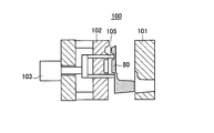
- FIG. 11 is a cross-sectional view of the die casting apparatus conceptually showing the state at the time of release.
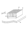
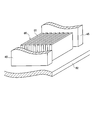
- the casting product mentioned here is a cooling fin shown in FIG.
- the cast product 80 is obtained by integrating a fin portion 81 in which a plurality of thin plates are erected in parallel and a flat plate portion 82 in which the fin portions 81 are orthogonal to each other.
- FIG. 11 is a view showing a side surface direction (X direction) in which the casting product 80 is manufactured and the fin portions 81 are arranged.
- the hydraulic cylinder 103 is extended and the cast product 80 is forcibly released from the movable mold 102 by the push pin 105.
- Patent Document 1 discloses a die-casting apparatus in which a nest is incorporated in a movable mold for fin molding and includes fluid supply means for supplying a liquid such as water or machine oil at a high pressure. According to this, after the molten metal solidifies, the insert is retracted to create a space between the product cooling fins, and the liquid is supplied and pressure is applied to the extrusion pin to perform the extrusion load simultaneously. Is made smaller.
- the die casting apparatus of the same document needs to be provided with a fluid supply means and the like, and the structure is complicated, and since a liquid is used, handling is troublesome.
- the present invention has an object to provide a die casting apparatus and a casting product releasing method that make it easy to release a cast product in order to solve such a problem.
- a die casting apparatus includes a fixed mold and a movable mold that form a cavity for molding a cast product, and forms a convex portion of the cast product in the movable main mold of the movable mold.
- the movable mold is provided so as to be slidable, and the movable mold includes a product pushing means for releasing the cast product from the movable main mold, and the insert in the mold release direction of the cast product.
- Nest moving means for moving, and convex release means for releasing the convex portion from the insert, and operating the product pushing means, the nested moving means, and the convex release means.
- the convex part releasing means of the die casting apparatus is an extruding means for extruding the cast product in the mold releasing direction in the vicinity of the convex part, and the extruding means extrudes the cast product to thereby provide the second mold release. It is preferable to perform the process.
- the push-out means is inserted into the both sides of the upright plate in the linear direction.
- the control means performs the second mold releasing step by alternately pushing one side of the push-out means sandwiching the insert.
- the insert moving means and the pushing means of the die casting apparatus can independently expand and contract the operating rod connected to the insert and the push pin pressed near the convex portion. It is preferable that the unit is configured integrally with a hydraulic unit.
- the insert moving means and the convex part releasing means of the die casting apparatus are independent of an operating rod connected to the insert and a plate-like extrusion block pressed near the convex part. It is preferable that the hydraulic unit be integrally formed by a hydraulic unit that can be expanded and contracted.
- the product extruding means of the die casting apparatus is such that a plurality of extruding pins or extruding blocks are fixed to an extruding plate, and the extruding plate is moved by a hydraulic cylinder, and the control means includes the hydraulic unit and the hydraulic cylinder It is preferable to be a hydraulic control means for controlling the driving of the motor.
- the die-casting apparatus is constituted by a divided block in which the insert is divided into a plurality of pieces, and the convex part releasing means moves the divided blocks of the insert in the release direction of the cast product. And a casting product extruded or supported by the extrusion means in the second mold release step.
- the casting product is extruded by the extrusion means in the mold release direction in the vicinity of the convex portion. It is preferable that the movement of each of the divided blocks that move relative to the releasable direction by the nest moving means is performed stepwise with respect to the convex portion.
- the divided block is divided into a plurality of portions in the linear direction of the upright plate. Preferably there is.
- the insert moving means and the pushing means of the die casting apparatus are each independently extended and retracted by operating rods connected to the respective divided blocks of the insert and push pins pressed near the convex portions. It is preferable that the hydraulic unit can be integrally formed.
- the insert moving means and the pushing means of the die casting apparatus have an operating rod connected to each divided block of the insert and a plate-like push block pressed near the convex portion, respectively. It is preferable that the unit is integrally formed by a hydraulic unit that can be expanded and contracted independently.
- the product extruding means of the die casting apparatus is such that a plurality of extruding pins or extruding blocks are fixed to an extruding plate, and the extruding plate is moved by a hydraulic cylinder, and the control means includes the hydraulic unit and the hydraulic cylinder It is preferable to be a hydraulic control means for controlling the driving of the motor.
- the convex part release means of the die casting apparatus is a grip means for moving the cast product in a gripped state, and the grip means moves the cast product in a predetermined direction to perform the second release step. It is preferable to do it.
- the gripping means pulls the cast product in a linear direction of the upright plates. It is preferable that the second mold releasing step is performed by moving the first step.
- a method for releasing a cast product wherein a die casting apparatus for forming a cast product having a convex portion is separated from a fixed mold and the mold is opened.
- the mold for forming the convex portion is moved according to the cast product, so that the portion other than the convex portion of the cast product is movable to constitute the movable mold. It has the 1st mold release process which releases from a main mold
- the second release step is performed in the linear direction of the upright plates. It is preferable that extrusion means arranged with the inserts interposed between the both side positions are used, and the cast product is extruded in the mold release direction by alternately operating one side in the linear direction.
- the second releasing step of the casting product releasing method uses the nest constituted by a plurality of divided blocks and moves the divided blocks stepwise to form the convex portion. It is preferable that the mold is released for each divided block.
- the second releasing step of the casting product releasing method uses a gripping means for moving the casting product while gripping the casting product, and the gripping means moves the casting product in a predetermined direction. Preferably there is.
- the second release step includes the gripping means having the convex shape. It is preferable that the cast product is drawn in the linear direction of the portion.
- the convex part having a high mold release resistance is not released, and only the convex part is released in the second mold release process.
- the resistance in each step is reduced, and the cast product can be easily released from the whole.
- the resistance to the said product extrusion means and convex part mold release means which mold-release a cast product at each process becomes small, and those breakage can be prevented.
- the resistance at the time of releasing the convex portion in the second mold releasing step is reduced, the stress applied to the boundary portion between the convex portion and the peripheral portion of the cast product can be reduced, and the casting Product damage can be prevented.
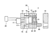
- FIG. 1 is a cross-sectional view conceptually showing the die casting apparatus of the first embodiment, showing a state where the mold is opened after casting.
- This die casting apparatus 1 is for producing a cast product 80 shown in FIG. 12, that is, a cooling fin, as in the conventional example.
- the die casting apparatus 1 includes a fixed mold 10 and a movable mold 20, and the movable mold 20 can be moved by an actuator shown in the figure, and the mold can be opened or clamped with respect to the fixed mold 10.
- the movable mold 20 is configured by coupling a movable main mold 12 to a base 14.
- An extrusion plate 15 is disposed between the movable main mold 12 and the base 14, and a plurality of extrusion pins 16 passing through the movable main mold 12 are fixed to the extrusion plate 15.
- a hydraulic cylinder 17 is fixed to the base 14, and an extrusion rod 171 passes through the base 14 and is coupled to the extrusion plate 15. Therefore, in the movable mold 20, the extrusion pin 16 is protruded by the hydraulic cylinder 17, and the cast product 80 is released.
- the insert 21 is a block formed in a shape reverse to that of the fin portion 81 (see FIG. 12) of the cast product 80.
- the movable mold 20 is provided with a hydraulic unit 22, and the hydraulic unit 22 includes an operating rod 23 connected to the insert 21 and extrusion pins 25 and 26 for releasing the cast product 80.
- a plurality of rods and pins can be extended and contracted independently. Therefore, the insert 21 can be slid with respect to the movable main mold 12 by the hydraulic unit 22.
- the die casting apparatus 1 uses the extrusion pins 25 and 26 in addition to the extrusion pin 16 to release the cast product 80 from the movable main mold 12.
- the extrusion pins 25 and 26 are arranged on both sides of the fin portion 81 in the longitudinal direction of the fin (Y direction shown in FIG. 12).
- five extrusion pins 25 are provided on one side.
- five extruding pins 26 are provided on the opposite side of the fin portion 81.
- a plurality of push pins 16 are arranged at predetermined positions farther from the fin portion 81 than the push pins 25 and 26.
- the die casting apparatus 1 is provided with a hydraulic control device 28 that controls the hydraulic cylinder 17 and the hydraulic unit 22.
- FIG. 1 are views showing the mold release process by the die casting apparatus 1 in a stepwise manner, and showing the post process of FIG.
- the die casting apparatus 1 molten metal is injected into a cavity formed by overlapping the fixed mold 10 and the movable mold 20, and the molten metal is solidified to form a cast product 80.
- the movable mold 20 is separated from the fixed mold 10 and the mold is opened as shown in FIG.
- the cast product 80 is pushed to the movable mold 20 side by an extrusion pin provided on the fixed mold 10. Therefore, as shown in FIG. 1, the cast product 80 is separated from the fixed mold 10 and is fitted to the movable mold 20 side.
- the release is divided into two steps, a first release step and a second release step.
- the extrusion pin 16 pushes the cast product 80 by the extension operation of the hydraulic cylinder 17 to release it from the movable main mold 12.
- the operating rod 23 extends by the same stroke as the hydraulic cylinder 17, and the insert 21 moves along with the cast product 80 pushed out by the push pin 16. Therefore, in this first mold release step, the cast product 80 is detached from the movable main mold 12, but the fin portion 81 is still fitted in the insert 21.
- the hydraulic unit 22 is operated, and the extrusion pins 25 and 26 are extended and pressed against the cast product 80.
- the insert 21 remains stationary. Therefore, the casting product 80 extruded in the mold release direction by the push pins 25 and 26 has its fin portion 81 removed from the insert 21 and the entire mold release is completed.
- a robot arm (not shown) follows the cast product 80, and the cast product 80 released from the mold is gripped by the robot arm so as not to fall after the mold release and transported to the next process. .
- the fin portion 81 having a large mold release resistance is not released and the resistance applied to the push pin 16 is reduced. Can do. Further, since the fin portion 81 is only released in the second releasing step, the resistance applied to the push pins 25 and 26 can be reduced. Therefore, since the resistance in each step is reduced, the push pin 16 and the push pins 25 and 26 can be prevented from being bent or bent. Further, since the resistance applied to the push pins 25 and 26 is reduced, the stress applied to the corner 85 at the boundary between the fin portion 81 where the stress is concentrated and the flat plate portion 82 is reduced, thereby preventing damage at the time of mold release. can do.
- FIG. 4 and 5 are views showing another second mold release step performed in place of the method shown in FIG.
- the hydraulic cylinder 17 is contracted, and the push pin 16 is pulled back into the movable main die 12 via the push plate 15 to leave the cast product 80.
- the hydraulic unit 22 extends and contracts the extrusion pins 25 and 26 separately while keeping the stroke of the operating rod 23 as it is.
- the extrusion pin 25 located on one side of the fin portion 81 is stretched and pressed against the cast product 80, and then the extrusion pin 25 is shrunk as shown in FIG. While being separated from the cast product 80, the extrusion pin 26 is extended and pressed against the cast product 80.
- the fin part 81 is released from the insert 21 by the method of alternately shifting the longitudinal ends of the fins.
- the force of each pin acts in a direction with an angle from the mold release direction, and the insert 21 and the fin portion 81 Since the force in the shear direction increases, it becomes easy to release. Furthermore, since a force is applied in an oblique direction, the gap between the insert 21 and the fin portion 81 becomes larger, and the frictional force between them can be reduced.
- the resistance applied to the push pins 25 and 26 is reduced, and the push pins 16 and the push pins 25 and 26 can be prevented from being bent or bent. Further, the stress applied to the corner 85 of the cast product 80 where the stress is concentrated is reduced, and breakage at the time of mold release can be prevented. And in the die-casting apparatus 1 of the present embodiment, since the above-mentioned effects can be achieved by a conventionally used hydraulic mechanism without a special structure, it can be achieved without cost, The device itself is easy to handle. Moreover, in the die-casting apparatus 1, since the extrusion pins 16, 25, and 26 do not directly push the fin portion 81, a thin fin can be manufactured, and the fin is not deformed at the time of mold release.
- the push pin 25 is shrunk, but the push pin 26 may be stretched in the stretched state.
- the extending operation of the extrusion pins 25 and 26 performed alternately may be repeated, for example, in increments of 0.1 mm, or may be synchronized from the middle as in the method shown in FIG.
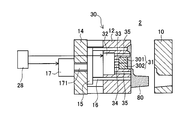
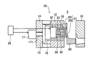
- FIG. 6 is a cross-sectional view conceptually showing the die casting apparatus of the second embodiment, showing a state where the mold is opened after casting.
- This die casting apparatus 2 is also for producing a cast product 80 shown in FIG. 12, that is, a cooling fin. And since it has the same structure as the die-casting apparatus 1 of 1st Embodiment, the same code
- the die casting apparatus 2 includes a fixed mold 10 and a movable mold 30, and the movable mold 30 is provided with a base 14 fixed to a movable main mold 12 and an extrusion pin 16 that is expanded and contracted by a hydraulic cylinder 17.
- a nest 31 divided into the movable main mold 12 is provided and can be moved by a hydraulic unit 32.
- the insert 31 is composed of a first block 301 and a second block 302, which are connected to the operating rods 33 and 34, respectively, to enable independent movement.
- the first and second blocks 301 and 302 are divided into two in the longitudinal direction of the fin, the direction of division may be a direction orthogonal to the fin, and the number of divisions is two or more. May be.
- the hydraulic unit 32 is also provided with an extrusion pin 35.
- the extrusion pins 35 correspond to the extrusion pins 25 and 26 shown in FIG. 13, and a plurality of extrusion pins 35 are arranged on both sides of the fin portion 81 in the longitudinal direction.
- a plurality of push pins 16 are provided at predetermined positions farther from the fin portion 81 than the push pins 35.
- the hydraulic cylinder 17 and the hydraulic unit 32 are connected to a hydraulic control device 28 that controls expansion and contraction of the push pins 16 and 35 and the operating rods 33 and 34.
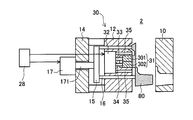
- FIG. 7 to FIG. 9 are diagrams showing the mold release process by the die casting apparatus 2 step by step, and show the post process of FIG.
- the die casting apparatus 2 molten metal is injected into a cavity formed by the fixed mold 10 and the movable mold 30, and the molten metal is solidified to form a cast product 80.
- mold opening is performed by moving the movable mold 30 from the fixed mold 10.
- the cast product 80 is fitted away from the fixed mold 10 and on the movable mold 30 side.
- the first release process of the cast product 80 is performed for releasing from the movable mold 30.
- the extrusion pin 16 pushes out the cast product 80 by the extension operation of the hydraulic cylinder 17 to release it from the movable main die 12.
- the operating rods 33 and 34 are extended by the same stroke as that of the hydraulic cylinder 17, and the insert 31 moves along with the movement of the cast product 80 pushed out to the extrusion pin 16. Therefore, the fin portion 81 of the cast product 80 is still fitted in the insert 31.
- the 2nd mold release process which removes the fin part 81 is performed.
- the extrusion pin 35 extends and the cast product 80 is pushed and moved. At that time, the stroke of the operating rod 33 is not changed, only the other operating rod 34 is extended, and the second block 302 is moved in accordance with the movement of the cast product 80 by the push pin 35. Thereby, in the fin part 81, the mold release by the 1st block 301 is performed previously among the inserts 31. FIG. Thereafter, as shown in FIG. 9, the extrusion pin 35 is further extended to move the cast product 80, but this time, the stroke of the operating rod 34 is left as it is. Thereby, the fin part 81 of the cast product 80 is detached from the second block 302 of the insert 31, and the entire mold release is completed. The released cast product 80 is gripped by a robot arm (not shown) so as not to fall, and is transferred to the next process.
- the extrusion pin 35 in this method functions as a member that extrudes the cast product 80 in the first mold release process and releases it from the movable main mold 12, and in the second mold release process, the stroke is left as it is. Functions as a support for 80.
- the insert 31 moves in the mold release direction in the first mold release process, and the fin portion 81 is not released, and only the fin part 81 is released in the second mold release process. Since it was made to do, the mold release resistance in each process can be made small. And the bending and bending can be prevented by making resistance at the time of mold release with respect to the extrusion pins 16 and 35 small.
- the mold release is performed stepwise by the divided nest 31, so that the mold release resistance for each block is reduced. Therefore, the stress applied to the corner portion 85 at the boundary between the fin portion 81 and the flat plate portion 82 where the stress is concentrated is reduced, and breakage at the time of mold release can be prevented. Further, in the die casting apparatus 2, since the extrusion pin does not directly push the fin portion 81, a thin fin can be manufactured, and the fin is not deformed.
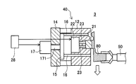
- FIG. 10 is a cross-sectional view conceptually showing the die casting apparatus of the third embodiment, and is a view showing a step of releasing the cast product from the movable mold.
- This die casting apparatus 3 is also for producing a cast product 80 shown in FIG. 12, that is, a cooling fin. And since this die-casting apparatus 3 also has the same structure as the die-casting apparatus 1 of 1st Embodiment, it attaches
- the die casting apparatus 3 includes a movable mold 40 and a fixed mold (not shown).
- the movable mold 40 is provided with a movable main mold 12 fixed to a base 14 and an extrusion pin 16 that is expanded and contracted by a hydraulic cylinder 17.
- the movable main mold 12 is provided with a slidable insert 21 and is connected to an operating rod 23 of a hydraulic unit 22.
- this die casting apparatus 3 is configured to perform stepwise release by the extrusion pin 16 and release by a robot arm that holds the cast product 80.
- the drawing shows the hand portion of the robot arm 50, which is used to grip the cast product 80 to prevent it from falling and to transport the cast product 80 to the next process.
- the cast product 80 is released as follows. First, after the movable mold 40 is separated from the fixed mold and the mold is opened, the first mold release process of the cast product 80 is performed in the movable mold 40.
- FIG. 10 shows a stage in which the first release process is finished and the process proceeds to the next second release process.
- the extrusion pin 16 extends through the extrusion plate 15 by the extension operation of the hydraulic cylinder 17, and the cast product 80 is pushed out of the movable main die 12 as shown in FIG.
- the operating rod 23 extends by the same stroke as that of the hydraulic cylinder 17, and the insert 21 moves in the mold release direction along with the cast product 80 pushed out to the extrusion pin 16.
- the fin portion 81 of the cast product 80 is still fitted in the insert 21, the fin portion 81 is released in the next second release step.
- the fin portion 81 is pulled out by the robot arm 50.
- the robot arm 50 moves the cast product 80 along the longitudinal direction of the fin. Thereby, the fin part 81 of the cast product 80 comes off from the insert 21, and the whole mold release is completed.
- the insert 21 moves out of the mold in the first mold releasing step, the fin portion 81 is not released, and only the fin portion 81 is released in the second mold releasing step. Since it molds, the mold release resistance in each process can be made small. Therefore, by reducing the resistance at the time of releasing from the extrusion pin 16, it is possible to prevent the bending or bending.
- the casting product 80 is moved in the longitudinal direction of the fin in the second mold releasing step, the stress applied to the corner portion 85 at the boundary between the fin portion 81 where the stress is concentrated and the flat plate portion 82 is reduced. Breakage during molding can be prevented. Furthermore, since the extrusion pin does not directly push the fin portion 81, a thin fin can be manufactured and the fin is not deformed.
- the die-casting apparatus which concerns on this invention, and the mold release method of cast product was described, this invention is not limited to the said embodiment, In the range which does not deviate from the meaning of this invention, it is various. Needless to say, improvements and modifications are possible.
- the fin portion 81 is released using the extrusion pins 25 and 26 and the extrusion pin 35, but the extrusion pins 25 and 26 and the extrusion pin 35 are used.
- the plate-like extrusion block 45 shown in FIG. 14 may be configured to be taken in and out by a hydraulic unit.
- casting products manufactured by the die casting apparatus are not limited to cooling fins, and even cooling fins are not limited to straight fins depending on the embodiment, and are for example meandering fins and pin fins. Also good.
- the strokes of the extrusion pins 25 and 26 may be managed while detecting the resistance by the load cell.
- the robot is provided with the extrusion pins 25 and 26 as in the first embodiment and the fin portion 81 is shifted. You may make it pull out with the arm 50. FIG. Moreover, you may make it add the means which gives vibration to a nest
Landscapes
- Engineering & Computer Science (AREA)
- Mechanical Engineering (AREA)
- Molds, Cores, And Manufacturing Methods Thereof (AREA)
- Moulds For Moulding Plastics Or The Like (AREA)
Abstract
Description
10 固定型
20 可動型
12 可動主型
15 押出板
16 押出ピン
17 油圧シリンダ
21 入子
22 油圧ユニット
23 作動ロッド
25,26 押出ピン
28 油圧制御装置
80 鋳造製品
81 フィン部分
次に、本発明に係るダイカスト鋳造装置の第2実施形態について説明する。図6は、第2実施形態のダイカスト鋳造装置を概念的に示した断面図であり、鋳造後の型開きした状態を示している。このダイカスト鋳造装置2も、図12に示す鋳造製品80すなわち冷却フィンを製造するためのものである。そして、第1実施形態のダイカスト鋳造装置1と同じ構成を有するため、同じ構成には同じ符号を付して説明する。
次に、本発明に係るダイカスト鋳造装置の第3実施形態について説明する。図10は、第3実施形態のダイカスト鋳造装置を概念的に示した断面図であり、鋳造製品を可動型から離型させる工程を示した図である。このダイカスト鋳造装置3も、図12に示す鋳造製品80すなわち冷却フィンを製造するためのものである。そして、このダイカスト鋳造装置3も第1実施形態のダイカスト鋳造装置1と同じ構成を有するため、同じ構成には同じ符号を付して説明する。
Claims (18)
- 鋳造製品を成形するためのキャビティを構成する固定型と可動型とを有し、前記可動型の可動主型内に前記鋳造製品の凸形状部分を成形する入子がスライド可能に設けられたものであるダイカスト鋳造装置において、
前記可動型は、前記鋳造製品を前記可動主型から離型させるための製品押出手段と、前記入子を前記鋳造製品の離型方向に移動させる入子移動手段と、前記凸形状部分を前記入子から離型させる凸部離型手段とを有し、
前記製品押出手段、前記入子移動手段および前記凸部離型手段の作動を制御する制御手段により、前記製品押出手段によって前記鋳造製品を前記可動主型から離型させるとともに、前記入子移動手段によって前記入子を前記鋳造製品に従って移動させる第1離型工程と、前記凸部離型手段によって前記凸形状部分を前記入子から離型させる第2離型工程とが実行されるものであることを特徴とするダイカスト鋳造装置。 - 請求項1に記載するダイカスト鋳造装置において、
前記凸部離型手段は、前記凸形状部分の近傍で前記鋳造製品を離型方向に押し出す押出手段であり、当該押出手段が前記鋳造製品を押し出すことにより前記第2離型工程を行うものであることを特徴とするダイカスト鋳造装置。 - 請求項2に記載するダイカスト鋳造装置において、
前記入子が直線状の起立板を複数並べた前記凸形状部分を成形するものである場合に、
前記押出手段は、前記起立板の直線方向の両側位置に前記入子を挟んで配置され、
前記制御手段は、前記押出手段のうち前記入子を挟んだ片側ずつを交互に押すことにより前記第2離型工程を行うものであることを特徴とするダイカスト鋳造装置。 - 請求項2又は請求項3に記載するダイカスト鋳造装置において、
前記入子移動手段および前記押出手段は、前記入子に連結された作動ロッドと、前記凸形状部分の近傍に押し当てられる押出ピンとを、各々独立して伸縮させることができる油圧ユニットによって一体に構成されたものであることを特徴とするダイカスト鋳造装置。 - 請求項1に記載するダイカスト鋳造装置において、
前記入子移動手段および前記凸部離型手段は、前記入子に連結された作動ロッドと、前記凸形状部分の近傍に押し当てられる板状の押出ブロックとを、各々独立して伸縮させることができる油圧ユニットによって一体に構成されたものであることを特徴とするダイカスト鋳造装置。 - 請求項4又は請求項5に記載するダイカスト鋳造装置において、
前記製品押出手段は、複数の押出ピンまたは押出ブロックが押出板に固定され、その押出板を油圧シリンダによって移動させるものであり、前記制御手段は、前記油圧ユニットおよび前記油圧シリンダを駆動制御する油圧制御手段であることを特徴とするダイカスト鋳造装置。 - 請求項1に記載するダイカスト鋳造装置において、
前記入子は、複数に分割された分割ブロックによって構成され、前記凸部離型手段は、前記入子の各分割ブロックを前記鋳造製品の離型方向に移動させる入子移動手段および、前記凸形状部分の近傍で前記鋳造製品を離型方向に押し出す押出手段によって構成されたものであり、
前記第2離型工程では、前記押出手段によって押し出され又は支持された前記鋳造製品の凸形状部分に対して、前記入子移動手段によって反離型方向へ相対的に移動する前記各分割ブロックの当該移動が段階的に行われるようにしたものであることを特徴とするダイカスト鋳造装置。 - 請求項7に記載するダイカスト鋳造装置において、
前記入子が直線状の起立板を複数並べた前記凸形状部分を成形するものである場合に、前記分割ブロックは、前記起立板の直線方向に複数分割されたものであることを特徴とするダイカスト鋳造装置。 - 請求項7に記載するダイカスト鋳造装置において、
前記入子移動手段及び前記押出手段は、前記入子の各分割ブロックに連結された作動ロッドと、前記凸形状部分の近傍に押し当てられる押出ピンとを、各々独立して伸縮させることができる油圧ユニットによって一体に構成されたものであることを特徴とするダイカスト鋳造装置。 - 請求項7に記載するダイカスト鋳造装置において、
前記入子移動手段及び前記押出手段は、前記入子の各分割ブロックに連結された作動ロッドと、前記凸形状部分の近傍に押し当てられる板状の押出ブロックとを、各々独立して伸縮させることができる油圧ユニットによって一体に構成されたものであることを特徴とするダイカスト鋳造装置。 - 請求項9又は請求項10に記載するダイカスト鋳造装置において、
前記製品押出手段は、複数の押出ピンまたは押出ブロックが押出板に固定され、その押出板を油圧シリンダによって移動させるものであり、前記制御手段は、前記油圧ユニットおよび前記油圧シリンダを駆動制御する油圧制御手段であることを特徴とするダイカスト鋳造装置。 - 請求項1に記載するダイカスト鋳造装置において、
前記凸部離型手段は、前記鋳造製品を把持した状態で移動させる把持手段であり、当該把持手段が前記鋳造製品を所定方向に移動させることにより前記第2離型工程を行うものであることを特徴とするダイカスト鋳造装置。 - 請求項12に記載するダイカスト鋳造装置において、
前記入子が直線状の起立板を複数並べた前記凸形状部分を成形するものである場合に、前記把持手段は、前記起立板の直線方向に前記鋳造製品を引くことにより移動させて前記第2離型工程を行うものであることを特徴とするダイカスト鋳造装置。 - 凸形状部分を有する鋳造製品を成形するダイカスト鋳造装置について、固定型から可動型を離して型開きした後、その可動型から前記鋳造製品を離型させる鋳造製品の離型方法において、
前記凸形状部分を成形するための入子を前記鋳造製品に従って移動させることにより、前記鋳造製品のうち前記凸形状部分以外の部分を前記可動型を構成する可動主型から離型させる第1離型工程と、前記凸形状部分を前記入子から離型させる第2離型工程とを有することを特徴とする鋳造製品の離型方法。 - 請求項14に記載する鋳造製品の離型方法において、
前記入子が直線状の起立板を複数並べた前記凸形状部分を成形するものである場合に、
前記第2離型工程は、前記起立板の直線方向の両側位置に対応して前記入子を挟んで配置された押出手段使用し、前記直線方向の片側ずつ交互に作動させて離型方向に前記鋳造製品を押し出すようにしたものであることを特徴とする鋳造製品の離型方法。 - 請求項14に記載する鋳造製品の離型方法において、
前記第2離型工程は、複数に分割された分割ブロックによって構成された前記入子を使用し、前記各分割ブロックを段階的に移動させることにより前記凸形状部分を各分割ブロック毎に離型させるようにしたものであることを特徴とする鋳造製品の離型方法。 - 請求項14に記載する鋳造製品の離型方法において、
前記第2離型工程は、前記鋳造製品を把持した状態で移動させる把持手段を使用し、その把持手段が前記鋳造製品を所定方向に移動させるようにしたものであることを特徴とする鋳造製品の離型方法。 - 請求項17に記載する鋳造製品の離型方法において、
前記入子が直線状の起立板を複数並べた前記凸形状部分を成形するものである場合に、
前記第2離型工程は、前記把持手段が前記凸形状部分の直線方向に前記鋳造製品を引くようにしたものであることを特徴とする鋳造製品の離型方法。
Priority Applications (6)
| Application Number | Priority Date | Filing Date | Title |
|---|---|---|---|
| JP2011550161A JPWO2012120601A1 (ja) | 2011-03-04 | 2011-03-04 | ダイカスト鋳造装置及び鋳造製品の離型方法 |
| KR1020137023303A KR20130122672A (ko) | 2011-03-04 | 2011-03-04 | 다이캐스트 주조 장치 및 주조 제품의 이형 방법 |
| US14/002,954 US20130340968A1 (en) | 2011-03-04 | 2011-03-04 | Die cast casting apparatus and method for releasing casting from mold |
| CN2011800689659A CN103402674A (zh) | 2011-03-04 | 2011-03-04 | 压铸铸造装置以及铸造产品的脱模方法 |
| PCT/JP2011/055125 WO2012120601A1 (ja) | 2011-03-04 | 2011-03-04 | ダイカスト鋳造装置及び鋳造製品の離型方法 |
| EP11860605.2A EP2682205A1 (en) | 2011-03-04 | 2011-03-04 | Die cast casting apparatus and method for releasing casting from mold |
Applications Claiming Priority (1)
| Application Number | Priority Date | Filing Date | Title |
|---|---|---|---|
| PCT/JP2011/055125 WO2012120601A1 (ja) | 2011-03-04 | 2011-03-04 | ダイカスト鋳造装置及び鋳造製品の離型方法 |
Publications (1)
| Publication Number | Publication Date |
|---|---|
| WO2012120601A1 true WO2012120601A1 (ja) | 2012-09-13 |
Family
ID=46797611
Family Applications (1)
| Application Number | Title | Priority Date | Filing Date |
|---|---|---|---|
| PCT/JP2011/055125 Ceased WO2012120601A1 (ja) | 2011-03-04 | 2011-03-04 | ダイカスト鋳造装置及び鋳造製品の離型方法 |
Country Status (6)
| Country | Link |
|---|---|
| US (1) | US20130340968A1 (ja) |
| EP (1) | EP2682205A1 (ja) |
| JP (1) | JPWO2012120601A1 (ja) |
| KR (1) | KR20130122672A (ja) |
| CN (1) | CN103402674A (ja) |
| WO (1) | WO2012120601A1 (ja) |
Cited By (3)
| Publication number | Priority date | Publication date | Assignee | Title |
|---|---|---|---|---|
| CN110802213A (zh) * | 2019-11-29 | 2020-02-18 | 浙江拓卡斯科技股份有限公司 | 一种新能源电动汽车控制器壳体铸造模具及其工作方法 |
| CN116100767A (zh) * | 2022-11-30 | 2023-05-12 | 苏州多维精密机电有限公司 | 一种模具抽芯机构 |
| CN118617645A (zh) * | 2024-08-14 | 2024-09-10 | 宁波富声达电机有限公司 | 一种基于脱模机全流程控制方法、系统、存储介质及终端 |
Families Citing this family (14)
| Publication number | Priority date | Publication date | Assignee | Title |
|---|---|---|---|---|
| US9102373B2 (en) * | 2013-11-27 | 2015-08-11 | GM Global Technology Operations LLC | Hinge pillar assembly having an inner retainer panel, and method of manufacturing the same |
| EP3237130A1 (en) * | 2014-12-22 | 2017-11-01 | O.M.C. S.r.l. | Mould for elements of bimetal radiators and related method |
| CN108339959A (zh) * | 2016-12-27 | 2018-07-31 | 李永宏 | 一种轴套零件成形模具 |
| CN109049545B (zh) * | 2018-06-12 | 2023-09-01 | 临海伟星新型建材有限公司 | 一种用于u型弯管件注塑成型的模具 |
| CN113634740A (zh) * | 2021-08-05 | 2021-11-12 | 盐城市悦丰模具有限公司 | 一种调节阀模配件铸造模具 |
| CN113828752B (zh) * | 2021-08-25 | 2023-01-24 | 深圳市品成金属制品有限公司 | 一种二次顶出压铸模具 |
| CN114951594B (zh) * | 2022-06-20 | 2023-12-12 | 广德垣鑫数控重机有限公司 | 一种快速脱模的工件铸造方法 |
| CN115383093A (zh) * | 2022-08-31 | 2022-11-25 | 含山县勇宇机械制造有限公司 | 一种液压件铸造用铸造模具 |
| CN116944310A (zh) * | 2023-07-27 | 2023-10-27 | 福建圣力智能工业科技股份有限公司 | 一种采用八边形连铸坯进行无头轧制的生产线 |
| KR20250037099A (ko) * | 2023-09-08 | 2025-03-17 | 현대자동차주식회사 | 다이 캐스팅용 이젝팅 장치 |
| CN118371696B (zh) * | 2024-06-24 | 2024-11-01 | 山东宇众汽车科技有限公司 | 一种铸件脱模连续输送装置 |
| CN118404029B (zh) * | 2024-07-03 | 2024-09-20 | 广东鸿图(南通)模具有限公司 | 一种具有推板结构的压铸铝合金模具 |
| CN118493779B (zh) * | 2024-07-12 | 2024-11-22 | 金永和精工制造股份有限公司 | 一种深内腔蜡件脱模装置 |
| CN121360800A (zh) * | 2025-12-22 | 2026-01-20 | 宁波众鑫里美科技有限公司 | 一种用于制作出气室的模具系统及方法 |
Citations (6)
| Publication number | Priority date | Publication date | Assignee | Title |
|---|---|---|---|---|
| JPS61205652U (ja) * | 1985-06-15 | 1986-12-25 | ||
| JPH04176621A (ja) * | 1990-11-13 | 1992-06-24 | Nissan Motor Co Ltd | 射出成形金型のエジェクタプレートのロック装置 |
| JPH0526332U (ja) * | 1991-09-09 | 1993-04-06 | 豊田紡織株式会社 | 射出成形用金型 |
| JPH08300132A (ja) | 1995-03-06 | 1996-11-19 | Toyota Motor Corp | 鋳造方法及び鋳造装置 |
| JPH08300425A (ja) * | 1995-05-11 | 1996-11-19 | Fanuc Ltd | 成形品取出装置 |
| JPH09300058A (ja) * | 1996-05-14 | 1997-11-25 | Ahresty Corp | ダイカスト用金型 |
Family Cites Families (5)
| Publication number | Priority date | Publication date | Assignee | Title |
|---|---|---|---|---|
| JPS62197261A (ja) * | 1986-02-25 | 1987-08-31 | Toyo Kikai Kinzoku Kk | ダイカストマシンの製品押出方法 |
| US6955210B2 (en) * | 2001-12-26 | 2005-10-18 | Toyota Jidosha Kabushiki Kaisha | Molding die and die changing method of the same |
| JP2006256285A (ja) * | 2005-03-18 | 2006-09-28 | Citizen Electronics Co Ltd | 射出成形金型 |
| JP2007083273A (ja) * | 2005-09-21 | 2007-04-05 | Honda Motor Co Ltd | 鋳造用金型装置 |
| JP2009056503A (ja) * | 2007-09-03 | 2009-03-19 | Toyota Motor Corp | 成形金型および成形方法 |
-
2011
- 2011-03-04 CN CN2011800689659A patent/CN103402674A/zh active Pending
- 2011-03-04 KR KR1020137023303A patent/KR20130122672A/ko not_active Ceased
- 2011-03-04 US US14/002,954 patent/US20130340968A1/en not_active Abandoned
- 2011-03-04 JP JP2011550161A patent/JPWO2012120601A1/ja active Pending
- 2011-03-04 EP EP11860605.2A patent/EP2682205A1/en not_active Withdrawn
- 2011-03-04 WO PCT/JP2011/055125 patent/WO2012120601A1/ja not_active Ceased
Patent Citations (6)
| Publication number | Priority date | Publication date | Assignee | Title |
|---|---|---|---|---|
| JPS61205652U (ja) * | 1985-06-15 | 1986-12-25 | ||
| JPH04176621A (ja) * | 1990-11-13 | 1992-06-24 | Nissan Motor Co Ltd | 射出成形金型のエジェクタプレートのロック装置 |
| JPH0526332U (ja) * | 1991-09-09 | 1993-04-06 | 豊田紡織株式会社 | 射出成形用金型 |
| JPH08300132A (ja) | 1995-03-06 | 1996-11-19 | Toyota Motor Corp | 鋳造方法及び鋳造装置 |
| JPH08300425A (ja) * | 1995-05-11 | 1996-11-19 | Fanuc Ltd | 成形品取出装置 |
| JPH09300058A (ja) * | 1996-05-14 | 1997-11-25 | Ahresty Corp | ダイカスト用金型 |
Cited By (3)
| Publication number | Priority date | Publication date | Assignee | Title |
|---|---|---|---|---|
| CN110802213A (zh) * | 2019-11-29 | 2020-02-18 | 浙江拓卡斯科技股份有限公司 | 一种新能源电动汽车控制器壳体铸造模具及其工作方法 |
| CN116100767A (zh) * | 2022-11-30 | 2023-05-12 | 苏州多维精密机电有限公司 | 一种模具抽芯机构 |
| CN118617645A (zh) * | 2024-08-14 | 2024-09-10 | 宁波富声达电机有限公司 | 一种基于脱模机全流程控制方法、系统、存储介质及终端 |
Also Published As
| Publication number | Publication date |
|---|---|
| CN103402674A (zh) | 2013-11-20 |
| JPWO2012120601A1 (ja) | 2014-07-07 |
| US20130340968A1 (en) | 2013-12-26 |
| EP2682205A1 (en) | 2014-01-08 |
| KR20130122672A (ko) | 2013-11-07 |
Similar Documents
| Publication | Publication Date | Title |
|---|---|---|
| JPWO2012120601A1 (ja) | ダイカスト鋳造装置及び鋳造製品の離型方法 | |
| CN106103058B (zh) | 用于制造薄壁的塑料型材的方法和装置 | |
| CN107949445B (zh) | 成形装置及成形制品的制造方法 | |
| EP4091738B1 (en) | Apparatus and method for forming material | |
| JP2011125888A (ja) | 油圧プレス装置 | |
| CN202411308U (zh) | 一种分离式闭塞锻造装置 | |
| ITUB20154863A1 (it) | Apparecchiatura per la produzione di pezzi meccanici di ridotte dimensioni | |
| JP2003112341A (ja) | 射出成形装置 | |
| JP5440680B2 (ja) | ハイドロフォーム装置 | |
| JP5550935B2 (ja) | 金型構造と鋳造方法 | |
| CN219727089U (zh) | 可进行推料装配的注塑模具 | |
| CN113618046A (zh) | 一种5g通讯件模具 | |
| CN113649545A (zh) | 一种过渡垫板成型装置以及成型方法 | |
| JP3847293B2 (ja) | 鋳造用金型装置及び鋳造方法 | |
| JP2009214116A (ja) | 鋳造金型及び鋳造方法 | |
| CN223099824U (zh) | 一种注塑模具多层套筒抽芯机构 | |
| CN112659440A (zh) | Smc油底壳的成型模具 | |
| JP2014018837A (ja) | ダイカストマシンの押出し機構 | |
| CN216028005U (zh) | 合金压铸机 | |
| CN213082039U (zh) | 一种照明灯模具结构 | |
| JPH08276259A (ja) | 成形装置および成形方法 | |
| JP5239505B2 (ja) | ハイドロフォーム加工方法 | |
| CN210115392U (zh) | 一种可自动脱模的铝合金挤压加工用模具 | |
| JP6090236B2 (ja) | 中子造型装置におけるスライドコアの引抜方法、スライドコアの引抜制御装置及び中子造型装置 | |
| JP4757833B2 (ja) | 金型装置,その装着方法及び成形装置 |
Legal Events
| Date | Code | Title | Description |
|---|---|---|---|
| ENP | Entry into the national phase |
Ref document number: 2011550161 Country of ref document: JP Kind code of ref document: A |
|
| 121 | Ep: the epo has been informed by wipo that ep was designated in this application |
Ref document number: 11860605 Country of ref document: EP Kind code of ref document: A1 |
|
| WWE | Wipo information: entry into national phase |
Ref document number: 2011860605 Country of ref document: EP |
|
| ENP | Entry into the national phase |
Ref document number: 20137023303 Country of ref document: KR Kind code of ref document: A |
|
| WWE | Wipo information: entry into national phase |
Ref document number: 14002954 Country of ref document: US |
|
| NENP | Non-entry into the national phase |
Ref country code: DE |