WO2012124386A1 - Vanne de commande - Google Patents
Vanne de commande Download PDFInfo
- Publication number
- WO2012124386A1 WO2012124386A1 PCT/JP2012/051777 JP2012051777W WO2012124386A1 WO 2012124386 A1 WO2012124386 A1 WO 2012124386A1 JP 2012051777 W JP2012051777 W JP 2012051777W WO 2012124386 A1 WO2012124386 A1 WO 2012124386A1
- Authority
- WO
- WIPO (PCT)
- Prior art keywords
- pilot
- pilot chamber
- spool
- signal pressure
- pressure passage
- Prior art date
- Legal status (The legal status is an assumption and is not a legal conclusion. Google has not performed a legal analysis and makes no representation as to the accuracy of the status listed.)
- Ceased
Links
Images

Classifications
-
- F—MECHANICAL ENGINEERING; LIGHTING; HEATING; WEAPONS; BLASTING
- F15—FLUID-PRESSURE ACTUATORS; HYDRAULICS OR PNEUMATICS IN GENERAL
- F15B—SYSTEMS ACTING BY MEANS OF FLUIDS IN GENERAL; FLUID-PRESSURE ACTUATORS, e.g. SERVOMOTORS; DETAILS OF FLUID-PRESSURE SYSTEMS, NOT OTHERWISE PROVIDED FOR
- F15B13/00—Details of servomotor systems ; Valves for servomotor systems
- F15B13/02—Fluid distribution or supply devices characterised by their adaptation to the control of servomotors
- F15B13/04—Fluid distribution or supply devices characterised by their adaptation to the control of servomotors for use with a single servomotor
- F15B13/0401—Valve members; Fluid interconnections therefor
- F15B13/0402—Valve members; Fluid interconnections therefor for linearly sliding valves, e.g. spool valves
-
- F—MECHANICAL ENGINEERING; LIGHTING; HEATING; WEAPONS; BLASTING
- F15—FLUID-PRESSURE ACTUATORS; HYDRAULICS OR PNEUMATICS IN GENERAL
- F15B—SYSTEMS ACTING BY MEANS OF FLUIDS IN GENERAL; FLUID-PRESSURE ACTUATORS, e.g. SERVOMOTORS; DETAILS OF FLUID-PRESSURE SYSTEMS, NOT OTHERWISE PROVIDED FOR
- F15B11/00—Servomotor systems without provision for follow-up action; Circuits therefor
-
- F—MECHANICAL ENGINEERING; LIGHTING; HEATING; WEAPONS; BLASTING
- F15—FLUID-PRESSURE ACTUATORS; HYDRAULICS OR PNEUMATICS IN GENERAL
- F15B—SYSTEMS ACTING BY MEANS OF FLUIDS IN GENERAL; FLUID-PRESSURE ACTUATORS, e.g. SERVOMOTORS; DETAILS OF FLUID-PRESSURE SYSTEMS, NOT OTHERWISE PROVIDED FOR
- F15B13/00—Details of servomotor systems ; Valves for servomotor systems
- F15B13/02—Fluid distribution or supply devices characterised by their adaptation to the control of servomotors
- F15B13/04—Fluid distribution or supply devices characterised by their adaptation to the control of servomotors for use with a single servomotor
- F15B13/042—Fluid distribution or supply devices characterised by their adaptation to the control of servomotors for use with a single servomotor operated by fluid pressure
-
- F—MECHANICAL ENGINEERING; LIGHTING; HEATING; WEAPONS; BLASTING
- F16—ENGINEERING ELEMENTS AND UNITS; GENERAL MEASURES FOR PRODUCING AND MAINTAINING EFFECTIVE FUNCTIONING OF MACHINES OR INSTALLATIONS; THERMAL INSULATION IN GENERAL
- F16K—VALVES; TAPS; COCKS; ACTUATING-FLOATS; DEVICES FOR VENTING OR AERATING
- F16K11/00—Multiple-way valves, e.g. mixing valves; Pipe fittings incorporating such valves
- F16K11/02—Multiple-way valves, e.g. mixing valves; Pipe fittings incorporating such valves with all movable sealing faces moving as one unit
- F16K11/06—Multiple-way valves, e.g. mixing valves; Pipe fittings incorporating such valves with all movable sealing faces moving as one unit comprising only sliding valves, i.e. sliding closure elements
- F16K11/065—Multiple-way valves, e.g. mixing valves; Pipe fittings incorporating such valves with all movable sealing faces moving as one unit comprising only sliding valves, i.e. sliding closure elements with linearly sliding closure members
- F16K11/07—Multiple-way valves, e.g. mixing valves; Pipe fittings incorporating such valves with all movable sealing faces moving as one unit comprising only sliding valves, i.e. sliding closure elements with linearly sliding closure members with cylindrical slides
-
- F—MECHANICAL ENGINEERING; LIGHTING; HEATING; WEAPONS; BLASTING
- F16—ENGINEERING ELEMENTS AND UNITS; GENERAL MEASURES FOR PRODUCING AND MAINTAINING EFFECTIVE FUNCTIONING OF MACHINES OR INSTALLATIONS; THERMAL INSULATION IN GENERAL
- F16K—VALVES; TAPS; COCKS; ACTUATING-FLOATS; DEVICES FOR VENTING OR AERATING
- F16K3/00—Gate valves or sliding valves, i.e. cut-off apparatus with closing members having a sliding movement along the seat for opening and closing
- F16K3/22—Gate valves or sliding valves, i.e. cut-off apparatus with closing members having a sliding movement along the seat for opening and closing with sealing faces shaped as surfaces of solids of revolution
- F16K3/24—Gate valves or sliding valves, i.e. cut-off apparatus with closing members having a sliding movement along the seat for opening and closing with sealing faces shaped as surfaces of solids of revolution with cylindrical valve members
- F16K3/26—Gate valves or sliding valves, i.e. cut-off apparatus with closing members having a sliding movement along the seat for opening and closing with sealing faces shaped as surfaces of solids of revolution with cylindrical valve members with fluid passages in the valve member
-
- F—MECHANICAL ENGINEERING; LIGHTING; HEATING; WEAPONS; BLASTING
- F16—ENGINEERING ELEMENTS AND UNITS; GENERAL MEASURES FOR PRODUCING AND MAINTAINING EFFECTIVE FUNCTIONING OF MACHINES OR INSTALLATIONS; THERMAL INSULATION IN GENERAL
- F16K—VALVES; TAPS; COCKS; ACTUATING-FLOATS; DEVICES FOR VENTING OR AERATING
- F16K31/00—Actuating devices; Operating means; Releasing devices
- F16K31/12—Actuating devices; Operating means; Releasing devices actuated by fluid
- F16K31/122—Actuating devices; Operating means; Releasing devices actuated by fluid the fluid acting on a piston
-
- Y—GENERAL TAGGING OF NEW TECHNOLOGICAL DEVELOPMENTS; GENERAL TAGGING OF CROSS-SECTIONAL TECHNOLOGIES SPANNING OVER SEVERAL SECTIONS OF THE IPC; TECHNICAL SUBJECTS COVERED BY FORMER USPC CROSS-REFERENCE ART COLLECTIONS [XRACs] AND DIGESTS
- Y10—TECHNICAL SUBJECTS COVERED BY FORMER USPC
- Y10T—TECHNICAL SUBJECTS COVERED BY FORMER US CLASSIFICATION
- Y10T137/00—Fluid handling
- Y10T137/7722—Line condition change responsive valves
- Y10T137/7758—Pilot or servo controlled
- Y10T137/7762—Fluid pressure type
-
- Y—GENERAL TAGGING OF NEW TECHNOLOGICAL DEVELOPMENTS; GENERAL TAGGING OF CROSS-SECTIONAL TECHNOLOGIES SPANNING OVER SEVERAL SECTIONS OF THE IPC; TECHNICAL SUBJECTS COVERED BY FORMER USPC CROSS-REFERENCE ART COLLECTIONS [XRACs] AND DIGESTS
- Y10—TECHNICAL SUBJECTS COVERED BY FORMER USPC
- Y10T—TECHNICAL SUBJECTS COVERED BY FORMER US CLASSIFICATION
- Y10T137/00—Fluid handling
- Y10T137/8593—Systems
- Y10T137/86493—Multi-way valve unit
- Y10T137/86574—Supply and exhaust
- Y10T137/86622—Motor-operated
- Y10T137/8663—Fluid motor
-
- Y—GENERAL TAGGING OF NEW TECHNOLOGICAL DEVELOPMENTS; GENERAL TAGGING OF CROSS-SECTIONAL TECHNOLOGIES SPANNING OVER SEVERAL SECTIONS OF THE IPC; TECHNICAL SUBJECTS COVERED BY FORMER USPC CROSS-REFERENCE ART COLLECTIONS [XRACs] AND DIGESTS
- Y10—TECHNICAL SUBJECTS COVERED BY FORMER USPC
- Y10T—TECHNICAL SUBJECTS COVERED BY FORMER US CLASSIFICATION
- Y10T137/00—Fluid handling
- Y10T137/8593—Systems
- Y10T137/86493—Multi-way valve unit
- Y10T137/86574—Supply and exhaust
- Y10T137/8667—Reciprocating valve
- Y10T137/86694—Piston valve
- Y10T137/86702—With internal flow passage
-
- Y—GENERAL TAGGING OF NEW TECHNOLOGICAL DEVELOPMENTS; GENERAL TAGGING OF CROSS-SECTIONAL TECHNOLOGIES SPANNING OVER SEVERAL SECTIONS OF THE IPC; TECHNICAL SUBJECTS COVERED BY FORMER USPC CROSS-REFERENCE ART COLLECTIONS [XRACs] AND DIGESTS
- Y10—TECHNICAL SUBJECTS COVERED BY FORMER USPC
- Y10T—TECHNICAL SUBJECTS COVERED BY FORMER US CLASSIFICATION
- Y10T137/00—Fluid handling
- Y10T137/8593—Systems
- Y10T137/86493—Multi-way valve unit
- Y10T137/86574—Supply and exhaust
- Y10T137/8667—Reciprocating valve
- Y10T137/86694—Piston valve
- Y10T137/8671—With annular passage [e.g., spool]
Definitions
- the present invention relates to a control valve that is switched by the action of pilot pressure and guides the pilot pressure to other equipment.
- FIG. 2 the one shown in FIG. 2 is conventionally known.
- a spool 2 is slidably incorporated in the valve body 1, and a spring force of a centering spring 3 is applied to the spool 2.
- Both ends of the spool 2 face the pilot chambers 4, 5, and the spool 2 is switched by the action of the pilot pressure guided to one of the pilot chambers 4, 5, and a pair of actuator ports 6 formed in the valve body 1 7 communicates with the pump, and the other communicates with the tank.
- the valve body 1 is formed with a signal pressure passage 8 that guides the pilot pressure in the pilot chamber 4 or 5 as the signal pressure of other equipment.
- the signal pressure passage 8 communicates with the pilot chamber 4 via a check valve 9.
- the check valve 9 allows only the flow of hydraulic oil from the pilot chamber 4 to the signal pressure passage 8.
- the pilot chamber 5 communicates with the signal pressure passage 8 through a communication hole 10 formed in the spool 2 and a check valve 11 provided in the communication hole 10.
- the check valve 11 allows only hydraulic fluid to flow from the pilot chamber 5 to the signal pressure passage 8.
- the spool 2 moves in the right direction in the figure against the spring force of the centering spring 3, the actuator port 7 communicates with the pump, and the actuator port 6 communicates with the tank.
- the pilot pressure guided to the pilot chamber 4 pushes the check valve 9 open, is guided to the signal pressure passage 8, and is guided from the signal pressure passage 8 to other devices.
- the spool 2 moves to the left in the figure against the spring of the centering spring 3, the actuator port 6 communicates with the pump, and the actuator port 7 communicates with the tank.
- the pilot pressure led to the pilot chamber 5 pushes the check valve 11 through the communication hole 10 and is led to the signal pressure passage 8, and is led from the signal pressure passage 8 to other devices.
- the actuator operated by the control valve is synchronized with other equipment.
- pilot chambers 4 and 5 communicate with each other through the signal pressure passage 8.
- pilot pressure is guided to one of the pilot chambers 4 and 5, the other pilot chamber communicates with a tank maintained at atmospheric pressure, so that both pilot chambers 4 and 5 communicate with each other through the signal pressure passage 8. If this happens, no pilot pressure will be generated in any of the pilot chambers 4 and 5.
- check valves 9 and 11 are provided.
- the signal pressure passage 8 is provided with two check valves 9 and 11. For this reason, the pressure in the signal pressure passage 8 may not be completely removed. As a result, other devices may malfunction.
- the present invention has been made in view of the above-described problems, and an object thereof is to prevent malfunction of other devices when the spool is returned to the neutral position.
- the first pilot chamber includes a spool slidably incorporated in the valve body, and a first pilot chamber and a second pilot chamber disposed facing both ends of the spool.
- a control valve in which the spool moves by the action of a pilot pressure guided to one of the chamber and the second pilot chamber, and is formed in the valve body, and is a pilot in the first pilot chamber or the second pilot chamber A signal pressure passage that guides pressure as a signal pressure of another device, a communication groove that is formed in the spool and that communicates the first pilot chamber and the signal pressure passage when the spool is in a neutral position, and the spool And a communication hole that communicates the second pilot chamber and the signal pressure passage, and is interposed in the communication hole, so that a flow from the second pilot chamber to the signal pressure passage is provided.
- a check valve that only allows the communication groove, and the communication groove communicates the first pilot chamber and the signal pressure passage when pilot pressure is guided to the first pilot chamber and the spool moves.
- a control valve is provided that shuts off communication between the first pilot chamber and the signal pressure passage when pilot pressure is guided to the second pilot chamber and the spool moves.
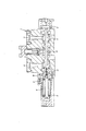
- a control valve 100 according to an embodiment of the present invention will be described with reference to FIG.
- the control valve 100 controls the operation of the actuator by switching between supply and discharge of hydraulic oil to the actuator.
- the control valve 100 includes a spool 12 slidably incorporated in the valve body 1, a first pilot chamber 14 and a second pilot chamber 15 disposed facing both ends of the spool 12, and a first pilot chamber 14.
- a centering spring 13 serving as an urging member that is housed inside and applies a spring force to one end of the spool 12.
- a rod 30 extending into the first pilot chamber 14 is coupled to one end of the spool 12.
- a pair of spring receiving members 31, 32 slidable along the outer periphery of the rod 30 is accommodated in the first pilot chamber 14, and the centering spring 13 is interposed between the pair of spring receiving members 31, 32. .
- the valve body 1 is formed with a pair of actuator ports 16 and 17 communicating with the actuator.
- the actuator port 17 communicates with a pump as a hydraulic pressure supply source, and the actuator port 16 communicates with a tank.
- the hydraulic oil discharged from the pump is supplied to the actuator through the actuator port 17, and the hydraulic oil is discharged from the actuator to the tank through the actuator port 16, so that the actuator operates in one direction.
- the actuator port 16 When the pilot pressure is guided to the second pilot chamber 15, the first pilot chamber 14 communicates with the tank, and the spool 12 moves to the left in FIG. 1 against the spring force of the centering spring 13, the actuator port 16 is pumped.
- the actuator port 17 communicates with the tank.
- the valve body 1 is formed with a signal pressure passage 18 that guides the pilot pressure of the first pilot chamber 14 or the second pilot chamber 15 as the signal pressure of another device.
- a communication groove 19 that opens to the first pilot chamber 14 is formed in an annular shape on the outer peripheral surface of one end of the spool 12.
- the communication groove 19 communicates the first pilot chamber 14 and the signal pressure passage 18 when the spool 12 is in the neutral position.
- the spool 12 is formed with a communication hole 20 that allows the second pilot chamber 15 and the signal pressure passage 18 to communicate with each other.
- a check valve 21 that allows only the flow from the second pilot chamber 15 to the signal pressure passage 18 is interposed in the communication hole 20.
- the actuator port 17 communicates with the pump and the actuator port 16 communicates with the tank.
- the communication groove 19 is kept in communication with the signal pressure passage 18, the pilot pressure in the first pilot chamber 14 is guided to the signal pressure passage 18 through the communication groove 19.
- the check valve 21 is interposed in the communication hole 20, the pilot pressure in the first pilot chamber 14 does not escape from the second pilot chamber 15 to the tank through the signal pressure passage 18 and the communication hole 20. .
- the first pilot chamber 14 communicates with the signal pressure passage 18 through the communication groove 19 when the spool 12 moves to the right in FIG. 1 and then returns to the neutral position shown in FIG.
- the pressure 18 is released from the first pilot chamber 14 to the tank through the communication groove 19. Therefore, no pressure is accumulated in the signal pressure passage 18, and other devices connected to the signal pressure passage 18 do not malfunction.
- the actuator port 16 communicates with the pump and the actuator port 17 communicates with the tank.
- the pilot pressure guided to the second pilot chamber 15 flows into the communication hole 20, pushes the check valve 21 open, and is guided to the signal pressure passage 18.
- the pilot pressure in the second pilot chamber 15 does not escape from the first pilot chamber 14 to the tank through the signal pressure passage 18.
- the communication groove 19 communicates with the signal pressure passage 18, so that the pressure in the signal pressure passage 18 is first through the communication groove 19. From the pilot chamber 14, the tank will come out. Therefore, no pressure is accumulated in the signal pressure passage 18, and other devices connected to the signal pressure passage 18 do not malfunction.
- the signal pressure passage 18 communicates with the first pilot chamber 14 through the communication groove 19, so that it always communicates with the tank. Therefore, pressure does not accumulate in the signal pressure passage 18 and other devices do not malfunction.
- the spool 12 when the spool 12 is moved by the action of the pilot pressure in the first pilot chamber 14, the communication between the first pilot chamber 14 and the signal pressure passage 18 is maintained through the communication groove 19, and the second pilot chamber 14 extends from the second pilot chamber 14 to the second pilot chamber 14. Since the flow of hydraulic oil to the pilot chamber 15 is blocked by the check valve 21, the signal pressure is reliably guided to the other devices through the signal pressure passage 18.
- first pilot chamber 14 and the second pilot chamber 15 are configured not to communicate with each other when the spool 12 is moved by the pilot pressure of the first and second pilot chambers 14 and 15, and compared with the prior art. Since the number of valves can be reduced by one, the number of parts can be reduced.
- the present invention can be applied to a control device that synchronizes an actuator connected to a direction switching valve that is switched by a pilot pressure with another device.
Landscapes
- Engineering & Computer Science (AREA)
- General Engineering & Computer Science (AREA)
- Mechanical Engineering (AREA)
- Physics & Mathematics (AREA)
- Fluid Mechanics (AREA)
- Multiple-Way Valves (AREA)
- Fluid-Driven Valves (AREA)
- Fluid-Pressure Circuits (AREA)
Abstract
Priority Applications (4)
| Application Number | Priority Date | Filing Date | Title |
|---|---|---|---|
| US13/642,885 US8851119B2 (en) | 2011-03-16 | 2012-01-27 | Control valve |
| CN201280001213.5A CN102859245B (zh) | 2011-03-16 | 2012-01-27 | 控制阀 |
| EP12757428.3A EP2687764B1 (fr) | 2011-03-16 | 2012-01-27 | Vanne de commande |
| KR1020127028887A KR101444574B1 (ko) | 2011-03-16 | 2012-01-27 | 제어 밸브 |
Applications Claiming Priority (2)
| Application Number | Priority Date | Filing Date | Title |
|---|---|---|---|
| JP2011-057663 | 2011-03-16 | ||
| JP2011057663A JP5602074B2 (ja) | 2011-03-16 | 2011-03-16 | 制御弁 |
Publications (1)
| Publication Number | Publication Date |
|---|---|
| WO2012124386A1 true WO2012124386A1 (fr) | 2012-09-20 |
Family
ID=46830467
Family Applications (1)
| Application Number | Title | Priority Date | Filing Date |
|---|---|---|---|
| PCT/JP2012/051777 Ceased WO2012124386A1 (fr) | 2011-03-16 | 2012-01-27 | Vanne de commande |
Country Status (6)
| Country | Link |
|---|---|
| US (1) | US8851119B2 (fr) |
| EP (1) | EP2687764B1 (fr) |
| JP (1) | JP5602074B2 (fr) |
| KR (1) | KR101444574B1 (fr) |
| CN (1) | CN102859245B (fr) |
| WO (1) | WO2012124386A1 (fr) |
Cited By (2)
| Publication number | Priority date | Publication date | Assignee | Title |
|---|---|---|---|---|
| WO2019172131A1 (fr) | 2018-03-09 | 2019-09-12 | Kyb株式会社 | Soupape de commande |
| JP2019157949A (ja) * | 2018-03-09 | 2019-09-19 | Kyb株式会社 | 制御弁 |
Families Citing this family (11)
| Publication number | Priority date | Publication date | Assignee | Title |
|---|---|---|---|---|
| US9556970B2 (en) * | 2013-07-19 | 2017-01-31 | Control Components, Inc. | Cascade trim for control valve |
| CN106232907B (zh) * | 2014-04-29 | 2018-11-02 | 沃尔沃建造设备有限公司 | 用于工程机械的流量控制阀 |
| JP2016061427A (ja) * | 2014-09-22 | 2016-04-25 | Kyb株式会社 | 切換弁 |
| JP6440451B2 (ja) | 2014-10-27 | 2018-12-19 | Kyb株式会社 | ロードセンシングバルブ装置 |
| CN105179344B (zh) * | 2015-01-15 | 2017-05-03 | 徐州重型机械有限公司 | 一种分流阀 |
| CN104847924B (zh) * | 2015-03-27 | 2017-04-12 | 浙江工业大学 | 用于可视化观测的高速转阀及流动参数实时检测装置 |
| JP7033463B2 (ja) * | 2018-02-21 | 2022-03-10 | 川崎重工業株式会社 | スプール弁装置 |
| CN108506267B (zh) * | 2018-05-02 | 2019-11-26 | 宁波真格液压科技有限公司 | 一种具有泄压功能的回路选择阀 |
| CN113874648B (zh) * | 2019-05-30 | 2023-12-22 | 沃尔沃建筑设备公司 | 滑阀和包括该滑阀的液压设备 |
| JP7139297B2 (ja) * | 2019-09-25 | 2022-09-20 | 日立建機株式会社 | 流量制御弁 |
| KR102869370B1 (ko) * | 2022-07-14 | 2025-11-06 | 두산모트롤 주식회사 | 절환밸브 및 이를 포함하는 유압 시스템 |
Citations (7)
| Publication number | Priority date | Publication date | Assignee | Title |
|---|---|---|---|---|
| JPS6256602A (ja) * | 1985-09-05 | 1987-03-12 | Yutani Juko Kk | 切換弁 |
| JPH11141696A (ja) * | 1997-11-10 | 1999-05-25 | Hitachi Constr Mach Co Ltd | スプール型方向切換弁システム |
| JPH11280705A (ja) * | 1998-03-27 | 1999-10-15 | Shin Caterpillar Mitsubishi Ltd | 油圧弁操作装置 |
| JP2000097210A (ja) * | 1998-09-18 | 2000-04-04 | Kayaba Ind Co Ltd | 油圧制御装置 |
| JP2001221357A (ja) * | 2000-02-09 | 2001-08-17 | Kayaba Ind Co Ltd | 積層バルブ |
| JP2001241559A (ja) * | 2000-03-01 | 2001-09-07 | Aichi Corp | スプール弁 |
| JP2009013753A (ja) | 2007-07-09 | 2009-01-22 | Kayaba Ind Co Ltd | 建設機械用車両の走行制御装置 |
Family Cites Families (76)
| Publication number | Priority date | Publication date | Assignee | Title |
|---|---|---|---|---|
| US2316944A (en) * | 1941-12-22 | 1943-04-20 | Hydraulic Dev Corp Inc | Valve |
| US2782798A (en) * | 1948-03-18 | 1957-02-26 | Farmingdale Corp | Hydraulic drives for machine tools |
| US2765746A (en) * | 1950-03-11 | 1956-10-09 | Case Co J I | Hydraulic system |
| US2718240A (en) * | 1950-11-17 | 1955-09-20 | Parker Appliance Co | Hydraulic control valve |
| US2745433A (en) * | 1952-02-25 | 1956-05-15 | Hydraulic Unit Specialities Co | Control valve for fluid pressure operated mechanisms |
| US2783745A (en) * | 1953-07-21 | 1957-03-05 | Parker Appliance Co | Valve mechanism for hydraulically operated motors |
| US2977933A (en) * | 1956-02-23 | 1961-04-04 | Landis Tool Co | Mechanism for effecting smooth starting of a hydraulic motor |
| US3023781A (en) * | 1958-05-09 | 1962-03-06 | Raytheon Co | Hydraulic servo valves |
| US2971536A (en) * | 1958-06-26 | 1961-02-14 | Caterpillar Tractor Co | Hydraulic control valve throttling mechanism |
| US2965133A (en) * | 1959-01-08 | 1960-12-20 | New York Air Brake Co | Valve |
| US3093116A (en) * | 1960-04-07 | 1963-06-11 | Gen Motors Corp | High-low speed hoist valve |
| US3160174A (en) * | 1961-03-28 | 1964-12-08 | Parker Hannifin Corp | Remote power shift circuits for spool valves and the like |
| US3200845A (en) * | 1962-07-18 | 1965-08-17 | Kayaba Industry Co Ltd | Pilot operated fluid direction change-over valve |
| US3207178A (en) * | 1963-01-04 | 1965-09-21 | Ohio Brass Co | Combination motor control valve and exhaust flow control |
| US3280842A (en) * | 1965-02-19 | 1966-10-25 | New York Air Brake Co | Valve |
| US3534774A (en) * | 1968-11-14 | 1970-10-20 | Koehring Co | Pressure compensated control valve |
| US3625254A (en) * | 1970-03-12 | 1971-12-07 | Caterpillar Tractor Co | Segmented valve spool |
| US3995532A (en) * | 1974-07-15 | 1976-12-07 | Caterpillar Tractor Co. | Proportional control valve with preconditioned inlet modulating relief valve |
| US3985153A (en) * | 1974-08-28 | 1976-10-12 | Tomco, Inc. | Pressure compensating valve spool assembly for a hydraulic control valve |
| US3998134A (en) * | 1974-11-08 | 1976-12-21 | Tadeusz Budzich | Load responsive fluid control valves |
| US4407328A (en) * | 1975-03-24 | 1983-10-04 | Dresser Industries, Inc. | Clutch-brake steering mechanism for tractors |
| US4015619A (en) * | 1975-03-24 | 1977-04-05 | International Harvester Company | Clutch-brake steering mechanism for tractors |
| US4075842A (en) * | 1976-10-05 | 1978-02-28 | Tadeusz Budzich | Load responsive fluid control system |
| US4256142A (en) * | 1979-08-20 | 1981-03-17 | Hancock Leonard H | Hydraulic control |
| US4311006A (en) * | 1979-10-29 | 1982-01-19 | General Signal Corporation | Pressure compensated steering system |
| US4361169A (en) * | 1979-11-13 | 1982-11-30 | Commercial Shearing, Inc. | Pressure compensated control valves |
| US4287813A (en) * | 1979-12-20 | 1981-09-08 | International Harvester Company | Two-stage concentric hydraulic brake booster |
| US4438780A (en) * | 1980-08-11 | 1984-03-27 | Dresser Industries, Inc. | Clutch-clutch-brake steering mechanism for tractors |
| US4693272A (en) * | 1984-02-13 | 1987-09-15 | Husco International, Inc. | Post pressure compensated unitary hydraulic valve |
| US4561463A (en) * | 1984-03-23 | 1985-12-31 | Koehring Company | Sectional valve having dual pressure relief |
| US4688470A (en) * | 1986-07-21 | 1987-08-25 | Caterpillar Inc. | Compensated fluid flow control valve |
| DE3644269A1 (de) * | 1986-12-23 | 1988-07-07 | Rexroth Mannesmann Gmbh | Wegeventil |
| US4889161A (en) * | 1987-10-02 | 1989-12-26 | Applied Power Inc. | Compensated individual segment flow regulator |
| DE3737392A1 (de) * | 1987-11-04 | 1989-05-24 | Bosch Gmbh Robert | Hydraulisches steuerventil |
| JP2603495B2 (ja) * | 1988-02-09 | 1997-04-23 | 東芝機械株式会社 | 油圧方向制御弁装置 |
| JP2683244B2 (ja) * | 1988-04-14 | 1997-11-26 | 株式会社ゼクセル | 制御弁 |
| US4958553A (en) * | 1988-04-22 | 1990-09-25 | Diesel Kiki Co., Ltd. | Hydraulic controller |
| JPH07103882B2 (ja) * | 1989-03-22 | 1995-11-08 | 株式会社小松製作所 | 圧力補償付液圧弁 |
| US4941508A (en) * | 1989-12-28 | 1990-07-17 | Dana Corporation | Force balanced hydraulic spool valve |
| US5115835A (en) * | 1990-01-26 | 1992-05-26 | Zexel Corporation | Stacked type hydraulic control valve system |
| WO1991014121A1 (fr) * | 1990-03-05 | 1991-09-19 | Komatsu Zenoah Kabushiki Kaisha | Soupape hydraulique de commande |
| US5065793A (en) * | 1990-04-23 | 1991-11-19 | Eaton Corporation | Fluid controller with load sensing priority flow control capability |
| JPH0768962B2 (ja) * | 1990-06-22 | 1995-07-26 | 株式会社ゼクセル | ロードセンシング機能付き方向切換弁 |
| US5240042A (en) * | 1991-10-25 | 1993-08-31 | Raymond Robert E | Linear fluid power actuator assembly |
| JPH06193606A (ja) * | 1992-12-22 | 1994-07-15 | Komatsu Ltd | 圧力補償弁を備えた操作弁 |
| JPH0828505A (ja) * | 1994-07-12 | 1996-02-02 | Komatsu Ltd | 圧力補償弁 |
| JP3441289B2 (ja) * | 1996-04-02 | 2003-08-25 | 日本電産トーソク株式会社 | 油圧回路用弁構造 |
| KR100291438B1 (ko) * | 1996-08-08 | 2001-06-01 | 세구찌 류이찌 | 유압제어장치 |
| JPH1137336A (ja) * | 1997-07-23 | 1999-02-12 | Tokimec Inc | パイロット操作形高速方向切換弁 |
| JP3703265B2 (ja) * | 1997-08-26 | 2005-10-05 | カヤバ工業株式会社 | 油圧制御装置 |
| JPH11280750A (ja) * | 1998-03-31 | 1999-10-15 | Suzuki Motor Corp | ケーブルの位置決め装置 |
| JP3264651B2 (ja) * | 1998-04-28 | 2002-03-11 | 東芝機械株式会社 | 油圧制御装置 |
| GB9810793D0 (en) * | 1998-05-20 | 1998-07-15 | Kongsberg Techmatic Uk Ltd | Variable pressure hydraulic systems |
| JP3919399B2 (ja) * | 1998-11-25 | 2007-05-23 | カヤバ工業株式会社 | 油圧制御回路 |
| US6397890B1 (en) * | 1999-02-15 | 2002-06-04 | Case Corp. | Variable metering fluid control valve |
| US6581639B2 (en) * | 2000-10-20 | 2003-06-24 | Case Corporation | Low leak boom control check valve |
| JP4514324B2 (ja) * | 2000-12-20 | 2010-07-28 | カヤバ工業株式会社 | 油圧制御バルブ |
| US6745564B2 (en) * | 2001-12-21 | 2004-06-08 | Volvo Construction Equipment Holding Sweden Ab | Hydraulic variable control apparatus for heavy construction equipment |
| US6637461B2 (en) * | 2002-03-08 | 2003-10-28 | Husco International, Inc. | Electrically operated hydraulic actuator with force feedback position sensing |
| DE10219718B4 (de) * | 2002-05-02 | 2007-06-06 | Sauer-Danfoss Aps | Hydraulische Ventilanordnung |
| DE10258517B3 (de) * | 2002-12-14 | 2004-06-03 | Sauer-Danfoss (Nordborg) A/S | Hydraulische Ventilanordnung |
| DE10325296A1 (de) * | 2003-06-04 | 2004-12-23 | Bosch Rexroth Ag | Hydraulische Steueranordnung |
| FR2857704B1 (fr) * | 2003-07-16 | 2007-12-28 | Bosch Rexroth Dsi Sas | Distributeur hydraulique a fentes de couple |
| JP4276491B2 (ja) * | 2003-08-04 | 2009-06-10 | 日立建機株式会社 | 方向切換弁ブロック |
| DE10357471A1 (de) * | 2003-12-09 | 2005-07-07 | Bosch Rexroth Ag | Hydraulische Steueranordnung |
| KR100611713B1 (ko) * | 2004-10-14 | 2006-08-11 | 볼보 컨스트럭션 이키프먼트 홀딩 스웨덴 에이비 | 재생기능을 구비한 유압제어밸브 |
| DE102006049584A1 (de) * | 2006-03-13 | 2007-09-20 | Robert Bosch Gmbh | LUDV-Ventilanordnung |
| JP2008002663A (ja) * | 2006-06-26 | 2008-01-10 | Hitachi Constr Mach Co Ltd | スプール弁装置 |
| US7921878B2 (en) * | 2006-06-30 | 2011-04-12 | Parker Hannifin Corporation | Control valve with load sense signal conditioning |
| JP4782711B2 (ja) * | 2007-02-21 | 2011-09-28 | 日立建機株式会社 | 方向制御弁装置およびこの方向制御弁装置を複数備えた方向制御弁装置ブロック |
| DE102008008092A1 (de) * | 2007-11-28 | 2009-06-04 | Robert Bosch Gmbh | Ventilanordnung |
| US8464756B2 (en) * | 2009-09-22 | 2013-06-18 | Eaton Corporation | Spool valve |
| KR101088754B1 (ko) * | 2009-10-20 | 2011-12-01 | 볼보 컨스트럭션 이큅먼트 에이비 | 유압 컨트롤밸브 |
| JP5764217B2 (ja) * | 2010-11-25 | 2015-08-12 | ボルボ コンストラクション イクイップメント アーベー | 建設機械用流量制御弁 |
| JP5602073B2 (ja) * | 2011-03-16 | 2014-10-08 | カヤバ工業株式会社 | 制御弁 |
| EP2791515B1 (fr) * | 2011-12-15 | 2019-02-06 | Eaton Corporation | Tiroir de direction d'écoulement pour distributeur |
-
2011
- 2011-03-16 JP JP2011057663A patent/JP5602074B2/ja active Active
-
2012
- 2012-01-27 WO PCT/JP2012/051777 patent/WO2012124386A1/fr not_active Ceased
- 2012-01-27 KR KR1020127028887A patent/KR101444574B1/ko not_active Expired - Fee Related
- 2012-01-27 CN CN201280001213.5A patent/CN102859245B/zh active Active
- 2012-01-27 US US13/642,885 patent/US8851119B2/en active Active
- 2012-01-27 EP EP12757428.3A patent/EP2687764B1/fr active Active
Patent Citations (7)
| Publication number | Priority date | Publication date | Assignee | Title |
|---|---|---|---|---|
| JPS6256602A (ja) * | 1985-09-05 | 1987-03-12 | Yutani Juko Kk | 切換弁 |
| JPH11141696A (ja) * | 1997-11-10 | 1999-05-25 | Hitachi Constr Mach Co Ltd | スプール型方向切換弁システム |
| JPH11280705A (ja) * | 1998-03-27 | 1999-10-15 | Shin Caterpillar Mitsubishi Ltd | 油圧弁操作装置 |
| JP2000097210A (ja) * | 1998-09-18 | 2000-04-04 | Kayaba Ind Co Ltd | 油圧制御装置 |
| JP2001221357A (ja) * | 2000-02-09 | 2001-08-17 | Kayaba Ind Co Ltd | 積層バルブ |
| JP2001241559A (ja) * | 2000-03-01 | 2001-09-07 | Aichi Corp | スプール弁 |
| JP2009013753A (ja) | 2007-07-09 | 2009-01-22 | Kayaba Ind Co Ltd | 建設機械用車両の走行制御装置 |
Non-Patent Citations (1)
| Title |
|---|
| See also references of EP2687764A4 * |
Cited By (3)
| Publication number | Priority date | Publication date | Assignee | Title |
|---|---|---|---|---|
| WO2019172131A1 (fr) | 2018-03-09 | 2019-09-12 | Kyb株式会社 | Soupape de commande |
| JP2019157949A (ja) * | 2018-03-09 | 2019-09-19 | Kyb株式会社 | 制御弁 |
| US11255354B2 (en) | 2018-03-09 | 2022-02-22 | Kyb Corporation | Control valve |
Also Published As
| Publication number | Publication date |
|---|---|
| US20130037131A1 (en) | 2013-02-14 |
| CN102859245A (zh) | 2013-01-02 |
| CN102859245B (zh) | 2014-01-22 |
| JP2012193789A (ja) | 2012-10-11 |
| EP2687764B1 (fr) | 2016-09-14 |
| KR20130018844A (ko) | 2013-02-25 |
| EP2687764A1 (fr) | 2014-01-22 |
| JP5602074B2 (ja) | 2014-10-08 |
| KR101444574B1 (ko) | 2014-09-24 |
| US8851119B2 (en) | 2014-10-07 |
| EP2687764A4 (fr) | 2015-11-25 |
Similar Documents
| Publication | Publication Date | Title |
|---|---|---|
| WO2012124386A1 (fr) | Vanne de commande | |
| CN103221696B (zh) | 用于施工机械的流量控制阀 | |
| KR101369216B1 (ko) | 파일럿식 3위치 스위칭 밸브 | |
| JP2016053410A5 (fr) | ||
| KR101397218B1 (ko) | 제어 밸브 | |
| KR101816470B1 (ko) | 제어 밸브 장치 | |
| KR101596379B1 (ko) | 유량 증폭기의 자동왕복 유량조절 제어 기구 | |
| WO2016163238A1 (fr) | Soupape de commande et dispositif de régulation de pression de fluide comprenant celle-ci | |
| JP2011196475A (ja) | 油圧回路 | |
| JP5730369B2 (ja) | 切換弁 | |
| WO2017064954A1 (fr) | Système de soupape | |
| WO2016047322A1 (fr) | Vanne de commutation | |
| KR101505016B1 (ko) | 복동식 왕복가능 압력 부스터용 자동 압력조절 제어 기구 | |
| JP6045419B2 (ja) | 油圧制御装置 | |
| CN104520595A (zh) | 用于施工机械的液压控制阀 | |
| JP2009209999A (ja) | 制御弁装置 | |
| WO2019053783A1 (fr) | Soupape de commande | |
| JP4907143B2 (ja) | バルブ構造 | |
| WO2017043252A1 (fr) | Vanne composite et électrovanne l'utilisant | |
| WO2015049728A1 (fr) | Vanne de régulation de débit | |
| WO2019172131A1 (fr) | Soupape de commande | |
| JP2019157950A (ja) | 制御弁 |
Legal Events
| Date | Code | Title | Description |
|---|---|---|---|
| WWE | Wipo information: entry into national phase |
Ref document number: 201280001213.5 Country of ref document: CN |
|
| WWE | Wipo information: entry into national phase |
Ref document number: 13642885 Country of ref document: US |
|
| ENP | Entry into the national phase |
Ref document number: 20127028887 Country of ref document: KR Kind code of ref document: A |
|
| 121 | Ep: the epo has been informed by wipo that ep was designated in this application |
Ref document number: 12757428 Country of ref document: EP Kind code of ref document: A1 |
|
| REEP | Request for entry into the european phase |
Ref document number: 2012757428 Country of ref document: EP |
|
| WWE | Wipo information: entry into national phase |
Ref document number: 2012757428 Country of ref document: EP |
|
| NENP | Non-entry into the national phase |
Ref country code: DE |