WO2012137635A1 - 複合半透膜、複合半透膜エレメントおよび複合半透膜の製造方法 - Google Patents
複合半透膜、複合半透膜エレメントおよび複合半透膜の製造方法 Download PDFInfo
- Publication number
- WO2012137635A1 WO2012137635A1 PCT/JP2012/058049 JP2012058049W WO2012137635A1 WO 2012137635 A1 WO2012137635 A1 WO 2012137635A1 JP 2012058049 W JP2012058049 W JP 2012058049W WO 2012137635 A1 WO2012137635 A1 WO 2012137635A1
- Authority
- WO
- WIPO (PCT)
- Prior art keywords
- composite semipermeable
- membrane
- semipermeable membrane
- layer
- functional layer
- Prior art date
- Legal status (The legal status is an assumption and is not a legal conclusion. Google has not performed a legal analysis and makes no representation as to the accuracy of the status listed.)
- Ceased
Links
Classifications
-
- B—PERFORMING OPERATIONS; TRANSPORTING
- B01—PHYSICAL OR CHEMICAL PROCESSES OR APPARATUS IN GENERAL
- B01D—SEPARATION
- B01D71/00—Semi-permeable membranes for separation processes or apparatus characterised by the material; Manufacturing processes specially adapted therefor
- B01D71/06—Organic material
- B01D71/56—Polyamides, e.g. polyester-amides
-
- B—PERFORMING OPERATIONS; TRANSPORTING
- B01—PHYSICAL OR CHEMICAL PROCESSES OR APPARATUS IN GENERAL
- B01D—SEPARATION
- B01D69/00—Semi-permeable membranes for separation processes or apparatus characterised by their form, structure or properties; Manufacturing processes specially adapted therefor
- B01D69/12—Composite membranes; Ultra-thin membranes
- B01D69/1216—Three or more layers
-
- B—PERFORMING OPERATIONS; TRANSPORTING
- B01—PHYSICAL OR CHEMICAL PROCESSES OR APPARATUS IN GENERAL
- B01D—SEPARATION
- B01D63/00—Apparatus in general for separation processes using semi-permeable membranes
- B01D63/10—Spiral-wound membrane modules
-
- B—PERFORMING OPERATIONS; TRANSPORTING
- B01—PHYSICAL OR CHEMICAL PROCESSES OR APPARATUS IN GENERAL
- B01D—SEPARATION
- B01D63/00—Apparatus in general for separation processes using semi-permeable membranes
- B01D63/10—Spiral-wound membrane modules
- B01D63/107—Specific properties of the central tube or the permeate channel
-
- B—PERFORMING OPERATIONS; TRANSPORTING
- B01—PHYSICAL OR CHEMICAL PROCESSES OR APPARATUS IN GENERAL
- B01D—SEPARATION
- B01D67/00—Processes specially adapted for manufacturing semi-permeable membranes for separation processes or apparatus
- B01D67/0002—Organic membrane manufacture
- B01D67/0009—Organic membrane manufacture by phase separation, sol-gel transition, evaporation or solvent quenching
- B01D67/0013—Casting processes
-
- B—PERFORMING OPERATIONS; TRANSPORTING
- B01—PHYSICAL OR CHEMICAL PROCESSES OR APPARATUS IN GENERAL
- B01D—SEPARATION
- B01D67/00—Processes specially adapted for manufacturing semi-permeable membranes for separation processes or apparatus
- B01D67/0002—Organic membrane manufacture
- B01D67/0009—Organic membrane manufacture by phase separation, sol-gel transition, evaporation or solvent quenching
- B01D67/0016—Coagulation
-
- B—PERFORMING OPERATIONS; TRANSPORTING
- B01—PHYSICAL OR CHEMICAL PROCESSES OR APPARATUS IN GENERAL
- B01D—SEPARATION
- B01D69/00—Semi-permeable membranes for separation processes or apparatus characterised by their form, structure or properties; Manufacturing processes specially adapted therefor
- B01D69/10—Supported membranes; Membrane supports
- B01D69/107—Organic support material
-
- B—PERFORMING OPERATIONS; TRANSPORTING
- B01—PHYSICAL OR CHEMICAL PROCESSES OR APPARATUS IN GENERAL
- B01D—SEPARATION
- B01D69/00—Semi-permeable membranes for separation processes or apparatus characterised by their form, structure or properties; Manufacturing processes specially adapted therefor
- B01D69/12—Composite membranes; Ultra-thin membranes
- B01D69/125—In situ manufacturing by polymerisation, polycondensation, cross-linking or chemical reaction
-
- B—PERFORMING OPERATIONS; TRANSPORTING
- B01—PHYSICAL OR CHEMICAL PROCESSES OR APPARATUS IN GENERAL
- B01D—SEPARATION
- B01D71/00—Semi-permeable membranes for separation processes or apparatus characterised by the material; Manufacturing processes specially adapted therefor
- B01D71/06—Organic material
- B01D71/66—Polymers having sulfur in the main chain, with or without nitrogen, oxygen or carbon only
- B01D71/68—Polysulfones; Polyethersulfones
-
- B—PERFORMING OPERATIONS; TRANSPORTING
- B01—PHYSICAL OR CHEMICAL PROCESSES OR APPARATUS IN GENERAL
- B01D—SEPARATION
- B01D2323/00—Details relating to membrane preparation
- B01D2323/12—Specific ratios of components used
-
- B—PERFORMING OPERATIONS; TRANSPORTING
- B01—PHYSICAL OR CHEMICAL PROCESSES OR APPARATUS IN GENERAL
- B01D—SEPARATION
- B01D2325/00—Details relating to properties of membranes
- B01D2325/04—Characteristic thickness
-
- B—PERFORMING OPERATIONS; TRANSPORTING
- B01—PHYSICAL OR CHEMICAL PROCESSES OR APPARATUS IN GENERAL
- B01D—SEPARATION
- B01D2325/00—Details relating to properties of membranes
- B01D2325/30—Chemical resistance
Definitions
- the present invention relates to a composite semipermeable membrane useful for selective separation of a liquid mixture.
- the composite semipermeable membrane of the present invention can be suitably used for desalination of seawater or brine, for example.
- membrane separation methods there are various techniques for removing substances (eg, salts) dissolved in a solvent (eg, water), but in recent years, the use of membrane separation methods has expanded as a process for saving energy and resources. is doing.
- membranes used in the membrane separation method include microfiltration membranes, ultrafiltration membranes, nanofiltration membranes, and reverse osmosis membranes. These membranes are used, for example, in the case of obtaining drinking water from seawater, brine, water containing harmful substances, etc., in the production of industrial ultrapure water, wastewater treatment, recovery of valuables and the like.
- the composite semipermeable membrane includes an active layer obtained by crosslinking a gel layer and a polymer on a porous support membrane, and an active layer obtained by polycondensation of monomers on the porous support membrane.
- an active layer obtained by crosslinking a gel layer and a polymer on a porous support membrane There are two types. Among these, composite semipermeable membranes obtained by coating a porous support membrane with a separation functional layer made of a crosslinked polyamide obtained by polycondensation reaction of a polyfunctional amine and a polyfunctional acid halide have permeability and selective separation. It is widely used as a highly reliable separation membrane.
- Reverse osmosis membranes used in desalination plants are required to have higher water permeability in order to further reduce running costs.
- a method is known in which a composite semipermeable membrane provided with a crosslinked polyamide polymer as a separation active layer is brought into contact with an aqueous solution containing nitrous acid (Patent Document 1).
- This treatment can improve the water permeability of the composite semipermeable membrane while maintaining the boron removal rate before the treatment, but further high water permeability is desired.
- Patent Document 3 In order to improve the alkali resistance of the composite semipermeable membrane, a method (Patent Document 3) is disclosed in which a hydrogen ion concentration aqueous solution having a pH of 9 to 13 is contacted with the composite semipermeable membrane. Moreover, in order to improve the acid resistance of a composite semipermeable membrane, a method (Patent Document 4) is disclosed in which a cyclic sulfate is brought into contact with the composite semipermeable membrane.
- JP 2007-090192 A Japanese Patent Laid-Open No. 9-19630 JP 2006-102624 A JP 2010-234284 A
- An object of the present invention is to provide a high performance composite semipermeable membrane having high water permeability and high chemical resistance.
- the present invention has the following configuration.
- a high-performance composite semipermeable membrane having high water permeability and high chemical resistance and little change in membrane performance before and after cleaning with a chemical solution is obtained.
- this membrane it is stable over a long period of time. Expected to continue driving.
- the present invention is a composite semipermeable membrane in which a polyamide separation functional layer is formed on a microporous support membrane comprising a substrate and a porous support, and the standard deviation of the thickness of the separation functional layer is 2. It is a composite semipermeable membrane having a thickness of 00 nm or less.
- the separation functional layer that substantially has the separation performance of ions and the like.
- the microporous support membrane is composed of a base material and a porous support and has substantially no separation performance and is intended to give strength to the separation functional layer.
- the thickness of the microporous support membrane affects the strength of the composite semipermeable membrane and the packing density when the composite semipermeable membrane is used as an element.
- the thickness of the microporous support membrane is preferably in the range of 30 ⁇ m or more and 300 ⁇ m or less, more preferably in the range of 50 ⁇ m or more and 300 ⁇ m or less, more preferably 50 ⁇ m or more.
- the range is 250 ⁇ m or less, more preferably 100 ⁇ m or more and 250 ⁇ m or less.
- the thickness of the porous support is preferably in the range of 10 ⁇ m to 200 ⁇ m, more preferably in the range of 20 ⁇ m to 100 ⁇ m, and still more preferably in the range of 30 ⁇ m to 100 ⁇ m.
- the thickness of the substrate is preferably in the range of 10 to 250 ⁇ m, more preferably in the range of 20 to 200 ⁇ m.
- the thickness of each layer and film means an average value.
- the average value represents an arithmetic average value. That is, the thickness of each layer and film is determined by calculating the average value of the thicknesses of 20 points measured at intervals of 20 ⁇ m in the direction orthogonal to the thickness direction (film surface direction) by cross-sectional observation.
- the base material constituting the microporous support membrane examples include a polyester polymer, a polyamide polymer, a polyolefin polymer, a mixture and a copolymer thereof, and the like.
- a polyester polymer is preferred because a microporous support film having excellent durability such as mechanical strength, heat resistance, water resistance and chemical resistance can be obtained.
- the polyester polymer used in the present invention is a polyester obtained by polycondensation of an acid component and an alcohol component.
- the acid component include aromatic carboxylic acids such as terephthalic acid, isophthalic acid, and phthalic acid; aliphatic dicarboxylic acids such as adipic acid and sebacic acid; and alicyclic dicarboxylic acids such as cyclohexanecarboxylic acid.
- the alcohol component ethylene glycol, diethylene glycol, polyethylene glycol, or the like can be used as the alcohol component.
- polyester polymer examples include polyethylene terephthalate resin, polybutylene terephthalate resin, polytrimethylene terephthalate resin, polyethylene naphthalate resin, polylactic acid resin, and polybutylene succinate resin.
- polyester polymer examples include coalescence.
- the base material it is preferable to use a base material made of fibers in terms of strength, unevenness forming ability and fluid permeability.
- a base material made of fibers in terms of strength, unevenness forming ability and fluid permeability.
- a long fiber nonwoven fabric or a short fiber nonwoven fabric can be preferably used.
- the long fiber nonwoven fabric can suppress the peeling of the porous support layer by being excellent in permeability when a polymer solution is cast on a base material.
- the film can be prevented from becoming non-uniform due to the fluffing of the substrate and the like, and the occurrence of defects such as pinholes can be suppressed.
- the fibers in the surface layer on the side opposite to the porous support layer are longitudinally oriented as compared with the fibers on the surface layer on the porous support layer side. According to such a structure, not only a high effect of preventing membrane breakage and the like by realizing strength is realized, but also when the unevenness is imparted to the composite semipermeable membrane, the porous support layer and the base material are included. The moldability of the laminate is also improved, and the uneven shape on the surface of the composite semipermeable membrane is stabilized, which is preferable.
- the fiber orientation degree in the surface layer on the side opposite to the porous support layer of the long-fiber nonwoven fabric is preferably 0 ° to 25 °, and the fiber orientation degree in the surface layer on the porous support layer side And the orientation degree difference is preferably 10 ° to 90 °.
- a heating process is included, but a phenomenon occurs in which the porous support layer or the separation functional layer contracts due to the heating.
- the shrinkage is remarkable in the width direction where no tension is applied in continuous film formation. Since shrinkage causes problems in dimensional stability and the like, a substrate having a small rate of thermal dimensional change is desired.
- the difference between the fiber orientation degree on the surface layer opposite to the porous support layer and the fiber orientation degree on the porous support layer side surface layer is 10 ° to 90 °, the change in the width direction due to heat is suppressed. Can also be preferable.
- the degree of fiber orientation is an index indicating the fiber orientation of the nonwoven fabric substrate constituting the porous support layer, and the film forming direction when continuous film formation is performed, that is, the longitudinal direction of the nonwoven fabric substrate is 0 °.
- the average angle of the fibers constituting the nonwoven fabric substrate when the direction perpendicular to the film forming direction that is, the width direction of the nonwoven fabric substrate is 90 °. Accordingly, the closer to 0 ° the fiber orientation, the longer the orientation, and the closer to 90 °, the lateral orientation.
- the degree of fiber orientation was obtained by randomly collecting 10 small sample pieces from a nonwoven fabric, photographing the surface of the sample with a scanning electron microscope at a magnification of 100 to 1000 times, and selecting 10 samples arbitrarily selected from each sample.
- the angle when the longitudinal direction (longitudinal direction, film forming direction) of the nonwoven fabric is 0 ° and the width direction (lateral direction) of the nonwoven fabric is 90 ° is measured, and the average value thereof is the first decimal place. Calculate the fiber orientation by rounding off the position.
- porous support material constituting the microporous support film examples include polysulfone, polyethersulfone, polyamide, polyester, cellulose polymer, vinyl polymer, polyphenylene sulfide, polyphenylene sulfide sulfone, polyphenylene sulfone, and polyphenylene oxide. Homopolymers or copolymers can be used alone or blended. Here, cellulose acetate and cellulose nitrate can be used as the cellulose polymer, and polyethylene, polypropylene, polyvinyl chloride, polyacrylonitrile and the like can be used as the vinyl polymer.
- homopolymers or copolymers such as polysulfone, polyamide, polyester, cellulose acetate, cellulose nitrate, polyvinyl chloride, polyacrylonitrile, polyphenylene sulfide, and polyphenylene sulfide sulfone are preferable. More preferred is cellulose acetate, polysulfone, polyphenylene sulfide sulfone, or polyphenylene sulfone. Further, among these materials, polysulfone can be most preferably used because it has high chemical, mechanical and thermal stability and is easy to mold.
- polysulfone composed of repeating units represented by the following chemical formula because the pore diameter can be easily controlled and the dimensional stability is high.
- an N, N-dimethylformamide (hereinafter referred to as DMF) solution of the above polysulfone is applied on a substrate to a certain thickness and wet coagulated in water, so that most of the surface has a diameter number.
- a microporous support membrane having fine pores of 1 to 30 nm can be obtained.
- a base material a polyester cloth or a polyester non-woven cloth is used, and a polysulfone solution is applied on the base material to a certain thickness and wet coagulated in water.
- a microporous support membrane having fine pores of 10 nm or less can be obtained.
- the separation functional layer in the present invention contains polyamide as a main component.
- the polyamide constituting the separation functional layer can be formed by performing interfacial polycondensation between a polyfunctional amine and a polyfunctional acid halide on a microporous support membrane.
- the phrase “containing polyamide as a main component” means that the polyamide accounts for 60% by weight or more, preferably 80% by weight or more, more preferably 90% by weight or more of the separation functional layer. Includes a configuration containing only polyamide.
- the polyfunctional amine is an amine having at least two primary and / or secondary amino groups in one molecule, and at least one of the amino groups is a primary amino group.
- the polyfunctional amine include phenylenediamine, xylylenediamine, and 1,3,5-triaminobenzene in which two amino groups are bonded to the benzene ring in any of the ortho, meta, and para positions.
- Aromatic polyfunctional amines such as 1,2,4-triaminobenzene, 3,5-diaminobenzoic acid, 3-aminobenzylamine and 4-aminobenzylamine; aliphatic amines such as ethylenediamine and propylenediamine; Examples include alicyclic polyfunctional amines such as 2-diaminocyclohexane, 1,4-diaminocyclohexane, 4-aminopiperidine, 4-aminoethylpiperazine and the like. Among them, in view of selective separation, permeability and heat resistance of the membrane, an aromatic polyfunctional amine having 2 to 4 primary and / or secondary amino groups in one molecule is preferable.
- a polyfunctional aromatic amine a polyfunctional amine selected from m-phenylenediamine, p-phenylenediamine and 1,3,5-triaminobenzene is preferably used.
- m-PDA m-phenylenediamine
- These polyfunctional amines may be used alone or in combination of two or more. When using 2 or more types simultaneously, the said amines may be combined and the said amine and the amine which has at least 2 secondary amino group in 1 molecule may be combined. Examples of the amine having at least two secondary amino groups in one molecule include piperazine and 1,3-bispiperidylpropane.
- the polyfunctional acid halide refers to an acid halide having at least two carbonyl halide groups in one molecule.
- examples of the trifunctional acid halide include trimesic acid chloride, 1,3,5-cyclohexanetricarboxylic acid trichloride, 1,2,4-cyclobutanetricarboxylic acid trichloride, and the like.
- bifunctional acid halide examples include aromatic bifunctional acid halides such as biphenyl dicarboxylic acid dichloride, azobenzene dicarboxylic acid dichloride, terephthalic acid chloride, isophthalic acid chloride, and naphthalene dicarboxylic acid chloride; adipoyl chloride, sebacoyl chloride, and the like.
- aromatic bifunctional acid halides such as biphenyl dicarboxylic acid dichloride, azobenzene dicarboxylic acid dichloride, terephthalic acid chloride, isophthalic acid chloride, and naphthalene dicarboxylic acid chloride; adipoyl chloride, sebacoyl chloride, and the like.
- Aliphatic bifunctional acid halides; cycloaliphatic difunctional acid halides such as cyclopentane dicarboxylic acid dichloride, cyclohexane dicarboxylic acid dichloride, and
- the polyfunctional acid halide is preferably a polyfunctional acid chloride, and considering the selective separation property and heat resistance of the membrane, 2 to 4 polyfunctional acid halides are used in one molecule.
- the polyfunctional aromatic acid chloride having a carbonyl chloride group is preferred. Among them, it is more preferable to use trimesic acid chloride from the viewpoint of easy availability and easy handling.
- These polyfunctional acid halides may be used alone or in combination of two or more.
- this invention is characterized by the standard deviation of the film thickness of a polyamide separation function layer being 2.00 nm or less.
- the film thickness of the polyamide separation functional layer can be analyzed using an observation technique such as a transmission electron microscope, TEM tomography, focused ion beam / scanning electron microscope (FIB / SEM). For example, when observing by TEM tomography, the composite semipermeable membrane is treated with a water-soluble polymer to maintain the shape of the polyamide separation functional layer, and then stained with osmium tetroxide or the like for observation.
- the polyamide separation functional layer in the present invention forms a pleated structure.
- the film thickness is defined as the shortest distance from a certain point on the outer surface of the pleated structure to the inner surface.
- the standard deviation of the film thickness and the average film thickness of the polyamide separation functional layer are calculated from measured values of at least 50 locations.
- High chemical resistance is imparted when the standard deviation of the film thickness of the polyamide separation functional layer is 2.00 nm or less. If the standard deviation of the film thickness of the polyamide separation functional layer is larger than 2.00 nm, the thin part of the film is locally deteriorated during chemical cleaning, and the film performance is likely to deteriorate.
- a uniform polyamide separation functional layer having a standard deviation of film thickness of 2.00 nm or less can prevent local deterioration and can be stably operated over a long period of time.
- the average film thickness of the polyamide separation functional layer is preferably 14 nm or more and 22 nm or less, and more preferably 16 nm or more and 20 nm or less.
- the average film thickness is less than 14 nm, sufficient permeation flux can be obtained, but deterioration during chemical cleaning tends to occur.
- the average film thickness is larger than 22 nm, deterioration during chemical cleaning can be suppressed, but sufficient permeation flux cannot be obtained.
- the average film thickness is 14 nm or more and 22 nm or less, the permeation flux and the durability against chemical cleaning are balanced, and a high-performance film is obtained.
- a porous support having a multilayer structure in order to set the standard deviation of the film thickness of the polyamide separation functional layer to 2.00 nm or less, it is preferable to use a porous support having a multilayer structure.
- the porous support having a multilayer structure has at least two layers: a first layer in contact with the substrate and a second layer in contact with the polyamide separation functional layer.
- the first layer preferably has pores having a pore diameter of 0.1 ⁇ m or more and 1 ⁇ m or less in order to reduce water permeation resistance and to give a good pleated structure to the polyamide separation functional layer.
- the second layer retains the polyfunctional amine in an amount necessary for forming the polyamide separation functional layer, and has a pore size in order to uniformly release the polyfunctional amine in the interfacial polycondensation forming the polyamide separation functional layer. It is preferable to have pores of 1 nm or more and 10 nm or less.
- the polyamide has a very uniform thickness and a small standard deviation in thickness. It was found that a separation functional layer was formed.
- the first layer and the second layer do not necessarily have to be clearly separated, and the interface between the first layer and the second layer may be fused.
- region which contacts the polyamide separation functional layer of a 2nd layer should just have the pore which has said pore diameter, respectively.
- interfacial polycondensation is carried out by bringing a porous support holding a polyfunctional amine aqueous solution into contact with a polyfunctional acid halide organic solvent solution. That is, the polyfunctional amine aqueous solution is released from the porous support, thereby reacting with the polyfunctional acid halide to form a polyamide separation functional layer. Since the porous support has a multilayer structure as described above, the polyfunctional amine aqueous solution released from the porous support has a uniform and appropriate flow rate, so that the film thickness is uniform and good. It is considered that a polyamide separation functional layer imparting a pleated structure can be obtained.
- the form of the microporous support membrane can be observed with a scanning electron microscope, a transmission electron microscope, or an atomic microscope.
- a scanning electron microscope the porous support is peeled off from the substrate, and then cut by a freeze cleaving method to obtain a sample for cross-sectional observation.
- the sample is thinly coated with platinum, platinum-palladium or ruthenium tetroxide, preferably ruthenium tetroxide, and observed with a high-resolution field emission scanning electron microscope (UHR-FE-SEM) at an acceleration voltage of 3 to 6 kV.
- UHR-FE-SEM high-resolution field emission scanning electron microscope
- Hitachi S-900 electron microscope can be used as the high-resolution field emission scanning electron microscope.
- the film thickness and pore diameter of the microporous support membrane are determined from the obtained electron micrograph.
- the film thickness and the hole diameter mean an average value.
- the microporous support membrane constituting the composite semipermeable membrane of the present invention is formed by applying and solidifying a polymer solution for forming a porous support on a substrate.
- the porous support As described above, as the porous support, the first layer excellent in the permeation flow rate after film formation and the polyfunctional amine in an amount necessary for forming the polyamide separation functional layer are retained, and the polyfunctional amine is uniformly formed.
- a polymer solution A for forming the first layer and a polymer solution for forming the second layer It is preferable that B has a different composition.
- the polysulfone concentration of the polymer solution A is preferably 12% by weight or more, more preferably 13% by weight or more. It is.
- the polysulfone concentration of the polymer solution A is preferably 18% by weight or less, more preferably 15% by weight or less.
- the communication hole is formed to be relatively small, so that a preferable hole diameter as the first layer can be easily obtained.
- the polymer concentration is 18% by weight or less, the phase separation can proceed sufficiently before the polymer is solidified, so that a porous structure can be easily obtained.
- the concentration of polysulfone in the polymer solution B is preferably 14% by weight or more, more preferably 15% by weight or more, more preferably 15. It is 5% by weight or more, more preferably 16% by weight or more.
- the polysulfone concentration of the polymer solution B is preferably 25% by weight or less, more preferably 18% by weight or less.
- the polysulfone concentration of the polymer solution B is less than 14% by weight, the surface pores tend to be large, and it is difficult to uniformly supply the amine solution when forming the polyamide separation functional layer.
- the polysulfone concentration of the polymer solution B exceeds 25% by weight, the surface pores tend to be small, and it becomes difficult to supply a sufficient amount of amine solution when forming the polyamide separation functional layer. .
- the polymer concentration of the polymer solution B is preferably larger than the polymer concentration of the polymer solution A.
- the temperature of the polymer solution when applying the polymer solution may be a solution in the range of 10 ° C. or more and 60 ° C. or less when polysulfone is used.
- the temperature of the polymer solution is more preferably in the range of 20 ° C to 35 ° C. If the temperature of the polymer solution is less than 10 ° C., the polymer solidifies before the phase separation between the polymer and the solvent is sufficiently advanced, so that it becomes difficult to obtain a porous structure. On the other hand, when the temperature of the polymer solution exceeds 60 ° C., the phase separation tends to proceed excessively and the communication holes tend to be large, making it difficult to obtain a predetermined pore diameter.
- the polymer solution A that forms the first layer on the substrate and simultaneously apply the polymer solution B that forms the second layer on the first layer.
- a high-density skin layer is formed on the surface of the first layer formed by phase separation of polymer solution A. It is formed and the permeation
- “simultaneously apply” means that the polymer solution A is in contact with the polymer solution B before reaching the substrate, that is, when the polymer solution A is applied to the substrate. This includes a state in which the polymer solution B is already applied on the polymer solution A.
- the polymer solution can be applied onto the substrate by various coating methods, but pre-metering coating methods such as die coating, slide coating, curtain coating, etc., which can supply an accurate amount of the coating solution, are preferably applied. . Further, in the formation of the porous support having a multilayer structure, the polymer solution A for forming the first layer and the polymer solution B for forming the second layer are simultaneously applied using a double slit die coater. The double slit die method is more preferably used.
- the resin contained in the polymer solution A and the polymer solution B may be the same resin or different resins.
- various characteristics such as strength characteristics, permeability characteristics, and surface characteristics of the microporous support membrane to be manufactured can be adjusted in a wider range.
- the solvent contained in the polymer solution A and the polymer solution B may be the same solvent or different solvents as long as they are good polymers.
- the strength can be selected appropriately in consideration of the strength characteristics of the microporous support membrane to be produced and the impregnation of the polymer solution into the substrate.
- the good solvent is one that dissolves the polymer material.
- good solvents include N-methyl-2-pyrrolidone, tetrahydrofuran, dimethyl sulfoxide, tetramethylurea; amides such as dimethylacetamide and dimethylformamide; lower alkyl ketones such as acetone and methylethylketone; trimethyl phosphate and ⁇ -butyrolactone. Esters and lactones; and mixed solvents thereof.
- the polymer solution may contain an additive for adjusting the pore diameter, porosity, hydrophilicity, elastic modulus and the like of the obtained microporous support membrane.
- Additives for adjusting the pore size and porosity include water, alcohols, polyethylene glycol, polyvinyl pyrrolidone, polyvinyl alcohol, water-soluble polymers such as polyacrylic acid or salts thereof, lithium chloride, sodium chloride, chloride Examples include inorganic salts such as calcium and lithium nitrate, formaldehyde, formamide and the like, but are not limited thereto.
- additives for adjusting hydrophilicity and elastic modulus include various surfactants.
- the polymer solution is solidified by immersing the substrate coated with the polymer solution in a liquid that is non-solvent for the polymer and miscible with the solvent and additives.
- a porous support is formed.
- Non-solvents include, for example, water; aliphatic hydrocarbons such as hexane, pentane and trichloroethylene; aromatic hydrocarbons such as benzene and toluene; methanol, ethanol, ethylene glycol, diethylene glycol, triethylene glycol, propylene glycol, butylene glycol, Examples include pentanediol, hexanediol, aliphatic alcohols such as low molecular weight polyethylene glycol, and mixed solvents thereof.
- the membrane form of the microporous support membrane obtained by the composition of the polymer solution changes, thereby changing the membrane-forming property of the composite semipermeable membrane.
- the temperature of the coagulation bath is preferably ⁇ 20 ° C. to 100 ° C. More preferably, it is 10 to 30 ° C. When the temperature of the coagulation bath is higher than this range, the vibration of the coagulation bath surface becomes intense due to thermal motion, and the smoothness of the film surface after film formation tends to decrease. On the other hand, if the temperature is too low, the solidification rate is slowed, causing a problem in film forming properties.
- the obtained microporous support membrane is washed with hot water in order to remove the membrane-forming solvent remaining in the membrane.
- the temperature of the hot water at this time is preferably 50 to 100 ° C, more preferably 60 to 95 ° C.
- the temperature of the hot water is higher than this range, the degree of shrinkage of the microporous support membrane increases and the water permeability decreases. Conversely, when the temperature of hot water is low, the cleaning effect is small.
- the polyamide separation functional layer uses an aqueous solution containing the aforementioned polyfunctional amine and an organic solvent solution immiscible with water containing the polyfunctional acid halide, and interfacial polycondensation on the surface of the microporous support membrane. Can be formed.
- the concentration of the polyfunctional amine in the polyfunctional amine aqueous solution is preferably in the range of 0.1% by weight to 20% by weight, and more preferably in the range of 0.5% by weight to 15% by weight. When the concentration of the polyfunctional amine is within this range, the resulting membrane can have sufficient water permeability and salt and boron removal performance.
- a surfactant, an organic solvent, an alkaline compound, an antioxidant, or the like may be contained.
- the surfactant has the effect of improving the wettability of the microporous support membrane surface and reducing the interfacial tension between the aqueous amine solution and the organic solvent.
- the organic solvent may act as a catalyst for the interfacial polycondensation reaction, and when added, the interfacial polycondensation reaction may be efficiently performed.
- the concentration of the polyfunctional acid halide in the organic solvent solution is preferably in the range of 0.01 wt% to 10 wt%, and more preferably in the range of 0.02 wt% to 2.0 wt%. preferable.
- a sufficient reaction rate can be obtained by setting the concentration to 0.01% by weight or more.
- production of a side reaction can be suppressed by making a density
- organic solvent a solvent that dissolves the polyfunctional acid halide, does not destroy the microporous support membrane, and is inert to the polyfunctional amine compound and the polyfunctional acid halide is desirable.
- organic solvent a solvent that dissolves the polyfunctional acid halide, does not destroy the microporous support membrane, and is inert to the polyfunctional amine compound and the polyfunctional acid halide.
- hydrocarbon compounds such as hexane, heptane, octane, nonane and decane.
- an aqueous polyfunctional amine solution is brought into contact with the microporous support membrane.
- the contact is preferably performed uniformly and continuously on the surface of the microporous support membrane.
- Specific examples include a method of coating a polyfunctional amine aqueous solution on a microporous support membrane and a method of immersing the microporous support membrane in a polyfunctional amine aqueous solution.
- the contact time between the microporous support membrane and the polyfunctional amine aqueous solution is preferably in the range of 5 seconds to 10 minutes, and more preferably in the range of 10 seconds to 3 minutes.
- the solution After the polyfunctional amine aqueous solution is brought into contact with the microporous support membrane, the solution is sufficiently drained so that no droplets remain on the membrane. By sufficiently draining the liquid, it is possible to prevent the removal performance of the composite semipermeable membrane from being deteriorated due to the remaining portion of the droplet after the formation of the composite semipermeable membrane.
- a method for draining for example, as described in Japanese Patent Application Laid-Open No. 2-78428, the microporous support membrane after contacting with the polyfunctional amine aqueous solution is vertically gripped to allow the excess aqueous solution to flow down naturally.
- a method or a method of forcibly draining an air stream such as nitrogen from an air nozzle can be used.
- the membrane surface after draining, the membrane surface can be dried to partially remove water from the aqueous solution.
- an organic solvent solution containing a polyfunctional acid halide is brought into contact with the microporous support membrane after contacting with the polyfunctional amine aqueous solution, and a polyamide separation functional layer is formed by interfacial polycondensation.
- the method of bringing the organic solvent solution containing the polyfunctional acid halide into contact with the microporous support membrane may be performed in the same manner as the method of coating the microporous support membrane with the polyfunctional amine aqueous solution.
- the microporous support membrane is sufficiently covered with the polyamide separation functional layer, and the organic solvent solution containing the polyfunctional acid halide brought into contact during the interfacial polycondensation step is microporous. It is important to remain on the support membrane. For this reason, the time for performing the interfacial polycondensation is preferably from 0.1 second to 3 minutes, and more preferably from 0.1 second to 1 minute. By setting the interfacial polycondensation time to 0.1 seconds or more and 3 minutes or less, the microporous support membrane can be sufficiently covered with the polyamide separation functional layer, and an organic material containing a polyfunctional acid halide is included. The solvent solution can be retained on the microporous support membrane.
- the excess solvent is drained.
- a method for draining for example, a method in which a film is held in a vertical direction and excess organic solvent is allowed to flow down and removed can be used.
- the time for gripping in the vertical direction is preferably 1 minute or more and 5 minutes or less, and more preferably 1 minute or more and 3 minutes or less. If the time is too short, the separation functional layer is not completely formed, and if it is too long, the organic solvent is overdried and a defective portion is generated in the polyamide separation functional layer, and the performance of the resulting membrane is deteriorated.
- the composite semipermeable membrane of the present invention thus produced has a large number of pores together with a raw water channel material such as a plastic net, a permeate channel material such as tricot, and a film for increasing pressure resistance as necessary. Is wound around a cylindrical water collecting pipe and is suitably used as a spiral composite semipermeable membrane element. Furthermore, a composite semipermeable membrane module in which these elements are connected in series or in parallel and accommodated in a pressure vessel can be obtained.
- the above-described composite semipermeable membrane and its elements or modules can be combined with a pump for supplying raw water to them, a device for pretreating the raw water, or the like to constitute a fluid separation device.
- a separation device By using this separation device, raw water can be separated into permeated water such as drinking water and concentrated water that has not permeated through the membrane, and water suitable for the purpose can be obtained.
- the operation pressure when the treated water passes through the composite semipermeable membrane is preferably 0.5 MPa or more and 10 MPa or less.
- the feed water temperature is preferably 5 ° C. or higher and 45 ° C. or lower.
- scales such as magnesium may be generated in the case of feed water with a high salt concentration such as seawater, and there is a concern about deterioration of the membrane due to high pH operation. Is preferred.
- Examples of raw water to be treated by the composite semipermeable membrane according to the present invention include liquid mixtures containing 500 mg / L or more and 100 g / L or less of TDS (Total Dissolved Solids) such as seawater, brine, and drainage. It is done.
- TDS Total Dissolved Solids
- mass / volume or expressed as “weight ratio” by regarding 1 L as 1 kg.
- the solution filtered through a 0.45 ⁇ m filter can be calculated from the weight of the residue by evaporating at a temperature of 39.5 ° C. or higher and 40.5 ° C. or lower. Convert.
- the composite semipermeable membrane of the present invention is characterized by having high chemical resistance, but it is appropriate to use the resistance to each of pH 1 and pH 13 as an index for chemical resistance. is there. Since pH 1 is the strongest condition as pH during acid washing in membrane filtration operation, and pH 13 is the strongest condition as pH during alkali washing, if resistance to each aqueous solution of pH 1 and pH 13 is exhibited, acid or This is because it is ensured that the film is not easily deteriorated even when cleaning with alkali is performed.
- the composite semipermeable membrane was embedded with PVA and then stained with osmium tetroxide to obtain a measurement sample.
- the obtained sample was photographed using TEM tomography, and the obtained 3D image was analyzed by analysis software.
- JEOL field emission analytical electron microscope JEM2100F was used for TEM tomography analysis.
- the shortest distance from a certain point on the outer surface of the pleated structure to the inner surface is taken as the film thickness, and 50 points for one convex part of the pleated structure Analysis was performed.
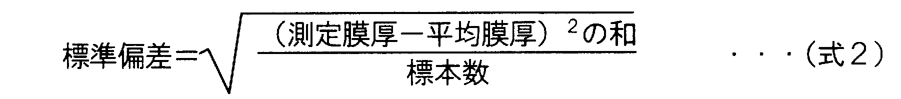
- the above measurement and analysis are performed with accuracy of 0.1 nanometers or more on the five ridges of the pleated structure, and the average film thickness and the standard deviation of the film thickness are three significant digits from Equation 1 and Equation 2, respectively. Calculated.
- Average film thickness Sum of measured film thickness / Number of specimens (Equation 1)
- membrane filtration treatment was performed by supplying a composite semipermeable membrane with a sodium chloride aqueous solution adjusted to a concentration of 2000 ppm, a temperature of 25 ° C., and a pH of 7 at an operating pressure of 1.55 MPa. This was determined by measuring the quality of the permeated water and the feed water after that time.
- Desalination rate 100 ⁇ ⁇ 1- (Salt concentration in permeated water / Salt concentration in feed water) ⁇ (%) (Membrane permeation flux) From the amount of the membrane permeated water and the area of the composite semipermeable membrane, the amount of water per day per square meter of membrane area, that is, the membrane permeation flux (m 3 / m 2 / day) was determined.
- a polyester nonwoven fabric (air permeability: 0.5 to 1 cc / cm 2 / sec) was used as a base material.
- a 15.7 wt% DMF solution of polysulfone was prepared.
- a polysulfone solution was cast on a substrate with a thickness of 200 ⁇ m at room temperature (25 ° C.), and immediately immersed in pure water and allowed to stand for 5 minutes to prepare a microporous support membrane (thickness 210 to 215 ⁇ m).
- Reference Example 2 The same polyester nonwoven fabric as in Reference Example 1 was used as the substrate.
- the first polysulfone solution and the second polysulfone solution are simultaneously discharged, and the first polysulfone solution is placed on the substrate, and the second polysulfone solution is placed on the first polysulfone solution.
- the first polysulfone solution was cast so that the thickness of the first polysulfone solution was 180 ⁇ m and the thickness of the second polysulfone solution was 20 ⁇ m, and immediately immersed in pure water and allowed to stand for 5 minutes to prepare a microporous support membrane.
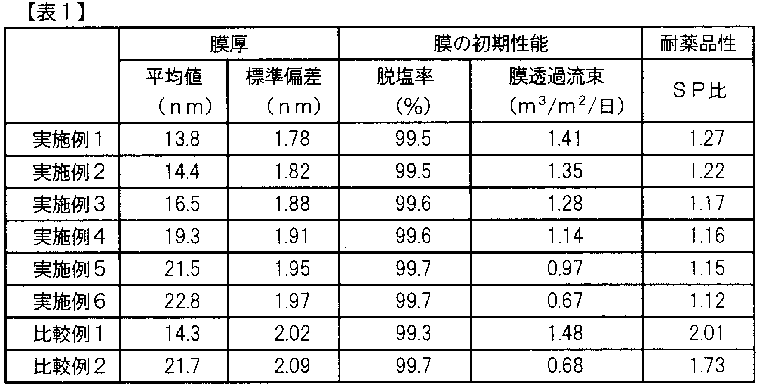
- Example 1 After applying a 2.0% by weight aqueous solution of m-PDA to the microporous support membrane obtained in Reference Example 2 and allowing it to stand for 2 minutes, nitrogen was blown from an air nozzle to remove excess from the surface of the microporous support membrane. The aqueous solution was removed. Subsequently, an n-decane solution containing 0.07% by weight of trimesic acid chloride is applied thereon so that the surface is completely wetted, and is allowed to stand for 10 seconds, and then the excess solution is removed from the film. The membrane was drained by holding vertically for 1 minute. The membrane thus obtained was washed with hot water at 90 ° C. for 2 minutes to obtain a composite semipermeable membrane. With respect to the obtained composite semipermeable membrane, the average thickness of the separation functional layer, the standard deviation of the thickness, the membrane performance, and the chemical resistance were as shown in Table 1, respectively.
- Example 2 A composite semipermeable membrane was obtained in the same manner as in Example 1 except that the concentration of the m-PDA aqueous solution was 2.2 wt% and the concentration of the trimesic acid chloride solution was 0.08 wt%. With respect to the obtained composite semipermeable membrane, the average thickness of the separation functional layer, the standard deviation of the thickness, the membrane performance, and the chemical resistance were as shown in Table 1, respectively.
- Example 3 A composite semipermeable membrane was obtained in the same manner as in Example 1 except that the concentration of the m-PDA aqueous solution was 2.4% by weight and the concentration of the trimesic acid chloride solution was 0.08% by weight. With respect to the obtained composite semipermeable membrane, the average thickness of the separation functional layer, the standard deviation of the thickness, the membrane performance, and the chemical resistance were as shown in Table 1, respectively.
- Example 4 A composite semipermeable membrane was obtained in the same manner as in Example 1 except that the concentration of the m-PDA aqueous solution was 2.8% by weight and the concentration of the trimesic acid chloride solution was 0.1% by weight. With respect to the obtained composite semipermeable membrane, the average thickness of the separation functional layer, the standard deviation of the thickness, the membrane performance, and the chemical resistance were as shown in Table 1, respectively.
- Example 5 A composite semipermeable membrane was obtained in the same manner as in Example 1 except that the concentration of the m-PDA aqueous solution was 3.0 wt% and the concentration of the trimesic acid chloride solution was 0.1 wt%. With respect to the obtained composite semipermeable membrane, the average thickness of the separation functional layer, the standard deviation of the thickness, the membrane performance, and the chemical resistance were as shown in Table 1, respectively.
- Example 6 A composite semipermeable membrane was obtained in the same manner as in Example 1, except that the concentration of the m-PDA aqueous solution was 3.2 wt% and the concentration of the trimesic acid chloride solution was 0.11 wt%. With respect to the obtained composite semipermeable membrane, the average thickness of the separation functional layer, the standard deviation of the thickness, the membrane performance, and the chemical resistance were as shown in Table 1, respectively.
- Comparative Example 2 A composite semipermeable membrane was obtained in the same manner as in Comparative Example 1, except that the concentration of the m-PDA aqueous solution was 3.0 wt% and the concentration of the trimesic acid chloride solution was 0.1 wt%. With respect to the obtained composite semipermeable membrane, the average thickness of the separation functional layer, the standard deviation of the thickness, the membrane performance, and the chemical resistance were as shown in Table 1, respectively.
- the composite semipermeable membranes having a standard deviation of the separation functional layer thickness of 2.00 nm or less the composite semipermeable membranes of Examples 2 to 5 in which the average thickness of the separation functional layer is 14 nm or more and 22 nm or less, Among them, the composite semipermeable membranes of Examples 3 and 4 in which the average thickness of the separation functional layer is 16 nm or more and 20 nm or less are higher in water permeability and higher chemical resistance than the composite semipermeable membranes of Examples 1 and 6. It turns out that it has sex.
- the composite semipermeable membrane of the present invention can be suitably used particularly for brine or seawater desalination.
Landscapes
- Chemical & Material Sciences (AREA)
- Chemical Kinetics & Catalysis (AREA)
- Dispersion Chemistry (AREA)
- Engineering & Computer Science (AREA)
- Manufacturing & Machinery (AREA)
- Separation Using Semi-Permeable Membranes (AREA)
Abstract
Description
(1)基材と多孔性支持体とからなる微多孔性支持膜上にポリアミド分離機能層が形成された複合半透膜であって、該分離機能層の膜厚の標準偏差が2.00nm以下である複合半透膜。
(2)該分離機能層の平均膜厚が14nm以上22nm以下である(1)に記載の複合半透膜。
(3)該多孔性支持体が多層構造を有する(1)または(2)に記載の複合半透膜。
(4)(1)~(3)のいずれかに記載の複合半透膜、原水流路材および透過水流路材が、多数の孔を穿設した筒状の集水管の周りに巻回された、スパイラル型の複合半透膜エレメント。
(5)基材と多孔性支持体とからなる微多孔性支持膜上にポリアミド分離機能層が形成された複合半透膜の製造方法であって、第1の層を形成する高分子溶液Aと第2の層を形成する高分子溶液Bを、同時に基材上に塗布した後、非溶媒中に浸漬して、高分子溶液Aおよび高分子溶液Bを凝固させて多孔性支持体を形成する工程、および、つづいて該多孔性支持体上に分離機能層を形成する工程を含み、該第1の層は基材と接触するように形成され、該第2の層は分離機能層と接触するように形成され、かつ、該高分子溶液Bの高分子濃度が、該高分子溶液Aの高分子濃度よりも大きい複合半透膜の製造方法。

本発明の複合半透膜を構成する微多孔性支持膜は、基材上に、多孔性支持体を形成するための高分子溶液を塗布し、凝固させることにより形成される。
複合半透膜をPVAで包埋した後、四酸化オスミウムで染色して測定サンプルとした。得られたサンプルをTEMトモグラフィーを用いて撮影し、得られた3D画像を解析ソフトにより解析した。TEMトモグラフィー分析には、日本電子製電界放出型分析電子顕微鏡JEM2100Fを用いた。30万倍の倍率での取得画像を用いて、ひだ状構造の外部表面上のある点から内部表面への最短距離を膜厚とし、ひだ状構造の凸部1個に対し、50箇所の点について解析を行った。ひだ状構造の凸部5個に対して0.1ナノメートル以上の精度で上記の測定および解析を行い、平均膜厚および膜厚の標準偏差をそれぞれ式1および式2より有効数字3桁で算出した。
脱塩率=100×{1-(透過水中の塩濃度/供給水中の塩濃度)} (%)
(膜透過流束)
供給水の膜透過水量と複合半透膜の面積から、膜面積1平方メートルあたり、1日あたりの透水量、すなわち膜透過流束(m3/m2/日)を求めた。
複合半透膜をpH13の水酸化ナトリウム水溶液とpH1の硫酸水溶液とにそれぞれ1時間ずつ室温で浸漬する操作を20サイクル繰り返し、その前後での脱塩率の変化により、耐薬品性を評価した。
SP比=(100-浸漬後の脱塩率)/(100-浸漬前の脱塩率)
なお、SPとはSubstance Peameation:物質透過の略である。
ポリエステル不織布(通気度0.5~1cc/cm2/sec)を基材として用いた。多孔性支持体形成用の溶液として、ポリスルホンの15.7重量%DMF溶液を調製した。基材上にポリスルホン溶液を200μmの厚みで室温(25℃)でキャストし、ただちに純水中に浸漬して5分間放置することによって微多孔性支持膜(厚さ210~215μm)を作製した。
参考例1と同様のポリエステル不織布を基材として用いた。第1のポリスルホン溶液(14.0重量%DMF溶液)と第2のポリスルホン溶液(17.0重量%DMF溶液)を調製した。二重スリットダイコーターを用いて、第1のポリスルホン溶液および第2のポリスルホン溶液を同時に吐出し、基材上に第1のポリスルホン溶液を、第1のポリスルホン溶液の上に第2のポリスルホン溶液をキャストした。第1のポリスルホン溶液の厚みが180μm、第2のポリスルホン溶液の厚みが20μmとなるようにキャストし、ただちに純水中に浸漬して5分間放置することによって微多孔性支持膜を作製した。
参考例2で得られた微多孔性支持膜に、m-PDAの2.0重量%水溶液を塗布して2分間静置した後、エアーノズルから窒素を吹き付けて微多孔性支持膜表面から余分な水溶液を取り除いた。続いて、その上に、トリメシン酸クロリド0.07重量%を含むn-デカン溶液を、表面が完全に濡れるように塗布して10秒間静置した後、膜から余分な溶液を除去するために膜を1分間垂直に保持して液切りした。このようにして得られた膜を、90℃の熱水で2分間洗浄して、複合半透膜を得た。得られた複合半透膜について、分離機能層の平均膜厚、膜厚の標準偏差、膜性能および耐薬品性はそれぞれ表1に示す通りであった。
m-PDA水溶液の濃度を2.2重量%、トリメシン酸クロリド溶液の濃度を0.08重量%としたこと以外は実施例1と同様の方法により複合半透膜を得た。得られた複合半透膜について、分離機能層の平均膜厚、膜厚の標準偏差、膜性能および耐薬品性はそれぞれ表1に示す通りであった。
m-PDA水溶液の濃度を2.4重量%、トリメシン酸クロリド溶液の濃度を0.08重量%としたこと以外は実施例1と同様の方法により複合半透膜を得た。得られた複合半透膜について、分離機能層の平均膜厚、膜厚の標準偏差、膜性能および耐薬品性はそれぞれ表1に示す通りであった。
m-PDA水溶液の濃度を2.8重量%、トリメシン酸クロリド溶液の濃度を0.1重量%としたこと以外は実施例1と同様の方法により複合半透膜を得た。得られた複合半透膜について、分離機能層の平均膜厚、膜厚の標準偏差、膜性能および耐薬品性はそれぞれ表1に示す通りであった。
m-PDA水溶液の濃度を3.0重量%、トリメシン酸クロリド溶液の濃度を0.1重量%としたこと以外は実施例1と同様の方法により複合半透膜を得た。得られた複合半透膜について、分離機能層の平均膜厚、膜厚の標準偏差、膜性能および耐薬品性はそれぞれ表1に示す通りであった。
m-PDA水溶液の濃度を3.2重量%、トリメシン酸クロリド溶液の濃度を0.11重量%としたこと以外は実施例1と同様の方法により複合半透膜を得た。得られた複合半透膜について、分離機能層の平均膜厚、膜厚の標準偏差、膜性能および耐薬品性はそれぞれ表1に示す通りであった。
参考例1で得られた微多孔性支持膜に、m-PDAの2.2重量%水溶液を塗布して2分間静置した後、エアーノズルから窒素を吹き付けて微多孔性支持膜表面から余分な水溶液を取り除いた。続いて、その上に、トリメシン酸クロリド0.08重量%を含むn-デカン溶液を表面が完全に濡れるように塗布して10秒間静置した後、膜から余分な溶液を除去するために膜を1分間垂直に保持して液切りした。このようにして得られた膜を、90℃の熱水で2分間洗浄して複合半透膜を得た。得られた複合半透膜について、分離機能層の平均膜厚、膜厚の標準偏差、膜性能および耐薬品性はそれぞれ表1に示す通りであった。
m-PDA水溶液の濃度を3.0重量%、トリメシン酸クロリド溶液の濃度を0.1重量%としたこと以外は比較例1と同様の方法により複合半透膜を得た。得られた複合半透膜について、分離機能層の平均膜厚、膜厚の標準偏差、膜性能および耐薬品性はそれぞれ表1に示す通りであった。
Claims (5)
- 基材と多孔性支持体とからなる微多孔性支持膜上にポリアミド分離機能層が形成された複合半透膜であって、該分離機能層の膜厚の標準偏差が2.00nm以下である複合半透膜。
- 該分離機能層の平均膜厚が14nm以上22nm以下である請求項1に記載の複合半透膜。
- 該多孔性支持体が多層構造を有する請求項1または2に記載の複合半透膜。
- 請求項1~3のいずれかに記載の複合半透膜、原水流路材および透過水流路材が、多数の孔を穿設した筒状の集水管の周りに巻回された、スパイラル型の複合半透膜エレメント。
- 基材と多孔性支持体とからなる微多孔性支持膜上にポリアミド分離機能層が形成された複合半透膜の製造方法であって、第1の層を形成する高分子溶液Aと第2の層を形成する高分子溶液Bを、同時に基材上に塗布した後、非溶媒中に浸漬して、高分子溶液Aおよび高分子溶液Bを凝固させて多孔性支持体を形成する工程、および、つづいて該多孔性支持体上に分離機能層を形成する工程を含み、該第1の層は基材と接触するように形成され、該第2の層は分離機能層と接触するように形成され、かつ、該高分子溶液Bの高分子濃度が、該高分子溶液Aの高分子濃度よりも大きい複合半透膜の製造方法。
Priority Applications (7)
| Application Number | Priority Date | Filing Date | Title |
|---|---|---|---|
| EP12768506.3A EP2695670B1 (en) | 2011-04-01 | 2012-03-28 | Composite semipermeable membrane, composite semipermeable membrane element, and method for manufacturing composite semipermeable membrane |
| KR1020187032514A KR101985351B1 (ko) | 2011-04-01 | 2012-03-28 | 복합 반투막, 복합 반투막 엘리먼트 및 복합 반투막의 제조 방법 |
| KR1020137022085A KR20140016271A (ko) | 2011-04-01 | 2012-03-28 | 복합 반투막, 복합 반투막 엘리먼트 및 복합 반투막의 제조 방법 |
| US14/009,285 US20140183127A1 (en) | 2011-04-01 | 2012-03-28 | Composite semipermeable membrane, composite semipermeable membrane element, and method for manufacturing composite semipermeable membrane |
| JP2012526766A JP5978998B2 (ja) | 2011-04-01 | 2012-03-28 | 複合半透膜、複合半透膜エレメントおよび複合半透膜の製造方法 |
| CN201280016823.2A CN103492060B (zh) | 2011-04-01 | 2012-03-28 | 复合半透膜、复合半透膜元件以及复合半透膜的制造方法 |
| US16/182,957 US20190070569A1 (en) | 2011-04-01 | 2018-11-07 | Composite semipermeable membrane, composite semipermeable membrane element, and method of manufacturing composite semipermeable membrane |
Applications Claiming Priority (2)
| Application Number | Priority Date | Filing Date | Title |
|---|---|---|---|
| JP2011-081618 | 2011-04-01 | ||
| JP2011081618 | 2011-04-01 |
Related Child Applications (2)
| Application Number | Title | Priority Date | Filing Date |
|---|---|---|---|
| US14/009,285 A-371-Of-International US20140183127A1 (en) | 2011-04-01 | 2012-03-28 | Composite semipermeable membrane, composite semipermeable membrane element, and method for manufacturing composite semipermeable membrane |
| US16/182,957 Division US20190070569A1 (en) | 2011-04-01 | 2018-11-07 | Composite semipermeable membrane, composite semipermeable membrane element, and method of manufacturing composite semipermeable membrane |
Publications (1)
| Publication Number | Publication Date |
|---|---|
| WO2012137635A1 true WO2012137635A1 (ja) | 2012-10-11 |
Family
ID=46969036
Family Applications (1)
| Application Number | Title | Priority Date | Filing Date |
|---|---|---|---|
| PCT/JP2012/058049 Ceased WO2012137635A1 (ja) | 2011-04-01 | 2012-03-28 | 複合半透膜、複合半透膜エレメントおよび複合半透膜の製造方法 |
Country Status (6)
| Country | Link |
|---|---|
| US (2) | US20140183127A1 (ja) |
| EP (1) | EP2695670B1 (ja) |
| JP (1) | JP5978998B2 (ja) |
| KR (2) | KR20140016271A (ja) |
| CN (1) | CN103492060B (ja) |
| WO (1) | WO2012137635A1 (ja) |
Cited By (6)
| Publication number | Priority date | Publication date | Assignee | Title |
|---|---|---|---|---|
| WO2014050701A1 (ja) * | 2012-09-26 | 2014-04-03 | 東レ株式会社 | 複合半透膜 |
| JP2014144441A (ja) * | 2013-01-30 | 2014-08-14 | Toray Ind Inc | 複合半透膜 |
| WO2014208603A1 (ja) * | 2013-06-28 | 2014-12-31 | 東レ株式会社 | 複合分離膜および分離膜エレメント |
| JP2015515372A (ja) * | 2012-04-09 | 2015-05-28 | スリーエム イノベイティブ プロパティズ カンパニー | 薄フィルム複合膜構造 |
| JPWO2016021731A1 (ja) * | 2014-08-08 | 2017-07-13 | 東レ株式会社 | 耐溶剤性分離膜 |
| EP3085435A4 (en) * | 2013-12-16 | 2017-10-11 | Toray Industries, Inc. | Semipermeable membrane manufacturing method and semipermeable membrane |
Families Citing this family (14)
| Publication number | Priority date | Publication date | Assignee | Title |
|---|---|---|---|---|
| JP6146303B2 (ja) * | 2012-01-16 | 2017-06-14 | 東レ株式会社 | 複合半透膜およびその製造方法 |
| JP6237232B2 (ja) | 2012-06-27 | 2017-11-29 | 東レ株式会社 | 複合半透膜 |
| KR102293090B1 (ko) * | 2014-06-30 | 2021-08-25 | 도레이 카부시키가이샤 | 복합 반투막 |
| JP2016055219A (ja) * | 2014-09-05 | 2016-04-21 | 日東電工株式会社 | 複合半透膜、分離膜エレメント、及びその製造方法 |
| CN105032218B (zh) * | 2015-07-20 | 2017-11-03 | 四川大学 | 一种增强型耐溶剂聚芳硫醚砜中空纤维膜及其制备方法 |
| US12048903B2 (en) | 2016-09-12 | 2024-07-30 | Fluid Technology Solutions (Fts), Inc. | Thin films covalently bonded to cellulose ester membranes and methods of making the same |
| CN106552514A (zh) * | 2016-11-11 | 2017-04-05 | 北京碧水源膜科技有限公司 | 一种一体式智能净水龙头专用复合纳滤膜及其制备方法 |
| KR101997137B1 (ko) * | 2017-01-06 | 2019-07-08 | 한국화학연구원 | 붕소 제거능이 우수한 역삼투막 및 이의 제조방법 |
| CN109841781A (zh) * | 2017-11-27 | 2019-06-04 | 四川东邦碳纤维材料有限公司 | 一种电池隔膜的制备方法及其制备的电池隔膜 |
| CN108380047A (zh) * | 2018-02-01 | 2018-08-10 | 北京碧水源膜科技有限公司 | 具有离子选择性分离的氧化石墨烯复合纳滤膜及其制备方法 |
| KR102212128B1 (ko) * | 2018-05-10 | 2021-02-17 | 주식회사 엘지화학 | 역삼투막, 이의 제조방법 및 수처리 모듈 |
| CN109012188B (zh) * | 2018-09-09 | 2020-08-18 | 浙江奥氏环境科技有限公司 | 一种高通量聚四氟乙烯复合纳滤膜的制备方法 |
| JP7032460B2 (ja) * | 2020-01-28 | 2022-03-08 | 株式会社エフ・シー・シー | 濾過フィルタの製造方法 |
| JP7581642B2 (ja) * | 2020-03-30 | 2024-11-13 | 東洋紡株式会社 | ポリフェニレン系半透膜およびその製造方法 |
Citations (10)
| Publication number | Priority date | Publication date | Assignee | Title |
|---|---|---|---|---|
| JPH0278428A (ja) | 1988-06-07 | 1990-03-19 | Toray Ind Inc | 複合半透膜およびその製造方法 |
| JPH05111625A (ja) * | 1992-03-27 | 1993-05-07 | Kuraray Co Ltd | 複合中空糸分離膜 |
| JPH0919630A (ja) | 1995-07-05 | 1997-01-21 | Nitto Denko Corp | 高透過性複合逆浸透膜 |
| JP2006102624A (ja) | 2004-10-05 | 2006-04-20 | Nitto Denko Corp | 逆浸透膜及びその製造方法 |
| JP2006130497A (ja) * | 2004-10-04 | 2006-05-25 | Nitto Denko Corp | 複合逆浸透膜の製造方法 |
| JP2007090192A (ja) | 2005-09-28 | 2007-04-12 | Toray Ind Inc | 複合半透膜の処理方法および製造方法 |
| JP2008253906A (ja) * | 2007-04-03 | 2008-10-23 | Nitto Denko Corp | 乾燥複合半透膜 |
| JP2009262089A (ja) * | 2008-04-28 | 2009-11-12 | Toray Ind Inc | 複合半透膜の製造方法 |
| JP2010099549A (ja) * | 2008-10-21 | 2010-05-06 | Toray Ind Inc | 複合半透膜の製造方法 |
| JP2010234284A (ja) | 2009-03-31 | 2010-10-21 | Toray Ind Inc | 複合半透膜 |
Family Cites Families (13)
| Publication number | Priority date | Publication date | Assignee | Title |
|---|---|---|---|---|
| US3367504A (en) * | 1964-12-21 | 1968-02-06 | Gulf General Atomic Inc | Spirally wrapped reverse osmosis membrane cell |
| GB2064367B (en) * | 1979-12-04 | 1984-02-29 | Toray Industries | Semi-permeable composite membrane |
| JPS5959213A (ja) * | 1982-09-28 | 1984-04-05 | Teijin Ltd | 多孔質支持膜及びそれを用いた複合膜 |
| EP0306350B1 (en) * | 1987-09-04 | 1991-08-14 | Ngk Insulators, Ltd. | Honeycomb structure for fluid filtration |
| JP3006976B2 (ja) * | 1993-06-24 | 2000-02-07 | 日東電工株式会社 | 高透過性複合逆浸透膜の製造方法 |
| US6413070B1 (en) * | 1997-04-11 | 2002-07-02 | Cuno Incorporated | System for manufacturing reinforced three-zone microporous membrane |
| JP4284767B2 (ja) * | 1998-10-05 | 2009-06-24 | 東レ株式会社 | 複合半透膜およびそれを用いた造水方法、流体分離素子 |
| CN1195577C (zh) * | 1999-08-20 | 2005-04-06 | 旭化成制药株式会社 | 生理活性物质溶液用过滤膜 |
| US6994789B2 (en) * | 2000-08-07 | 2006-02-07 | Cuno Incorporated | Pre-metered, unsupported multilayer microporous membrane |
| AU2001283157B2 (en) * | 2000-08-07 | 2006-03-16 | 3M Innovative Properties Company | Unsupported multizone microporous membrane |
| US20070084788A1 (en) * | 2005-10-14 | 2007-04-19 | Millipore Corporation | Ultrafiltration membranes and methods of making and use of ultrafiltration membranes |
| US20090226813A1 (en) * | 2008-03-07 | 2009-09-10 | Kotaro Takita | Microporous Membrane, Battery Separator and Battery |
| JP5419076B2 (ja) * | 2008-05-15 | 2014-02-19 | 旭化成メディカル株式会社 | 血小板の誘導方法 |
-
2012
- 2012-03-28 JP JP2012526766A patent/JP5978998B2/ja active Active
- 2012-03-28 CN CN201280016823.2A patent/CN103492060B/zh active Active
- 2012-03-28 WO PCT/JP2012/058049 patent/WO2012137635A1/ja not_active Ceased
- 2012-03-28 EP EP12768506.3A patent/EP2695670B1/en active Active
- 2012-03-28 KR KR1020137022085A patent/KR20140016271A/ko not_active Ceased
- 2012-03-28 US US14/009,285 patent/US20140183127A1/en not_active Abandoned
- 2012-03-28 KR KR1020187032514A patent/KR101985351B1/ko active Active
-
2018
- 2018-11-07 US US16/182,957 patent/US20190070569A1/en not_active Abandoned
Patent Citations (10)
| Publication number | Priority date | Publication date | Assignee | Title |
|---|---|---|---|---|
| JPH0278428A (ja) | 1988-06-07 | 1990-03-19 | Toray Ind Inc | 複合半透膜およびその製造方法 |
| JPH05111625A (ja) * | 1992-03-27 | 1993-05-07 | Kuraray Co Ltd | 複合中空糸分離膜 |
| JPH0919630A (ja) | 1995-07-05 | 1997-01-21 | Nitto Denko Corp | 高透過性複合逆浸透膜 |
| JP2006130497A (ja) * | 2004-10-04 | 2006-05-25 | Nitto Denko Corp | 複合逆浸透膜の製造方法 |
| JP2006102624A (ja) | 2004-10-05 | 2006-04-20 | Nitto Denko Corp | 逆浸透膜及びその製造方法 |
| JP2007090192A (ja) | 2005-09-28 | 2007-04-12 | Toray Ind Inc | 複合半透膜の処理方法および製造方法 |
| JP2008253906A (ja) * | 2007-04-03 | 2008-10-23 | Nitto Denko Corp | 乾燥複合半透膜 |
| JP2009262089A (ja) * | 2008-04-28 | 2009-11-12 | Toray Ind Inc | 複合半透膜の製造方法 |
| JP2010099549A (ja) * | 2008-10-21 | 2010-05-06 | Toray Ind Inc | 複合半透膜の製造方法 |
| JP2010234284A (ja) | 2009-03-31 | 2010-10-21 | Toray Ind Inc | 複合半透膜 |
Non-Patent Citations (1)
| Title |
|---|
| See also references of EP2695670A4 |
Cited By (8)
| Publication number | Priority date | Publication date | Assignee | Title |
|---|---|---|---|---|
| JP2015515372A (ja) * | 2012-04-09 | 2015-05-28 | スリーエム イノベイティブ プロパティズ カンパニー | 薄フィルム複合膜構造 |
| WO2014050701A1 (ja) * | 2012-09-26 | 2014-04-03 | 東レ株式会社 | 複合半透膜 |
| JPWO2014050701A1 (ja) * | 2012-09-26 | 2016-08-22 | 東レ株式会社 | 複合半透膜 |
| US9827536B2 (en) | 2012-09-26 | 2017-11-28 | Toray Industries, Inc. | Composite semipermeable membrane |
| JP2014144441A (ja) * | 2013-01-30 | 2014-08-14 | Toray Ind Inc | 複合半透膜 |
| WO2014208603A1 (ja) * | 2013-06-28 | 2014-12-31 | 東レ株式会社 | 複合分離膜および分離膜エレメント |
| EP3085435A4 (en) * | 2013-12-16 | 2017-10-11 | Toray Industries, Inc. | Semipermeable membrane manufacturing method and semipermeable membrane |
| JPWO2016021731A1 (ja) * | 2014-08-08 | 2017-07-13 | 東レ株式会社 | 耐溶剤性分離膜 |
Also Published As
| Publication number | Publication date |
|---|---|
| EP2695670B1 (en) | 2020-04-29 |
| US20140183127A1 (en) | 2014-07-03 |
| US20190070569A1 (en) | 2019-03-07 |
| KR20180124151A (ko) | 2018-11-20 |
| EP2695670A1 (en) | 2014-02-12 |
| EP2695670A4 (en) | 2015-05-27 |
| CN103492060A (zh) | 2014-01-01 |
| CN103492060B (zh) | 2016-03-30 |
| JPWO2012137635A1 (ja) | 2014-07-28 |
| KR20140016271A (ko) | 2014-02-07 |
| JP5978998B2 (ja) | 2016-08-24 |
| KR101985351B1 (ko) | 2019-06-03 |
Similar Documents
| Publication | Publication Date | Title |
|---|---|---|
| JP5978998B2 (ja) | 複合半透膜、複合半透膜エレメントおよび複合半透膜の製造方法 | |
| JP6197649B2 (ja) | 複合半透膜 | |
| JP6146303B2 (ja) | 複合半透膜およびその製造方法 | |
| JP6052172B2 (ja) | 複合半透膜の製造方法 | |
| JP6237232B2 (ja) | 複合半透膜 | |
| KR20110089254A (ko) | 복합 반투막 및 그의 제조 방법 | |
| JP2018039003A (ja) | 複合半透膜およびその製造方法 | |
| WO2014133133A1 (ja) | 複合半透膜 | |
| JP2019098330A (ja) | 複合半透膜およびその製造方法 | |
| JP6237233B2 (ja) | 複合半透膜および複合半透膜エレメント | |
| JP2014065004A (ja) | 複合半透膜 | |
| WO2016052427A1 (ja) | 複合半透膜及びその製造方法、スパイラル型分離膜エレメント | |
| JP2009226320A (ja) | 複合半透膜およびその製造方法 | |
| JP2014065003A (ja) | 複合半透膜及びその膜を用いた造水方法 | |
| JP2013223861A (ja) | 複合半透膜 | |
| WO2017057378A1 (ja) | 複合半透膜 | |
| JP2014188407A (ja) | 複合半透膜 | |
| JP2015123394A (ja) | 複合半透膜およびその製造方法 | |
| JP2014064989A (ja) | 複合半透膜 | |
| JP2025126116A (ja) | 複合半透膜 | |
| JP2014151241A (ja) | 複合半透膜およびその製造方法 | |
| JP2011255306A (ja) | 複合半透膜及びその製造方法 | |
| JP2018069148A (ja) | 複合半透膜およびその製造方法 |
Legal Events
| Date | Code | Title | Description |
|---|---|---|---|
| WWE | Wipo information: entry into national phase |
Ref document number: 201280016823.2 Country of ref document: CN |
|
| ENP | Entry into the national phase |
Ref document number: 2012526766 Country of ref document: JP Kind code of ref document: A |
|
| 121 | Ep: the epo has been informed by wipo that ep was designated in this application |
Ref document number: 12768506 Country of ref document: EP Kind code of ref document: A1 |
|
| ENP | Entry into the national phase |
Ref document number: 20137022085 Country of ref document: KR Kind code of ref document: A |
|
| NENP | Non-entry into the national phase |
Ref country code: DE |
|
| WWE | Wipo information: entry into national phase |
Ref document number: 14009285 Country of ref document: US |
|
| WWE | Wipo information: entry into national phase |
Ref document number: 2012768506 Country of ref document: EP |