WO2012153830A1 - Dispositif de passage de la marche arrière dans une boîte de vitesses - Google Patents
Dispositif de passage de la marche arrière dans une boîte de vitesses Download PDFInfo
- Publication number
- WO2012153830A1 WO2012153830A1 PCT/JP2012/062102 JP2012062102W WO2012153830A1 WO 2012153830 A1 WO2012153830 A1 WO 2012153830A1 JP 2012062102 W JP2012062102 W JP 2012062102W WO 2012153830 A1 WO2012153830 A1 WO 2012153830A1
- Authority
- WO
- WIPO (PCT)
- Prior art keywords
- reverse
- fork
- gear
- transmission
- arm
- Prior art date
- Legal status (The legal status is an assumption and is not a legal conclusion. Google has not performed a legal analysis and makes no representation as to the accuracy of the status listed.)
- Ceased
Links
Images





Classifications
-
- F—MECHANICAL ENGINEERING; LIGHTING; HEATING; WEAPONS; BLASTING
- F16—ENGINEERING ELEMENTS AND UNITS; GENERAL MEASURES FOR PRODUCING AND MAINTAINING EFFECTIVE FUNCTIONING OF MACHINES OR INSTALLATIONS; THERMAL INSULATION IN GENERAL
- F16H—GEARING
- F16H3/00—Toothed gearings for conveying rotary motion with variable gear ratio or for reversing rotary motion
- F16H3/02—Toothed gearings for conveying rotary motion with variable gear ratio or for reversing rotary motion without gears having orbital motion
- F16H3/08—Toothed gearings for conveying rotary motion with variable gear ratio or for reversing rotary motion without gears having orbital motion exclusively or essentially with continuously meshing gears, that can be disengaged from their shafts
- F16H3/087—Toothed gearings for conveying rotary motion with variable gear ratio or for reversing rotary motion without gears having orbital motion exclusively or essentially with continuously meshing gears, that can be disengaged from their shafts characterised by the disposition of the gears
- F16H3/091—Toothed gearings for conveying rotary motion with variable gear ratio or for reversing rotary motion without gears having orbital motion exclusively or essentially with continuously meshing gears, that can be disengaged from their shafts characterised by the disposition of the gears including a single countershaft
-
- F—MECHANICAL ENGINEERING; LIGHTING; HEATING; WEAPONS; BLASTING
- F16—ENGINEERING ELEMENTS AND UNITS; GENERAL MEASURES FOR PRODUCING AND MAINTAINING EFFECTIVE FUNCTIONING OF MACHINES OR INSTALLATIONS; THERMAL INSULATION IN GENERAL
- F16H—GEARING
- F16H3/00—Toothed gearings for conveying rotary motion with variable gear ratio or for reversing rotary motion
- F16H3/02—Toothed gearings for conveying rotary motion with variable gear ratio or for reversing rotary motion without gears having orbital motion
- F16H3/08—Toothed gearings for conveying rotary motion with variable gear ratio or for reversing rotary motion without gears having orbital motion exclusively or essentially with continuously meshing gears, that can be disengaged from their shafts
- F16H3/14—Gearings for reversal only
-
- F—MECHANICAL ENGINEERING; LIGHTING; HEATING; WEAPONS; BLASTING
- F16—ENGINEERING ELEMENTS AND UNITS; GENERAL MEASURES FOR PRODUCING AND MAINTAINING EFFECTIVE FUNCTIONING OF MACHINES OR INSTALLATIONS; THERMAL INSULATION IN GENERAL
- F16H—GEARING
- F16H63/00—Control outputs from the control unit to change-speed- or reversing-gearings for conveying rotary motion or to other devices than the final output mechanism
- F16H63/02—Final output mechanisms therefor; Actuating means for the final output mechanisms
- F16H63/30—Constructional features of the final output mechanisms
-
- F—MECHANICAL ENGINEERING; LIGHTING; HEATING; WEAPONS; BLASTING
- F16—ENGINEERING ELEMENTS AND UNITS; GENERAL MEASURES FOR PRODUCING AND MAINTAINING EFFECTIVE FUNCTIONING OF MACHINES OR INSTALLATIONS; THERMAL INSULATION IN GENERAL
- F16H—GEARING
- F16H63/00—Control outputs from the control unit to change-speed- or reversing-gearings for conveying rotary motion or to other devices than the final output mechanism
- F16H63/02—Final output mechanisms therefor; Actuating means for the final output mechanisms
- F16H63/30—Constructional features of the final output mechanisms
- F16H63/302—Final output mechanisms for reversing
-
- F—MECHANICAL ENGINEERING; LIGHTING; HEATING; WEAPONS; BLASTING
- F16—ENGINEERING ELEMENTS AND UNITS; GENERAL MEASURES FOR PRODUCING AND MAINTAINING EFFECTIVE FUNCTIONING OF MACHINES OR INSTALLATIONS; THERMAL INSULATION IN GENERAL
- F16H—GEARING
- F16H3/00—Toothed gearings for conveying rotary motion with variable gear ratio or for reversing rotary motion
- F16H3/02—Toothed gearings for conveying rotary motion with variable gear ratio or for reversing rotary motion without gears having orbital motion
- F16H3/08—Toothed gearings for conveying rotary motion with variable gear ratio or for reversing rotary motion without gears having orbital motion exclusively or essentially with continuously meshing gears, that can be disengaged from their shafts
- F16H3/087—Toothed gearings for conveying rotary motion with variable gear ratio or for reversing rotary motion without gears having orbital motion exclusively or essentially with continuously meshing gears, that can be disengaged from their shafts characterised by the disposition of the gears
- F16H3/091—Toothed gearings for conveying rotary motion with variable gear ratio or for reversing rotary motion without gears having orbital motion exclusively or essentially with continuously meshing gears, that can be disengaged from their shafts characterised by the disposition of the gears including a single countershaft
- F16H3/0915—Toothed gearings for conveying rotary motion with variable gear ratio or for reversing rotary motion without gears having orbital motion exclusively or essentially with continuously meshing gears, that can be disengaged from their shafts characterised by the disposition of the gears including a single countershaft with coaxial input and output shafts
-
- Y—GENERAL TAGGING OF NEW TECHNOLOGICAL DEVELOPMENTS; GENERAL TAGGING OF CROSS-SECTIONAL TECHNOLOGIES SPANNING OVER SEVERAL SECTIONS OF THE IPC; TECHNICAL SUBJECTS COVERED BY FORMER USPC CROSS-REFERENCE ART COLLECTIONS [XRACs] AND DIGESTS
- Y10—TECHNICAL SUBJECTS COVERED BY FORMER USPC
- Y10T—TECHNICAL SUBJECTS COVERED BY FORMER US CLASSIFICATION
- Y10T74/00—Machine element or mechanism
- Y10T74/19—Gearing
- Y10T74/19219—Interchangeably locked
- Y10T74/19233—Plurality of counter shafts
Definitions
- the transmission casing 10 of this transmission includes first and second casings 11 and 13 and a shift bracket 12 interposed between them in a liquid-tight manner.
- the bolts 13 to 13 are integrally bolted, and the interior thereof is separated into a first chamber S1 on the first casing 11 side and a second chamber S2 of the second casing 13.
- the three fork shafts 30 to 32 of the shift mechanism 29 are integrally provided with shift pieces 30a to 32a at one end, and stop rings 30c to 32c are located at the same distance from the end surfaces of the shift pieces 30a to 32a. It is locked.
- Each of the fork shafts 30 to 32 has a front end portion and a portion between each of the shift pieces 30a to 32a and each of the stop rings 30c to 32c at the same pitch and the same plane as the first casing 11 and the shift bracket 12 of the transmission casing 10.
- the support holes 11a to 11c and the holding holes 12a to 12c formed above are fitted to be slidable in the axial direction.
- the reverse fork operates one switching clutch mechanism that selectively switches power transmission between both shafts by any one of a plurality of pairs of transmission gears.
- the fork shaft is shifted from the neutral position to the direction in which the one switching clutch mechanism is operated, the fork shaft is not moved, but from the neutral position to the reverse shift position opposite to the aforementioned direction.
- it is connected so as to be moved together with the one fork shaft, and one switching clutch mechanism is shifted in any direction by one fork shaft, and the counter shaft and the output shaft at the beginning of the shift stroke.
- the hooking holes 53e and 55e are urged outward.
- Over mechanism JO is configured.
- the distance from the center of the support pin 54 has been described as that the hook hole 55e is separated from the hook hole 53e, but conversely, the distance from the center of the support pin 54 is The hooking hole 53e may be separated from the hooking hole 55e.
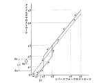
- FIG. 4 is a graph showing the characteristics of the idle gear stroke of the reverse gear train with respect to the reverse fork stroke of the embodiment described in FIGS. 1 to 3, and the broken line is a graph of the prior art described in FIGS.
- FIG. 6 is a diagram showing the characteristics of the idle gear stroke of the reverse gear train with respect to the reverse fork stroke.
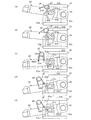
- FIGS. 5 and 6 are diagrams showing the operation of each member of the main part at each time point during the reverse shift and the reverse return shift in the embodiment shown in FIGS. First, the operation at the time of reverse shift in which the third fork shaft 32 moves from the neutral position to the reverse shift position will be described with reference to FIGS.
Landscapes
- Engineering & Computer Science (AREA)
- General Engineering & Computer Science (AREA)
- Mechanical Engineering (AREA)
- Gear-Shifting Mechanisms (AREA)
- Structure Of Transmissions (AREA)
Abstract
L'invention porte sur les boîtes de vitesses. Dans la présente invention, un bras de marche arrière (55) est entraîné en va-et-vient par le doigt menant (51c) d'une fourchette de marche arrière (51) qui est inséré dans un trou mené (55b) du bras de marche arrière, et un pignon fou (52) est déplacé dans la direction axiale par le bras de marche arrière et est mis en prise ou hors de prise entre un pignon mené (50c) et un pignon menant (50a) du train de marche arrière (50). Le diamètre extérieur du doigt menant (51c) est plus petit que la largeur comprise entre les deux surfaces latérales intérieures plates du trou mené du bras de marche arrière et, de cette façon, une fente est ménagée entre le doigt menant et le bras de marche arrière. Un mécanisme de bretelle (JO) qui sollicite élastiquement le bras de marche arrière vers l'extérieur en l'éloignant d'une limite qui est une position intermédiaire prédéterminée comprise dans la plage de mouvement alternatif du bras de marche arrière, est agencé entre le bras de marche arrière et un carter de boîte de vitesses (10), et amène le doigt menant à entrer en contact avec l'une des surfaces latérales intérieures du trou mené. Le résultat est qu'il est possible de réaliser un dispositif de passage de la marche arrière d'une boîte de vitesses qui déplace le pignon fou dans une direction linéaire, le dispositif de passage de la marche arrière assurant la solidité du pignon fou et garantissant qu'il ne se produit pas de bruit de pignon.
Priority Applications (3)
| Application Number | Priority Date | Filing Date | Title |
|---|---|---|---|
| US14/115,899 US9217491B2 (en) | 2011-05-11 | 2012-05-11 | Reverse shift device in transmission |
| CN201280022735.3A CN103518086B (zh) | 2011-05-11 | 2012-05-11 | 变速器的倒挡装置 |
| EP12782761.6A EP2708780B1 (fr) | 2011-05-11 | 2012-05-11 | Dispositif de passage de la marche arrière dans une boîte de vitesses |
Applications Claiming Priority (2)
| Application Number | Priority Date | Filing Date | Title |
|---|---|---|---|
| JP2011-106419 | 2011-05-11 | ||
| JP2011106419A JP5746555B2 (ja) | 2011-05-11 | 2011-05-11 | 変速機におけるリバースシフト装置 |
Publications (1)
| Publication Number | Publication Date |
|---|---|
| WO2012153830A1 true WO2012153830A1 (fr) | 2012-11-15 |
Family
ID=47139304
Family Applications (1)
| Application Number | Title | Priority Date | Filing Date |
|---|---|---|---|
| PCT/JP2012/062102 Ceased WO2012153830A1 (fr) | 2011-05-11 | 2012-05-11 | Dispositif de passage de la marche arrière dans une boîte de vitesses |
Country Status (5)
| Country | Link |
|---|---|
| US (1) | US9217491B2 (fr) |
| EP (1) | EP2708780B1 (fr) |
| JP (1) | JP5746555B2 (fr) |
| CN (1) | CN103518086B (fr) |
| WO (1) | WO2012153830A1 (fr) |
Cited By (3)
| Publication number | Priority date | Publication date | Assignee | Title |
|---|---|---|---|---|
| JP2014109280A (ja) * | 2012-11-30 | 2014-06-12 | Toyota Motor Corp | シフト装置 |
| US20140283641A1 (en) * | 2013-03-20 | 2014-09-25 | GM Global Technology Operations LLC | Gear engagement mechanism |
| CN104121360A (zh) * | 2013-04-28 | 2014-10-29 | 北汽福田汽车股份有限公司 | 手动档汽车防误挂倒档的自控系统及离合器总成 |
Families Citing this family (5)
| Publication number | Priority date | Publication date | Assignee | Title |
|---|---|---|---|---|
| JP5827883B2 (ja) * | 2011-12-14 | 2015-12-02 | ヤンマー株式会社 | 舶用減速逆転装置 |
| JP6154150B2 (ja) * | 2013-02-04 | 2017-06-28 | アイシン・エーアイ株式会社 | 走行変速装置 |
| WO2014132289A1 (fr) * | 2013-02-27 | 2014-09-04 | アイシン・エーアイ株式会社 | Transmission |
| CN105202136B (zh) * | 2015-09-24 | 2018-12-04 | 济南大学 | 新型传动锁定装置 |
| CN112431905B (zh) * | 2020-11-21 | 2022-04-15 | 东莞市赛仑特实业有限公司 | 一种可以正转反转切换的减速机 |
Citations (7)
| Publication number | Priority date | Publication date | Assignee | Title |
|---|---|---|---|---|
| JPS5989832A (ja) * | 1982-11-12 | 1984-05-24 | Nippon Kogaku Kk <Nikon> | 動力伝達切換装置 |
| JPS59189947U (ja) * | 1983-06-03 | 1984-12-17 | マツダ株式会社 | 自動車用歯車変速機のシフト装置 |
| JPH0196018U (fr) * | 1987-12-17 | 1989-06-26 | ||
| JPH11344116A (ja) * | 1998-06-03 | 1999-12-14 | Suzuki Motor Corp | 歯車変速機 |
| JP2010054942A (ja) | 2008-08-29 | 2010-03-11 | Canon Inc | 電子写真用シームレスベルト及びその製造方法 |
| JP2010216603A (ja) * | 2009-03-18 | 2010-09-30 | Aisin Ai Co Ltd | 手動変速機の操作装置 |
| JP2010266044A (ja) * | 2009-05-18 | 2010-11-25 | Toyota Motor Corp | 変速機の操作装置 |
Family Cites Families (14)
| Publication number | Priority date | Publication date | Assignee | Title |
|---|---|---|---|---|
| FR1409970A (fr) | 1964-08-21 | 1965-09-03 | Ford France | Boîte de vitesses à changements de rapports entièrement synchronisés |
| GB2136068B (en) * | 1983-03-04 | 1986-07-30 | Honda Motor Co Ltd | Multi-speed transmission |
| JPS59189947A (ja) | 1983-04-13 | 1984-10-27 | 大塚鉄工株式会社 | 粗粒炭及び微粉炭の同時製造方法及び設備 |
| JPH077652Y2 (ja) * | 1986-08-08 | 1995-02-22 | 本田技研工業株式会社 | 後進機構付き変速装置 |
| JP2522793B2 (ja) | 1987-05-08 | 1996-08-07 | 日産自動車株式会社 | 変速機の変速操作機構 |
| JPH0196018A (ja) | 1987-10-08 | 1989-04-14 | Lion Corp | 二酸化チタンの製造方法 |
| US5086896A (en) | 1989-11-30 | 1992-02-11 | Kabushiki Kaisha Kobe Seiko Sho | Jaw clutch coupling mechanism and shift lever link mechanism |
| JP3163874B2 (ja) * | 1993-09-30 | 2001-05-08 | スズキ株式会社 | 変速機のリバースギヤ鳴り防止装置 |
| US5445253A (en) * | 1994-02-16 | 1995-08-29 | Saturn Corporation | Shift control mechanism for a multi-speed countershaft transmission |
| JP3641839B2 (ja) | 1994-07-22 | 2005-04-27 | マツダ株式会社 | 歯車式変速機のリバース操作機構 |
| JP3552897B2 (ja) | 1998-01-27 | 2004-08-11 | ダイハツ工業株式会社 | 手動変速機のシフト装置 |
| CN2367809Y (zh) | 1998-09-30 | 2000-03-08 | 株洲市百川电器有限责任公司 | 扭簧支撑翻盖换气扇 |
| FR2924777B1 (fr) | 2007-12-11 | 2010-04-02 | Peugeot Citroen Automobiles Sa | Dispositif de commande interne de boite de vitesses |
| JP2011190820A (ja) | 2010-03-11 | 2011-09-29 | Aisin Ai Co Ltd | 変速機におけるリバースシフト装置 |
-
2011
- 2011-05-11 JP JP2011106419A patent/JP5746555B2/ja not_active Expired - Fee Related
-
2012
- 2012-05-11 EP EP12782761.6A patent/EP2708780B1/fr not_active Not-in-force
- 2012-05-11 WO PCT/JP2012/062102 patent/WO2012153830A1/fr not_active Ceased
- 2012-05-11 US US14/115,899 patent/US9217491B2/en not_active Expired - Fee Related
- 2012-05-11 CN CN201280022735.3A patent/CN103518086B/zh not_active Expired - Fee Related
Patent Citations (7)
| Publication number | Priority date | Publication date | Assignee | Title |
|---|---|---|---|---|
| JPS5989832A (ja) * | 1982-11-12 | 1984-05-24 | Nippon Kogaku Kk <Nikon> | 動力伝達切換装置 |
| JPS59189947U (ja) * | 1983-06-03 | 1984-12-17 | マツダ株式会社 | 自動車用歯車変速機のシフト装置 |
| JPH0196018U (fr) * | 1987-12-17 | 1989-06-26 | ||
| JPH11344116A (ja) * | 1998-06-03 | 1999-12-14 | Suzuki Motor Corp | 歯車変速機 |
| JP2010054942A (ja) | 2008-08-29 | 2010-03-11 | Canon Inc | 電子写真用シームレスベルト及びその製造方法 |
| JP2010216603A (ja) * | 2009-03-18 | 2010-09-30 | Aisin Ai Co Ltd | 手動変速機の操作装置 |
| JP2010266044A (ja) * | 2009-05-18 | 2010-11-25 | Toyota Motor Corp | 変速機の操作装置 |
Non-Patent Citations (1)
| Title |
|---|
| See also references of EP2708780A4 * |
Cited By (4)
| Publication number | Priority date | Publication date | Assignee | Title |
|---|---|---|---|---|
| JP2014109280A (ja) * | 2012-11-30 | 2014-06-12 | Toyota Motor Corp | シフト装置 |
| US20140283641A1 (en) * | 2013-03-20 | 2014-09-25 | GM Global Technology Operations LLC | Gear engagement mechanism |
| US9347549B2 (en) * | 2013-03-20 | 2016-05-24 | Gm Global Technology Operations, Llc | Gear engagement mechanism |
| CN104121360A (zh) * | 2013-04-28 | 2014-10-29 | 北汽福田汽车股份有限公司 | 手动档汽车防误挂倒档的自控系统及离合器总成 |
Also Published As
| Publication number | Publication date |
|---|---|
| US9217491B2 (en) | 2015-12-22 |
| EP2708780A1 (fr) | 2014-03-19 |
| CN103518086A (zh) | 2014-01-15 |
| EP2708780B1 (fr) | 2015-11-25 |
| US20140123792A1 (en) | 2014-05-08 |
| CN103518086B (zh) | 2016-04-20 |
| EP2708780A4 (fr) | 2014-12-17 |
| JP2012237367A (ja) | 2012-12-06 |
| JP5746555B2 (ja) | 2015-07-08 |
Similar Documents
| Publication | Publication Date | Title |
|---|---|---|
| JP5746555B2 (ja) | 変速機におけるリバースシフト装置 | |
| CN101398079B (zh) | 双离合器式变速装置 | |
| JP5146253B2 (ja) | 手動変速機 | |
| CN101418855B (zh) | 用于手动变速器的齿轮噪声防止系统 | |
| JP4270334B2 (ja) | 車両用常時噛み合い式変速装置 | |
| CN103562601B (zh) | 车辆用手动变速器的操作机构 | |
| JP5874651B2 (ja) | 手動変速機 | |
| CN103671873A (zh) | 用于机动车辆的变速箱的档位的选择和接合的装置 | |
| JP4596015B2 (ja) | 手動変速機のギヤ鳴り防止装置 | |
| JP2004044648A (ja) | 変速機 | |
| EP2107279B1 (fr) | Transmission manuelle comprenant un dispositif de prévention du bruit d'engrenage | |
| JPH06159389A (ja) | 変速機の同期装置 | |
| JP2011190820A (ja) | 変速機におけるリバースシフト装置 | |
| JP2696630B2 (ja) | 手動変速機のギヤ鳴り防止機構 | |
| JP2005155800A (ja) | リバースシフトのギヤ鳴き防止機構 | |
| JP4659869B2 (ja) | 変速機およびその製造方法 | |
| CN210531590U (zh) | 换挡机构及具有其的全地形车 | |
| CN110319159B (zh) | 变速装置 | |
| JP3552897B2 (ja) | 手動変速機のシフト装置 | |
| JP6350610B2 (ja) | 変速機の変速操作機構 | |
| JP2008075672A (ja) | 変速機 | |
| JP3511671B2 (ja) | 変速機のリバースギヤ鳴り防止装置 | |
| JP2012149671A (ja) | 変速機のシフトストッパ構造 | |
| JPH06341548A (ja) | 変速機のリバースギヤ鳴り防止装置 | |
| JP6038176B2 (ja) | 変速操作装置 |
Legal Events
| Date | Code | Title | Description |
|---|---|---|---|
| WWE | Wipo information: entry into national phase |
Ref document number: 201280022735.3 Country of ref document: CN |
|
| 121 | Ep: the epo has been informed by wipo that ep was designated in this application |
Ref document number: 12782761 Country of ref document: EP Kind code of ref document: A1 |
|
| WWE | Wipo information: entry into national phase |
Ref document number: 14115899 Country of ref document: US |
|
| NENP | Non-entry into the national phase |
Ref country code: DE |
|
| WWE | Wipo information: entry into national phase |
Ref document number: 2012782761 Country of ref document: EP |