WO2012164894A1 - 電気式暖房装置および電気自動車 - Google Patents
電気式暖房装置および電気自動車 Download PDFInfo
- Publication number
- WO2012164894A1 WO2012164894A1 PCT/JP2012/003432 JP2012003432W WO2012164894A1 WO 2012164894 A1 WO2012164894 A1 WO 2012164894A1 JP 2012003432 W JP2012003432 W JP 2012003432W WO 2012164894 A1 WO2012164894 A1 WO 2012164894A1
- Authority
- WO
- WIPO (PCT)
- Prior art keywords
- heating device
- stator
- rotor
- electric heating
- group
- Prior art date
- Legal status (The legal status is an assumption and is not a legal conclusion. Google has not performed a legal analysis and makes no representation as to the accuracy of the status listed.)
- Ceased
Links
Images

Classifications
-
- F—MECHANICAL ENGINEERING; LIGHTING; HEATING; WEAPONS; BLASTING
- F24—HEATING; RANGES; VENTILATING
- F24H—FLUID HEATERS, e.g. WATER OR AIR HEATERS, HAVING HEAT-GENERATING MEANS, e.g. HEAT PUMPS, IN GENERAL
- F24H3/00—Air heaters
- F24H3/02—Air heaters with forced circulation
- F24H3/04—Air heaters with forced circulation the air being in direct contact with the heating medium, e.g. electric heating element
- F24H3/0405—Air heaters with forced circulation the air being in direct contact with the heating medium, e.g. electric heating element using electric energy supply, e.g. the heating medium being a resistive element; Heating by direct contact, i.e. with resistive elements, electrodes and fins being bonded together without additional element in-between
- F24H3/0429—For vehicles
-
- B—PERFORMING OPERATIONS; TRANSPORTING
- B60—VEHICLES IN GENERAL
- B60H—ARRANGEMENTS OF HEATING, COOLING, VENTILATING OR OTHER AIR-TREATING DEVICES SPECIALLY ADAPTED FOR PASSENGER OR GOODS SPACES OF VEHICLES
- B60H1/00—Heating, cooling or ventilating devices
- B60H1/22—Heating, cooling or ventilating devices the heat source being other than the propulsion plant
-
- B—PERFORMING OPERATIONS; TRANSPORTING
- B60—VEHICLES IN GENERAL
- B60H—ARRANGEMENTS OF HEATING, COOLING, VENTILATING OR OTHER AIR-TREATING DEVICES SPECIALLY ADAPTED FOR PASSENGER OR GOODS SPACES OF VEHICLES
- B60H1/00—Heating, cooling or ventilating devices
- B60H1/22—Heating, cooling or ventilating devices the heat source being other than the propulsion plant
- B60H1/2215—Heating, cooling or ventilating devices the heat source being other than the propulsion plant the heat being derived from electric heaters
-
- B—PERFORMING OPERATIONS; TRANSPORTING
- B60—VEHICLES IN GENERAL
- B60H—ARRANGEMENTS OF HEATING, COOLING, VENTILATING OR OTHER AIR-TREATING DEVICES SPECIALLY ADAPTED FOR PASSENGER OR GOODS SPACES OF VEHICLES
- B60H1/00—Heating, cooling or ventilating devices
- B60H1/22—Heating, cooling or ventilating devices the heat source being other than the propulsion plant
- B60H1/2215—Heating, cooling or ventilating devices the heat source being other than the propulsion plant the heat being derived from electric heaters
- B60H1/2225—Heating, cooling or ventilating devices the heat source being other than the propulsion plant the heat being derived from electric heaters arrangements of electric heaters for heating air
-
- F—MECHANICAL ENGINEERING; LIGHTING; HEATING; WEAPONS; BLASTING
- F04—POSITIVE - DISPLACEMENT MACHINES FOR LIQUIDS; PUMPS FOR LIQUIDS OR ELASTIC FLUIDS
- F04D—NON-POSITIVE-DISPLACEMENT PUMPS
- F04D17/00—Radial-flow pumps, e.g. centrifugal pumps; Helico-centrifugal pumps
- F04D17/08—Centrifugal pumps
- F04D17/16—Centrifugal pumps for displacing without appreciable compression
-
- F—MECHANICAL ENGINEERING; LIGHTING; HEATING; WEAPONS; BLASTING
- F04—POSITIVE - DISPLACEMENT MACHINES FOR LIQUIDS; PUMPS FOR LIQUIDS OR ELASTIC FLUIDS
- F04D—NON-POSITIVE-DISPLACEMENT PUMPS
- F04D25/00—Pumping installations or systems
- F04D25/02—Units comprising pumps and their driving means
- F04D25/06—Units comprising pumps and their driving means the pump being electrically driven
- F04D25/0606—Units comprising pumps and their driving means the pump being electrically driven the electric motor being specially adapted for integration in the pump
- F04D25/0653—Units comprising pumps and their driving means the pump being electrically driven the electric motor being specially adapted for integration in the pump the motor having a plane air gap, e.g. disc-type
-
- F—MECHANICAL ENGINEERING; LIGHTING; HEATING; WEAPONS; BLASTING
- F04—POSITIVE - DISPLACEMENT MACHINES FOR LIQUIDS; PUMPS FOR LIQUIDS OR ELASTIC FLUIDS
- F04D—NON-POSITIVE-DISPLACEMENT PUMPS
- F04D29/00—Details, component parts, or accessories
- F04D29/58—Cooling; Heating; Diminishing heat transfer
- F04D29/582—Cooling; Heating; Diminishing heat transfer specially adapted for elastic fluid pumps
-
- H—ELECTRICITY
- H05—ELECTRIC TECHNIQUES NOT OTHERWISE PROVIDED FOR
- H05B—ELECTRIC HEATING; ELECTRIC LIGHT SOURCES NOT OTHERWISE PROVIDED FOR; CIRCUIT ARRANGEMENTS FOR ELECTRIC LIGHT SOURCES, IN GENERAL
- H05B6/00—Heating by electric, magnetic or electromagnetic fields
- H05B6/02—Induction heating
- H05B6/10—Induction heating apparatus, other than furnaces, for specific applications
- H05B6/105—Induction heating apparatus, other than furnaces, for specific applications using a susceptor
- H05B6/108—Induction heating apparatus, other than furnaces, for specific applications using a susceptor for heating a fluid
-
- H—ELECTRICITY
- H05—ELECTRIC TECHNIQUES NOT OTHERWISE PROVIDED FOR
- H05B—ELECTRIC HEATING; ELECTRIC LIGHT SOURCES NOT OTHERWISE PROVIDED FOR; CIRCUIT ARRANGEMENTS FOR ELECTRIC LIGHT SOURCES, IN GENERAL
- H05B6/00—Heating by electric, magnetic or electromagnetic fields
- H05B6/02—Induction heating
- H05B6/10—Induction heating apparatus, other than furnaces, for specific applications
- H05B6/105—Induction heating apparatus, other than furnaces, for specific applications using a susceptor
- H05B6/109—Induction heating apparatus, other than furnaces, for specific applications using a susceptor using magnets rotating with respect to a susceptor
-
- B—PERFORMING OPERATIONS; TRANSPORTING
- B60—VEHICLES IN GENERAL
- B60H—ARRANGEMENTS OF HEATING, COOLING, VENTILATING OR OTHER AIR-TREATING DEVICES SPECIALLY ADAPTED FOR PASSENGER OR GOODS SPACES OF VEHICLES
- B60H1/00—Heating, cooling or ventilating devices
- B60H1/22—Heating, cooling or ventilating devices the heat source being other than the propulsion plant
- B60H2001/2268—Constructional features
- B60H2001/229—Integration into an air outlet
Definitions
- Electric heating devices used in electric vehicles are roughly classified into a heat pump heating device and a ceramic heater heating device. Ceramic heaters using an air heating method and ceramic heaters using a water heating method are known as ceramic heaters. Electric vehicle heating devices using heat pumps are described in, for example, Patent Documents 1 to 3.
- JP-A-9-118126 Japanese Patent Laid-Open No. 11-105537 JP 2000-033916 A JP 2010-154737 A Japanese Patent No. 4337961
- the present invention is suitable as a heating device for an electric vehicle, and since the heat source and the blower can be integrally configured, an electric heating device having a novel structure with a simple configuration is provided. Objective.
- the present invention further facilitates downsizing of the heat source because the upper limit of the temperature of the heat source is relatively high, and does not include wiring and piping to the heat source.
- An object of the present invention is to provide an electric heating device having excellent maintainability of a device.
- Another object of the present invention is to provide an electric vehicle including the electric heating device.
- the above object of the present invention is to provide a disk-shaped stator including a plurality of stator coils arranged along the circumferential direction so as to generate a rotating magnetic field, and a plurality of stator coils arranged corresponding to the plurality of stator coils, respectively. And a disk-shaped rotor that supports the one-turn coil and includes a soft magnetic metal plate disposed on the opposite side of the stator from the one-turn coil and is driven to rotate by the rotating magnetic field.
- an electric heating device comprising an air blower having an impeller fixed on the opposite side of the one-turn coil on the soft magnetic metal plate and including a plurality of blades rotating integrally with the rotor. Is done.
- the electric vehicle of the present invention includes the electric heating device of the present invention.
- the rotor that constitutes the heat source and the blower that generates the air flow heated by the heat from the heat source are integrally disposed.
- the device configuration is simplified.
- the upper limit temperature of the rotor constituting the heat source can be made relatively high, and the heat source can be easily downsized even when high heating capacity is obtained.
- the rotating part in which the rotor that constitutes the heat source and the blower that generates the airflow are integrally configured does not require connection of wiring and piping.
- the rotating part which is a part, can be easily attached and detached, so that a heating device excellent in maintainability such as cleaning and filter replacement can be obtained.
- the heating device for example, by providing the heating device for each of a plurality of airflow outlets in the vehicle, the heating temperature can be controlled for each vehicle portion, and installation of a blower duct or the like is not required. Therefore, it is possible to improve the arrangement efficiency of the devices in the vehicle.
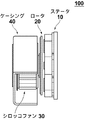
- FIG. 1 is a partially broken side view of a heating apparatus according to an embodiment of the present invention.
- the heating device 100 includes a stator (stator) 10, a rotor (rotor) 20, a sirocco fan (blower) 30, and a casing 40 that are disposed on the front side of the stator 10 with a gap therebetween.
- the stator 10 and the casing 40 are used, for example, fixed at predetermined positions in an electric vehicle, for example.
- the stator 10 and the rotor 20 are induction motors that constitute the drive unit of the heating device 100.
- the sirocco fan 30 constitutes a driven part of the induction motor, and is rotatably supported by the casing 40 together with the rotor 20.
- the rotor 20 faces the stator 10 with a predetermined gap, for example, with a gap of about 2 to 10 mm.
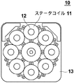
- FIG. 2 is a front view showing the configuration of the stator 10.
- the stator 10 is composed of a coil array including eight stator coils 11 arranged at equal intervals in the circumferential direction.
- the coil array is composed of two coil groups including four stator coils 11 each of which is connected in series. Stator coils 11 belonging to one coil group and stator coils 11 belonging to the other coil group are alternately arranged.
- the first AC power source sin power source
- a second AC power source cos power source whose frequency and voltage are controlled is applied to the power source.
- Each stator coil 11 is wound on a bobbin covering a magnetic core 12, and each magnetic core 12 is supported on a support plate 13 constituting a magnetic circuit.
- the support plate 13 is made of, for example, permalloy, and the stator coil 11 is made of, for example, a copper wire.
- the magnetic core 12 is made of ferrite, for example.
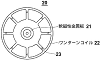
- FIG. 3 is a rear view of the rotor 20.
- the rotor 20 includes a disk-shaped soft magnetic metal plate 21 having a thickness of about 3 to 5 mm and eight one-turn coils 22 fixed on the surface of the soft magnetic metal plate 21 and arranged at equal intervals in the circumferential direction. Including.
- the one-turn coil 22 is arranged corresponding to the stator coil 11, receives a rotating magnetic field generated in the coil array, generates a circulating current, generates Joule heat by the circulating current, and rotates via the circulating current. It is rotationally driven by a magnetic field.
- the soft magnetic metal plate 21 receives the rotating magnetic field of the stator coil 11 and generates an eddy current inside.
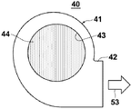
- FIG. 5 is a front view of the casing 40.
- the casing 40 includes a main body portion 41 that sucks the air flow 52 (FIG. 4) from the intake hole 43 and an air flow discharge portion 42 that extends from the main body portion 41 and discharges the air flow 53.
- a louver made up of a large number of vanes 44 is formed in the intake hole 43.
- the casing 40 is made of a resin having high heat insulation properties, and the thermal efficiency of the entire heating device is enhanced by selecting this material.
- the casing 40 has a protection function that surrounds and protects the sirocco fan 30 as a whole, and a rectification function that rectifies the air flow.
- the casing only needs to have a rectifying function, and does not necessarily require a sirocco fan to surround the entire sirocco fan or a protective function for protecting it.
- a two-phase alternating current whose frequency and voltage (power) are controlled is applied to each coil group of the coil array to generate a rotating magnetic field. Due to this rotating magnetic field, a circulating current is generated in the one-turn coil 22 of the rotor 20, and an eddy current is generated in the soft magnetic metal plate 21.
- the rotor 20 is given a rotational driving force from the stator 10 by the generated circulating current and eddy current and the rotating magnetic field. Further, Joule heat is generated in the one-turn coil 22 and the soft magnetic metal plate 21 by these circulating current and eddy current.
- an AC energy converter induction motor
- a stator and a rotor similar to the stator 10 and the rotor 20 is described in Japanese Patent Laid-Open No. 10-98860. This document is incorporated into the present invention by reference.
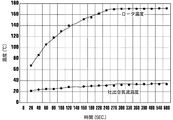
- FIG. 6 shows the characteristics measured by the heating device that was prototyped as an example of the present invention.
- the heating capacity was measured by how much the intake air temperature of 20 ° C. could be warmed at a predetermined frequency and a predetermined rotation speed. The temperature reached by the rotor at that time was also measured.
- the power source of the heating device was obtained by an inverter device using a battery as a power source.
- the gap between the stator 10 and the rotor 20 was 2.6 mm.
- gap can be selected in the range of about 2 mm to about 10 mm, for example.
- the impeller of the sirocco fan 30 had an outer diameter of 120 mm and an axial length of 53 mm.
- the blades and the frame were made of aluminum having a thickness of 1 mm.
- a 1.5 kHz two-phase alternating current having a phase difference of 90 degrees was applied to the coil array of the stator 10 of the prototype heating device.
- the applied voltage was adjusted and the power consumption was controlled so that the rotation speed of the sirocco fan 30 was 1500 rpm, the characteristics shown in FIG. 6 were obtained.
- the rotor temperature and the discharge air flow temperature were almost saturated, and the power consumption at that time was 446 W.
- the calorific value at this time was calculated to be about 400 W. Therefore, the power consumption by the blast power was about 46W.
- the saturated discharge air flow temperature was 33.7 ° C., and it was confirmed that sufficient heating capacity was obtained. Further, the saturation temperature of the rotor 20 at that time was 171 ° C.
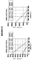
- FIG. 7 shows the measurement results of the motor characteristics of the heating device of the above example.
- 2 mm and 10 mm were adopted as the gap (GAP) between the stator 10 and the rotor 20.
- GAP gap between the stator 10 and the rotor 20.
- two-phase alternating current having a frequency of 400 Hz and a power supply voltage of 30 V and 50 V was applied, and electric characteristics and generated torque from the start-up were measured.
- the motor was started up several times, and the characteristics were measured each time. From the characteristics of FIG. 7, it can be understood that the selection / control of the torque that gives the air volume required for the sirocco fan is possible by selecting the gap length, the applied voltage, and the power supply frequency. Note that the control of the calorific value itself is preferably performed by controlling the applied voltage and / or the power supply frequency.
- frequency and / or voltage (power) control can be used for each adjustment of the heating temperature and the heating air speed.
- control in the range of 0.2 kHz to 5 kHz as the frequency is effective, and control in the range of 50 W to 500 W is effective as the power control.
- the upper limit of the reached temperature of the rotor 20 is about 500 ° C. in consideration of the used materials and environmental conditions.
- the heating device used in the above embodiment if about 5 to 10 heating devices are installed, the heating capacity required for the vehicle heating device can be obtained. In this case, for example, by arranging a heating device for each airflow outlet, it is not necessary to install an air duct and the like, and an improvement in equipment arrangement efficiency in the vehicle can be expected. In this case, it is possible to further set the temperature for each part in the vehicle.
- the preferable heating temperature of the upper body can be set individually from 24 ° C. to 28 ° C.
- the preferable heating temperature of the lower body can be set from 28 ° C. to 32 ° C.
- a gap may be provided between the stator 10 and the rotor 20, or an insulating material may be interposed therebetween.
- the stator 10 can be embedded and installed at a position that cannot be seen from the inside of the vehicle body, and the rotor 20 can be arranged on the indoor side so as to face the stator 10.
- a large number of stators may be arranged in advance, and the rotor may be arranged to face only the stator at an appropriate position among the stators. In this way, the number and arrangement of the heating devices can be determined at the final stage of vehicle manufacture.
- capacitance of the motor of the heating apparatus of the said Example is designed largely according to it, for example.
- a heating capability comparable to that of a conventional heating device using engine exhaust heat can be obtained.
- the reached temperature of the rotor is preferably set to about 200 ° C. to 500 ° C.
- the rotor can be downsized and the heat capacity of the rotor can be reduced. In this case, the rise time of the heating device can be shortened, and efficient vehicle heating becomes possible.
- the types of motors described in Patent Literature 4 and Patent Literature 5 can be suitably used.
- the electric motor used in the heating device of the present invention is not limited to the induction motor described in these patent documents as long as the rotor constituting the heat source rotates integrally with the blower.
- adopted the sirocco fan as an air blower was shown.
- the blower used in the heating device of the present invention is not necessarily limited to a sirocco fan, and can be fixed to a rotor serving as a heat source that generates Joule heat by eddy current and / or circulating current, and can rotate integrally therewith. If so, various types of blowers can be used.
- produces a rotating magnetic field by a two-phase alternating current was shown, you may generate
- the rotor that constitutes the heat source and the blower that generates the air flow including the heat from the heat source are integrally arranged, so that the device configuration is simplified.
- the heating device of the present invention wiring and piping connection are not required for the rotating portion in which the rotor constituting the heat source and the blower that generates the air flow are integrally formed. For this reason, it is easy to attach and detach the rotating part, which is the main part for maintenance of the heating device in an electric vehicle or the like, and the maintenance of the apparatus is simplified.
- the electric heating apparatus of this invention is not limited only to the structure of the said embodiment or an Example, The said embodiment and Heating apparatuses in which various modifications and changes are made from the configuration of the embodiment are also included in the scope of the present invention.
Landscapes
- Engineering & Computer Science (AREA)
- Physics & Mathematics (AREA)
- Mechanical Engineering (AREA)
- Thermal Sciences (AREA)
- General Engineering & Computer Science (AREA)
- Electromagnetism (AREA)
- Chemical & Material Sciences (AREA)
- Combustion & Propulsion (AREA)
- Air-Conditioning For Vehicles (AREA)
- Structures Of Non-Positive Displacement Pumps (AREA)
Abstract
Description
第1は、発熱体(熱源)と送風機とが別体であるため、装置構成が複雑なことである。第2は、熱源の温度上限が350℃程度と比較的低温であるため、熱源が大型になりやすいことである。第3は、熱源には一般に配線および配管の双方が付属するため、車両に対する熱源の脱着が容易ではなく、装置のメンテナンスが困難なことである。
Claims (10)
- 回転磁界を発生するように円周方向に沿って配列された複数のステータコイルを含むディスク状の固定子と、前記複数のステータコイルにそれぞれ対応して配置される複数のワンターンコイル、および、該ワンターンコイルを支持し該ワンターンコイルの前記固定子と反対側に配置された軟磁性金属板を含み、前記回転磁界により回転駆動されるディスク状の回転子とを有する電動機と、
前記軟磁性金属板上に前記ワンターンコイルと反対側に固定され、前記回転子と一体的に回転する複数の羽根を含む羽根車を有する送風機と、
を備えることを特徴とする電気式暖房装置。 - 前記送風機がシロッコファンであることを特徴とする請求項1に記載の電気式暖房装置。
- 前記回転磁界が、2相交流によって発生されることを特徴とする請求項1または2に記載の電気式暖房装置。
- 前記複数のステータコイルが、所定の周波数及び電圧の交流電圧が印加される第1群のステータコイルと、前記第1群のステータコイルに印加される交流電圧とは位相が90°異なる交流電圧が印加される第2群のステータコイルとを含み、前記ディスク上の固定子の円周方向に沿って、前記第1群のステータコイルと第2群のステータコイルとが交互に配置されていることを特徴とする請求項3に記載の電気式暖房装置。
- 前記第1群および第2群のステータコイルに印加される交流電圧の周波数が0.2kHzから5kHzの範囲で調整可能であることを特徴とする請求項4に記載の電気式暖房装置。
- 前記第1群および第2群のステータコイルに供給される交流電力が50Wから500Wの範囲で調整可能であることを特徴とする請求項4または5に記載の電気式暖房装置。
- 前記固定子と前記回転子とが、2mmから10mmの隙間を隔てて対向していることを特徴とする請求項1から6いずれかに記載の電気式暖房装置。
- 請求項1または2に記載の電気式暖房装置を備えたことを特徴とする電気自動車。
- 前記電気式暖房装置を、車両内の複数の空気流吹出し口毎に備えたことを特徴とする請求項8に記載の電気自動車。
- 前記電気式暖房装置における暖房能力が複数の空気流吹出し口毎に調整可能であることを特徴とする請求項9に記載の電気自動車。
Priority Applications (4)
| Application Number | Priority Date | Filing Date | Title |
|---|---|---|---|
| CN201280025880.7A CN103582579A (zh) | 2011-05-27 | 2012-05-25 | 电加热装置和电动车辆 |
| US14/122,624 US20140079375A1 (en) | 2011-05-27 | 2012-05-25 | Electric heating device and electric vehicle |
| KR1020137032723A KR20140033105A (ko) | 2011-05-27 | 2012-05-25 | 전기식 난방 장치 및 전기 자동차 |
| EP12793384.4A EP2716479A4 (en) | 2011-05-27 | 2012-05-25 | ELECTRIC HEATING DEVICE AND ELECTRIC VEHICLE THEREWITH |
Applications Claiming Priority (2)
| Application Number | Priority Date | Filing Date | Title |
|---|---|---|---|
| JP2011118904A JP2012245871A (ja) | 2011-05-27 | 2011-05-27 | 電気式暖房装置および電気自動車 |
| JP2011-118904 | 2011-05-27 |
Publications (1)
| Publication Number | Publication Date |
|---|---|
| WO2012164894A1 true WO2012164894A1 (ja) | 2012-12-06 |
Family
ID=47258770
Family Applications (1)
| Application Number | Title | Priority Date | Filing Date |
|---|---|---|---|
| PCT/JP2012/003432 Ceased WO2012164894A1 (ja) | 2011-05-27 | 2012-05-25 | 電気式暖房装置および電気自動車 |
Country Status (6)
| Country | Link |
|---|---|
| US (1) | US20140079375A1 (ja) |
| EP (1) | EP2716479A4 (ja) |
| JP (1) | JP2012245871A (ja) |
| KR (1) | KR20140033105A (ja) |
| CN (1) | CN103582579A (ja) |
| WO (1) | WO2012164894A1 (ja) |
Cited By (1)
| Publication number | Priority date | Publication date | Assignee | Title |
|---|---|---|---|---|
| WO2014083833A1 (ja) * | 2012-11-29 | 2014-06-05 | 株式会社Tbk | 暖房送風機及び車両 |
Families Citing this family (4)
| Publication number | Priority date | Publication date | Assignee | Title |
|---|---|---|---|---|
| JP6349102B2 (ja) * | 2014-02-21 | 2018-06-27 | 株式会社Soken | 空調装置用送風ユニット |
| JP2015212597A (ja) * | 2014-05-06 | 2015-11-26 | 株式会社日本自動車部品総合研究所 | 空調装置用送風ユニット |
| CN105818640A (zh) * | 2016-04-01 | 2016-08-03 | 浙江双荣汽车空调制造有限公司 | 一种电动汽车变频空调系统 |
| CN115930286B (zh) * | 2022-12-26 | 2026-03-27 | 华中科技大学 | 一种加热散热集成式电热扇装置 |
Citations (9)
| Publication number | Priority date | Publication date | Assignee | Title |
|---|---|---|---|---|
| JPH04194554A (ja) * | 1990-11-28 | 1992-07-14 | Michiko Takahashi | 誘導加熱型暖房方式 |
| JPH09118126A (ja) | 1995-10-27 | 1997-05-06 | Nissan Motor Co Ltd | 車両用ヒートポンプ式冷暖房装置 |
| JPH1098860A (ja) | 1996-09-20 | 1998-04-14 | Namiki Precision Jewel Co Ltd | 交流エネルギー変換器 |
| JPH10108426A (ja) * | 1996-10-01 | 1998-04-24 | Namiki Precision Jewel Co Ltd | 交流エネルギー変換駆動機器 |
| JPH11105537A (ja) | 1997-09-30 | 1999-04-20 | Isuzu Motors Ltd | 電気自動車用ヒートポンプ式空調装置 |
| JPH11332186A (ja) * | 1998-05-12 | 1999-11-30 | Namiki Precision Jewel Co Ltd | 交流エネルギー変換機 |
| JP2000033916A (ja) | 1998-07-21 | 2000-02-02 | Omori Mach Co Ltd | 包装装置 |
| JP4337961B2 (ja) | 1999-06-24 | 2009-09-30 | 哲夫 関谷 | 電気エネルギ変換器 |
| JP2010154737A (ja) | 2008-11-26 | 2010-07-08 | Tetsuo Sekiya | エネルギー変換器 |
Family Cites Families (7)
| Publication number | Priority date | Publication date | Assignee | Title |
|---|---|---|---|---|
| DE20221482U1 (de) * | 1970-04-18 | 2006-02-16 | Webasto Ag | Zusatzheizgerät für Personenfahrzeuge |
| JPS608110A (ja) * | 1983-06-27 | 1985-01-17 | Nippon Denso Co Ltd | 自動車用空調装置 |
| FR2677508B1 (fr) * | 1991-06-06 | 1994-12-30 | Labavia | Perfectionnements aux machines tournantes electriques du genre des ralentisseurs, notamment pour le chauffage d'un habitacle de vehicule. |
| US6935944B2 (en) * | 2003-11-15 | 2005-08-30 | Floyd E. Bigelow, Jr. | Air systems for vehicles |
| KR100663641B1 (ko) * | 2006-04-06 | 2007-01-05 | 주식회사 아모텍 | 일체형 스테이터의 제조방법, 이를 이용한 레이디얼코어타입 더블 로터 방식의 비엘디씨 모터 및 그의제조방법 |
| EP2053721A2 (en) * | 2007-10-23 | 2009-04-29 | Hitachi Ltd. | Rotating machine |
| EP2402209B1 (de) * | 2008-01-24 | 2013-06-05 | Eberspächer catem GmbH & Co. KG | Elektrische Zusatzheizung für ein Kraftfahrzeug |
-
2011
- 2011-05-27 JP JP2011118904A patent/JP2012245871A/ja active Pending
-
2012
- 2012-05-25 EP EP12793384.4A patent/EP2716479A4/en not_active Withdrawn
- 2012-05-25 KR KR1020137032723A patent/KR20140033105A/ko not_active Withdrawn
- 2012-05-25 WO PCT/JP2012/003432 patent/WO2012164894A1/ja not_active Ceased
- 2012-05-25 CN CN201280025880.7A patent/CN103582579A/zh active Pending
- 2012-05-25 US US14/122,624 patent/US20140079375A1/en not_active Abandoned
Patent Citations (9)
| Publication number | Priority date | Publication date | Assignee | Title |
|---|---|---|---|---|
| JPH04194554A (ja) * | 1990-11-28 | 1992-07-14 | Michiko Takahashi | 誘導加熱型暖房方式 |
| JPH09118126A (ja) | 1995-10-27 | 1997-05-06 | Nissan Motor Co Ltd | 車両用ヒートポンプ式冷暖房装置 |
| JPH1098860A (ja) | 1996-09-20 | 1998-04-14 | Namiki Precision Jewel Co Ltd | 交流エネルギー変換器 |
| JPH10108426A (ja) * | 1996-10-01 | 1998-04-24 | Namiki Precision Jewel Co Ltd | 交流エネルギー変換駆動機器 |
| JPH11105537A (ja) | 1997-09-30 | 1999-04-20 | Isuzu Motors Ltd | 電気自動車用ヒートポンプ式空調装置 |
| JPH11332186A (ja) * | 1998-05-12 | 1999-11-30 | Namiki Precision Jewel Co Ltd | 交流エネルギー変換機 |
| JP2000033916A (ja) | 1998-07-21 | 2000-02-02 | Omori Mach Co Ltd | 包装装置 |
| JP4337961B2 (ja) | 1999-06-24 | 2009-09-30 | 哲夫 関谷 | 電気エネルギ変換器 |
| JP2010154737A (ja) | 2008-11-26 | 2010-07-08 | Tetsuo Sekiya | エネルギー変換器 |
Non-Patent Citations (1)
| Title |
|---|
| See also references of EP2716479A4 * |
Cited By (1)
| Publication number | Priority date | Publication date | Assignee | Title |
|---|---|---|---|---|
| WO2014083833A1 (ja) * | 2012-11-29 | 2014-06-05 | 株式会社Tbk | 暖房送風機及び車両 |
Also Published As
| Publication number | Publication date |
|---|---|
| KR20140033105A (ko) | 2014-03-17 |
| JP2012245871A (ja) | 2012-12-13 |
| EP2716479A1 (en) | 2014-04-09 |
| EP2716479A4 (en) | 2014-12-31 |
| CN103582579A (zh) | 2014-02-12 |
| US20140079375A1 (en) | 2014-03-20 |
Similar Documents
| Publication | Publication Date | Title |
|---|---|---|
| US10637319B2 (en) | Coreless rotating electrical machine with stator including cylindrical coil and cooling method therefor | |
| US6788022B2 (en) | Electric motor | |
| CN101263642B (zh) | 带有永磁体的电机 | |
| US6393208B1 (en) | Compressor with integrated impeller and motor | |
| CN106573522B (zh) | 用于机动车的暖风机装置 | |
| WO2012164894A1 (ja) | 電気式暖房装置および電気自動車 | |
| US7859146B2 (en) | End winding cooling | |
| CN107667458B (zh) | 电子开关电马达及相应的空气脉动装置 | |
| KR102400801B1 (ko) | 전동 과급기 | |
| CN110380575B (zh) | 一种带有径流式散热风轮的自励同步发电机 | |
| JP3901146B2 (ja) | 交流電源直結型ブラシレスdcモータおよびそれを搭載した電気機器 | |
| JP6349102B2 (ja) | 空調装置用送風ユニット | |
| JP5611348B2 (ja) | Hvac−送風機用の空芯コイル巻線 | |
| JP6711928B2 (ja) | エアコントローラ | |
| WO2016090735A1 (zh) | 一种自动调速的ecm电机及其应用的冰柜 | |
| JP6185710B2 (ja) | 暖房送風機及び車両 | |
| JP5312521B2 (ja) | 電動機および空調機 | |
| US20170110942A1 (en) | Induction motor and method of manufacture | |
| CN202260941U (zh) | 永磁飞轮式发电机 | |
| CN102340209B (zh) | 永磁飞轮式发电机 | |
| CN120593396A (zh) | 空气调节设备和暖风机 | |
| JP4415979B2 (ja) | 交流電源直結型ブラシレスdcモータおよびそれを搭載した電気機器 | |
| WO2013000181A1 (en) | Device with inductor and rotor assembly | |
| JPS5886850A (ja) | 交流発電機 | |
| JPS5846860A (ja) | 交流発電機 |
Legal Events
| Date | Code | Title | Description |
|---|---|---|---|
| 121 | Ep: the epo has been informed by wipo that ep was designated in this application |
Ref document number: 12793384 Country of ref document: EP Kind code of ref document: A1 |
|
| WWE | Wipo information: entry into national phase |
Ref document number: 14122624 Country of ref document: US |
|
| NENP | Non-entry into the national phase |
Ref country code: DE |
|
| ENP | Entry into the national phase |
Ref document number: 20137032723 Country of ref document: KR Kind code of ref document: A |
|
| WWE | Wipo information: entry into national phase |
Ref document number: 2012793384 Country of ref document: EP |