WO2012165556A1 - Procédé de photographie d'image, procédé de lecture de photographie d'image, modulateur spatial d'éclairage, dispositif de lecture d'image et dispositif de formation d'hologramme numérique - Google Patents
Procédé de photographie d'image, procédé de lecture de photographie d'image, modulateur spatial d'éclairage, dispositif de lecture d'image et dispositif de formation d'hologramme numérique Download PDFInfo
- Publication number
- WO2012165556A1 WO2012165556A1 PCT/JP2012/064095 JP2012064095W WO2012165556A1 WO 2012165556 A1 WO2012165556 A1 WO 2012165556A1 JP 2012064095 W JP2012064095 W JP 2012064095W WO 2012165556 A1 WO2012165556 A1 WO 2012165556A1
- Authority
- WO
- WIPO (PCT)
- Prior art keywords
- light modulator
- spatial light
- hologram
- light
- image forming
- Prior art date
- Legal status (The legal status is an assumption and is not a legal conclusion. Google has not performed a legal analysis and makes no representation as to the accuracy of the status listed.)
- Ceased
Links
Images






Classifications
-
- G—PHYSICS
- G03—PHOTOGRAPHY; CINEMATOGRAPHY; ANALOGOUS TECHNIQUES USING WAVES OTHER THAN OPTICAL WAVES; ELECTROGRAPHY; HOLOGRAPHY
- G03H—HOLOGRAPHIC PROCESSES OR APPARATUS
- G03H1/00—Holographic processes or apparatus using light, infrared or ultraviolet waves for obtaining holograms or for obtaining an image from them; Details peculiar thereto
- G03H1/26—Processes or apparatus specially adapted to produce multiple sub- holograms or to obtain images from them, e.g. multicolour technique
- G03H1/268—Holographic stereogram
-
- G—PHYSICS
- G02—OPTICS
- G02B—OPTICAL ELEMENTS, SYSTEMS OR APPARATUS
- G02B30/00—Optical systems or apparatus for producing three-dimensional [3D] effects, e.g. stereoscopic images
- G02B30/20—Optical systems or apparatus for producing three-dimensional [3D] effects, e.g. stereoscopic images by providing first and second parallax images to an observer's left and right eyes
- G02B30/22—Optical systems or apparatus for producing three-dimensional [3D] effects, e.g. stereoscopic images by providing first and second parallax images to an observer's left and right eyes of the stereoscopic type
- G02B30/25—Optical systems or apparatus for producing three-dimensional [3D] effects, e.g. stereoscopic images by providing first and second parallax images to an observer's left and right eyes of the stereoscopic type using polarisation techniques
-
- G—PHYSICS
- G02—OPTICS
- G02F—OPTICAL DEVICES OR ARRANGEMENTS FOR THE CONTROL OF LIGHT BY MODIFICATION OF THE OPTICAL PROPERTIES OF THE MEDIA OF THE ELEMENTS INVOLVED THEREIN; NON-LINEAR OPTICS; FREQUENCY-CHANGING OF LIGHT; OPTICAL LOGIC ELEMENTS; OPTICAL ANALOGUE/DIGITAL CONVERTERS
- G02F1/00—Devices or arrangements for the control of the intensity, colour, phase, polarisation or direction of light arriving from an independent light source, e.g. switching, gating or modulating; Non-linear optics
- G02F1/01—Devices or arrangements for the control of the intensity, colour, phase, polarisation or direction of light arriving from an independent light source, e.g. switching, gating or modulating; Non-linear optics for the control of the intensity, phase, polarisation or colour
- G02F1/09—Devices or arrangements for the control of the intensity, colour, phase, polarisation or direction of light arriving from an independent light source, e.g. switching, gating or modulating; Non-linear optics for the control of the intensity, phase, polarisation or colour based on magneto-optical elements, e.g. exhibiting Faraday effect
-
- G—PHYSICS
- G03—PHOTOGRAPHY; CINEMATOGRAPHY; ANALOGOUS TECHNIQUES USING WAVES OTHER THAN OPTICAL WAVES; ELECTROGRAPHY; HOLOGRAPHY
- G03H—HOLOGRAPHIC PROCESSES OR APPARATUS
- G03H1/00—Holographic processes or apparatus using light, infrared or ultraviolet waves for obtaining holograms or for obtaining an image from them; Details peculiar thereto
- G03H1/02—Details of features involved during the holographic process; Replication of holograms without interference recording
-
- G—PHYSICS
- G03—PHOTOGRAPHY; CINEMATOGRAPHY; ANALOGOUS TECHNIQUES USING WAVES OTHER THAN OPTICAL WAVES; ELECTROGRAPHY; HOLOGRAPHY
- G03H—HOLOGRAPHIC PROCESSES OR APPARATUS
- G03H1/00—Holographic processes or apparatus using light, infrared or ultraviolet waves for obtaining holograms or for obtaining an image from them; Details peculiar thereto
- G03H1/02—Details of features involved during the holographic process; Replication of holograms without interference recording
- G03H1/024—Hologram nature or properties
- G03H1/0248—Volume holograms
-
- G—PHYSICS
- G03—PHOTOGRAPHY; CINEMATOGRAPHY; ANALOGOUS TECHNIQUES USING WAVES OTHER THAN OPTICAL WAVES; ELECTROGRAPHY; HOLOGRAPHY
- G03H—HOLOGRAPHIC PROCESSES OR APPARATUS
- G03H1/00—Holographic processes or apparatus using light, infrared or ultraviolet waves for obtaining holograms or for obtaining an image from them; Details peculiar thereto
- G03H1/04—Processes or apparatus for producing holograms
- G03H1/0443—Digital holography, i.e. recording holograms with digital recording means
-
- G—PHYSICS
- G03—PHOTOGRAPHY; CINEMATOGRAPHY; ANALOGOUS TECHNIQUES USING WAVES OTHER THAN OPTICAL WAVES; ELECTROGRAPHY; HOLOGRAPHY
- G03H—HOLOGRAPHIC PROCESSES OR APPARATUS
- G03H1/00—Holographic processes or apparatus using light, infrared or ultraviolet waves for obtaining holograms or for obtaining an image from them; Details peculiar thereto
- G03H1/04—Processes or apparatus for producing holograms
- G03H1/08—Synthesising holograms, i.e. holograms synthesized from objects or objects from holograms
- G03H1/0866—Digital holographic imaging, i.e. synthesizing holobjects from holograms
-
- G—PHYSICS
- G03—PHOTOGRAPHY; CINEMATOGRAPHY; ANALOGOUS TECHNIQUES USING WAVES OTHER THAN OPTICAL WAVES; ELECTROGRAPHY; HOLOGRAPHY
- G03H—HOLOGRAPHIC PROCESSES OR APPARATUS
- G03H1/00—Holographic processes or apparatus using light, infrared or ultraviolet waves for obtaining holograms or for obtaining an image from them; Details peculiar thereto
- G03H1/04—Processes or apparatus for producing holograms
- G03H1/08—Synthesising holograms, i.e. holograms synthesized from objects or objects from holograms
- G03H1/0891—Processes or apparatus adapted to convert digital holographic data into a hologram
-
- G—PHYSICS
- G02—OPTICS
- G02F—OPTICAL DEVICES OR ARRANGEMENTS FOR THE CONTROL OF LIGHT BY MODIFICATION OF THE OPTICAL PROPERTIES OF THE MEDIA OF THE ELEMENTS INVOLVED THEREIN; NON-LINEAR OPTICS; FREQUENCY-CHANGING OF LIGHT; OPTICAL LOGIC ELEMENTS; OPTICAL ANALOGUE/DIGITAL CONVERTERS
- G02F2203/00—Function characteristic
- G02F2203/12—Function characteristic spatial light modulator
-
- G—PHYSICS
- G03—PHOTOGRAPHY; CINEMATOGRAPHY; ANALOGOUS TECHNIQUES USING WAVES OTHER THAN OPTICAL WAVES; ELECTROGRAPHY; HOLOGRAPHY
- G03H—HOLOGRAPHIC PROCESSES OR APPARATUS
- G03H1/00—Holographic processes or apparatus using light, infrared or ultraviolet waves for obtaining holograms or for obtaining an image from them; Details peculiar thereto
- G03H1/22—Processes or apparatus for obtaining an optical image from holograms
- G03H1/2294—Addressing the hologram to an active spatial light modulator
-
- G—PHYSICS
- G03—PHOTOGRAPHY; CINEMATOGRAPHY; ANALOGOUS TECHNIQUES USING WAVES OTHER THAN OPTICAL WAVES; ELECTROGRAPHY; HOLOGRAPHY
- G03H—HOLOGRAPHIC PROCESSES OR APPARATUS
- G03H1/00—Holographic processes or apparatus using light, infrared or ultraviolet waves for obtaining holograms or for obtaining an image from them; Details peculiar thereto
- G03H1/0005—Adaptation of holography to specific applications
- G03H2001/0088—Adaptation of holography to specific applications for video-holography, i.e. integrating hologram acquisition, transmission and display
-
- G—PHYSICS
- G03—PHOTOGRAPHY; CINEMATOGRAPHY; ANALOGOUS TECHNIQUES USING WAVES OTHER THAN OPTICAL WAVES; ELECTROGRAPHY; HOLOGRAPHY
- G03H—HOLOGRAPHIC PROCESSES OR APPARATUS
- G03H1/00—Holographic processes or apparatus using light, infrared or ultraviolet waves for obtaining holograms or for obtaining an image from them; Details peculiar thereto
- G03H1/02—Details of features involved during the holographic process; Replication of holograms without interference recording
- G03H2001/026—Recording materials or recording processes
- G03H2001/0268—Inorganic recording material, e.g. photorefractive crystal [PRC]
-
- G—PHYSICS
- G03—PHOTOGRAPHY; CINEMATOGRAPHY; ANALOGOUS TECHNIQUES USING WAVES OTHER THAN OPTICAL WAVES; ELECTROGRAPHY; HOLOGRAPHY
- G03H—HOLOGRAPHIC PROCESSES OR APPARATUS
- G03H1/00—Holographic processes or apparatus using light, infrared or ultraviolet waves for obtaining holograms or for obtaining an image from them; Details peculiar thereto
- G03H1/26—Processes or apparatus specially adapted to produce multiple sub- holograms or to obtain images from them, e.g. multicolour technique
- G03H1/268—Holographic stereogram
- G03H2001/269—Two and more than two steps recording process
-
- G—PHYSICS
- G03—PHOTOGRAPHY; CINEMATOGRAPHY; ANALOGOUS TECHNIQUES USING WAVES OTHER THAN OPTICAL WAVES; ELECTROGRAPHY; HOLOGRAPHY
- G03H—HOLOGRAPHIC PROCESSES OR APPARATUS
- G03H2222/00—Light sources or light beam properties
- G03H2222/31—Polarised light
-
- G—PHYSICS
- G03—PHOTOGRAPHY; CINEMATOGRAPHY; ANALOGOUS TECHNIQUES USING WAVES OTHER THAN OPTICAL WAVES; ELECTROGRAPHY; HOLOGRAPHY
- G03H—HOLOGRAPHIC PROCESSES OR APPARATUS
- G03H2225/00—Active addressable light modulator
- G03H2225/30—Modulation
-
- G—PHYSICS
- G03—PHOTOGRAPHY; CINEMATOGRAPHY; ANALOGOUS TECHNIQUES USING WAVES OTHER THAN OPTICAL WAVES; ELECTROGRAPHY; HOLOGRAPHY
- G03H—HOLOGRAPHIC PROCESSES OR APPARATUS
- G03H2240/00—Hologram nature or properties
- G03H2240/20—Details of physical variations exhibited in the hologram
- G03H2240/25—Magnetic variations
-
- G—PHYSICS
- G03—PHOTOGRAPHY; CINEMATOGRAPHY; ANALOGOUS TECHNIQUES USING WAVES OTHER THAN OPTICAL WAVES; ELECTROGRAPHY; HOLOGRAPHY
- G03H—HOLOGRAPHIC PROCESSES OR APPARATUS
- G03H2260/00—Recording materials or recording processes
- G03H2260/30—Details of photosensitive recording material not otherwise provided for
- G03H2260/35—Rewritable material allowing several record and erase cycles
Definitions
- the present invention relates to a holography apparatus suitable for reproducing a moving image of a stereoscopic image.
- Patent Documents 1 and 2 propose a technique for reproducing a moving image of a stereoscopic image using holography (hereinafter referred to as “electronic holography”).
- the technique of electronic holography proposed in these is of a horizontal parallax type using an existing spatial light modulator, and reproduction of a stereoscopic moving image by electronic holography cannot be realized in a full parallax state. See also Non-Patent Document 1 on magneto-optical holograms.
- a spatial light modulator (hereinafter also referred to as “SLM”) needs to have the following innovative performance.
- SLM spatial light modulator
- the SLM for electronic holography requires a very large number of pixels (several hundred thousand times to realize the same screen size as the existing SLM). Not only is the formation technology easy, but pixel wiring is not complicated.
- An object of the present invention is to provide a spatial modulator that implements at least one of the functions (1) to (3).
- the magneto-optical material is a material that can control the polarization state of light by the magnetization state. Since the magnetization state of the magneto-optical material can be controlled in a very small unit, so-called nanopixels in the order of the light wavelength can be formed if the pixels can be configured with an arbitrary width. In addition, the magneto-optical material can be easily reversed in its magnetic moment, for example, by heating it, so that the polarization state of light can be controlled. Therefore, its formation is easy and no wiring is required.
- the heated magneto-optic material instantaneously reverses its magnetic moment, it can be driven at an ultra-high speed.
- FIG. 1A shows the principle of the polarization state by a magneto-optical material.
- P-polarized light When P-polarized light is incident, it rotates according to the direction of the magnetic moment.
- the rotated light In the example of 1A in which the magnetic moment is directed toward the front side of the paper, the rotated light generates S-polarized light that is directed to the left side in the figure, and in the example 1B of the magnetic moment that is directed to the back side of the paper, the S-polarized light is generated. Is done.
- FIG. 1B when regions having different magnetic moments are arranged in the magneto-optical material 1C, interference between S-polarized light in the emitted light is obtained, and a hologram can be formed. .
- a predetermined intensity is required for S-polarized light in order to form a visible hologram.
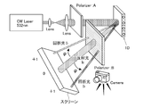
- the present inventors assembled an experimental apparatus shown in FIG. 2 in order to examine the intensity of S-polarized light.
- the magneto-optical material 1D made of TbFe
- the magnetic moment is reversed for each 1 ⁇ m lattice.
- reflected light transmitted light in FIG. 1B
- diffracted light S-polarized light in FIG. 1B
- the diffraction angle ⁇ was 15 degrees.
- FIG. 4 shows the relationship between the polarization angle and the diffracted light I 1 / reflected light I 0 in the magneto-optical material 1D.
- FIG. 5A shows a Fourier transform pattern written on the magneto-optical material 1D.
- the Fourier transform pattern is formed as follows. That is, first, a two-dimensional image of the character “A” is Fourier transformed by a computer to obtain a Fourier image (hologram pattern). After the Fourier image is digitized (binarized), thermomagnetic writing is performed on the magneto-optical material (TbFe) as a magnetic hologram bit by bit.
- FIG. 5B shows an image reproduced on the screen of FIG. As shown in FIG. 5B, it can be seen that the letter “A” is imaged by the diffracted light and has a luminous intensity sufficient for visual recognition.
- the hologram formed by the interference between the reference light and the target light is directly written on the magneto-optical material. Yes.
- the hologram formed thereby is an analog pattern.
- a digital hologram pattern binarized corresponding to the pixels of the magneto-optical material is obtained from the hologram pattern formed by the reference light and the target light. This digital hologram pattern is written on the magneto-optical material.
- the viewing angle of a stereoscopic image is ⁇
- the wavelength of incident light is ⁇
- the pixel pitch is ⁇
- the following relational expression is established.
- ⁇ 2sin-1 ( ⁇ / 2 ⁇ )
- the viewing angle ⁇ is about 30 degrees or more. If such a wide viewing angle can be ensured, the stereoscopic image reproduced on the stereoscopic image forming surface becomes full parallax and is suitable for practical use.
- the above formula is based on the condition that incident light is incident perpendicularly to the digital hologram pattern.
- incident light is incident obliquely with respect to the digital hologram pattern, that is, since reference light is also incident obliquely, the apparent pitch of pixels at that time is reduced.
- the interference fringes constituting the hologram become fine.
- the hologram is fixed in an analog manner (that is, in a plane), but in the digital hologram, for example, the density of the interference fringe is averaged for each pixel and the value for each pixel is determined. If the pattern becomes too fine, the stripe pattern may not be reflected.
- incident light that is, reference light
- the vertical in this specification is not a vertical in a strict sense, and an error on the apparatus is allowed.
- the hologram generation surface light reception of the hologram camera
- a slight inclination of the reference beam with respect to the surface is allowed.
- the vertical in this specification includes such a slight inclination (for example, 5 degrees or less, more preferably 3 degrees or less).
- the first aspect of the present invention is defined as follows.
- a writing step is defined as follows.
- the hologram formed by the interference between the reference light and the target light is generated in the first region and the second region in the magneto-optical material of the spatial light modulator. Since digitization is performed corresponding to the defined pixels, the digital hologram pattern can be easily stored, transferred, processed, and other processes. Since each value of the digital hologram pattern corresponds to a pixel of the spatial light modulator, it is easy and fast to write and rewrite the digital hologram pattern on the magneto-optical material of the spatial light modulator. .
- the reference light is incident perpendicularly to the hologram forming surface.
- incident light can be vertically incident on the digital hologram pattern during image reproduction. Therefore, the maximum viewing angle is ensured with respect to the pixel size (pitch) of the digital hologram pattern.
- the reference light and the incident light have the same wavelength, but different wavelengths can be used as long as the image can be reproduced. If the linearly polarized incident light is incident on the digital hologram pattern of the magneto-optical material and the output light (zero order light) is rotated by 90 degrees, sufficient light intensity can be obtained for the diffracted light. Therefore, a visible image by diffracted light can be obtained by cutting the emitted light with the polarizing plate.
- This invention is prescribed
- a three-dimensional image forming surface made of a magneto-optical material The magnetic moment axis is aligned in the vertical direction on the three-dimensional image forming surface; A first region in which the axis of the magnetic moment has a first direction and a second region opposite to the first direction are formed; The minimum unit width of the first region and the second region is 1 ⁇ m or less. Spatial light modulator.
- the spatial light modulator defined in this way, since the axis of the magnetic moment of the stereoscopic image forming surface is aligned in a certain direction, by partially controlling the direction of the magnetic moment on the stereoscopic image forming surface, Regions (first region and second region) having different magnetic moment directions can be formed on the three-dimensional image forming surface. Light incident on the first region and the second region having different magnetic moment directions diffracts in different directions. Therefore, a hologram (light interference fringe) is formed by the first region and the second region, and a three-dimensional image can be formed by causing the affected light to interfere.
- the direction of the magnetic moment can be controlled by heating.
- the magnetic moment of only the heated portion can be reversed by adjusting the heating time to a short time of about 10 ns, for example. According to the study by the present inventors, the heating time is reduced to 50 ps.
- a region having a width of 1 ⁇ m or less on the three-dimensional image forming surface can be heated in a short time.
- the first region and the second region having different magnetic moment directions can be formed with a width of 1 ⁇ m or less.
- a stereoscopic image with a large viewing angle can be formed. For example, if the viewing angle of a stereoscopic image is ⁇ , the wavelength of incident light is ⁇ , and the pixel pitch is ⁇ , the following relational expression is established.
- the viewing angle ⁇ 2sin-1 ( ⁇ / 2 ⁇ )
- the viewing angle ⁇ is about 30 degrees or more. If such a wide viewing angle can be ensured, the stereoscopic image reproduced on the stereoscopic image forming surface becomes full parallax and is suitable for practical use.
- FIG. 1 is a schematic diagram illustrating the relationship between the magneto-optical effect and the diffraction phenomenon.
- the structure of the observation apparatus for observing the optical diffraction effect by a magneto-optical material is shown.
- 2 shows an image reproduced on a screen when using a magneto-optical material in which magnetic moments are formed in a lattice shape (the directions of adjacent magnetic moments are different) in the observation apparatus of FIG.
- the relationship between the polarization angle of the incident light and the diffracted light I 1 / reflected light Io is shown.
- FIG. 5A is an enlarged plan view of a magneto-optical material on which a magnetic moment pattern (digital hologram) corresponding to the Fourier image of the two-dimensional image “A” is formed, and FIG. A reproduced image of a two-dimensional Fourier image is shown.
- 1 shows a structure of a spatial light modulator according to an embodiment of the present invention.
- 1 shows a configuration of a holography device according to an embodiment of the present invention.
- 2 shows a configuration of a holography device according to another embodiment of the present invention.
- 2 shows a configuration of a holography device according to another embodiment of the present invention.
- the imaging object in the Example of this invention is shown.
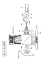
- the structure of the hologram acquisition apparatus of the Example of this invention is shown.
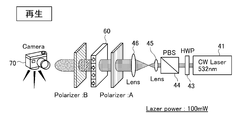
- FIG. 12 shows a hologram obtained with the apparatus of FIG. 1 shows a configuration of a hologram reproducing apparatus according to an embodiment of the present invention.
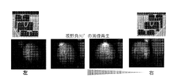
- FIG. 14 shows a photograph of a three-dimensional image reproduced by the hologram reproducing apparatus of FIG. 13 taken at a different angle.
- the magneto-optical material is not particularly limited as long as the phase of light can be controlled by the magnetization state, that is, the direction of the magnetization vector, but a metal magnetic material such as TbFe or DyFe or a transparent oxide magnetic material such as YIG is used. be able to.
- the three-dimensional image forming surface is formed of the magneto-optical material.
- One stereoscopic image forming surface is preferably formed of one type of magneto-optical material, but this does not exclude the formation of one stereoscopic image forming surface of a plurality of magneto-optical materials.
- the stereoscopic image forming surface is preferably a smooth surface in order to avoid light scattering and disordered phase change.
- the three-dimensional image forming surface is not limited to a flat surface, and may be a curved surface such as a spherical surface.
- the axial direction of the magnetic vector is aligned in a certain direction, preferably the vertical direction, on the entire surface of the stereoscopic image forming surface.
- a protective film is preferably formed on the surface of the stereoscopic image forming surface. This protective film is provided to prevent modification (oxidation or the like) of the magneto-optical material on the three-dimensional image forming surface.
- this protective film also has a function of overlapping and reflecting light between the stereoscopic image forming surface and amplifying the phase change.
- the coercive force is reduced and the magnetization is reversed by a surrounding magnetic field or an external magnetic field.
- Heating can be cited as a specific measure for that purpose.
- the amount of heat applied to the three-dimensional image forming surface by heating is not limited as long as it reduces the coercive force as described above, and it is not always necessary to raise the temperature of the magneto-optical material constituting the three-dimensional image forming surface to the Curie temperature.
- the heating time is preferably the minimum time required to reverse the magnetization moment of the heating target region, and heating for a long time may transfer heat to a region other than the heating target region and change the magnetization vector of the transmitted portion. This is not preferable.
- the magnetic moment can be reversed in an irradiation time of about 10 ns using a laser beam capable of heating the magneto-optical material constituting the stereoscopic image forming surface.
- a laser beam capable of heating the magneto-optical material constituting the stereoscopic image forming surface.
- a first region and a second region having different magnetization moment directions are formed on the stereoscopic image forming surface. These regions can be formed to have an arbitrary width and shape, irrespective of whether continuous or discontinuous. If a minimum unit area to be the first area or the second area is determined in advance, the area becomes a pixel, and a hologram can be formed. Here, if the width of the pixel is 1 ⁇ m or less, in other words, if the minimum unit width of the first region and the second region is 1 ⁇ m or less, a viewing angle of about 30 degrees can be obtained in the stereoscopic image. Thereby, a full parallax stereoscopic image is obtained.
- the lower limit of the pixel width is not particularly limited as long as the laser beam for heating can be condensed, but it is considered that the lower limit is 0.1 ⁇ m because of the thermal diffusion rate and the condensing optical system.
- the first region and the second region can have arbitrary shapes. In other words, the shape of the pixel is not limited to a square, and other polygonal diameters or circles may be used. In order to prevent the influence of heat applied to adjacent pixels, a small gap can be provided between the pixels.
- the entire first surface of the thin plate can be used as the stereoscopic image forming surface 3.
- the manufacturing method of this thin plate 1 may be a general magnetic thin film forming technique, such as a sputtering method or a sol-gel method.
- FIG. 6B shows a partially enlarged plan view of the stereoscopic image forming surface. As shown in FIG. 6B, circular pixels are formed on the three-dimensional image forming surface 3, and are defined as a first region 5 and a second region 6 depending on the directions of the respective magnetization vectors. Note that the first and second designations are reversed if the direction of the magnetization vector is different even for pixels on the same coordinates.
- the spatial light modulator is not limited to a thin plate shape, and it is sufficient that a part of the bulk of the magneto-optical material is a smooth surface and the axial direction of the magnetization vector is aligned with the smooth surface.
- the direction of the axis of the magnetization vector is preferably maintained from one surface (stereoscopic image forming surface 3) to the other surface (back surface 4) (FIG. 6 ( C)).
- the plate thickness is preferably 100 nm in order to obtain such characteristics.
- the laser light for controlling the direction of the magnetization vector can be irradiated to the thin plate spatial light modulator 1 from either the front or back direction.
- the thickness of the thin plate-like spatial light modulator is preferably 100 nm or less.
- a hologram (light interference fringes) can be formed on the three-dimensional image forming surface 3 of the spatial light modulator having the above configuration by the following method.
- Predetermined hologram When the three-dimensional image forming surface 3 is irradiated with energy that is focused to a pixel width or smaller and that can change the direction of the magnetic moment of the magneto-optical material, the energy beam of the portion irradiated with the energy beam is irradiated. The magnetic moment is reversed.
- a predetermined hologram is digitally processed and energy beam irradiation or non-irradiation is determined according to the value of each pixel. For example, a laser beam can be used as the energy beam.
- the energy beam may be irradiated from the back surface 4 side.
- a laser beam will be taken as an example of a representative example of the energy beam, and the description will proceed.
- the laser beam may be turned off in the pixel. However, it takes time to adjust the scanning device in order to scan a laser beam with a precision of 1 ⁇ m or less with a laser beam.
- the width of the pixel is 10 ⁇ m or more, and the direction of the magnetization vector cannot be controlled for each desired pixel on the stereoscopic image forming surface even if the laser beam reflected by the pixel is incident as it is.
- the pixel information of the optical element cannot be transferred to the element on the stereoscopic image forming surface. Therefore, a laser beam is irradiated to each pixel of the optical element, a lens is provided between the optical element and the stereoscopic image forming surface, and the diameter of the laser beam reflected by each pixel of the optical element is reduced to reduce the stereoscopic image forming surface. It is preferable to irradiate each pixel.
- the laser beam applied to each pixel of the optical element may be set to 1 ⁇ m or less in advance. In the above description, of course, the laser beam applied to the optical element may have a light beam width that covers the entire reflection surface of the optical element.
- a hologram (hereinafter sometimes referred to as “mother hologram”) is created.
- the subsequent processing may be the same as described above, but the mother hologram can be transferred to the hologram on the three-dimensional image forming surface by digitally processing the mother hologram and reflecting the result on each pixel of the optical element. Even if the subject is a moving image, considering the one frame and one frame, the above processing is repeated. Therefore, a hologram corresponding to the one frame and one frame is formed on the three-dimensional image forming surface, and the reference light is supplied there. It can be seen that the three-dimensional moving image corresponding to the target moving image can be reproduced.
- hologram reproduction will be described.
- the linearly polarized reference light is incident on the stereoscopic image forming surface 3 on which the hologram is formed, the emitted light is diffracted according to the direction of the magnetization vector on the stereoscopic image forming surface 3 to form a stereoscopic image.
- a polarizing plate is arranged on the stereoscopic image forming surface 3 on the side where the stereoscopic image is formed in order to remove the influence of the reference light. It is preferable.
- a ⁇ / 2 polarizing plate can be used as this polarizing plate.
- the linearly polarized reference light can be obtained by interposing a polarizing plate between the light source and the spatial light modulator, or by using a liquid crystal or the like as the light source itself as a polarized light source.
- FIG. 7 shows a basic configuration of the holography apparatus 10.
- the spatial light modulator 1 may be a rare-earth-doped amorphous TbFe-based metal ferromagnetic thin film (film thickness: 100 nm) perpendicular magnetization film. A microcavity-type magnetophotonic crystal structure in which this film is sandwiched between Bragg mirrors can be obtained.
- Hologram writing on the three-dimensional image forming surface 3 is performed by thermomagnetic writing using a laser beam.
- An existing DMD (1024 ⁇ 768 pixels) is irradiated with a pulse laser beam of several ns, and the page modulation light from the DMD is reduced to a pixel pitch of 1 ⁇ m by a lens.
- the direction of the magnetic vector of the three-dimensional image forming surface 3 can be controlled in units of 1 ⁇ m pixel pitch.
- the time required for such thermomagnetic writing is about several tens of ns in terms of the pulse width of the laser.
- the reference light is converted into linearly polarized light by the first polarizing plate 11, and this reference light is incident on the stereoscopic image forming surface 3. Since the phase of the light diffracted on the stereoscopic image forming surface 3 differs depending on the hologram based on the directionality of the magnetization vector formed on the stereoscopic image forming surface 3, a reproduced image (stereoscopic image) is formed by the phase change. .
- the pixel width of the stereoscopic image forming surface 3 is 1 ⁇ m or less, a viewing angle of about 30 degrees can be obtained, and a full parallax stereoscopic image can be obtained.
- a second polarizing plate 13 such as a ⁇ / 2 polarizing plate on the observation surface side.
- the second polarizing plate 13 has a 90-degree relationship with respect to the first polarizing plate 11.
- the viewing angle is about 30 degrees.
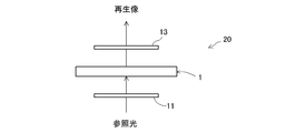
- FIG. 8 shows another form of the holography device 20.
- the thin plate-like spatial light modulator 1 is made translucent so that the reference light is incident from the back surface thereof and is transmitted through the three-dimensional image forming surface 3 on which the hologram is formed.
- the components of the holography device 20 reference light source, first polarizing plate 11, spatial light modulator 1, and second polarizing plate 13
- the compaction thereof is achieved. Is possible.
- FIG. 9 shows another form of the holography device 30.
- the holography device 30 includes a device 31 that can rewrite the hologram of the spatial light modulator 1.
- the rewriting device 31 includes a general-purpose spatial light modulator and a lens unit 36 such as a mother hologram specifying unit 32, an AD conversion unit 33, and a DMD 35.
- the mother hologram specified by the mother hologram specifying unit 32 is converted into a value of each pixel of the DMD 35 by the AD conversion unit 33. That is, the mother hologram is transferred to the DMD 35.
- the DMD 35 is irradiated with a laser beam for rewriting, reflected, condensed by the lens unit 36, and irradiated to the spatial light modulator 1.
- the mother hologram pattern is transferred as a pattern in the direction of the magnetization vector of the spatial light modulator 1.
- the rewriting laser beam has sufficient energy to invert the magnetization vector of the magneto-optical material of the spatial light modulator 1.
- the direction of the magnetization vector of the portion exposed on the stereoscopic image forming surface 3 can be reversed by irradiating the back surface of the spatial light modulator 1 with this laser beam.
- the pixel width of the DMD 35 is 10 ⁇ m or more, the laser beam is condensed by the lens unit 36 and the pixel width is set to 1 ⁇ m. As a result, a large viewing angle can be obtained, and thus a full parallax stereoscopic image can be obtained on the stereoscopic image forming surface 3.
- the DMD 35 and the lens unit 36 are also used as a reference light path to share components.
- a hologram is formed in a specific region of the spatial light modulator 1 and the portion is used as the three-dimensional image forming surface 3.
- the light after the lens unit 36 is obtained.
- the thin plate-shaped spatial light modulator 1 can be provided with a plurality of three-dimensional image forming surfaces 3, and the spatial light modulator 1 can be used as a hologram album.
- FIG. 10 to 14 show an embodiment of the present invention.
- FIG. 10 shows a subject to be photographed with a three-dimensional hologram. In this example, three boxes with different heights are lined up, and characters T, U, and T are printed from the front side.
- FIG. 11 shows a hologram acquisition apparatus. In this apparatus, linearly polarized light is generated by the HWP (1 / 2 ⁇ wavelength plate) 43 and the polarizing plate (PBS) 44 with respect to the amplitude of the 532 nm laser light emitted from the CW laser apparatus 41 and collimated by the lenses 45 and 46. Then, the light enters the half mirror 47.
- HWP (1 / 2 ⁇ wavelength plate
- PBS polarizing plate
- Incident light reflected by the half mirror 47 is reflected by the object 48 to be a target light for creating a hologram, while incident light passing through the half mirror 47 is reflected by the mirror 49 and becomes a reference light.
- the target light and the reference light form a hologram on the light receiving element (CCD) (see the hologram in FIG. 12), and the hologram pattern is photographed by the CCD and binarized (see the digital hologram in FIG. 12).
- the output of the light receiving element can correspond to the digital hologram pattern.
- a hologram pattern may be temporarily fixed on a photosensitive material such as a film instead of the light receiving element, and this may be photographed with a CCD camera or the like to form a digital hologram pattern.
- This digital hologram becomes a mother hologram.
- the mother hologram information thus digitized is written into the magneto-optical material via, for example, a DMD (see FIG. 9).
- the magneto-optical material (spatial light modulator) 60 in which the magnetization pattern is written in this way is set in the reproducing apparatus shown in FIG.
- FIG. 4 it is possible to reproduce an image that is visible with diffracted light.
- the target light and the reference light are made parallel and perpendicularly incident on the light receiving surface of the light receiving element to generate a hologram.
- the apparatus for hologram acquisition is simplified by making the reference beam and the target beam parallel.
- the obtained hologram pattern is digitized via a CCD or the like. If the digitized hologram pattern is written on the magneto-optical material corresponding to the CCD pixel, the reproducing apparatus can reproduce the image simply by irradiating the magneto-optical material with reference light. . In this respect, the reproduction apparatus becomes simple, and the speed of image reproduction can be increased.
- FIG. 14 when comparing the photograph at the left end with the photograph at the right end, the position of the letter “T” located below the letter “U” is shifted to the left and right. Thereby, it can be seen that the stereoscopic image is reproduced by the reproducing apparatus of FIG.
Landscapes
- Physics & Mathematics (AREA)
- General Physics & Mathematics (AREA)
- Nonlinear Science (AREA)
- Engineering & Computer Science (AREA)
- Optics & Photonics (AREA)
- Power Engineering (AREA)
- Computing Systems (AREA)
- Theoretical Computer Science (AREA)
- Holo Graphy (AREA)
- Optical Modulation, Optical Deflection, Nonlinear Optics, Optical Demodulation, Optical Logic Elements (AREA)
- Optical Recording Or Reproduction (AREA)
Abstract
Priority Applications (2)
| Application Number | Priority Date | Filing Date | Title |
|---|---|---|---|
| JP2013518166A JP6210549B2 (ja) | 2011-05-31 | 2012-05-31 | 像撮影方法、像撮影再生方法、空間光変調器、像再生装置及びデジタルホログラム形成装置。 |
| US14/122,188 US10108147B2 (en) | 2011-05-31 | 2012-05-31 | Image photography method, image photography play method, spatial lighting modulator, image play device, and digital hologram forming device |
Applications Claiming Priority (2)
| Application Number | Priority Date | Filing Date | Title |
|---|---|---|---|
| JP2011-122854 | 2011-05-31 | ||
| JP2011122854 | 2011-05-31 |
Publications (1)
| Publication Number | Publication Date |
|---|---|
| WO2012165556A1 true WO2012165556A1 (fr) | 2012-12-06 |
Family
ID=47259408
Family Applications (1)
| Application Number | Title | Priority Date | Filing Date |
|---|---|---|---|
| PCT/JP2012/064095 Ceased WO2012165556A1 (fr) | 2011-05-31 | 2012-05-31 | Procédé de photographie d'image, procédé de lecture de photographie d'image, modulateur spatial d'éclairage, dispositif de lecture d'image et dispositif de formation d'hologramme numérique |
Country Status (3)
| Country | Link |
|---|---|
| US (1) | US10108147B2 (fr) |
| JP (1) | JP6210549B2 (fr) |
| WO (1) | WO2012165556A1 (fr) |
Cited By (2)
| Publication number | Priority date | Publication date | Assignee | Title |
|---|---|---|---|---|
| JP2016218150A (ja) * | 2015-05-15 | 2016-12-22 | 株式会社村田製作所 | ホログラム記録装置及びホログラム再生装置 |
| CN108717254A (zh) * | 2018-06-01 | 2018-10-30 | 杭州光粒科技有限公司 | 一种大视角全息图制作方法及显示系统 |
Families Citing this family (4)
| Publication number | Priority date | Publication date | Assignee | Title |
|---|---|---|---|---|
| WO2019046212A1 (fr) * | 2017-08-28 | 2019-03-07 | Lawrence Livermore National Security, Llc | Rotateur de faraday refroidi au gaz et procédé |
| TR202022701A1 (tr) * | 2020-12-31 | 2022-07-21 | Orta Dogu Teknik Ueniversitesi | Kompakt holografi̇k slm spektrometre |
| PL439338A1 (pl) * | 2021-10-27 | 2023-05-02 | Politechnika Warszawska | Sposób rejestracji hologramów w progowym ośrodku optomagnetycznym |
| CN116859643A (zh) * | 2023-07-24 | 2023-10-10 | 中国科学院半导体研究所 | 空间光调制器及其制备方法 |
Citations (5)
| Publication number | Priority date | Publication date | Assignee | Title |
|---|---|---|---|---|
| JPH03150534A (ja) * | 1989-11-08 | 1991-06-26 | Fujitsu Ltd | 立体像表示装置 |
| JPH0418587A (ja) * | 1989-06-28 | 1992-01-22 | Seiko Instr Inc | 光学処理装置およびその駆動方法 |
| JPH0682626A (ja) * | 1992-03-05 | 1994-03-25 | Internatl Business Mach Corp <Ibm> | ホログラムシステムとその方法 |
| JP2001256654A (ja) * | 2000-03-13 | 2001-09-21 | Optware:Kk | 光情報記録装置、光情報再生装置、光情報記録再生装置および光情報記録媒体 |
| JP2011002522A (ja) * | 2009-06-16 | 2011-01-06 | Nippon Hoso Kyokai <Nhk> | 光変調素子ならびにこれを用いた空間光変調器、表示装置、ホログラフィ装置、ホログラム記録装置、および撮像装置 |
Family Cites Families (5)
| Publication number | Priority date | Publication date | Assignee | Title |
|---|---|---|---|---|
| JPH10312147A (ja) * | 1997-05-09 | 1998-11-24 | Ricoh Co Ltd | ホログラフィックステレオグラム作製装置 |
| KR100569632B1 (ko) | 1999-05-13 | 2006-04-10 | 가부시키가이샤 닛폰 쇼쿠바이 | 불포화 알데히드 및 불포화 카르복실산을 제조하기 위한촉매 및 이 촉매를 사용하여 불포화 알데히드 및 불포화카르복실산을 제조하기 위한 방법 |
| JP5332032B2 (ja) | 2008-06-27 | 2013-11-06 | 国立大学法人東京農工大学 | ホログラム表示装置 |
| US8808986B2 (en) * | 2008-08-27 | 2014-08-19 | Gen9, Inc. | Methods and devices for high fidelity polynucleotide synthesis |
| JP5380733B2 (ja) | 2009-07-09 | 2014-01-08 | 国立大学法人東京農工大学 | ホログラム表示装置 |
-
2012
- 2012-05-31 US US14/122,188 patent/US10108147B2/en not_active Expired - Fee Related
- 2012-05-31 JP JP2013518166A patent/JP6210549B2/ja not_active Expired - Fee Related
- 2012-05-31 WO PCT/JP2012/064095 patent/WO2012165556A1/fr not_active Ceased
Patent Citations (5)
| Publication number | Priority date | Publication date | Assignee | Title |
|---|---|---|---|---|
| JPH0418587A (ja) * | 1989-06-28 | 1992-01-22 | Seiko Instr Inc | 光学処理装置およびその駆動方法 |
| JPH03150534A (ja) * | 1989-11-08 | 1991-06-26 | Fujitsu Ltd | 立体像表示装置 |
| JPH0682626A (ja) * | 1992-03-05 | 1994-03-25 | Internatl Business Mach Corp <Ibm> | ホログラムシステムとその方法 |
| JP2001256654A (ja) * | 2000-03-13 | 2001-09-21 | Optware:Kk | 光情報記録装置、光情報再生装置、光情報記録再生装置および光情報記録媒体 |
| JP2011002522A (ja) * | 2009-06-16 | 2011-01-06 | Nippon Hoso Kyokai <Nhk> | 光変調素子ならびにこれを用いた空間光変調器、表示装置、ホログラフィ装置、ホログラム記録装置、および撮像装置 |
Cited By (3)
| Publication number | Priority date | Publication date | Assignee | Title |
|---|---|---|---|---|
| JP2016218150A (ja) * | 2015-05-15 | 2016-12-22 | 株式会社村田製作所 | ホログラム記録装置及びホログラム再生装置 |
| CN108717254A (zh) * | 2018-06-01 | 2018-10-30 | 杭州光粒科技有限公司 | 一种大视角全息图制作方法及显示系统 |
| CN108717254B (zh) * | 2018-06-01 | 2020-08-04 | 杭州光粒科技有限公司 | 一种大视角全息图制作方法及显示系统 |
Also Published As
| Publication number | Publication date |
|---|---|
| JP6210549B2 (ja) | 2017-10-11 |
| US10108147B2 (en) | 2018-10-23 |
| US20140253986A1 (en) | 2014-09-11 |
| JPWO2012165556A1 (ja) | 2015-02-23 |
Similar Documents
| Publication | Publication Date | Title |
|---|---|---|
| JP6210549B2 (ja) | 像撮影方法、像撮影再生方法、空間光変調器、像再生装置及びデジタルホログラム形成装置。 | |
| US8644123B2 (en) | Hologram generating device and hologram printer | |
| JP4524689B2 (ja) | ホログラム再生装置およびホログラム再生方法並びに位相変調素子 | |
| JP2009536747A5 (fr) | ||
| JP2007164862A (ja) | ホログラム記録方法及びホログラム記録装置 | |
| JP3729477B2 (ja) | ホログラム作成装置および方法 | |
| TW449741B (en) | System and method for steering focal plane data to access data locations in a holographic memory | |
| JP2017062373A (ja) | 画像再生装置 | |
| US7952975B2 (en) | Optical reproduction device, optical recording/reproduction device, and optical reproduction method | |
| Lu et al. | Compact, reliable asymmetric optical configuration for cost-effective fabrication of multiplex dot matrix hologram in anti-counterfeiting applications | |
| JP2013195802A (ja) | ホログラフィックステレオグラム記録装置及び方法 | |
| US8804474B2 (en) | Optical information recording/reproducing apparatus | |
| TW200823895A (en) | Method and system for parallel optical decoding of digital phase image to intensity image | |
| JP2007149253A (ja) | ホログラフィ用光ピックアップ装置 | |
| JP3980822B2 (ja) | 画像投射装置および画像投射方法 | |
| Zacharovas et al. | One-step 3D full colour and achromatic transmission holograms digitally printed using a 440nm pulsed laser for embossed applications | |
| JP2022126985A (ja) | 回折効率最適化システムおよび回折効率最適化方法 | |
| JP2017032947A (ja) | ホログラフィックステレオグラム作成装置及び拡散部材 | |
| JP2007193874A (ja) | 光情報記録装置および光情報再生装置 | |
| EP1766480A1 (fr) | Dispositif optique, systeme optique et procede de fabrication d'un element optique holographique | |
| CN214375860U (zh) | 一种空间光调制器零级光的分离系统 | |
| JP2008027490A (ja) | 情報記録再生装置及び情報再生方法 | |
| JP4234112B2 (ja) | ホログラム作成装置 | |
| JP5298267B2 (ja) | 光情報再生装置及び再生方法 | |
| JP2006317886A (ja) | ホログラム記録再生装置 |
Legal Events
| Date | Code | Title | Description |
|---|---|---|---|
| 121 | Ep: the epo has been informed by wipo that ep was designated in this application |
Ref document number: 12793108 Country of ref document: EP Kind code of ref document: A1 |
|
| DPE1 | Request for preliminary examination filed after expiration of 19th month from priority date (pct application filed from 20040101) | ||
| ENP | Entry into the national phase |
Ref document number: 2013518166 Country of ref document: JP Kind code of ref document: A |
|
| WWE | Wipo information: entry into national phase |
Ref document number: 14122188 Country of ref document: US |
|
| NENP | Non-entry into the national phase |
Ref country code: DE |
|
| 122 | Ep: pct application non-entry in european phase |
Ref document number: 12793108 Country of ref document: EP Kind code of ref document: A1 |