WO2013145523A1 - Disque - Google Patents
Disque Download PDFInfo
- Publication number
- WO2013145523A1 WO2013145523A1 PCT/JP2013/000577 JP2013000577W WO2013145523A1 WO 2013145523 A1 WO2013145523 A1 WO 2013145523A1 JP 2013000577 W JP2013000577 W JP 2013000577W WO 2013145523 A1 WO2013145523 A1 WO 2013145523A1
- Authority
- WO
- WIPO (PCT)
- Prior art keywords
- disk
- disc
- magazine
- tray
- gear
- Prior art date
- Legal status (The legal status is an assumption and is not a legal conclusion. Google has not performed a legal analysis and makes no representation as to the accuracy of the status listed.)
- Ceased
Links
Images
















Classifications
-
- G—PHYSICS
- G11—INFORMATION STORAGE
- G11B—INFORMATION STORAGE BASED ON RELATIVE MOVEMENT BETWEEN RECORD CARRIER AND TRANSDUCER
- G11B23/00—Record carriers not specific to the method of recording or reproducing; Accessories, e.g. containers, specially adapted for co-operation with the recording or reproducing apparatus ; Intermediate mediums; Apparatus or processes specially adapted for their manufacture
- G11B23/0014—Record carriers not specific to the method of recording or reproducing; Accessories, e.g. containers, specially adapted for co-operation with the recording or reproducing apparatus ; Intermediate mediums; Apparatus or processes specially adapted for their manufacture record carriers not specifically of filamentary or web form
- G11B23/0021—Record carriers not specific to the method of recording or reproducing; Accessories, e.g. containers, specially adapted for co-operation with the recording or reproducing apparatus ; Intermediate mediums; Apparatus or processes specially adapted for their manufacture record carriers not specifically of filamentary or web form discs
- G11B23/0028—Details
- G11B23/0035—Details means incorporated in the disc, e.g. hub, to enable its guiding, loading or driving
-
- G—PHYSICS
- G11—INFORMATION STORAGE
- G11B—INFORMATION STORAGE BASED ON RELATIVE MOVEMENT BETWEEN RECORD CARRIER AND TRANSDUCER
- G11B17/00—Guiding record carriers not specifically of filamentary or web form, or of supports therefor
- G11B17/22—Guiding record carriers not specifically of filamentary or web form, or of supports therefor from random access magazine of disc records
- G11B17/225—Guiding record carriers not specifically of filamentary or web form, or of supports therefor from random access magazine of disc records wherein the disks are transferred from a fixed magazine to a fixed playing unit using a moving carriage
-
- G—PHYSICS
- G11—INFORMATION STORAGE
- G11B—INFORMATION STORAGE BASED ON RELATIVE MOVEMENT BETWEEN RECORD CARRIER AND TRANSDUCER
- G11B23/00—Record carriers not specific to the method of recording or reproducing; Accessories, e.g. containers, specially adapted for co-operation with the recording or reproducing apparatus ; Intermediate mediums; Apparatus or processes specially adapted for their manufacture
- G11B23/02—Containers; Storing means both adapted to cooperate with the recording or reproducing means
- G11B23/03—Containers for flat record carriers
- G11B23/032—Containers for flat record carriers for rigid discs
- G11B23/0323—Containers for flat record carriers for rigid discs for disc-packs
-
- G—PHYSICS
- G11—INFORMATION STORAGE
- G11B—INFORMATION STORAGE BASED ON RELATIVE MOVEMENT BETWEEN RECORD CARRIER AND TRANSDUCER
- G11B23/00—Record carriers not specific to the method of recording or reproducing; Accessories, e.g. containers, specially adapted for co-operation with the recording or reproducing apparatus ; Intermediate mediums; Apparatus or processes specially adapted for their manufacture
- G11B23/02—Containers; Storing means both adapted to cooperate with the recording or reproducing means
- G11B23/03—Containers for flat record carriers
- G11B23/0328—Containers for flat record carriers the disc having to be extracted from the cartridge for recording reproducing, e.g. cooperating with an extractable tray
-
- G—PHYSICS
- G11—INFORMATION STORAGE
- G11B—INFORMATION STORAGE BASED ON RELATIVE MOVEMENT BETWEEN RECORD CARRIER AND TRANSDUCER
- G11B7/00—Recording or reproducing by optical means, e.g. recording using a thermal beam of optical radiation by modifying optical properties or the physical structure, reproducing using an optical beam at lower power by sensing optical properties; Record carriers therefor
- G11B7/24—Record carriers characterised by shape, structure or physical properties, or by the selection of the material
- G11B7/24097—Structures for detection, control, recording operation or replay operation; Special shapes or structures for centering or eccentricity prevention; Arrangements for testing, inspecting or evaluating; Containers, cartridges or cassettes
-
- G—PHYSICS
- G11—INFORMATION STORAGE
- G11B—INFORMATION STORAGE BASED ON RELATIVE MOVEMENT BETWEEN RECORD CARRIER AND TRANSDUCER
- G11B2220/00—Record carriers by type
- G11B2220/20—Disc-shaped record carriers
- G11B2220/25—Disc-shaped record carriers characterised in that the disc is based on a specific recording technology
- G11B2220/2508—Magnetic discs
-
- G—PHYSICS
- G11—INFORMATION STORAGE
- G11B—INFORMATION STORAGE BASED ON RELATIVE MOVEMENT BETWEEN RECORD CARRIER AND TRANSDUCER
- G11B2220/00—Record carriers by type
- G11B2220/40—Combinations of multiple record carriers
- G11B2220/41—Flat as opposed to hierarchical combination, e.g. library of tapes or discs, CD changer, or groups of record carriers that together store one title
Definitions
- the present invention relates to a disk, and more particularly, to a disk having a structure capable of supporting a disk positioned one up from the bottom of the stacked disks.
- Patent Document 1 Japanese Patent Laid-Open No. 2011-204311
- the disk device of Patent Document 1 includes a magazine that stores a plurality of trays that store one disk, and a plurality of disk drives.
- the disk device of Patent Document 1 is configured to pull out an arbitrary tray from a magazine, suck and hold one disk stored in the pulled-out tray by a suction pad, and place it on the tray of an arbitrary disk drive. Has been.
- the disk device of Patent Document 1 is configured to store one disk in one tray, the number of disks stored in the magazine is small. In order to increase the number of disks stored in the magazine, it is considered effective to directly stack a plurality of disks without using a tray and reduce the number of trays.
- Patent Document 2 Japanese Patent Laid-Open No. 2000-117553.
- Patent Document 2 discloses a technique in which a claw portion is inserted between two adjacent disks so that the two disks are separated from each other, and the separated disks are sucked and held by a suction pad. Yes.
- Patent Document 2 it is not possible to reduce the time for supplying a disk to each of a plurality of disk drives. Further, when separating the stacked disks, it is necessary to insert a substrate separation claw provided on the take-out arm into a slight gap obtained by ribs formed on the disks. For this reason, the take-out arm must be positioned with high accuracy in the vertical direction, but the mechanism for that purpose must be expensive. Further, although the substrate separation claw must be thinned, it is difficult to obtain a strength that can support the disk, and there is a risk of deformation during use.
- an object is to provide a disc that can be easily and appropriately separated in a stacked state.
- a disc having a central hole has a supportable structure that can support a disk positioned one above the arbitrary disk in a stacked state with a separating claw protruding from the center hole to the outer diameter side. It is.
- the disc since the disc has a supportable structure, when the disc is supported by the separation pawl, the separation pawl does not interfere with the disc and smoothly moves up from any one disc.
- the disk located can be supported.
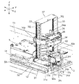
- FIG. 1 is a perspective view showing a schematic configuration of a disk device according to an embodiment of the present invention.
- FIG. 2 is a perspective view of a magazine provided in the disk device of FIG. 1. It is a magazine exploded perspective view of Drawing 2A. It is a perspective view of the picker with which the disk apparatus of FIG. 1 is provided. It is a top view which shows the structure of the drive system of the lifting platform with which the picker of FIG. 3 is provided. It is the perspective view which looked at the picker of FIG. 3 from diagonally downward.
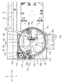
- FIG. 4 is a plan view showing a state in which the picker of FIG. 3 has moved to the front of a magazine selected from a plurality of magazines. FIG. 4 is a plan view showing how the picker of FIG.
- FIG. 4 is a plan view showing how the picker of FIG. 3 pulls out a magazine tray from a magazine.
- FIG. 4 is a plan view showing how the picker of FIG. 3 pulls out a magazine tray from a magazine.
- FIG. 4 is a plan view showing how the picker of FIG. 3 pulls out a magazine tray from a magazine.
- FIG. 4 is a plan view showing how the picker of FIG. 3 pulls out a magazine tray from a magazine.
- FIG. 4 is a plan view showing how the picker of FIG. 3 pulls out a magazine tray from a magazine.
- FIG. 4 is a plan view showing a state where the picker of FIG. 3 has pulled out a magazine tray from the magazine.
- FIG. 4 is a plan view showing a state in which the picker of FIG.
- FIG. 3 transports a magazine tray to the vicinity of a plurality of disk drives.
- FIG. 4 is a perspective view showing a state in which the picker of FIG. 3 transports a magazine tray to the vicinity of a plurality of disk drives.
- FIG. 4 is a perspective view showing a state in which the picker of FIG. 3 has moved the magazine tray above a lifter included in the disk device of FIG. 1.
- FIG. 2 is an exploded perspective view showing a state where a magazine tray guide of a lifter included in the disk device of FIG. 1 is removed.
- FIG. 2 is an assembled perspective view showing a state where a magazine tray guide of a lifter included in the disk device of FIG. 1 is removed. It is a perspective view of the carrier with which the disk apparatus of FIG. 1 is provided.
- FIG. 20 is an exploded perspective view of the carrier of FIG. 19. It is the perspective view which looked at the carrier of FIG. 19 from diagonally downward. It is a disassembled perspective view of the carrier of FIG.
- FIG. 20 is an exploded perspective view of the disc chuck unit included in the carrier of FIG. 19, as viewed obliquely from above.
- FIG. 20 is an exploded perspective view of the disc chuck unit included in the carrier of FIG. 19, as viewed obliquely from below.
- FIG. 24 is an enlarged perspective view of two separator hooks and two bottom hooks provided in the disc chuck unit of FIG. 23.
- FIG. 24 is a perspective view showing a state in which a spindle head included in the disc chuck unit of FIG. 23 is fixed to a lower end portion of a spindle shaft with a screw.
- FIG. 24 is a perspective view of a spindle head provided in the disc chuck unit of FIG. 23.
- FIG. 24 is an exploded perspective view of a camshaft unit included in the disc chuck unit of FIG. 23. It is the perspective view which looked at two cam plates with which the camshaft unit of FIG. 28 is provided from diagonally downward. It is a figure which shows a mode that the drive pin of one separator hook slides the cam groove formed in the upper surface of one cam plate.
- FIG. 34 is a diagram showing a state in which each hook shown in FIGS.
- FIG. 34 is a diagram showing a state in which each hook shown in FIGS. 30A to 33D slides in a corresponding cam groove, paying attention to the positional relationship between the camshaft and each hook.
- FIG. 34 is a diagram showing a state in which each hook shown in FIGS. 30A to 33D slides in a corresponding cam groove, paying attention to the positional relationship between the camshaft and each hook.
- FIG. 34 is a diagram showing a state in which each hook shown in FIGS. 30A to 33D slides in a corresponding cam groove, paying attention to the positional relationship between the camshaft and each hook.
- FIG. 34 is a diagram showing a state in which each hook shown in FIGS. 30A to 33D slides in a corresponding cam groove, paying attention to the positional relationship between the camshaft and each hook.
- FIG. 20 is a diagram schematically showing how the carrier of FIG. 19 separates one disc from a plurality of discs.
- FIG. 20 is a diagram schematically showing how the carrier of FIG. 19 separates one disc from a plurality of discs.
- FIG. 20 is a diagram schematically showing how the carrier of FIG. 19 separates one disc from a plurality of discs.
- FIG. 20 is a diagram schematically showing how the carrier of FIG. 19 separates one disc from a plurality of discs.
- FIG. 20 is a diagram schematically showing how the carrier of FIG. 19 separates one disc from a plurality of discs.
- FIG. 20 is a diagram schematically showing how the carrier of FIG. 19 separates one disc from a plurality of discs.
- FIG. 20 is a diagram schematically showing how the carrier of FIG. 19 separates one disc from a plurality of discs.
- FIG. 20 is a diagram schematically showing how the carrier of FIG. 19 separates one disc from a plurality of discs.
- FIG. 20 is a diagram schematically showing how the carrier of FIG. 19 separates one disc from a plurality of discs.
- FIG. 20 is a diagram schematically showing how the carrier of FIG. 19 separates one disc from a plurality of discs. It is sectional drawing which shows the state which penetrated the shaft in a disk drive in the center hole of a disk. It is sectional drawing which shows the disk by which the escape part was formed in the upper surface inner peripheral part by the taper surface. It is sectional drawing which shows the disk by which the escape part was formed in the upper surface inner peripheral part by the taper surface and the horizontal surface.
- the disc can be configured as follows.
- a disc having a central hole The inner circumference has a supportable structure that can support a disk positioned one above the arbitrary disk in a stacked state with a separating claw protruding from the center hole to the outer diameter side. It is.
- the supportable structure when the separation claw protrudes from the center hole of the disk to the outer diameter side, the supportable structure is used to smoothly and smoothly move the disk positioned one above the arbitrary one disk. Can be supported.
- the supportable structure is constituted by an escape portion formed on the inner peripheral portion of the upper surface of the disk.
- the supportable structure is constituted by a relief portion formed on the inner peripheral portion of the lower surface of the disk.
- the disk positioned one above the lowermost part can be supported by the separation claw with a simple configuration in which the relief part is formed on the disk.
- the escape portion has a horizontal plane on the inner peripheral side.
- the fourth aspect it is possible to form a wide gap between the disks adjacent in the vertical direction from the inner peripheral surface side toward the outer diameter direction. Therefore, the position accuracy of the separation claw in the vertical direction is not so required. Further, even a thick separation claw can be used.
- the supportable structure is constituted by a recess formed on the inner peripheral surface of the disk.
- the concave portion is formed on the inner peripheral surface of the disc, if the separation claw is arranged on the inner peripheral side of the disc and protrudes to the outer diameter side, the concave portion can be easily positioned in the concave portion.
- the disc can be supported. Since the recess is only formed on the inner peripheral surface of the disk, even a disk having a memory layer on both sides can be supported by the separation claw.
- the supportable structure is constituted by a protruding portion protruding from the inner peripheral surface of the disk.
- the projecting portion is formed on the inner peripheral surface of the disk, if the separating claw is arranged on the inner side of the projecting portion and projects to the outer diameter side, the projecting portion can easily be used. Can be supported. Since the protruding portion is formed only on the inner peripheral surface of the disc, even a disc having a storage layer on both sides can be supported by the separation claw.
- the supportable structure is constituted by a rib protruding from at least one of the upper surface and the lower surface of the inner periphery of the disk.
- the separation claw is supported from the inside of the protruding portion or the rib to the inside of the inner peripheral surface of the disk on the outer diameter side, thereby supporting the disc via the protruding portion or the rib. Can do.
- the disk device can be configured as follows.
- the disc is provided with a supportable structure, the disc positioned one level above the lowermost portion can be easily and smoothly supported by the separation claw. In addition, it is possible to reduce the time required to supply the disk to each of the plurality of disk drives.
- the carrier includes a spindle unit that is inserted into a center hole of the disc,
- the separation claw moves between a retracted position for retracting to the inside of the spindle unit and a projecting position that protrudes into the escape part of the disk and can support the inner peripheral part of the lower surface of the disk located one level above the lowest part. It is possible.
- the separation claw can be moved from the retracted position to the projecting position, and the separation claw can be separated from the lowermost part without interfering with the stacked disks. It is possible to easily and smoothly support the inner peripheral portion of the lower surface of the upper disk.
- the separation pawl is movable between the retracted position and the protruding position in conjunction with the rotational operation of the camshaft inserted inside the spindle unit.
- the separation claw can be moved between the retracted position and the protruding position only by rotating the camshaft.
- the carrier is A spindle unit inserted into the center hole of the disc;
- the first separation claw and the support claw are A storage position in which both the separation claw and the support claw are retracted inside the spindle unit;
- the disk one level higher than the lowermost part is supported by the separation claw at the separation position, and then the support claw is moved at the switching position. By retracting, only the lowermost disk can be separated.
- the separation claw and the support claw move in the order of the storage position, the support position, the switching position, and the separation position in accordance with the rotation of the camshaft inserted inside the spindle unit. It is possible.
- the separation pawl and the support pawl are sequentially moved in the order of the storage position, the support position, the switching position, and the separation position, so that the disc positioned at the bottom is securely Can be separated.
- the separation claw and the support claw are When the spindle unit is inserted into the center hole of the disk, it is located at the storage position, When the spindle unit is inserted into the center hole until the support claw is positioned below the lowermost disk, the support claw is moved from the storage position to the support position, so that the support claw is moved to the lowermost disk. Support the inner periphery of the lower surface, When the support claw supports the lowermost disk, it moves to the switching position, When the support claw is transported above the tray while supporting the lowermost disk, the support claw is moved from the switching position to the separation position.
- the separation claw and the support claw can be appropriately protruded or retreated with respect to the disk in accordance with the raising / lowering position of the spindle unit, and only the disk positioned at the lowermost part is reliably separated. Is possible.
- the separation claw has an inclined surface formed so as to increase in thickness downward from the outer peripheral side toward the inner peripheral side, and when the separation claw is positioned at the separation position, It protrudes to the outside of the spindle unit as compared to when it is positioned at the position, and the disk positioned at the lowermost portion is pressed downward by the inclined surface.
- the lowermost disk can be pushed by the pressing surface only by projecting the separation pawl outward. Can be separated easily and reliably.
- FIG. 1 is a perspective view showing a schematic configuration of the disk device.
- the lower left side in FIG. 1 is referred to as “device front”, and the upper right side in FIG. 1 is referred to as “device rear”.
- the disk device includes two magazine stockers 1 and 1.
- the two magazine stockers 1 and 1 are provided on the bottom chassis 11 so as to face each other in the apparatus width direction Y.
- FIG. 1 the illustration of one (front side) magazine stocker 1 is omitted.
- FIG. 1 illustration of the top plate and the partition plate of the magazine stocker 1 is omitted.
- Each magazine stocker 1 stores a plurality of magazines 2.
- Each magazine 2 has a magazine tray 21 for storing a plurality of (for example, 12) disks. Between the two magazine stockers 1 and 1, there is provided a picker 3 that pulls out the magazine tray 21 from one magazine 2 selected from the plurality of magazines 2 and holds the magazine tray 21.
- the picker 3 is configured to transport the held magazine tray 21 to the vicinity of a plurality of disk drives 4 arranged at the rear of the apparatus.
- the picker 3 is integrally provided with a lifter 5 that pushes out a plurality of discs 100 from the magazine tray 21.
- the disk drive 4 is a device that records or reproduces information on the disk 100.
- the disk drive 4 is a tray type disk drive that loads a disk using a tray 4a (see FIG. 44).
- the plurality of disk drives 4 are stacked in the apparatus height direction Z, and are arranged adjacent to the magazine stockers 1 and 1 at the rear of the apparatus.
- a carrier 106 is provided between the plurality of disk drives 4 stacked adjacent to one magazine stocker 1 and the plurality of disk drives 4 stacked adjacent to the other magazine stocker 1. Yes.
- the carrier 106 holds the plurality of discs 100 pushed out by the lifter 5 in a stacked state, and above the tray 4a ejected from any disc drive 4, one disc 100 out of the held plurality of discs. And the separated disk 100 is placed on the tray 4a.
- the tray 4a is collected in the disk drive 4, and a center cone 110 of a spindle motor (not shown) is inserted into the center hole 100a of the loaded disk 100 as shown in FIG.
- the center cone 110 includes a cylindrical surface 110a that engages with the center hole 100a of the disk 100, and a conical surface 110b that gradually decreases in outer diameter from the cylindrical surface 110a toward the tip.
- the disc 100 separated by the conical surface 110b is guided through the center hole 100a, and the disc 100 is centered by the cylindrical surface 110a.
- the upper surface of the disk 100 is the upper surface of the disk, and the lower surface is the lower surface of the disk.
- a recording surface is formed on the lower surface of the disk.
- FIG. 45A the configuration of the escape portion of the disk 100 is shown in FIG. 45A, which will be described later. However, FIG. 45B, FIG.
- the electric circuit and power source 7 is provided with a control unit that controls the operation (motor, etc.) of each device such as the picker 3, the disk drive 4, and the carrier 106.
- the control unit is connected to, for example, a host computer that manages data. Based on the operator's instruction, the host computer sends a command to the control unit so as to perform operations such as writing or reading data to or from the designated magazine 2.
- the control unit controls the operation of each device such as the picker 3, the disk drive 4, and the carrier 106 in accordance with the command.
- the magazine stocker 1 is provided along a guide rail 12 that slidably guides the picker 3.
- the guide rail 12 is provided so as to extend in the apparatus depth direction X (longitudinal direction of the magazine stocker 1).
- a handle 13 is provided on the side surface of the magazine stocker 1 on the front side of the apparatus. By pulling the handle 13, the magazine stocker 1 can be moved forward of the apparatus.
- Each magazine stocker 1 includes a partition plate (not shown) formed in a lattice shape when viewed from the apparatus width direction Y.
- the magazine 2 is accommodated in each space surrounded by the partition plate.
- the magazine 2 includes a magazine tray 21 and a substantially rectangular parallelepiped case 22 that houses the magazine tray 21.
- an opening 22 a into which the magazine tray 21 can be inserted and removed is provided on the front surface (one side surface) of the case 22.
- the outer shape of the magazine tray 21 is formed in a substantially rectangular shape in plan view.
- the magazine tray 21 stores a plurality of discs 100 in a state where they are stacked in close contact with each other. Cut portions 21 a and 21 a are formed at both corner portions located on the back side of the case 22 when the magazine tray 21 is stored in the case 22. Further, when the magazine tray 21 is housed in the case 22, the entire side surface 21b located on the back side of the case 22 is formed in an arc shape including the cut portions 21a and 21a.
- the disc 100 has a center hole 100a, and an upper surface side annular rib 101a and a lower surface side annular rib 101b (the outer periphery side is not shown) are respectively formed on the inner and outer peripheral sides of the upper and lower surfaces.
- a supportable structure is formed on the inner periphery of the disk 100.
- Various structures can be adopted as the supportable structure.
- it is constituted by an escape portion 102 formed by a tapered surface 102a that gradually spreads upward on the inner peripheral portion of the upper surface of the disk 100 upward.
- the gap G to be formed is a gap (0.15 mm) formed by the annular ribs 101a and 101b and a gap (0.15 mm) formed by the tapered surface 102a ( 0.65 mm) can be added (0.8 mm).
- it is constituted by an escape portion 102 formed so that a horizontal surface 102b extends from the middle of the tapered surface 102a to the inner diameter side.
- the gap G formed with respect to the thickness T (1.2 mm) of the disk 100 is the gap formed by the annular ribs 101a and 101b, that is, the height dimension h1 (0 of the annular rib 101a).
- FIG. 45C it is comprised by the relief part 102 formed of the horizontal surface 102b and the cylindrical surface 102c.
- the specific vertical dimension is the same as that shown in FIG. 45B.
- FIGS. 45A to 45C since the centering is performed on the lower side of the disk 100, the escape portion 102 is formed on the upper side.
- FIG. 45D an annular recess 103 that is recessed toward the outer diameter side is formed on the inner peripheral surface of the disk 100.
- the recess 103 is formed at the center with respect to the thickness direction of the disk 100.
- an annular protrusion 104 that protrudes toward the inner diameter side is formed on the inner peripheral surface of the disk 100.
- the protrusion 104 is formed at the center with respect to the thickness direction of the disk 100.
- the protrusion 104 does not necessarily have to be connected in a ring shape.
- what is necessary is just to utilize the internal peripheral surface of the protrusion part 104 as a hole for centering.
- the upper surface side annular rib 101a of the lower disk 100B contacts the lower surface side annular rib 101b of the upper disk 100A.
- a gap is formed between the disks 100A and 100B.
- the clearance between the disks 100A and 100B is further widened by the escape portion. Therefore, even if the separation claw (claw portions 164Ac and 164Bc of the separator hooks 164A and 164B) described later is not so high in positioning accuracy, the separation claw can be surely entered into the gap between the discs 100A and 100B. it can. 45B, in particular, the relief portion 102 having the configuration shown in FIG. 45C is widened toward the outer diameter side while maintaining the vertical gap on the inner peripheral surface side.
- 45D and the protrusion 104 shown in FIG. 45E have the same shape on the upper and lower surfaces, which is effective for the disc 100 having the storage layers on both sides.
- the escape portion 102 is not only for avoiding interference with the separation claw when supporting the disc 100A positioned one above, but also, for example, on the inner peripheral portion of the lower surface of the disc 100 as shown in FIG. It is also possible to form a space for supporting the disc 100 itself by forming the relief portion 102 having a configuration in which the horizontal surface 103e extends to the inner diameter side from the middle of the tapered surface 103d similar to the configuration shown in FIG. 45B. It is.
- Notches 21c and 21c are formed at both corners located on the front side of the case 22 when the magazine tray 21 is stored in the case 22.
- engaging recesses 21d and 21d are formed on the inner side of the notches 21c and 21c to be engaged with a pair of hooks 35 and 35 described later.
- the magazine tray 21 is provided with a core rod 23 that is inserted into a central hole 100a provided in each of the plurality of disks 100 and restricts movement of each disk 100 in the surface direction.
- the core rod 23 prevents each disk 100 from being damaged by the movement of each disk 100 in the surface direction.
- the core rod 23 is provided with an engaging portion 23a with which a spindle head 67b of a disk chuck unit 62 described later is engaged.
- At least one hole 21e into which a lift pin 52a of the lifter 5 described later is inserted is provided.
- three holes 21e are provided at intervals of 120 degrees. Further, the three holes 21 e are provided at positions facing the non-recording / reproducing area on the inner peripheral portion of the disc 100 when the disc 100 is inserted into the core rod 23.
- the picker 3 includes a traveling base 31. As shown in FIG. 3, a carriage 31 a that slidably moves the guide rail 12 is attached to one magazine stocker 1 side of the traveling base 31. In addition, a roller 31b is attached to the other magazine stocker 1 side of the traveling base 31 as shown in FIG.
- the traveling base 31 is provided with a picker motor 31c that generates a driving force for moving the picker 3 in the apparatus depth direction X, as shown in FIG.
- a reduction gear 31d meshes with the motor gear 31i press-fitted into the drive shaft of the picker motor 31c.
- the reduction gear 31d meshes with the pinion gear 31e.
- the pinion gear 31e meshes with the rack 14 provided so as to extend in the apparatus depth direction X adjacent to the guide rail 12.
- a stepping motor is used as the picker motor 31c.
- the picker 3 By giving a predetermined pulse to the picker motor 31c, the picker 3 can be moved in front of the predetermined magazine 2.
- a picker base 31h made of resin is attached to the traveling base 31 made of sheet metal.
- the picker base 31h is provided with a turntable 32 that is rotatable about a rotation shaft 32a extending in the apparatus height direction Z.
- the picker base 31h is provided with a turntable motor 31f that generates a driving force for rotating the turntable 32.
- a reduction gear 31g is meshed with the motor gear 31j press-fitted into the drive shaft of the turntable motor 31f.
- the reduction gear 31g meshes with a turntable gear 32b provided on the outer periphery of the turntable 32.
- the turntable 32 is provided with a pair of elevating rails 33, 33 extending in the apparatus height direction Z and facing each other.
- a lifting platform 34 is provided between the pair of lifting rails 33, 33.
- the rotary table 32 is provided with a lift motor 32c that generates a driving force for moving the lift 34 up and down.
- a relay gear 32d is engaged with the motor gear 32k press-fitted into the drive shaft of the elevator motor 32c.
- the connecting shaft gear 32e meshes with the relay gear 32d.
- a connecting shaft 32f passes through the center of the connecting shaft gear 32e.
- Worms 32g and 32g are fixed to both ends of the connecting shaft 32f.
- Each worm 32g is engaged with the relay gear 32h.
- Each relay gear 32h meshes with the lead screw gear 32i.
- Each lead screw gear 32i is fixed to a lead screw 32j.
- Each lead screw 32j is provided so as to extend in the apparatus height direction Z along the elevating rail 33.
- a nut 34a provided on the lifting platform 34 is screwed into each lead screw 32j.
- the driving force of the lifting / lowering table motor 32c When the lifting / lowering table motor 32c is driven, the driving force of the lifting / lowering table motor 32c generates the lead screw 32j via the motor gear 32k, the relay gear 32d, the connecting shaft gear 32e, the connecting shaft 32f, the worm 32g, the relay gear 32h, and the lead screw gear 32i. And the lead screw 32j rotates. As a result, the lifting platform 34 moves up and down in the apparatus height direction Z along the pair of lifting rails 33, 33.
- the lifting platform 34 includes a pair of hooks 35, 35 that can be engaged with the engaging recess 21 d of the magazine tray 21, and a mechanism that opens and closes the pair of hooks 35, 35. And a chuck 36 to be moved to.
- the lift table 34 is provided with a chuck motor 34b.
- the reduction gear 34c meshes with the motor gear 34f press-fitted into the drive shaft of the chuck motor 34b.
- the reduction gear 34c meshes with the lead screw gear 34d.
- the lead screw gear 34d is fixed to the lead screw 34e.
- the lead screw 34e is provided so as to extend in a direction orthogonal to a straight line connecting the pair of lifting rails 33, 33.
- a nut 36a fixed to the chuck 36 is screwed into the lead screw 34e.
- the driving force of the chuck motor 34b is transmitted to the nut 36a via the motor gear 34f, the reduction gear 34c, the lead screw gear 34d, and the lead screw 34e, and the chuck 36 moves along the lead screw 34e. Moving.
- the chuck 36 is configured so that the distance between the pair of hooks 35 and 35 can be adjusted. As the chuck 36 reduces the distance between the pair of hooks 35, 35, the pair of hooks 35, 35 can be engaged with the engagement recesses 21 d, 21 d of the magazine tray 21. On the other hand, when the chuck 36 widens the distance between the pair of hooks 35, 35, the engagement state between the pair of hooks 35, 35 and the engagement recesses 21 d, 21 d of the magazine tray 21 can be released.
- the pair of elevating rails 33 is attached to both side surfaces of the U-shaped angle 37.
- the upper ends of the pair of lead screws 32j are rotatably attached to the upper surface of the angle 37.
- the picker motor 31c, the rotary table motor 31f, the lift table motor 32c, and the chuck motor 34b are connected to a control unit of the electric circuit and the power source 7 via an FFC (flexible flat cable) 114 (see FIG. 1).
- the drive is controlled by.
- FIG. 6 to 12 show how the picker 3 pulls out the magazine tray 21 from the case 22.
- the traveling base 31 travels in the apparatus depth direction X and the lifting platform 34 moves up and down in the apparatus height direction Z along the pair of lifting rails 33, as shown in FIG.
- the picker 3 is moved to the front of the selected one magazine 2. Further, as shown in FIG. 7, the turntable 32 is rotated so that the chuck 36 faces the front of the magazine 2.
- the chuck 36 advances toward the magazine tray 21, and the pair of hooks 35, 35 are engaged with the engaging recesses 21d, 21d of the magazine tray 21, as shown in FIG. .
- the magazine 36 is pulled out from the case 22 when the chuck 36 is retracted from the case 22.
- the turntable 32 rotates the rotation shaft 32a. Is rotated clockwise about the center.
- the distance L1 from the apex 21f of the side surface 21b of the magazine tray 21 (the position farthest from the rotation shaft 32a) to the rotation shaft 32a is the front end 22b of the side surface of the case 22.
- the rotation table 32 becomes smaller than the distance L2 from the rotary shaft 32a, the rotary base 32 is rotated clockwise about the rotary shaft 32a.
- the magazine tray 21 rotates about the rotation shaft 32a as shown in FIGS.
- the magazine tray 21 is completely pulled out from the case 22 as shown in FIG.
- the magazine tray 21 pulled out from the case 22 is located in the vicinity of the plurality of disk drives 4 as shown in FIGS. 13 and 14, as the traveling base 31 of the picker 3 travels backward. To be transported. Thereafter, as shown in FIG. 15, the chuck 36 of the picker 3 moves forward, and the magazine tray 21 is placed at a predetermined position on the magazine tray guide 51 above the lifter 5. 14 and 15, the illustration of the front disk drive 4 is omitted.
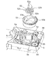
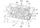
- FIG. 16 is an exploded perspective view showing a state where the magazine tray guide 51 of the lifter 5 is removed, and FIG. 17 is an assembled perspective view thereof.
- the lifter 5 includes a lift plate 52, a rotating cam 53, a drive gear 54, a relay gear 55, and a lifter motor 56.
- the elevating plate 52 includes elevating pins 52a and cam pins 52b, which are examples of rod-shaped members.
- three elevating pins 52a and three cam pins 52b are provided at intervals of 120 degrees.
- the three lifting pins 52a are provided on the magazine tray 21 as shown in FIG. 2B. It is provided at a position that coincides with the hole 21e.
- the magazine tray guide 51 is provided with three holes 51a at positions corresponding to the three lifting pins 52a.
- the three cam pins 52 b are engaged with three slits 5 a provided in the main body of the lifter 5. Each slit 5a is provided so as to extend in the apparatus height direction Z.
- Three cam grooves 53a having slopes on which the tip portions of the three cam pins 52b slide are provided on the inner peripheral surface of the rotating cam 53.
- a cam gear 53 b is provided on the outer peripheral surface of the rotating cam 53.
- the cam gear 53b meshes with the drive gear 54.
- the drive gear 54 meshes with the relay gear 55.
- the relay gear 55 meshes with a motor gear (not shown) press-fitted into the drive shaft of the lifter motor 56.
- the lifting plate 52 is lifted and lowered in the apparatus height direction Z.
- the lifter motor 56 is connected to the control unit of the electric circuit and the power source 7 via the FFC 14 (see FIG. 1), and the drive is controlled by the control unit.
- the elevating plate 52 moves up, the three elevating pins 52 a enter the magazine tray 21 through the three holes 51 a of the magazine tray guide 51 and the three holes 21 e of the magazine tray 21.
- the plurality of discs 100 are pushed out from the magazine tray 21.
- the plurality of disks 100 pushed out by the three lifting pins 52 a are held by the carrier 106.
- the carrier 106 is provided in a housing 8 that houses a plurality of (for example, 12) disk drives 4.
- the carrier 106 holds a plurality of discs pushed out by the lifter 5, separates one disc from the held plurality of discs above the tray 4 a ejected from any disc drive 4, and The separated disk is configured to be placed on the tray 4a.
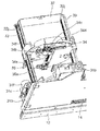
- the carrier 106 includes a moving base 161 that moves in the apparatus height direction Z, and a disc chuck unit 162 provided on the moving base 161.
- the moving base 161 includes a bush 161a connected to the ball screw 63 (see FIG. 18) and a guide bearing 161b connected to the guide shaft 64 (see FIG. 18).
- the carrier motor 65 (see FIG. 18) is driven and the ball screw 63 rotates, the moving base 161 moves in the apparatus height direction Z while being guided by the ball screw 63 and the guide shaft 64.
- a gear plate 163 provided with rotating shafts or rotating bearings of various gears to be described later is attached.
- the disk chuck unit 162 is configured to hold a plurality of disks 100 pushed out by the lifter 5 and separate the held disks 100 one by one. Specifically, as shown in FIGS. 23 and 24, the disc chuck unit 162 includes separator hooks 164A and 164B, bottom hooks 165A and 165B, a spindle unit 166, and a camshaft unit 167.
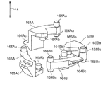
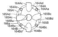
- FIG. 25 is an enlarged perspective view of the separator hooks 164A and 164B and the bottom hooks 165A and 165B.
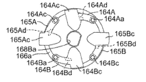
- Each of the hooks 164A to 165B is formed in a substantially lever shape and extends in the direction intersecting the apparatus height direction Z with the rotation shafts 164Aa to 165Ba and the drive pins 164Ab to 165Bb extending in the apparatus height direction Z.
- Projecting claw portions 164Ac to 165Bc are provided.
- a concave portion 100b is provided in the inner peripheral portion of the disk 100.
- the concave portion 100b is formed in a shape obtained by cutting the upper corner portion of the inner peripheral portion of the disc 100 so as to have a flat surface 100ba and an inclined surface 100bb.
- the lower surfaces of the claw portions 164Ac and 164Bc of the separator hooks 164A and 164B are formed to have a slope so that the thickness increases downward from the outer peripheral side toward the inner peripheral side.
- the upper surfaces of the claw portions 164Ac to 165Bc are formed so as to be orthogonal to the apparatus height direction Z.
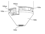
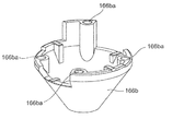
- the spindle unit 166 includes a substantially cylindrical spindle shaft 166a, a substantially truncated cone shaped spindle head 166b provided below the spindle shaft 166a, and an upper end of the spindle shaft 166a. And a provided flange 166c.
- the spindle unit 166 moves integrally with the moving base 161 by attaching the flange 166c directly or indirectly to the moving base 161.
- the diameter of the spindle shaft 166a is almost the same as or slightly smaller than the diameter of the central hole 100a of the disk 100. Therefore, the disk 100 is positioned in the radial direction with respect to the spindle shaft 166a in a state where the spindle shaft 166a is inserted into the center hole 100a of the disk 100.
- the disc 100 has an escape portion 103 formed on the inner periphery thereof, and the range of the center hole 100a guided by the spindle shaft 166a is about half of the conventional one. Therefore, even if the diameter of the spindle shaft 166a is substantially the same as the diameter of the center hole 100a of the disc 100, the spindle shaft 166a can be inserted without difficulty.
- the spindle head 166b is fixed to the lower end portion of the spindle shaft 166a with screws 166d as shown in FIG.
- Four openings 166e are formed between the spindle head 166b and the spindle shaft 166a.
- the claw portions 164Ac to 165Bc of the hooks 164A to 165B are configured to be capable of moving forward and backward through the openings 166e.
- the spindle head 166b is provided with four rotation shaft holes 166ba as shown in FIG. Further, as shown in FIG. 26, the spindle shaft 166a is provided with a rotation shaft hole 166aa at a position facing the rotation shaft hole 166ba.
- the hooks 164A to 165B are rotatably held by inserting the rotation shafts 164Aa to 165Ba into the corresponding rotation shaft holes 166aa and 166ba.
- the hooks 164A to 165B are positioned so that the upper surfaces of the claw portions 164Ac and 164Bc of the separator hooks 164A and 164B are approximately one disk higher than the upper surfaces of the claw portions 165Ac and 165Bc of the bottom hooks 165A and 165B. Retained respectively. Further, the separator hook 164A and the separator hook 164B are held at positions that are 180 degrees out of phase in the circumferential direction of the spindle unit 166, and the bottom hook 165A and the bottom hook 165B are 180 degrees out of phase in the circumferential direction of the spindle unit 166. It is held at a shifted position.
- the claw portions 164Ac and 164Bc of the separator hooks 164A and 164B constitute a separation claw that can support the inner peripheral portion of the lower surface of the disk 100 one level above the bottom.
- the claw portions 165Ac and 165Bc of the bottom hooks 165A and 165B constitute a support claw capable of supporting the inner peripheral portion of the lower surface of the disk 100 located at the lowermost portion.
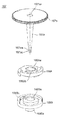
- the camshaft unit 167 includes a substantially cylindrical camshaft 167a, a cam gear 167b provided at the upper end portion of the camshaft 167a, and a cam plate 168A provided at the lower end portion of the camshaft 167a. 168B.
- Rotating shaft hole 167ba is provided at the center of cam gear 167b.
- the rotation shaft 163a provided on the gear plate 163 is inserted into the rotation shaft hole 167ba.
- the cam gear 167b meshes with the relay gear 170 as shown in FIG.
- the relay gear 170 is composed of, for example, two gears, and a rotation shaft hole 170a is provided at each central portion.
- a rotation shaft 163b provided on the gear plate 163 is inserted into the rotation shaft hole 170a.
- the relay gear 170 meshes with a motor gear 171 a that is press-fitted into a drive shaft of a disc chuck motor 171 provided on the moving base 161.
- the driving force of the disc chuck motor 171 is transmitted to the camshaft 167a via the motor gear 171a, the relay gear 170, and the cam gear 167b, and the camshaft 167a rotates about the rotation shaft 163a. .
- an engaging portion 167aa that engages with the cam plate 168A and an engaging portion 167ab that engages with the cam plate 168B are provided at the lower end of the cam shaft 167a.
- the engaging portions 167aa and 167ab are each formed in a D-shaped cross section.
- a D-shaped rotation shaft hole 168Aa is provided at the center of the cam plate 168A.
- the cam plate 168A is configured to be rotatable integrally with the camshaft 167a by engaging the engaging portion 167aa of the camshaft 167a with the rotating shaft hole 168Aa.
- a D-shaped rotation shaft hole 168Ba is provided at the center of the upper surface of the cam plate 168B.
- the cam plate 168B is configured to be rotatable integrally with the camshaft 167a by engaging the engaging portion 167ab of the camshaft 167a with the rotating shaft hole 168Ba.
- Rotating shaft 168Bb is provided at the center of the lower surface of cam plate 168B.
- the rotation shaft 168Bb is inserted into a rotation bearing 166ab provided at the lower end portion of the spindle shaft 166a as shown in FIG.
- the rotation shaft 168 ⁇ / b> Bb is positioned coaxially with the rotation shaft 163 a of the gear plate 163.
- the upper surface of the cam plate 168A is provided with a cam groove 168Ab (see FIG. 28) in which the drive pin 164Ab of the separator hook 164A slides when the cam shaft 167a rotates.
- 30A to 30D show how the drive pin 164Ab of the separator hook 164A slides in the cam groove 168Ab.
- the lower surface of the cam plate 168A is provided with a cam groove 168Ac (see FIG. 29) through which the drive pin 164Bb of the separator hook 164B slides when the cam shaft 167a rotates.
- FIGS. 31A to 31D show how the drive pin 164Bb of the separator hook 164B slides in the cam groove 168Ac.
- the cam groove 168Ac has a mirror-symmetrical shape with the cam groove 168Ab, and is provided at a position shifted in phase by 180 degrees in the circumferential direction of the spindle unit 166.
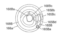
- the upper surface of the cam plate 168B is provided with a cam groove 168Bc (see FIG. 28) through which the drive pin 165Bb of the bottom hook 165B slides when the cam shaft 167a rotates.
- 32A to 32D show how the drive pin 165Bb of the bottom hook 165B slides in the cam groove 168Bc.
- the lower surface of the cam plate 168B is provided with a cam groove 168Bd (see FIG. 29) in which the drive pin 165Ab of the bottom hook 165A slides when the cam shaft 167a rotates.
- 33A to 33D show how the drive pin 165Ab of the bottom hook 165A slides in the cam groove 168Bd.
- the cam groove 168Bd has a mirror-symmetrical shape with the cam groove 168Bc, and is provided at a position shifted in phase by 180 degrees in the circumferential direction of the spindle unit 166.
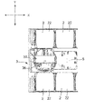
- 34A to 34D are diagrams showing the positional relationship between the camshaft 167a and the four hooks 164A to 165B.
- the separator hook 164A and the separator hook 164B are arranged such that the claw portions 164Ac and 164Bc are positioned inside the spindle shaft 166a (see FIGS. 34A and 34B) and the outside of the spindle shaft 166a as the cam shaft 167a rotates. (See FIG. 34C) and a position further outside the spindle shaft 166a (see FIG. 34D).
- the separator hooks 164A and 164B are provided with stoppers 164Ad and 164Bd in order to restrict the rotation range.
- the position shown in FIG. 34A where all the hooks 164A to 165B are located inside the spindle shaft 166a is referred to as a storage position.
- the position shown in FIG. 34B where only the bottom hooks 165A and 165B are located outside the spindle shaft 166a is referred to as a support position.
- the position shown in FIG. 34C where all the hooks 164A to 165B are located outside the spindle shaft 166a is referred to as a switching position.
- the position shown in FIG. 34D where the separator hooks 164A, 164B are located further outside the spindle shaft 166a and the bottom hooks 165A, 165B are located inside the spindle shaft 166a is referred to as a separation position.
- the operation of the carrier 106 separating one disk from a plurality of disks and placing the separated disk on the tray 4a of the disk drive 4 will be described with reference to FIGS. 35 to 43, the claw portions 164Ac and 164Ad of the separator hooks 164A and 164B and the claw portions 165Ac and 165Bc of the bottom hooks 165A and 165B are illustrated on the same cross section for convenience of explanation.
- the description starts from a state in which the elevating pins 52a push out the plurality of discs 100 from the magazine tray 21.
- each of the hooks 164A to 165B is located at the storage position (see FIG. 34A).
- the moving base 161 is raised, and the upper surfaces of the claw portions 165Ac and 165Bc of the bottom hooks 165A and 165B come into contact with the inner peripheral portion of the lowermost disc 100 to support all the discs 100.
- the engagement between the spindle head 166b and the engaging portion 23a (see FIG. 2B) of the core rod 23 is released.
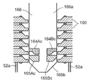
- the claw portions 164Ac, 164Bc of the separator hooks 164A, 164B are gaps formed between the lowermost disc 100B and the disc 100A one above it, that is, the concave portion 100b of the lowermost disc 100B which is an escape portion. Is positioned so as to be insertable.
- the disc chuck motor 171 (see FIG. 21) is further driven, and the cam shaft 167a further rotates in the forward direction.
- the hooks 164A to 165B move from the support position (see FIG. 34B) to the switching position (see FIG. 34C).
- the claw portions 164Ac and 164Bc of the separator hooks 164A and 164B are inserted into the gap between the lowermost disc 100B and the disc 100A positioned one above. As described above, this gap is widened by the concave portion 100b (relief portion) formed in the lowermost disk 100.
- the claws 164Ac and 164Bc can surely enter the recesses 100b. Can do.
- the picker 3 moves to the front of the apparatus, and the magazine tray 21 is withdrawn from the vicinity of the disk drive 4. Thereafter, the tray 4a of the disk drive 4 is discharged.
- the moving base 161 is lowered so that the plurality of disks 100 held by the spindle unit 166 are positioned above (for example, directly above) the tray 4a.
- the disc chuck motor 171 is further driven, and the camshaft 167a further rotates in the forward direction.
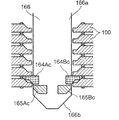
- the hooks 164A to 165B move from the switching position (see FIG. 34C) to the separation position (see FIG. 34D), and the claw portions 165Ac and 165Bc of the bottom hooks 165A and 165B are moved to the spindle as shown in FIG. It moves to a position inside the shaft 166a.
- the lowermost disk 100 falls by its own weight and is placed on the tray 4a.
- the separator hooks 164A and 164B protrude further outward from the spindle shaft 166a, and the slopes formed on the lower surfaces of the claw portions 164Ac and 164Bc of the separator hooks 164A and 164B press the lowermost disc 100 downward, It functions to assist the disc 100 falling by its own weight. Further, the upper surfaces of the claw portions 164Ac and 164Bc of the separator hooks 164A and 164B are in contact with the inner peripheral portion of the lowermost disc 100 of the remaining discs to support the remaining discs 100.
- the moving base 161 of the lowermost disc 100 placed on the tray 4a is raised so that the spindle unit 166 and the tray 4a do not come into contact with each other. Thereafter, the tray 4 a is carried into the disk drive 4. Thereafter or simultaneously with this, the tray 4a of the disk drive 4 facing the disk drive is ejected (not shown).
- the disc chuck motor 171 is reversely driven, and the camshaft 167a rotates in the reverse direction.
- the hooks 164A to 165B move from the separation position (see FIG. 34D) to the switching position (see FIG. 34C), and the claw portions 165Ac and 165Bc of the bottom hooks 165A and 165B are moved to the spindle as shown in FIG. It moves to a position outside the shaft 166a.
- the disc chuck motor 171 is further reversely driven, and the camshaft 167a further rotates in the reverse direction.
- the hooks 164A to 165B move from the switching position (see FIG. 34C) to the support position (see FIG. 34B).
- the claws 164Ac and 164Bc of the separators 164A and 164B Move to a position inside 166a.
- the remaining disk 100 supported by the upper surfaces of the claw portions 164Ac and 164Bc of the separator hooks 164A and 164B falls due to its own weight and is supported by the upper surfaces of the claw portions 165Ac and 165Bc of the bottom hooks 165A and 165B.
- the disc chuck motor 171 (see FIG. 21) is driven, and the camshaft 167a rotates in the forward direction.
- the hooks 164A to 165B move from the support position (see FIG. 34B) to the switching position (see FIG. 34C), and as shown in FIG. 39, the claws 164Ac and 164Bc of the separator hooks 164A and 164B It is inserted into the recess 100b of the lower disk 100.
- the moving base 161 is lowered so that the plurality of discs 100 held by the spindle unit 166 are positioned above (for example, immediately above) the ejected tray 4a.
- the disc chuck motor 171 is further driven, and the camshaft 167a further rotates in the forward direction.
- the hooks 164A to 165B move from the switching position (see FIG. 34C) to the separation position (see FIG. 34D), and the claw portions 165Ac and 165Bc of the bottom hooks 165A and 165B are moved to the spindle as shown in FIG. It moves to a position inside the shaft 166a.
- FIG. 34C switching position
- FIG. 34D separation position
- the lowermost disk 100 falls by its own weight and is placed on the tray 4a.
- the separator hooks 164A and 164B protrude further outward from the spindle shaft 166a, and the slope formed on the lower surface of the claw portions 164Ac and 164Bc of the separator hooks 164A and 164B causes the lowermost disk 100 to face downward. Pressing and functioning to assist the disc 100 falling with its own weight.
- the upper surfaces of the claw portions 164Ac and 164Bc of the separator hooks 164A and 164B are in contact with the inner peripheral portion of the lowermost disk among the remaining disks to support the remaining disk 100.
- the moving base 161 When the lowermost disk 100 is placed on the tray 4a, the moving base 161 is raised so that the spindle unit 166 and the tray 4a do not come into contact with each other. Thereafter, the tray 4 a is carried into the disk drive 4. Thereby, the loading operation to the lowermost (first stage) disk drive 4 is completed. This loading operation is repeated after the second stage.
- the disks 100 are loaded into all the disk drives 4 and can be recorded or reproduced on the disks 100 of the respective disk drives 4.
- the tray 4a of the uppermost disk drive 4 is discharged.
- the moving base 161 is lowered, and the spindle unit 166 is inserted into the center hole 100a of the disk 100 on the tray 4a.
- each of the hooks 164A to 165B is in the storage position (see FIG. 34A).
- the moving base 161 is raised, and the upper surfaces of the claw portions 165Ac and 165Bc of the bottom hooks 165A and 165B come into contact with the inner peripheral portion of the disc 100 to hold the disc 100. Thereby, the disk 100 on the tray 4a is collected.
- the tray 4a from which the disc 100 has been collected is carried into the disc drive 4. Thereafter or simultaneously with this, the tray 4a of the disk drive 4 facing the disk drive 4 is discharged.
- the moving base 161 is lowered so that the disk held by the spindle unit 166 is positioned above (for example, directly above) the disk 100 on the ejected tray 4a.
- the disc chuck motor 171 (see FIG. 21) is reversely driven, and the camshaft 167a rotates in the reverse direction.
- the hooks 164A to 165B move from the support position (see FIG. 34B) to the storage position (see FIG. 34A).
- the disk 100 held by the spindle unit 166 falls by its own weight and is stacked on the disk 100 on the ejected tray 4a.
- the moving base 161 is lowered, and the spindle unit 166 is inserted into the center holes 100a of the two discs 100 on the ejected tray 4a.
- the disk chuck motor 171 (see FIG. 21) is driven, and the camshaft 167a rotates in the forward direction.
- the hooks 164A to 165B move from the storage position (see FIG. 34A) to the support position (see FIG. 34B).
- the moving base 161 is raised, and the upper surfaces of the claw portions 165Ac and 165Bc of the bottom hooks 165A and 165B come into contact with the inner peripheral portion of the lowermost disc 100 to support all the discs 100.
- the tray 4a from which the disc 100 has been collected is carried into the disc drive 4. Thereby, the disk collection operation of the uppermost (first stage) disk drive 4 is completed. This disk collecting operation is repeated until the disk 100 in the lowermost disk drive 4 is collected.
- the moving base 161 is raised. Thereafter, the picker 3 moves to the rear of the apparatus, and the magazine tray 21 is set below the spindle unit 166.
- the moving base 161 is lowered, the spindle head 166b (see FIG. 21) engages with the engaging portion 23a (see FIG. 2B) of the core rod 23, and the spindle head 166b and the core rod 23 become coaxial.
- the disc chuck motor 171 (see FIG. 21) is reversely driven, and the camshaft 167a rotates in the reverse direction.
- the hooks 164A to 165B move from the support position (see FIG. 34B) to the storage position (see FIG. 34A).
- all the disks 100 held by the spindle unit 166 fall by their own weight along the spindle head 166b and the core rod 23, and are stored in the magazine tray 21.
- the moving base 161 is raised and the engagement between the spindle head 166b and the engaging portion 23a of the core rod 23 is released.
- the magazine tray 21 storing all the discs 100 is returned to the magazine stocker 1 by the picker 3.
- the conveyance of the magazine tray 21 into the magazine stocker 1 is performed, for example, by performing an operation reverse to the operation described with reference to FIGS.
- a plurality of disks 100 are held by the carrier 106 in a stacked state, and one disk is separated from the plurality of disks above the tray a of each disk drive 4. ing.
- the time required to transport the disk 100 to each of the plurality of disk drives 4 can be greatly reduced as compared with the conventional disk device that transports the disks one by one from the magazine to the disk drive.
- the separation claw (the claw portions 164Ac and 164Bc of the separator hooks 164A and 164B) of the carrier 106 supports the disk 100B positioned on one of the lowest disks 100A of the stacked disks 100.
- a plurality of discs 100 may be ejected at a time by supporting the disc 100 at an arbitrary position.
- the disk device according to the present invention is particularly useful for a disk device having a large number of magazines because the time required to supply a disk to each of a plurality of disk drives can be suppressed.
Landscapes
- Automatic Disk Changers (AREA)
- Optical Record Carriers And Manufacture Thereof (AREA)
- Automatic Assembly (AREA)
- Warehouses Or Storage Devices (AREA)
Abstract
Un disque (100) (100a), ayant un trou central, le disque (100) étant pourvu d'une structure capable de support pour rendre possible le support d'un disque (100A) positionné à un niveau au-dessus de la partie inférieure dans un état empilé à l'aide de griffes de séparation (164 Ac, 164 Bc) faisant saillie radialement vers l' extérieur depuis le trou central (100a).
Priority Applications (3)
| Application Number | Priority Date | Filing Date | Title |
|---|---|---|---|
| EP13767272.1A EP2833358A4 (fr) | 2012-03-28 | 2013-02-01 | Disque |
| CN201380016510.1A CN104221086B (zh) | 2012-03-28 | 2013-02-01 | 碟盘 |
| US14/498,022 US9123379B2 (en) | 2012-03-28 | 2014-09-26 | Disk |
Applications Claiming Priority (4)
| Application Number | Priority Date | Filing Date | Title |
|---|---|---|---|
| JP2012-073441 | 2012-03-28 | ||
| JP2012073441 | 2012-03-28 | ||
| JP2012127164 | 2012-06-04 | ||
| JP2012-127164 | 2012-06-04 |
Related Child Applications (1)
| Application Number | Title | Priority Date | Filing Date |
|---|---|---|---|
| US14/498,022 Continuation US9123379B2 (en) | 2012-03-28 | 2014-09-26 | Disk |
Publications (1)
| Publication Number | Publication Date |
|---|---|
| WO2013145523A1 true WO2013145523A1 (fr) | 2013-10-03 |
Family
ID=49258850
Family Applications (1)
| Application Number | Title | Priority Date | Filing Date |
|---|---|---|---|
| PCT/JP2013/000577 Ceased WO2013145523A1 (fr) | 2012-03-28 | 2013-02-01 | Disque |
Country Status (5)
| Country | Link |
|---|---|
| US (1) | US9123379B2 (fr) |
| EP (1) | EP2833358A4 (fr) |
| JP (1) | JPWO2013145523A1 (fr) |
| CN (1) | CN104221086B (fr) |
| WO (1) | WO2013145523A1 (fr) |
Cited By (2)
| Publication number | Priority date | Publication date | Assignee | Title |
|---|---|---|---|---|
| WO2016056238A1 (fr) * | 2014-10-09 | 2016-04-14 | パナソニックIpマネジメント株式会社 | Disque optique, dispositif de magazine et procedé de fabrication de disque optique |
| US10049699B2 (en) | 2016-11-21 | 2018-08-14 | Panasonic Intellecutal Property Management Co., Ltd. | Disc tray and tray holder |
Families Citing this family (6)
| Publication number | Priority date | Publication date | Assignee | Title |
|---|---|---|---|---|
| JP5866626B1 (ja) | 2014-08-05 | 2016-02-17 | パナソニックIpマネジメント株式会社 | ディスク装置及びディスク分離方法 |
| WO2016120930A1 (fr) * | 2015-01-30 | 2016-08-04 | パナソニックIpマネジメント株式会社 | Dispositif de transfert robotique |
| JP6761987B2 (ja) | 2016-12-20 | 2020-09-30 | パナソニックIpマネジメント株式会社 | ディスク用マガジン |
| CN109308914B (zh) * | 2017-07-27 | 2020-06-16 | 光宝科技股份有限公司 | 碟片取放装置及其操作方法 |
| CN111052235B (zh) | 2017-12-07 | 2021-10-22 | 松下知识产权经营株式会社 | 碟盘装置 |
| WO2019111531A1 (fr) * | 2017-12-07 | 2019-06-13 | パナソニックIpマネジメント株式会社 | Dispositif de disque |
Citations (6)
| Publication number | Priority date | Publication date | Assignee | Title |
|---|---|---|---|---|
| JP2000117553A (ja) | 1998-10-15 | 2000-04-25 | Ricoh Co Ltd | ディスク基板の枚葉取り出し装置 |
| JP2002203339A (ja) * | 2000-12-28 | 2002-07-19 | Mitsui Chemicals Inc | 貼合わせ型光記録媒体 |
| JP2002251784A (ja) * | 2001-02-22 | 2002-09-06 | Ricoh Co Ltd | 光ディスク基板及び光ディスク |
| JP2006012331A (ja) * | 2004-06-28 | 2006-01-12 | Hitachi Maxell Ltd | 情報記録媒体及び情報記録媒体用基板成形金型 |
| JP2010192071A (ja) * | 2009-02-20 | 2010-09-02 | Mitsubishi Kagaku Media Co Ltd | 光記録媒体 |
| JP2011204311A (ja) | 2010-03-25 | 2011-10-13 | Nippon Hoso Kyokai <Nhk> | 薄型光ディスクカートリッジ、薄型光ディスク搬送装置、及び薄型光ディスク記録再生装置 |
Family Cites Families (31)
| Publication number | Priority date | Publication date | Assignee | Title |
|---|---|---|---|---|
| JPS5960735U (ja) * | 1982-10-08 | 1984-04-20 | アルプス電気株式会社 | 磁気デイスク |
| JPH0636253B2 (ja) * | 1983-08-18 | 1994-05-11 | シャープ株式会社 | 光メモリ円板 |
| JPH07107745B2 (ja) * | 1986-09-19 | 1995-11-15 | ソニー株式会社 | 光デイスク |
| JPS63308743A (ja) * | 1987-06-09 | 1988-12-16 | Toppan Printing Co Ltd | 光ディスク |
| US5448547A (en) * | 1987-12-01 | 1995-09-05 | Mitsui Petrochemical Industries, Ltd. | Information recording discs |
| US5226033A (en) * | 1990-03-27 | 1993-07-06 | Sony Corporation | Magneto-optical disk hub in which the inner peripheral edge portion of the spindle opening is strengthened and made abrasion resistant |
| JPH0461080A (ja) | 1990-06-29 | 1992-02-27 | Victor Co Of Japan Ltd | ディスクカートリッジおよびディスク記録・再生装置 |
| JPH0458818U (fr) * | 1990-09-21 | 1992-05-20 | ||
| JPH0543325U (ja) * | 1991-10-31 | 1993-06-11 | 京セラ株式会社 | 光デイスク |
| JPH05128695A (ja) | 1991-11-08 | 1993-05-25 | Matsushita Electric Ind Co Ltd | デイスクローデイング装置 |
| JP2705470B2 (ja) | 1992-06-30 | 1998-01-28 | 日本ビクター株式会社 | ディスク収納マガジン |
| US5481512A (en) | 1992-06-30 | 1996-01-02 | Victor Company Of Japan, Ltd. | Separable magazine for accommodating discs and a disc player |
| JPH10188508A (ja) * | 1996-12-25 | 1998-07-21 | Sony Corp | 光学ディスク |
| JPH10269621A (ja) * | 1997-03-25 | 1998-10-09 | Sony Corp | 光ディスク基板及びこれを用いた光ディスク |
| JPH10269672A (ja) * | 1997-03-26 | 1998-10-09 | Victor Co Of Japan Ltd | 光ディスク記録・再生装置 |
| US6154441A (en) * | 1997-04-17 | 2000-11-28 | Imation Corp. | Method for centering a hub in an optical disc, and an optical storage system using such disc |
| JP3269036B2 (ja) | 1997-12-29 | 2002-03-25 | 株式会社アサカ | 反転機構を備えたディスク自動交換装置 |
| US6064544A (en) | 1998-06-16 | 2000-05-16 | Nec Corporation | Information medium conveying method and apparatus |
| US7027385B1 (en) * | 1998-11-06 | 2006-04-11 | Hitachi Maxell, Ltd. | Optical disk, disk substrate, and drive |
| JP3822989B2 (ja) | 1998-12-28 | 2006-09-20 | クラリオン株式会社 | ディスク再生装置 |
| JP3991570B2 (ja) | 2000-09-27 | 2007-10-17 | 三菱電機株式会社 | ディスク再生装置 |
| US7484231B2 (en) * | 2001-05-14 | 2009-01-27 | Lg Electronics Inc. | High-density disk recording medium having an asymmetrically-shaped center hole and manufacturing method thereof |
| JP2004054998A (ja) | 2002-07-17 | 2004-02-19 | Pioneer Electronic Corp | 情報再生装置及び情報再生方法 |
| JP4240374B2 (ja) | 2003-07-04 | 2009-03-18 | 株式会社データンク | ディスク移送装置及び方法、並びにそれを用いたマルチディスク処理装置 |
| JP2007157276A (ja) * | 2005-12-07 | 2007-06-21 | Seiko Epson Corp | 記録媒体のピックアップ装置及びピックアップ装置を有する記録媒体作成装置 |
| JP4997823B2 (ja) | 2006-05-16 | 2012-08-08 | セイコーエプソン株式会社 | ディスクのグリッピング機構 |
| JP2008123610A (ja) * | 2006-11-13 | 2008-05-29 | Taiyo Yuden Co Ltd | 光情報記録媒体およびその製造方法 |
| JP4375426B2 (ja) | 2007-04-05 | 2009-12-02 | セイコーエプソン株式会社 | メディア搬送機構及びそれを備えたメディア処理装置 |
| JP5196164B2 (ja) | 2008-11-19 | 2013-05-15 | ティアック株式会社 | ディスク把持装置及びディスク処理装置 |
| JP5891434B2 (ja) | 2012-03-28 | 2016-03-23 | パナソニックIpマネジメント株式会社 | ディスク装置 |
| JP5967582B2 (ja) | 2012-06-04 | 2016-08-10 | パナソニックIpマネジメント株式会社 | ディスク装置 |
-
2013
- 2013-02-01 EP EP13767272.1A patent/EP2833358A4/fr not_active Withdrawn
- 2013-02-01 CN CN201380016510.1A patent/CN104221086B/zh active Active
- 2013-02-01 JP JP2014507358A patent/JPWO2013145523A1/ja active Pending
- 2013-02-01 WO PCT/JP2013/000577 patent/WO2013145523A1/fr not_active Ceased
-
2014
- 2014-09-26 US US14/498,022 patent/US9123379B2/en active Active
Patent Citations (6)
| Publication number | Priority date | Publication date | Assignee | Title |
|---|---|---|---|---|
| JP2000117553A (ja) | 1998-10-15 | 2000-04-25 | Ricoh Co Ltd | ディスク基板の枚葉取り出し装置 |
| JP2002203339A (ja) * | 2000-12-28 | 2002-07-19 | Mitsui Chemicals Inc | 貼合わせ型光記録媒体 |
| JP2002251784A (ja) * | 2001-02-22 | 2002-09-06 | Ricoh Co Ltd | 光ディスク基板及び光ディスク |
| JP2006012331A (ja) * | 2004-06-28 | 2006-01-12 | Hitachi Maxell Ltd | 情報記録媒体及び情報記録媒体用基板成形金型 |
| JP2010192071A (ja) * | 2009-02-20 | 2010-09-02 | Mitsubishi Kagaku Media Co Ltd | 光記録媒体 |
| JP2011204311A (ja) | 2010-03-25 | 2011-10-13 | Nippon Hoso Kyokai <Nhk> | 薄型光ディスクカートリッジ、薄型光ディスク搬送装置、及び薄型光ディスク記録再生装置 |
Non-Patent Citations (1)
| Title |
|---|
| See also references of EP2833358A4 * |
Cited By (2)
| Publication number | Priority date | Publication date | Assignee | Title |
|---|---|---|---|---|
| WO2016056238A1 (fr) * | 2014-10-09 | 2016-04-14 | パナソニックIpマネジメント株式会社 | Disque optique, dispositif de magazine et procedé de fabrication de disque optique |
| US10049699B2 (en) | 2016-11-21 | 2018-08-14 | Panasonic Intellecutal Property Management Co., Ltd. | Disc tray and tray holder |
Also Published As
| Publication number | Publication date |
|---|---|
| EP2833358A1 (fr) | 2015-02-04 |
| EP2833358A4 (fr) | 2016-02-17 |
| JPWO2013145523A1 (ja) | 2015-12-10 |
| US9123379B2 (en) | 2015-09-01 |
| US20150024161A1 (en) | 2015-01-22 |
| CN104221086B (zh) | 2017-05-10 |
| CN104221086A (zh) | 2014-12-17 |
Similar Documents
| Publication | Publication Date | Title |
|---|---|---|
| JP5967582B2 (ja) | ディスク装置 | |
| WO2013145523A1 (fr) | Disque | |
| JP5927537B2 (ja) | ディスク装置 | |
| JP6008314B2 (ja) | ディスク装置 | |
| US9761265B2 (en) | Disc device and disc separation method | |
| JP2013206498A (ja) | ディスク装置 | |
| JP6074805B2 (ja) | ディスク装置 | |
| JP5942201B2 (ja) | ディスク装置 | |
| JP5884033B2 (ja) | ディスク装置及びスピンドルユニット | |
| US8898683B2 (en) | Disc drive unit and apparatus having the same | |
| JP7153859B2 (ja) | ディスク装置 | |
| JP5909701B2 (ja) | ディスク装置 | |
| JPWO2018100882A1 (ja) | ディスク収納装置及びディスクアーカイブ装置 | |
| JP5938694B2 (ja) | 挿抜装置 | |
| JP2022020468A (ja) | ディスク装置 | |
| JP3933858B2 (ja) | ディスク選択式ディスク装置 | |
| JP2021028856A (ja) | ディスクトレイ及びディスク装置 | |
| JP2002042402A (ja) | ディスク装置 | |
| JP2002190150A (ja) | ディスク装置 | |
| HK1003251A1 (en) | Disk changer |
Legal Events
| Date | Code | Title | Description |
|---|---|---|---|
| 121 | Ep: the epo has been informed by wipo that ep was designated in this application |
Ref document number: 13767272 Country of ref document: EP Kind code of ref document: A1 |
|
| ENP | Entry into the national phase |
Ref document number: 2014507358 Country of ref document: JP Kind code of ref document: A |
|
| WWE | Wipo information: entry into national phase |
Ref document number: 2013767272 Country of ref document: EP |
|
| NENP | Non-entry into the national phase |
Ref country code: DE |