WO2014010639A1 - エンジンの過給機 - Google Patents
エンジンの過給機 Download PDFInfo
- Publication number
- WO2014010639A1 WO2014010639A1 PCT/JP2013/068900 JP2013068900W WO2014010639A1 WO 2014010639 A1 WO2014010639 A1 WO 2014010639A1 JP 2013068900 W JP2013068900 W JP 2013068900W WO 2014010639 A1 WO2014010639 A1 WO 2014010639A1
- Authority
- WO
- WIPO (PCT)
- Prior art keywords
- supercharger
- opening
- transmission
- rotating shaft
- engine
- Prior art date
- Legal status (The legal status is an assumption and is not a legal conclusion. Google has not performed a legal analysis and makes no representation as to the accuracy of the status listed.)
- Ceased
Links
Images


Classifications
-
- F—MECHANICAL ENGINEERING; LIGHTING; HEATING; WEAPONS; BLASTING
- F01—MACHINES OR ENGINES IN GENERAL; ENGINE PLANTS IN GENERAL; STEAM ENGINES
- F01M—LUBRICATING OF MACHINES OR ENGINES IN GENERAL; LUBRICATING INTERNAL COMBUSTION ENGINES; CRANKCASE VENTILATING
- F01M11/00—Component parts, details or accessories, not provided for in, or of interest apart from, groups F01M1/00 - F01M9/00
- F01M11/02—Arrangements of lubricant conduits
-
- F—MECHANICAL ENGINEERING; LIGHTING; HEATING; WEAPONS; BLASTING
- F01—MACHINES OR ENGINES IN GENERAL; ENGINE PLANTS IN GENERAL; STEAM ENGINES
- F01M—LUBRICATING OF MACHINES OR ENGINES IN GENERAL; LUBRICATING INTERNAL COMBUSTION ENGINES; CRANKCASE VENTILATING
- F01M1/00—Pressure lubrication
- F01M1/02—Pressure lubrication using lubricating pumps
-
- F—MECHANICAL ENGINEERING; LIGHTING; HEATING; WEAPONS; BLASTING
- F01—MACHINES OR ENGINES IN GENERAL; ENGINE PLANTS IN GENERAL; STEAM ENGINES
- F01M—LUBRICATING OF MACHINES OR ENGINES IN GENERAL; LUBRICATING INTERNAL COMBUSTION ENGINES; CRANKCASE VENTILATING
- F01M11/00—Component parts, details or accessories, not provided for in, or of interest apart from, groups F01M1/00 - F01M9/00
- F01M11/03—Mounting or connecting of lubricant purifying means relative to the machine or engine; Details of lubricant purifying means
-
- F—MECHANICAL ENGINEERING; LIGHTING; HEATING; WEAPONS; BLASTING
- F01—MACHINES OR ENGINES IN GENERAL; ENGINE PLANTS IN GENERAL; STEAM ENGINES
- F01M—LUBRICATING OF MACHINES OR ENGINES IN GENERAL; LUBRICATING INTERNAL COMBUSTION ENGINES; CRANKCASE VENTILATING
- F01M5/00—Heating, cooling, or controlling temperature of lubricant; Lubrication means facilitating engine starting
- F01M5/002—Cooling
-
- F—MECHANICAL ENGINEERING; LIGHTING; HEATING; WEAPONS; BLASTING
- F02—COMBUSTION ENGINES; HOT-GAS OR COMBUSTION-PRODUCT ENGINE PLANTS
- F02B—INTERNAL-COMBUSTION PISTON ENGINES; COMBUSTION ENGINES IN GENERAL
- F02B33/00—Engines characterised by provision of pumps for charging or scavenging
-
- F—MECHANICAL ENGINEERING; LIGHTING; HEATING; WEAPONS; BLASTING
- F02—COMBUSTION ENGINES; HOT-GAS OR COMBUSTION-PRODUCT ENGINE PLANTS
- F02B—INTERNAL-COMBUSTION PISTON ENGINES; COMBUSTION ENGINES IN GENERAL
- F02B33/00—Engines characterised by provision of pumps for charging or scavenging
- F02B33/32—Engines with pumps other than of reciprocating-piston type
- F02B33/34—Engines with pumps other than of reciprocating-piston type with rotary pumps
-
- F—MECHANICAL ENGINEERING; LIGHTING; HEATING; WEAPONS; BLASTING
- F02—COMBUSTION ENGINES; HOT-GAS OR COMBUSTION-PRODUCT ENGINE PLANTS
- F02B—INTERNAL-COMBUSTION PISTON ENGINES; COMBUSTION ENGINES IN GENERAL
- F02B33/00—Engines characterised by provision of pumps for charging or scavenging
- F02B33/32—Engines with pumps other than of reciprocating-piston type
- F02B33/34—Engines with pumps other than of reciprocating-piston type with rotary pumps
- F02B33/40—Engines with pumps other than of reciprocating-piston type with rotary pumps of non-positive-displacement type
-
- F—MECHANICAL ENGINEERING; LIGHTING; HEATING; WEAPONS; BLASTING
- F02—COMBUSTION ENGINES; HOT-GAS OR COMBUSTION-PRODUCT ENGINE PLANTS
- F02B—INTERNAL-COMBUSTION PISTON ENGINES; COMBUSTION ENGINES IN GENERAL
- F02B39/00—Component parts, details, or accessories relating to, driven charging or scavenging pumps, not provided for in groups F02B33/00 - F02B37/00
- F02B39/02—Drives of pumps; Varying pump drive gear ratio
- F02B39/04—Mechanical drives; Variable-gear-ratio drives
-
- F—MECHANICAL ENGINEERING; LIGHTING; HEATING; WEAPONS; BLASTING
- F02—COMBUSTION ENGINES; HOT-GAS OR COMBUSTION-PRODUCT ENGINE PLANTS
- F02B—INTERNAL-COMBUSTION PISTON ENGINES; COMBUSTION ENGINES IN GENERAL
- F02B39/00—Component parts, details, or accessories relating to, driven charging or scavenging pumps, not provided for in groups F02B33/00 - F02B37/00
- F02B39/02—Drives of pumps; Varying pump drive gear ratio
- F02B39/12—Drives characterised by use of couplings or clutches therein
-
- F—MECHANICAL ENGINEERING; LIGHTING; HEATING; WEAPONS; BLASTING
- F02—COMBUSTION ENGINES; HOT-GAS OR COMBUSTION-PRODUCT ENGINE PLANTS
- F02B—INTERNAL-COMBUSTION PISTON ENGINES; COMBUSTION ENGINES IN GENERAL
- F02B61/00—Adaptations of engines for driving vehicles or for driving propellers; Combinations of engines with gearing
- F02B61/02—Adaptations of engines for driving vehicles or for driving propellers; Combinations of engines with gearing for driving cycles
-
- F—MECHANICAL ENGINEERING; LIGHTING; HEATING; WEAPONS; BLASTING
- F02—COMBUSTION ENGINES; HOT-GAS OR COMBUSTION-PRODUCT ENGINE PLANTS
- F02B—INTERNAL-COMBUSTION PISTON ENGINES; COMBUSTION ENGINES IN GENERAL
- F02B67/00—Engines characterised by the arrangement of auxiliary apparatus not being otherwise provided for, e.g. the apparatus having different functions; Driving auxiliary apparatus from engines, not otherwise provided for
- F02B67/10—Engines characterised by the arrangement of auxiliary apparatus not being otherwise provided for, e.g. the apparatus having different functions; Driving auxiliary apparatus from engines, not otherwise provided for of charging or scavenging apparatus
-
- F—MECHANICAL ENGINEERING; LIGHTING; HEATING; WEAPONS; BLASTING
- F04—POSITIVE - DISPLACEMENT MACHINES FOR LIQUIDS; PUMPS FOR LIQUIDS OR ELASTIC FLUIDS
- F04D—NON-POSITIVE-DISPLACEMENT PUMPS
- F04D17/00—Radial-flow pumps, e.g. centrifugal pumps; Helico-centrifugal pumps
- F04D17/08—Centrifugal pumps
- F04D17/10—Centrifugal pumps for compressing or evacuating
-
- F—MECHANICAL ENGINEERING; LIGHTING; HEATING; WEAPONS; BLASTING
- F04—POSITIVE - DISPLACEMENT MACHINES FOR LIQUIDS; PUMPS FOR LIQUIDS OR ELASTIC FLUIDS
- F04D—NON-POSITIVE-DISPLACEMENT PUMPS
- F04D25/00—Pumping installations or systems
- F04D25/02—Units comprising pumps and their driving means
-
- F—MECHANICAL ENGINEERING; LIGHTING; HEATING; WEAPONS; BLASTING
- F04—POSITIVE - DISPLACEMENT MACHINES FOR LIQUIDS; PUMPS FOR LIQUIDS OR ELASTIC FLUIDS
- F04D—NON-POSITIVE-DISPLACEMENT PUMPS
- F04D25/00—Pumping installations or systems
- F04D25/02—Units comprising pumps and their driving means
- F04D25/022—Units comprising pumps and their driving means comprising a yielding coupling, e.g. hydraulic
-
- F—MECHANICAL ENGINEERING; LIGHTING; HEATING; WEAPONS; BLASTING
- F04—POSITIVE - DISPLACEMENT MACHINES FOR LIQUIDS; PUMPS FOR LIQUIDS OR ELASTIC FLUIDS
- F04D—NON-POSITIVE-DISPLACEMENT PUMPS
- F04D25/00—Pumping installations or systems
- F04D25/02—Units comprising pumps and their driving means
- F04D25/028—Units comprising pumps and their driving means the driving means being a planetary gear
-
- F—MECHANICAL ENGINEERING; LIGHTING; HEATING; WEAPONS; BLASTING
- F04—POSITIVE - DISPLACEMENT MACHINES FOR LIQUIDS; PUMPS FOR LIQUIDS OR ELASTIC FLUIDS
- F04D—NON-POSITIVE-DISPLACEMENT PUMPS
- F04D29/00—Details, component parts, or accessories
- F04D29/05—Shafts or bearings, or assemblies thereof, specially adapted for elastic fluid pumps
- F04D29/053—Shafts
- F04D29/054—Arrangements for joining or assembling shafts
-
- F—MECHANICAL ENGINEERING; LIGHTING; HEATING; WEAPONS; BLASTING
- F04—POSITIVE - DISPLACEMENT MACHINES FOR LIQUIDS; PUMPS FOR LIQUIDS OR ELASTIC FLUIDS
- F04D—NON-POSITIVE-DISPLACEMENT PUMPS
- F04D29/00—Details, component parts, or accessories
- F04D29/60—Mounting; Assembling; Disassembling
- F04D29/601—Mounting; Assembling; Disassembling specially adapted for elastic fluid pumps
-
- F—MECHANICAL ENGINEERING; LIGHTING; HEATING; WEAPONS; BLASTING
- F04—POSITIVE - DISPLACEMENT MACHINES FOR LIQUIDS; PUMPS FOR LIQUIDS OR ELASTIC FLUIDS
- F04D—NON-POSITIVE-DISPLACEMENT PUMPS
- F04D29/00—Details, component parts, or accessories
- F04D29/60—Mounting; Assembling; Disassembling
- F04D29/62—Mounting; Assembling; Disassembling of radial or helico-centrifugal pumps
- F04D29/624—Mounting; Assembling; Disassembling of radial or helico-centrifugal pumps especially adapted for elastic fluid pumps
-
- F—MECHANICAL ENGINEERING; LIGHTING; HEATING; WEAPONS; BLASTING
- F01—MACHINES OR ENGINES IN GENERAL; ENGINE PLANTS IN GENERAL; STEAM ENGINES
- F01M—LUBRICATING OF MACHINES OR ENGINES IN GENERAL; LUBRICATING INTERNAL COMBUSTION ENGINES; CRANKCASE VENTILATING
- F01M11/00—Component parts, details or accessories, not provided for in, or of interest apart from, groups F01M1/00 - F01M9/00
- F01M11/02—Arrangements of lubricant conduits
- F01M2011/021—Arrangements of lubricant conduits for lubricating auxiliaries, e.g. pumps or turbo chargers
-
- F—MECHANICAL ENGINEERING; LIGHTING; HEATING; WEAPONS; BLASTING
- F01—MACHINES OR ENGINES IN GENERAL; ENGINE PLANTS IN GENERAL; STEAM ENGINES
- F01M—LUBRICATING OF MACHINES OR ENGINES IN GENERAL; LUBRICATING INTERNAL COMBUSTION ENGINES; CRANKCASE VENTILATING
- F01M11/00—Component parts, details or accessories, not provided for in, or of interest apart from, groups F01M1/00 - F01M9/00
- F01M11/02—Arrangements of lubricant conduits
- F01M2011/022—Arrangements of lubricant conduits for lubricating cylinders
-
- F—MECHANICAL ENGINEERING; LIGHTING; HEATING; WEAPONS; BLASTING
- F01—MACHINES OR ENGINES IN GENERAL; ENGINE PLANTS IN GENERAL; STEAM ENGINES
- F01M—LUBRICATING OF MACHINES OR ENGINES IN GENERAL; LUBRICATING INTERNAL COMBUSTION ENGINES; CRANKCASE VENTILATING
- F01M11/00—Component parts, details or accessories, not provided for in, or of interest apart from, groups F01M1/00 - F01M9/00
- F01M11/02—Arrangements of lubricant conduits
- F01M2011/026—Arrangements of lubricant conduits for lubricating crankshaft bearings
-
- F—MECHANICAL ENGINEERING; LIGHTING; HEATING; WEAPONS; BLASTING
- F05—INDEXING SCHEMES RELATING TO ENGINES OR PUMPS IN VARIOUS SUBCLASSES OF CLASSES F01-F04
- F05D—INDEXING SCHEME FOR ASPECTS RELATING TO NON-POSITIVE-DISPLACEMENT MACHINES OR ENGINES, GAS-TURBINES OR JET-PROPULSION PLANTS
- F05D2220/00—Application
- F05D2220/40—Application in turbochargers
Definitions
- the present invention relates to a supercharger connected to an engine of a vehicle such as a motorcycle.
- Some engines mounted on vehicles such as motorcycles are provided with a supercharger that pressurizes outside air to supply the engine to the engine (for example, Patent Document 1).
- the supercharger is driven by engine power mechanically linked to the engine rotation shaft with a chain.
- This invention is made
- a supercharger of the present invention is a supercharger that is driven by engine power and pressurizes engine intake air, and a rotary shaft body provided with a supercharging rotor, A rotating body for transmission that is provided on the rotating shaft body and transmits the power to the rotating shaft body; a supercharger case that houses the rotating shaft body and the rotating body for transmission; and An opening that allows access to the transmission rotating body from the axial direction is formed.
- the transmission rotator is, for example, a sprocket, a pulley, or a gear, and a one-way clutch may be included between the transmission rotator and the rotary shaft.
- the rotary shaft body includes the rotary shaft of the speed increaser when the speed increaser is interposed between the supercharger rotary shaft and the transmission rotary body.
- the transmission rotating body can be attached to and detached from the rotating shaft body from the opening, and workability is improved.
- an endless belt-like transmission member such as a chain or belt
- the transmission rotor is removed from the rotating shaft body, so that the turbocharger case is attached to the endless belt
- the transmission member can also be exchanged.
- the supercharger case is fixed to a crankcase of an engine, and the rotating shaft body is rotatably supported by the supercharger case. According to this configuration, since the supercharger case is fixed to the engine and the rotating shaft body is supported by the supercharger case, the rotating body and the rotating shaft body can be attached and detached, Workability is further improved.
- the opening is preferably closed by a cap that is detachable from the supercharger case. According to this configuration, foreign matter can be prevented from entering from the opening.
- annular seal member is interposed between the inner peripheral surface of the opening and the outer peripheral surface of the fitting portion fitted into the opening in the cap, and the cap is a shaft of the rotating shaft body. It is preferable that the supercharger case is fastened by a fastening force along the center direction. According to this structure, the big fastening force which press-contacts a sealing member becomes unnecessary, and can reduce the number of fastening members.
- the attachment member for detachably attaching the transmission rotating body to the rotating shaft body is formed to a size that can pass through the opening, the attachment member can be taken in and out of the opening, so that the workability is further improved. Further, if the opening is formed in a size that allows the transmission rotating body to pass therethrough, the rotating body can be taken in and out of the opening, so that workability is further improved.
- the one-way clutch includes a clutch outer ring that rotates integrally with the rotating shaft body, a clutch inner ring, and a clutch element that is disposed between the clutch outer ring and the clutch inner ring.
- the rotation transmission part which transmits the front starting force to the said rotating shaft body is formed in the said clutch inner ring
- FIG. 1 is a side view showing a motorcycle equipped with a supercharger according to a first embodiment of the present invention. It is the perspective view which looked at the principal part of the engine of the same motorcycle from back diagonally upward. It is a shaft arrangement
- left side and right side refer to the left and right sides as viewed from the driver who gets on the vehicle.
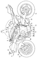
- FIG. 1 is a side view of a motorcycle equipped with a supercharger according to a first embodiment of the present invention.
- a body frame FR of the motorcycle has a main frame 1 that forms a front half portion, and a seat rail 2 that is attached to the rear portion of the main frame 1 and forms the rear half portion of the body frame FR.
- a front fork 8 is rotatably supported on a head pipe 4 provided at the front end of the main frame 1 via a steering shaft (not shown), and a front wheel 10 is attached to the front fork 8.
- a steering handle 6 is fixed to the upper end of the front fork 8.
- a swing arm 12 is pivotally supported by a rear end portion of the main frame 1 at the center lower portion of the vehicle body frame FR via a pivot shaft 16 so that the swing arm 12 can swing up and down. Is supported rotatably.
- An engine E is attached to the lower part of the main frame 1. The rotation of the engine E is transmitted to the transmission mechanism 11 such as a chain disposed on the left side of the vehicle body via the transmission 13, and the rear wheel 14 is driven via the transmission mechanism 11.
- the fuel tank 15 is arranged on the upper part of the main frame 1, and the driver's seat 18 and the passenger seat 20 are supported on the rear frame 2.
- a resin front cowl 22 that covers the front of the head pipe 4 is attached to the front of the vehicle body.
- the front cowl 22 is formed with an intake air intake 24 for taking in the intake air I to the engine E from the outside.
- Engine E is a 4-cylinder 4-cycle parallel multi-cylinder engine having a crankshaft 26 that is an engine rotation shaft extending in the vehicle width direction.
- the form of the engine E is not limited to this.
- the engine E includes a crankcase 28 that supports the crankshaft 26, a cylinder block 30 that is coupled to the top of the crankcase 28, a cylinder head 32 that is coupled to the top, and a head cover that is attached to the top of the cylinder head 32. 32a and an oil pan 34 attached to the lower part of the crankcase 28.
- the rear part of the crankcase 28 constitutes a transmission case that houses the transmission 13.
- the transmission cover 130 is detachably attached to the right side surface of the crankcase 28 by a plurality of bolts 132, and the transmission 13 can be removed by removing the transmission cover 130. ing.
- the cylinder block 30 and the cylinder head 32 in FIG. 1 are slightly inclined forward. More specifically, the piston axis of the engine E extends upward and inclined forward.
- An intake port 47 is provided at the rear of the cylinder head 32.
- Four exhaust pipes 36 connected to the exhaust port on the front surface of the cylinder head 32 are gathered below the engine E and connected to an exhaust muffler 38 disposed on the right side of the rear wheel 14.
- a supercharger 42 that takes in outside air and supplies it to the engine E as intake air I is disposed behind the cylinder block 30 and above the rear portion of the crankcase 28. That is, the supercharger 42 is located above the transmission 13.
- the supercharger 42 compresses the outside air sucked from the suction port 46, increases its pressure, discharges it from the discharge port 48, and supplies it to the engine E. Thereby, the amount of intake air supplied to the engine E can be increased.
- the suction port 46 of the supercharger 42 opens leftward above the rear portion of the crankcase 28, and the discharge port 48 opens upward near the center position in the vehicle width direction of the engine E.
- the supercharger 42 includes a supercharger rotating shaft 44 extending in the vehicle width direction, an impeller 50 that is a supercharging rotating body fixed to the supercharger rotating shaft 44, and an impeller 50. It includes an impeller housing 52 for covering, a transmission mechanism 54 for transmitting the power of the engine E to the impeller 50, and a casing 56 for covering most of the supercharger rotating shaft 44 and the transmission mechanism 54 from the radial direction.
- a speed increaser 54 formed of a planetary gear device described later is used as the transmission mechanism 54.
- the casing 56 is fixed to the upper surface of the crankcase 28 of the engine E by bolts (not shown).
- an opening OP is formed on the upper surface of the crankcase 28, and the casing 56 is fixed so as to cover the opening OP of the crankcase 28 from above.
- a later-described chain 94 (FIG. 3) that transmits power to the supercharger rotating shaft 44 passes through the opening OP.
- the speed increaser 54 and the air cleaner 40 are arranged in the vehicle width direction with the impeller housing 52 interposed therebetween.
- the impeller housing 52 is connected to the air cleaner 40 by a bolt (not shown).
- a cleaner outlet 62 of the air cleaner 40 is connected to the suction port 46 of the supercharger 42, and an intake duct 70 that introduces the traveling air A flowing in front of the cylinder block 30 to the turbocharger 42 is connected to the cleaner inlet 60 on the outer side in the vehicle width direction. Connected from.
- the cleaner inlet 60 and the outlet 70 b of the intake duct 70 are connected by connecting a plurality of bolts 55 to connecting flanges 63 and 65 provided on the outer periphery of each.
- a cleaner element 41 for purifying the intake air I is built in the connecting flanges 63 and 65.
- An intake chamber 74 is disposed between the discharge port 48 of the supercharger 42 and the intake port 47 of the engine E in FIG.
- the intake chamber 74 stores intake air I supplied from the supercharger 42 to the intake port 47.
- the intake chamber 74 is disposed above the supercharger 42, and most of the intake chamber 74 is located behind the cylinder block 30.
- the discharge port 48 of the supercharger 42 is connected to the central portion of the intake chamber 74 in the vehicle width direction. As a result, the intake air I from the supercharger 42 flows evenly into the plurality of intake ports 47 through the intake chamber 74.
- a throttle body 76 is disposed between the intake chamber 74 and the cylinder head 32.
- fuel is injected into the intake air to generate an air-fuel mixture, and this air-fuel mixture is supplied into the cylinder.
- the fuel tank 15 is disposed above the intake chamber 74 and the throttle body 76.
- the intake duct 70 is supported by the main frame 1 in such a manner that the front end opening 70a faces the intake intake 24 of the front cowl 22, and the traveling air A introduced from the opening 70a is boosted by the ram effect to be used as intake I. Introduced into the supercharger 42.
- the intake duct 70 is disposed on the left side of the vehicle body, and passes outside the cylinder block 30 and the cylinder head 32 of the engine E from below the front end of the handle 6 in a side view.
- a clutch gear 72 is provided at the right end, which is one side in the vehicle width direction of the crankshaft 26 of the engine E, and the supercharger that drives the supercharger 42 to the left of the clutch gear 72.
- a machine gear 80 is provided.
- a driven-side supercharger gear 84 that meshes with the supercharger gear 80 of the crankshaft 26 is spline-fitted so as to rotate integrally with the supercharger drive shaft 78.
- a starter gear 86 is supported on the supercharger drive shaft 78 so as to be relatively rotatable, and a starter one-way clutch 85 is interposed between the driven supercharger gear 84 and the starter gear 86.
- a starter motor 90 is connected to the starter gear 86 via a torque limiter 88.
- the starter one-way clutch 85 is connected and the starting torque is transmitted to the crankshaft 26. Further, when the rotational speed of the crankshaft 26 becomes faster than the starter motor 90 after the engine E is started, the starter one-way clutch 85 is disengaged and power transmission from the crankshaft 26 to the starter motor 90 is blocked.
- a first sprocket 92 is provided at the right end of the supercharger drive shaft 78. That is, the first sprocket 92 is provided on the right side (shaft end side) of the bearing 79 that supports the supercharger drive shaft 78.
- a chain 94 which is an endless power transmission member that transmits the power of the engine E to the supercharger 42, is stretched around the gear 92 a of the first sprocket 92.
- the chain 94 is disposed on the right side that is the opposite side of the suction port 46 of the supercharger 42 and the transmission mechanism 11 for driving the wheel in the vehicle width direction.
- the chain 94 is pressed by a tensioner 134 (FIG. 5) to apply tension. Thereby, adjustment between axes is unnecessary.
- Rotational force of the crankshaft 26 is transmitted from the supercharger drive shaft 78 to the input shaft 65 connected to the supercharger rotation shaft 44 via the chain 94.
- a second sprocket 96 is provided at the right end of the input shaft 65, and a chain 94 is stretched around a gear 96 a of the second sprocket 96.
- the input shaft 65 is a rotating shaft of the speed increaser 54.
- the supercharger rotating shaft 44 and the input shaft 65 constitute a rotating shaft body RS in which an impeller 50 is provided at one end and a second sprocket 96 which is a rotating body that transmits power from the engine E is provided at the other end. is doing.
- the supercharger rotating shaft 44 and the input shaft 65 have a common axis C that matches the vehicle width direction.
- the second sprocket 96 constitutes a rotation transmission part that is a part of a transmission rotating body RM that transmits the power from the engine E to the rotating shaft body RS.
- the input shaft 65 is a hollow shaft and is rotatably supported by the casing 56 via a bearing 98.
- Spline teeth are formed on the outer peripheral surface of the right end portion 65b of the input shaft 65, and the second sprocket 96 is connected to the input shaft 65 via a gearbox one-way clutch 100 that is spline-fitted to the outer peripheral surface.
- the second sprocket 96 and the chain 94 are arranged on the right side, which is outside the vehicle body, with respect to the supported portion 65c supported by the bearing 98 in the input shaft 65.
- the speed increaser one-way clutch 100 is disposed outside the chain 94. In the present embodiment, the speed increaser one-way clutch 100 also constitutes a part of the transmission rotating body RM.
- the speed increaser one-way clutch 100 is provided between the second sprocket 96 and the supercharger rotating shaft 44 and suppresses rotational fluctuations of power.
- the step-up gear one-way clutch 100 has a clutch structure that releases the connection between the upstream side and the downstream side when the rotational speed on the downstream side exceeds the rotational speed on the upstream side. Since the speed-up gear one-way clutch 100 is disposed outside the chain 94, the design can be easily changed and the replacement is easy. However, the gearbox one-way clutch 100 may be disposed inside the chain 94.
- a female thread portion is formed on the inner peripheral surface of the right end portion 65 b of the input shaft 65, and the speed increaser one-way clutch 100 is moved by the head portion of the bolt 102 screwed into the female thread. It is attached to the right end portion 65b via the washer 104.
- These bolts 102 and washers 104 constitute an attachment member FM that detachably attaches the speed-up gear one-way clutch 100 that is the transmission rotator RM to the input shaft 65 that is the rotation shaft RS.
- the gearbox one-way clutch 100 includes a clutch cup 91 that forms a clutch outer ring 91 and rotates integrally with the input shaft 65, a clutch inner ring 93, and a clutch element 95 disposed between the clutch outer ring 91 and the clutch inner ring 93. And a second sprocket 96 is formed on the clutch inner ring 93.
- the second sprocket 96 is disposed on the inner side (left side in the vehicle width direction) of the axial direction AX of the rotary shaft body RS in the speed increaser one-way clutch 100.
- the outer diameter d1 of the second sprocket 96 is set smaller than the outer diameter d2 of the clutch cup 91 (d1 ⁇ d2).
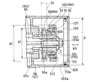
- the speed increaser one-way clutch 100, the second sprocket 96, and the bolt 102 are stored in a rotating body storage space 105 formed at the right end of the casing 56. That is, the casing 56 constitutes a supercharger case SC that houses the rotary shaft RS, the transmission rotator RM, and the attachment member FM. An opening 105 facing the outside of the vehicle body is formed at the right end of the casing 56, and the opening 105 is closed by a cap 107.
- the supercharger case SC may be formed so that it can be divided into a part that accommodates the transmission rotator RM and the attachment member FM and a part that accommodates the rotary shaft RS. Thereby, the opening 105 can be formed large, and a complicated case shape can be obtained.
- the opening 105 is an opening for accessing the transmission rotator RM and the attachment member FM from the axial direction AX of the rotary shaft RS, and the inner diameter D thereof is increased from that of the second sprocket 96 which is the transmission rotator RM.
- the speed machine one-way clutch 100 and the bolts 102 and washers 104 that are the attachment members FM are formed so as to pass therethrough (D> d2).
- FIG. 5 which is a side view of the engine viewed from the right side, the cap 107 is attached to the casing (supercharger case) 56 by a fastening member 113 such as a bolt from the vehicle width direction. That is, the cap 107 is fastened to the casing 56 by a fastening force along the axial direction AX of the rotary shaft RS.
- the fitting portion 4 is formed with a cylindrical fitting portion 111 that protrudes inward and fits into the opening 105.
- An annular seal member 109 is interposed between the inner peripheral surface 105 a of the opening 105 and the outer peripheral surface 111 a of the fitting portion 111.
- the engaging part 115 which consists of the through-hole which faced the axial center direction AX of rotating shaft RS is provided in the end surface of the clutch cup 91. As shown in FIG. The engaging portion 115 is provided so that the clutch cup 91 can be easily pulled out of the axial direction AX by engaging with a pulling tool inserted from the opening 105.
- the impeller 50 is fixed to the left end portion 44a of the supercharger rotating shaft 44 of the supercharger 42 in FIG. 3, and the left end portion 65a of the input shaft 65 is connected to the planetary gear device 106 that is the speed increaser 54.
- the left side 44b of the supercharger rotating shaft 44 is connected.
- the supercharger rotating shaft 44 is rotatably supported by the casing 56 via a bearing 99.
- the casing 56 includes an input shaft case portion 56R that supports the input shaft 65 and a rotation shaft case portion 56L that supports the supercharger rotation shaft 44.
- the input shaft case portion 56R and the rotation shaft case portion 56L are It is connected using a casing fastening member 108 such as a bolt.
- the impeller housing 52 is connected to the casing 56 using a housing fastening member 110 such as a bolt.
- the impeller housing 52 is formed with the suction port 46 opened on the left side and the discharge port 48 opened upward.
- the planetary gear unit 106 is disposed between the input shaft 65 and the supercharger rotating shaft 44 and supported by the casing 56.
- External teeth 112 are formed on the right end 44 b of the supercharger rotating shaft 44, and a plurality of planetary gears 114 are geared to the external teeth 112 side by side in the circumferential direction. That is, the external teeth 112 of the supercharger rotating shaft 44 function as the sun gear of the planetary gear device 106.
- the planetary gear 114 is gear-connected to a large-diameter internal gear (ring gear) 116 on the radially outer side.
- the planetary gear 114 is rotatably supported on the carrier shaft 122 by a bearing 120 attached to the casing 56.
- the carrier shaft 122 has a fixing member 118, and this fixing member 118 is fixed to the casing 56 with a bolt 124. That is, the carrier shaft 122 is fixed.
- An input gear 126 provided at the left end of the input shaft 65 is gear-coupled to the internal gear 116.
- the internal gear 116 is gear-connected so as to rotate in the same rotational direction as the input shaft 65, the carrier shaft 122 is fixed, and the planetary gear 114 rotates in the same rotational direction as the internal gear 116.
- the sun gear (external gear 112) is formed on the supercharger rotating shaft 44 serving as an output shaft, and rotates in the direction opposite to the planetary gear 114. That is, the planetary gear device 106 accelerates the rotation of the input shaft 65 and transmits it to the supercharger rotating shaft 44 in the rotation direction opposite to the input shaft 65.
- the supercharger drive shaft 78 rotates in conjunction with the crankshaft 26 by meshing between the supercharger gear 80 and the driven supercharger gear 84.
- the input shaft 65 rotates through the chain 94, and further, the supercharger rotary shaft 44 rotates through the planetary gear unit 106, and the supercharger 42 starts.
- the traveling wind A shown in FIG. 1 enters the intake duct 70 through the intake intake 24 and is compressed by dynamic pressure (ram pressure), passes through the intake duct 70, enters the air cleaner 40, and passes through the air cleaner 40. After being cleaned, it is introduced into the supercharger 42.
- the intake air I introduced into the supercharger 42 is pressurized by the supercharger 42 and introduced into the engine E through the intake chamber 74 and the throttle body 76. Due to the synergistic effect of the ram pressure and the pressurization by the supercharger 42, high-pressure intake air can be supplied to the engine E.
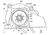
- FIG. 5 is a side view of the supercharger 42 with the cap 107 removed, as viewed from the right side.
- the bolt 102 is loosened, the bolt 102 and the washer 104 are removed from the input shaft 65 and taken out from the opening 105.
- the extraction tool T is engaged with the engaging portion (through hole) 115 of the speed increaser one-way clutch 100, and the transmission rotator RM including the second sprocket 96 and the speed increaser one-way clutch 100 is removed from the input shaft 65. Remove and remove from opening 105.
- the chain 94 When replacing the chain 94, the chain 94 can be removed from the second sprocket 96 by releasing the tension by the tensioner 134 (FIG. 5). In this way, the chain 94 that is likely to be loaded can be easily replaced. Further, since the second sprocket 96 can be attached and detached, sprockets having different diameters can be attached. Further, the first sprocket 92 can be easily replaced by loosening the bolt 132 of FIG. 5 and removing the mission cover 130. Thereby, the speed increasing ratio can be changed.
- the tool T is inserted from the opening 105 and the bolt 102 is operated to attach and detach the second sprocket 96 and the one-way clutch 100 from the input shaft 65. be able to. Thereby, workability
- the casing 56 fixed to the crankcase 28 and the input shaft 65 supported by the casing 56, the second sprocket 96, the gearbox one-way clutch 100, and the input shaft 65 can be attached and detached. Therefore, workability is further improved.
- the opening 105 is closed by a cap 107 that is detachable from the casing 56 shown in FIG. 4, it is possible to prevent foreign matter from entering through the opening 105.
- a seal member 109 is interposed between the inner peripheral surface 105a of the opening 105 and the outer peripheral surface 111a of the fitting portion 111 of the cap 107, and the cap 107 is fastened to the casing 56 by a fastening force along the axial direction AX. Therefore, a large fastening force for press-contacting the seal member 109 becomes unnecessary, and the number of fastening members can be reduced.
- the opening 105 is formed in a size that allows the second sprocket 96, the speed increaser one-way clutch 100, the bolt 102, and the washer 104 to pass through, the second sprocket 96, the speed increaser one-way clutch 100, the bolt 102, Since the washer 104 can be taken in and out from the opening 105, workability is further improved.
- the second sprocket 96 is formed in the clutch inner ring 93 of the speed increaser one-way clutch 100, it is not necessary to provide a separate sprocket wheel, and the structure is simplified.
- FIG. 7 shows a turbocharger 42 according to another example of the present invention.
- the inner diameter D of the opening 105 is set smaller than the outer diameter d1 of the second sprocket 96 and the outer diameter d2 of the clutch cup 91 (D ⁇ d1, D ⁇ d2), and the outer diameter d3 of the washer 104. (D3 ⁇ D).
- the axial clearance W1 between the input shaft 65 and the casing 56 is set to be larger than the width (axial dimension) W2 of the chain 94 (W2 ⁇ W1).
- a male screw 136 is formed on the outer periphery of the cap 107
- a female screw 138 is formed on the inner peripheral surface of the right end of the casing 56
- the cap 107 is screwed to the right end of the casing 56.
- a groove or a protrusion for angularly displacing the cap 107 around the axis is formed on the right end surface 107a of the cap 107.
- a groove (not shown) is formed in the right end surface 107 a of the cap 107, and the tool 107 is fitted in the groove (not shown) and rotated around the axis, thereby allowing the cap 107 to move relative to the casing 56. It can be removed.
- an abutting portion 140 with which the left end surface 107b of the cap 107 abuts is formed at the right end portion of the casing 56.
- the contact portion 140 is formed on the left side of the female screw 138, and an opening 105 is formed on the inner peripheral surface of the contact portion 140.
- the present invention is not limited to the above embodiment, and various additions, changes, or deletions are possible without departing from the gist of the present invention.
- the chain 94 is used as the power transmission member in the above embodiment, a belt or a gear train may be used.
- the sprocket 96 and the gearbox one-way clutch 100 are used as a rotary body, a pulley and a gear may be sufficient and a one-way clutch is not necessary.
- the supercharger 42 may be other types such as a root type, a re-sholm type, a scroll type, in addition to a centrifugal type provided with the impeller 50 as a supercharging rotator. Therefore, such a thing is also included in the scope of the present invention.
Landscapes
- Engineering & Computer Science (AREA)
- Mechanical Engineering (AREA)
- General Engineering & Computer Science (AREA)
- Chemical & Material Sciences (AREA)
- Combustion & Propulsion (AREA)
- Supercharger (AREA)
- Lubrication Of Internal Combustion Engines (AREA)
- General Details Of Gearings (AREA)
- Cylinder Crankcases Of Internal Combustion Engines (AREA)
Abstract
過給機(42)の過給機回転軸(44)における左側端部(44a)に、エンジン(E)の吸気(I)を加圧するインペラ(50)が設けられている。エンジン(E)からの動力が、チェーン(94)を介して、増速機(54)の入力軸(65)の右側端部(65b)に設けられた第2スプロケット(96)に伝達され、過給機(42)が駆動する。第2スプロケット(96)は、ボルト(102)により入力軸(65)に着脱自在に取り付けられている。これら過給機回転軸(44)、入力軸(65)、第2スプロケット(96)およびボルト(102)は、過給機ケース(56)に収納されている。過給機ケース(56)の右側端面に、軸心方向から第2スプロケット(96)およびボルト(102)にアクセスする開口(105)が形成されている。
Description
この出願は、2012年7月11日出願の特願2012-155463の優先権を主張するものであり、その全体を参照により本願の一部をなすものとして引用する。
本発明は、例えば、自動二輪車のような車両のエンジンに連結される過給機に関するものである。
自動二輪車のような車両に搭載されるエンジンにおいて、外気を加圧してエンジンに供給する過給機を設けたものがある(例えば、特許文献1)。この過給機は、エンジン回転軸に機械的にチェーンで連動してエンジン動力により駆動されるようになっている。
しかしながら、上記のような過給機では、チェーンの修理、交換をする際、作業性が悪い。
本発明は、前記課題に鑑みてなされたもので、作業性を向上できる過給機を提供することを目的とする。
上記目的を達成するために、本発明の過給機は、エンジンの動力によって駆動され、エンジンの吸気を加圧する過給機であって、過給用回転体が設けられた回転軸体と、前記回転軸体に設けられて前記回転軸体に前記動力を伝達する伝達用回転体と、前記回転軸体、前記伝達用回転体を収納する過給機ケースとを備え、前記回転軸体の軸心方向から前記伝達用回転体にアクセス可能な開口が形成されている。
ここで、伝達用回転体は、例えば、スプロケット、プーリ、ギヤであり、伝達用回転体と回転軸体との間にワンウェイクラッチを含んでもよい。回転軸体は、インペラが設けられた過給機回転軸に加え、過給機回転軸と伝達用回転体との間に増速機が介在される場合、増速機の回転軸も含む。
この構成によれば、過給機ケースを取り付けた状態で、開口から伝達用回転体の回転軸体に対する取り付け、取り外し作業を行うことができ、作業性が向上する。チェーンやベルトのような無端帯状伝達部材を介して動力が伝達用回転体に伝達される場合、伝達用回転体を回転軸体から取り外すことで、過給機ケースを取り付けた状態で、無端帯状伝達部材も交換できる。
本発明において、前記過給機ケースは、エンジンのクランクケースに固定され、前記回転軸体は前記過給機ケースに回転自在に支持されていることが好ましい。この構成によれば、過給機ケースをエンジンに固定し、回転軸体を過給機ケースに支持させた状態で、回転体と回転軸体との取り付け、取り外し作業を行うことができるから、作業性が一層向上する。
本発明において、前記開口は、前記過給機ケースに着脱自在なキャップにより閉止されていることが好ましい。この構成によれば、開口から異物が浸入するのを防ぐことができる。
本発明において、前記開口の内周面と、前記キャップにおける開口に嵌合される嵌合部の外周面との間に環状のシール部材が介装され、前記キャップが、前記回転軸体の軸心方向に沿った締結力によって、前記過給機ケースに締結されていることが好ましい。この構成によれば、シール部材を圧接させる大きな締結力が不要になり、締結部材の数を減らせる。
本発明において、前記伝達用回転体を前記回転軸体に着脱自在に取り付ける取付部材が前記開口を通過できる大きさに形成すれば、取付部材を開口から出し入れできるので、作業性が一層向上する。また、前記開口を前記伝達用回転体が通過できる大きさに形成すれば、回転体を開口から出し入れできるので、作業性がさらに向上する。
前記回転体がワンウェイクラッチを含む場合、前記ワンウェイクラッチは、前記回転軸体と一体回転するクラッチ外輪と、クラッチ内輪と、前記クラッチ外輪と前記クラッチ内輪との間に配置されたクラッチ素子とを有し、前記クラッチ内輪に、前記回転軸体に前起動力を伝達する回転伝達部が形成されていることが好ましい。この構成によれば、別途回転伝達部を設けることが不要になり、構造が簡単になる。
請求の範囲および/または明細書および/または図面に開示された少なくとも2つの構成のどのような組合せも、本発明に含まれる。特に、請求の範囲の各請求項の2つ以上のどのような組合せも、本発明に含まれる。
本発明は、添付の図面を参考にした以下の好適な実施形態の説明からより明瞭に理解されるであろう。しかしながら、実施形態および図面は単なる図示および説明のためのものであり、本発明の範囲を定めるために利用されるべきものではない。本発明の範囲は添付の請求の範囲によって定まる。添付図面において、複数の図面における同一の部品番号は、同一または相当部分を示す。
本発明の第1実施形態に係る過給機を搭載した自動二輪車を示す側面図である。
同自動二輪車のエンジンの要部を後方斜め上方から見た斜視図である。
同過給機の駆動系を示す軸配置図である。
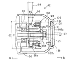
図3の要部拡大図である。
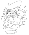
同エンジンを示す側面図である。
同過給機のキャップを外した状態を示す側面図である。
同過給機の別の例を示す拡大断面図である。
以下、本発明の好ましい実施形態について図面を参照しながら説明する。本明細書において、「左側」および「右側」は、車両に乗車した運転者から見た左右側をいう。
図1は本発明の第1実施形態に係る過給機を搭載した自動二輪車の側面図である。この自動二輪車の車体フレームFRは、前半部を形成するメインフレーム1と、このメインフレーム1の後部に取り付けられて車体フレームFRの後半部を形成するシートレール2とを有している。メインフレーム1の前端に設けられたヘッドパイプ4に、図示しないステアリングシャフトを介してフロントフォーク8が回動自在に軸支されて、このフロントフォーク8に前輪10が取り付けられている。フロントフォーク8の上端部に操向用のハンドル6が固定されている。
一方、車体フレームFRの中央下部であるメインフレーム1の後端部に、ピボット軸16を介してスイングアーム12が上下揺動自在に軸支され、このスイングアーム12の後端部に後輪14が回転自在に支持されている。メインフレーム1の下部にエンジンEが取り付けられている。エンジンEの回転がトランスミッション13を介して、車体左側に配置されたチェーンのような伝達機構11に伝達され、この伝達機構11を介して後輪14が駆動される。
メインフレーム1の上部に燃料タンク15が配置され、リヤフレーム2に操縦者用シート18および同乗車用シート20が支持されている。また、車体前部に、前記ヘッドパイプ4の前方を覆う樹脂製のフロントカウル22が装着されている。フロントカウル22には、外部からエンジンEへの吸気Iを取り入れる吸気取入口24が形成されている。
エンジンEは、車幅方向に延びるエンジン回転軸であるクランク軸26を有する4気筒4サイクルの並列多気筒エンジンである。エンジンEの形式はこれに限定されない。エンジンEは、クランク軸26を支持するクランクケース28と、クランクケース28の上部に連結されたシリンダブロック30と、その上部に連結されたシリンダヘッド32と、シリンダヘッド32の上部に取り付けられたヘッドカバー32aと、クランクケース28の下部に取り付けられたオイルパン34とを有している。クランクケース28の後部は、トランスミッション13を収納するミッションケースを構成している。
図5に示すように、クランクケース28の右側面に、複数のボルト132によりミッションカバー130が着脱自在に取り付けられており、このミッションカバー130を取り外すことで、トランスミッション13の取り外しができるようになっている。
図1のシリンダブロック30およびシリンダヘッド32は若干前傾している。具体的には、エンジンEのピストン軸線が上方に向かって前方に傾斜して延びている。シリンダヘッド32の後部に吸気ポート47が設けられている。シリンダヘッド32の前面の排気ポートに接続された4本の排気管36が、エンジンEの下方で集合され、後輪14の右側に配置された排気マフラ38に接続されている。シリンダブロック30の後方でクランクケース28の後部の上方に、外気を取り込んで吸気IとしてエンジンEに供給する過給機42が配置されている。すなわち、過給機42は、トランスミッション13の上方に位置している。
過給機42は、吸込口46から吸引した外気を圧縮して、その圧力を高めたのち吐出口48から吐出して、エンジンEに供給する。これにより、エンジンEに供給する吸気量を増大させることができる。過給機42の吸込口46は、クランクケース28の後部の上方に左向きに開口しており、吐出口48はエンジンEの車幅方向中央位置付近に上方を向いて開口している。
図2に示すように、過給機42は、車幅方向に延びる過給機回転軸44と、過給機回転軸44に固定された過給用回転体であるインペラ50と、インペラ50を覆うインペラハウジング52と、エンジンEの動力をインペラ50に伝達する伝達機構54と、過給機回転軸44の大部分と伝達機構54を径方向から覆うケーシング56とを有している。本実施形態では、伝達機構54として、後述の遊星歯車装置からなる増速機54が用いられている。ケーシング56は、ボルト(図示せず)によりエンジンEのクランクケース28の上面に固定されている。
詳細には、クランクケース28の上面に開口OPが形成され、ケーシング56は、クランクケース28の開口OPを上方から覆うように固定される。過給機回転軸44へ動力を伝達する後述のチェーン94(図3)は、開口OPを通過する。
インペラハウジング52を挟んで車幅方向に増速機54とエアクリーナ40とが配置されている。インペラハウジング52は、図示しないボルトによりエアクリーナ40と連結されている。
過給機42の吸込口46にエアクリーナ40のクリーナ出口62が接続され、クリーナ入口60に、シリンダブロック30の前方を流れる走行風Aを過給機42に導入する吸気ダクト70が車幅方向外側から接続されている。クリーナ入口60と吸気ダクト70の導出口70bとは、それぞれの外周に設けられた連結用フランジ63,65を複数のボルト55で連結することにより接続されている。これら連結用フランジ63,65に、吸気Iを浄化するクリーナエレメント41が内蔵されている。
過給機42の吐出口48と図1のエンジンEの吸気ポート47との間に吸気チャンバ74が配置されている。吸気チャンバ74は、過給機42から吸気ポート47に供給される吸気Iを溜める。吸気チャンバ74は、過給機42の上方に配置され、その大部分がシリンダブロック30の後方に位置している。図2に示すように、過給機42の吐出口48は、吸気チャンバ74の車幅方向中央部に接続されている。これにより、過給機42からの吸気Iが吸気チャンバ74を経て複数の吸気ポート47に均等に流入する。
図1に示すように、吸気チャンバ74とシリンダヘッド32との間には、スロットルボディ76が配置されている。このスロットルボディ76において、吸入空気中に燃料が噴射されて混合気が生成され、この混合気がシリンダ内に供給される。これら吸気チャンバ74およびスロットルボディ76の上方に、前記燃料タンク15が配置されている。
吸気ダクト70は、前端開口70aをフロントカウル22の吸気取入口24に臨ませた配置でメインフレーム1に支持されており、開口70aから導入した走行風Aをラム効果により昇圧させ、吸気Iとして過給機42に導入する。吸気ダクト70は、車体の左側に配置され、側面視で、ハンドル6の先端部の下方からエンジンEのシリンダブロック30およびシリンダヘッド32の外側を通過する。
図3に示すように、エンジンEのクランク軸26の車幅方向一方側である右側の端部にクラッチギヤ72が設けられ、このクラッチギヤ72よりも左側に過給機42を駆動する過給機用ギヤ80が設けられている。クランク軸26の過給機用ギヤ80に噛み合う従動側過給機用ギヤ84が過給機駆動軸78に一体回転するようにスプライン嵌合されている。スタータギヤ86が過給機駆動軸78に相対回転自在に支持され、従動側過給機用ギヤ84とスタータギヤ86との間にスタータワンウェイクラッチ85が介在されている。スタータギヤ86に、トルクリミッタ88を介してスタータモーター90が接続されている。
これにより、エンジンEが停止している状態でスタータモーター90が回転するとスタータワンウェイクラッチ85が接続されて、クランク軸26へ始動トルクが伝達される。また、エンジンEの始動後にクランク軸26の回転速度がスタータモーター90より速くなると、スタータワンウェイクラッチ85が遮断されてクランク軸26からスタータモーター90への動力伝達が阻止される。
過給機駆動軸78の右側端部に、第1スプロケット92が設けられている。つまり、第1スプロケット92は、過給機駆動軸78を支持する軸受79よりも右側(軸端側)に設けられている。この第1スプロケット92の歯車92aに、エンジンEの動力を過給機42に伝達する無端動力伝達部材であるチェーン94が掛け渡されている。チェーン94は、過給機42の吸込口46および車輪駆動用の伝達機構11の車幅方向反対側である右側に配置されている。チェーン94はテンショナ134(図5)によって押し付けられることで、テンションが加えられている。これにより、軸間調整が不要である。
クランク軸26の回転力が、過給機駆動軸78からチェーン94を介して、過給機回転軸44に連結された入力軸65に伝達されている。詳細には、入力軸65の右側端部に、第2スプロケット96が設けられ、この第2スプロケット96の歯車96aにチェーン94が掛け渡されている。入力軸65は、増速機54の回転軸である。
これら過給機回転軸44および入力軸65が、一端にインペラ50が設けられて他端にエンジンEからの動力を伝達する回転体である第2スプロケット96が設けられた回転軸体RSを構成している。過給機回転軸44と入力軸65は車幅方向に合致した共通の軸心Cを有しており、増速機54を設けない場合、過給機回転軸44と入力軸65は単一の軸体によって形成される。また、第2スプロケット96は、エンジンEからの動力を回転軸体RSに伝達する伝達用回転体RMの一部である回転伝達部を構成している。
入力軸65は中空軸からなり、軸受98を介してケーシング56に回転自在に支持されている。入力軸65における右側端部65bの外周面にスプライン歯が形成され、この外周面にスプライン嵌合された増速機ワンウェイクラッチ100を介して、前記第2スプロケット96が入力軸65に連結されている。つまり、第2スプロケット96およびチェーン94は、入力軸65における軸受98で支持された被支持部65cよりも車体外側である右側に配置されている。増速機ワンウェイクラッチ100は、チェーン94の外側に配置されている。本実施形態では、増速機ワンウェイクラッチ100も伝達用回転体RMの一部を構成している。
増速機ワンウェイクラッチ100は、第2スプロケット96と過給機回転軸44との間に設けられ、動力の回転変動を抑制する。増速機ワンウェイクラッチ100は、下流側の回転速度が上流側の回転速度を超えると上流側と下流側との連結を解除するクラッチ構造を有している。増速機ワンウェイクラッチ100は、チェーン94の外側に配置されているので、設計変更がし易いうえに、交換も容易である。ただし、増速機ワンウェイクラッチ100をチェーン94の内側に配置してもよい。
図4に示すように、入力軸65の右側端部65bの内周面に雌ねじ部が形成されており、増速機ワンウェイクラッチ100が、この雌ねじに螺合されたボルト102の頭部により、ワッシャ104を介して、右側端部65bに装着されている。これらボルト102およびワッシャ104が、伝達用回転体RMである増速機ワンウェイクラッチ100を回転軸体RSである入力軸65に着脱自在に取り付ける取付部材FMを構成する。
増速機ワンウェイクラッチ100は、クラッチ外輪91を形成し入力軸65と一体回転するクラッチカップ91と、クラッチ内輪93と、クラッチ外輪91とクラッチ内輪93との間に配置されたクラッチ素子95とを有し、クラッチ内輪93に第2スプロケット96が形成されている。このように、クラッチ内輪93と第2スプロケット96が一体に形成されているので、部品点数を削減できる。第2スプロケット96は、増速機ワンウェイクラッチ100における回転軸体RSの軸心方向AXの内側(車幅方向左側)に配置されている。第2スプロケット96の外径d1は、クラッチカップ91の外径d2よりも小さく設定されている(d1<d2)。
これら増速機ワンウェイクラッチ100、第2スプロケット96およびボルト102は、ケーシング56の右側端部に形成された回転体収納空間105に収納されている。つまり、ケーシング56は、回転軸体RS、伝達用回転体RMおよび取付部材FMを収納する過給機ケースSCを構成する。ケーシング56の右側端には、車体外側を向いた開口105が形成され、この開口105がキャップ107により塞がれている。過給機ケースSCは、伝達用回転体RMおよび取付部材FMを収納する部分と、回転軸体RSを収納する部分とで分割可能に形成されてもよい。これにより、開口105を大きく形成することができるとともに、複雑なケース形状とすることができる。
開口105は、回転軸体RSの軸心方向AXから伝達用回転体RMおよび取付部材FMにアクセスするための開口であり、その内径Dは、伝達用回転体RMである第2スプロケット96と増速機ワンウェイクラッチ100、および取付部材FMであるボルト102、ワッシャ104が通過できる大きさに形成されている(D>d2)。エンジンを右側から見た側面図である図5に示すように、キャップ107は、車幅方向からボルトのような締結部材113によってケーシング(過給機ケース)56に取り付けられている。つまり、キャップ107は、回転軸体RSの軸心方向AXに沿った締結力によって、ケーシング56に締結されている。
図4のキャップ107の内面に、内側に突出して開口105に嵌合する筒状の嵌合部111が形成されている。開口105の内周面105aと、嵌合部111の外周面111aとの間に環状のシール部材109が介装されている。
クラッチカップ91の端面に、回転軸体RSの軸心方向AXを向いた貫通孔からなる係合部115が設けられている。係合部115は、開口105から挿入される抜出し工具に係合してクラッチカップ91を軸心方向AXの外側に容易に抜き出すことができるように設けられている。
図3の過給機42の過給機回転軸44の左側端部44aに前記インペラ50が固定され、入力軸65の左側端部65aに、増速機54である遊星歯車装置106を介して過給機回転軸44の左側部44bが連結されている。
過給機回転軸44は、軸受99を介してケーシング56に回転自在に支持されている。ケーシング56は、入力軸65を支持する入力軸ケース部56Rと、過給機回転軸44を支持する回転軸ケース部56Lとからなり、これら入力軸ケース部56Rと回転軸ケース部56Lとが、ボルトのようなケーシング締結部材108を用いて連結されている。さらに、インペラハウジング52が、ボルトのようなハウジング締結部材110を用いてケーシング56に連結されている。インペラハウジング52には、左側に開口した前記吸込口46と上方に開口した前記吐出口48とが形成されている。
上述のように、遊星歯車装置106は入力軸65と過給機回転軸44との間に配置され、ケーシング56に支持されている。過給機回転軸44の右側端部44bに、外歯112が形成されており、この外歯112に複数の遊星歯車114が周方向に並んでギヤ連結されている。すなわち、過給機回転軸44の外歯112は、遊星歯車装置106の太陽歯車として機能する。さらに、遊星歯車114は径方向外側で大径の内歯車(リングギヤ)116にギヤ連結している。遊星歯車114は、ケーシング56に装着された軸受120によりキャリア軸122に回転自在に支持されている。
キャリア軸122は固定部材118を有しており、この固定部材118がケーシング56にボルト124により固定されている。つまり、キャリア軸122は固定されている。内歯車116には入力軸65の左側端部に設けられた入力ギヤ126がギヤ連結されている。このように、内歯車116が入力軸65と同じ回転方向に回転するようにギヤ接続され、キャリア軸122が固定されて遊星歯車114は内歯車116と同じ回転方向に回転する。太陽歯車(外歯車112)は出力軸となる過給機回転軸44に形成されており、遊星歯車114と反対の回転方向に回転する。つまり、遊星歯車装置106は、入力軸65の回転を増速して、入力軸65と反対の回転方向で過給機回転軸44に伝達している。
図3に示すクランク軸26が回転すると、過給機駆動軸78が、過給機用ギヤ80と従動側過給機用ギヤ84との噛み合いによりクランク軸26に連動して回転する。過給機駆動軸78が回転すると、チェーン94を介して入力軸65が回転し、さらに、遊星歯車装置106を介して過給機回転軸44が回転して過給機42が始動する。
自動二輪車が走行すると、図1に示す走行風Aは、吸気取入口24から吸気ダクト70に入って動圧(ラム圧)により圧縮され、吸気ダクト70を通ってエアクリーナ40に入り、エアクリーナ40で清浄化されたのち過給機42に導入される。過給機42に導入された吸気Iは、過給機42により加圧されて、吸気チャンバ74およびスロットルボディ76を介してエンジンEへ導入される。このようなラム圧と過給機42による加圧との相乗効果により、エンジンEに高圧の吸気を供給することができる。
つぎに、第2スプロケット96、増速機ワンウェイクラッチ100、ボルト102、ワッシャ104の取り外し方法について説明する。まず、図5のボルト113を緩めて、キャップ107を取り外す。図6は、キャップ107を取り外した状態の過給機42を右側から見た側面図である。つづいて、ボルト102を緩めて、ボルト102およびワッシャ104を入力軸65から取り外して、開口105から取り出す。最後に、増速機ワンウェイクラッチ100の係合部(貫通孔)115に抜出し工具Tを係合させ、第2スプロケット96および増速機ワンウェイクラッチ100を含む伝達用回転体RMを入力軸65から取り外して、開口105から取り出す。
チェーン94を交換する場合、テンショナ134(図5)によるテンションを解除することで、第2スプロケット96からチェーン94を取り外すことができる。このように、負荷がかかりやすいチェーン94を容易に交換することができる。さらに、第2スプロケット96を着脱できるので、径の異なるスプロケットを取付けることができる。また、図5のボルト132を緩めて、ミッションカバー130を取り外すことで、第1スプロケット92も容易に交換することができる。これにより、増速比を変えることができる。
上記構成において、ケーシング56を取り付けた状態で、開口か105ら工具Tを差し込んでボルト102を操作して、第2スプロケット96および増速機ワンウェイクラッチ100の入力軸65に対する取り付け、取り外し作業を行うことができる。これにより、作業性が向上する。また、第2スプロケット96および増速機ワンウェイクラッチ100を入力軸65から取り外すことで、ケーシング56を取り付けた状態で、チェーン94も交換できる。
さらに、ケーシング56をクランクケース28に固定し、入力軸65をケーシング56に支持した状態で、第2スプロケット96および増速機ワンウェイクラッチ100と入力軸65との取り付け、取り外し作業を行うことができるから、作業性が一層向上する。
また、開口105は、図4に示すケーシング56に着脱自在なキャップ107により閉止されているので、開口105から異物が浸入するのを防ぐことができる。
さらに、開口105の内周面105aとキャップ107の嵌合部111の外周面111aとの間にシール部材109が介装され、キャップ107が軸心方向AXに沿った締結力によってケーシング56に締結されているので、シール部材109を圧接させる大きな締結力が不要になり、締結部材の数を減らすことができる。
また、開口105は、第2スプロケット96、増速機ワンウェイクラッチ100、ボルト102、ワッシャ104が通過できる大きさに形成されているので、第2スプロケット96、増速機ワンウェイクラッチ100、ボルト102、ワッシャ104を開口105から出し入れできるので、作業性がさらに向上する。
さらに、増速機ワンウェイクラッチ100のクラッチ内輪93に、第2スプロケット96が形成されているので、別途スプロケットホイールを設けるのが不要となり、構造が簡単になる。
図7は、本発明の別の例の過給機42を示す。図7の例では、開口105の内径Dは、第2スプロケット96の外径d1およびクラッチカップ91の外径d2よりも小さく設定され(D<d1,D<d2)、ワッシャ104の外径d3よりも大きく設定されている(d3<D)。さらに、入力軸65とケーシング56との軸方向隙間W1が、チェーン94の幅(軸方向寸法)W2よりも大きく設定されている(W2<W1)。これにより、開口105の内径Dが外径d1,d2よりも小さくても、開口105からチェーン94を取り外せる。具体的には、ボルト102を緩めて、第2スプロケット96をチェーン94から外れるようにずらすことで、チェーン94のテンションを緩めることができ、チェーン94のメンテナンスを行うことができる。
さらに、図7の例では、キャップ107の外周に雄ねじ136が形成され、ケーシング56の右側端の内周面に雌ねじ138が形成され、キャップ107がケーシング56の右側端に螺合されている。この場合、キャップ107の右側端面107aに、キャップ107を軸心周りに角変位させるための溝または突起を形成するのが好ましい。この例では、キャップ107の右側端面107aに溝(図示せず)が形成され、工具を溝(図示せず)にはめ込んで軸心周りに回動させることで、キャップ107をケーシング56に対して着脱できるようになっている。
また、ケーシング56の右端部に、キャップ107の左側端面107bが当接する当接部140が形成されている。当接部140は、雌ねじ138よりも左側に形成され、当接部140の内周面に開口105が形成されている。
本発明は、以上の実施形態に限定されるものでなく、本発明の要旨を逸脱しない範囲内で、種々の追加、変更または削除が可能である。例えば、上記実施形態では、動力伝達部材としてチェーン94が用いられているが、ベルト、ギヤトレインであってもよい。また、上記実施形態では、回転体としてスプロケット96および増速機ワンウェイクラッチ100が用いられているが、プーリ、ギヤであってもよく、ワンウェイクラッチはなくてもよい。さらに、過給機42は、インペラ50を過給用回転体として備える遠心式のほか、ルーツ式、リショルム式、スクロール式など他の形式であってもよい。したがって、そのようなものも本発明の範囲内に含まれる。
28 クランクケース
42 過給機
44 過給機回転軸(回転軸体RS)
44a 一端部
50 インペラ(過給用回転体)
56 ケーシング(過給機ケース)
65 入力軸(回転軸体RS)
65b 他端部
91 クラッチカップ(クラッチ外輪)
93 クラッチ内輪
94 チェーン(動力伝達部材)
95 クラッチ素子
96 第2スプロケット(伝達用回転体RM、回転伝達部)
100 増速機ワンウェイクラッチ(伝達用回転体RM)
102 ボルト(取付部材FM)
104 ワッシャ(取付部材FM)
105 開口
107 キャップ
109 シール部材
E エンジン
I 吸気
42 過給機
44 過給機回転軸(回転軸体RS)
44a 一端部
50 インペラ(過給用回転体)
56 ケーシング(過給機ケース)
65 入力軸(回転軸体RS)
65b 他端部
91 クラッチカップ(クラッチ外輪)
93 クラッチ内輪
94 チェーン(動力伝達部材)
95 クラッチ素子
96 第2スプロケット(伝達用回転体RM、回転伝達部)
100 増速機ワンウェイクラッチ(伝達用回転体RM)
102 ボルト(取付部材FM)
104 ワッシャ(取付部材FM)
105 開口
107 キャップ
109 シール部材
E エンジン
I 吸気
Claims (9)
- エンジンの動力によって駆動され、エンジンの吸気を加圧する過給機であって、
過給用回転体が設けられた回転軸体と、
前記回転軸体に設けられて前記回転軸に前記動力を伝達する伝達用回転体と、
前記回転軸体、前記伝達用回転体を収納する過給機ケースと、
を備え、
前記回転軸体の軸心方向から前記伝達用回転体にアクセス可能な開口が形成されている過給機。 - 請求項1に記載の過給機において、前記過給機ケースは、エンジンのクランクケースに固定され、回転軸体は前記過給機ケースに回転自在に支持されている過給機。
- 請求項1または2に記載の過給機において、前記開口は、前記過給機ケースに着脱自在なキャップにより閉止されている過給機。
- 請求項1から3のいずれか一項に記載の過給機において、前記開口の内周面と、前記キャップにおける開口に嵌合される嵌合部の外周面との間に環状のシール部材が介装され、
前記キャップが、前記回転軸体の軸心方向に沿った締結力によって、前記過給機ケースに締結されている過給機。 - 請求項1から4のいずれか一項に記載の過給機において、無端帯状伝達部材を介して前記動力が前記伝達用回転体に伝達される過給機。
- 請求項1から5のいずれか一項に記載の過給機において、さらに、前記回転体を前記回転軸体に着脱自在に取り付ける取付部材を備え、
前記開口は、前記取付部材が通過可能に形成されている過給機。 - 請求項1から6のいずれか一項に記載の過給機において、前記伝達用回転体は、前記回転軸体の軸受よりも軸方向で前記開口側に配置され、
前記開口は、前記伝達用回転体が通過可能に形成されている過給機。 - 請求項1から7のいずれか一項に記載の過給機において、前記伝達用回転体は、ワンウェイクラッチを含んでいる過給機。
- 請求項8に記載の過給機において、前記ワンウェイクラッチは、前記回転軸体と一体回転するクラッチ外輪と、クラッチ内輪と、前記クラッチ外輪と前記クラッチ内輪との間に配置されたクラッチ素子とを有し、
前記クラッチ内輪に、前記回転軸体に前記動力を伝達する回転伝達部が形成されている過給機。
Priority Applications (4)
| Application Number | Priority Date | Filing Date | Title |
|---|---|---|---|
| JP2014524843A JP5945325B2 (ja) | 2012-07-11 | 2013-07-10 | エンジンの過給機 |
| CN201380036346.0A CN104428513B (zh) | 2012-07-11 | 2013-07-10 | 发动机的增压器 |
| EP13816004.9A EP2878788B1 (en) | 2012-07-11 | 2013-07-10 | Engine supercharger |
| US14/591,803 US10190454B2 (en) | 2012-07-11 | 2015-01-07 | Motorcycle supercharger |
Applications Claiming Priority (2)
| Application Number | Priority Date | Filing Date | Title |
|---|---|---|---|
| JP2012-155463 | 2012-07-11 | ||
| JP2012155463 | 2012-07-11 |
Related Child Applications (1)
| Application Number | Title | Priority Date | Filing Date |
|---|---|---|---|
| US14/591,803 Continuation US10190454B2 (en) | 2012-07-11 | 2015-01-07 | Motorcycle supercharger |
Publications (1)
| Publication Number | Publication Date |
|---|---|
| WO2014010639A1 true WO2014010639A1 (ja) | 2014-01-16 |
Family
ID=49916088
Family Applications (3)
| Application Number | Title | Priority Date | Filing Date |
|---|---|---|---|
| PCT/JP2013/068915 Ceased WO2014010652A1 (ja) | 2012-07-11 | 2013-07-10 | エンジンの過給機取付構造 |
| PCT/JP2013/068900 Ceased WO2014010639A1 (ja) | 2012-07-11 | 2013-07-10 | エンジンの過給機 |
| PCT/JP2013/068916 Ceased WO2014010653A1 (ja) | 2012-07-11 | 2013-07-10 | 車両用エンジンの潤滑システム |
Family Applications Before (1)
| Application Number | Title | Priority Date | Filing Date |
|---|---|---|---|
| PCT/JP2013/068915 Ceased WO2014010652A1 (ja) | 2012-07-11 | 2013-07-10 | エンジンの過給機取付構造 |
Family Applications After (1)
| Application Number | Title | Priority Date | Filing Date |
|---|---|---|---|
| PCT/JP2013/068916 Ceased WO2014010653A1 (ja) | 2012-07-11 | 2013-07-10 | 車両用エンジンの潤滑システム |
Country Status (5)
| Country | Link |
|---|---|
| US (3) | US9869218B2 (ja) |
| EP (3) | EP2878787B1 (ja) |
| JP (3) | JP5944506B2 (ja) |
| CN (3) | CN104428510B (ja) |
| WO (3) | WO2014010652A1 (ja) |
Families Citing this family (25)
| Publication number | Priority date | Publication date | Assignee | Title |
|---|---|---|---|---|
| CN104471211B (zh) * | 2012-07-11 | 2017-04-19 | 川崎重工业株式会社 | 带增压器的发动机 |
| US9915192B2 (en) * | 2014-08-04 | 2018-03-13 | Jeffrey J. Buschur | Power conversion device |
| JP6156296B2 (ja) * | 2014-09-11 | 2017-07-05 | マツダ株式会社 | エンジンのオイル供給装置 |
| JP6142885B2 (ja) * | 2015-03-05 | 2017-06-07 | マツダ株式会社 | エンジンのオイル供給装置、エンジンの製造方法及びエンジンの給油路構造 |
| JP6601134B2 (ja) * | 2015-10-13 | 2019-11-06 | スズキ株式会社 | 4サイクル多気筒エンジン |
| JP6623680B2 (ja) * | 2015-10-27 | 2019-12-25 | スズキ株式会社 | 内燃機関の潤滑構造及び自動二輪車 |
| JP6627412B2 (ja) * | 2015-10-27 | 2020-01-08 | スズキ株式会社 | 内燃機関の潤滑構造及び自動二輪車 |
| JP6668681B2 (ja) * | 2015-10-27 | 2020-03-18 | スズキ株式会社 | 鞍乗型車両 |
| JP6551152B2 (ja) * | 2015-10-27 | 2019-07-31 | スズキ株式会社 | 内燃機関の潤滑構造及び自動二輪車 |
| US10167767B2 (en) | 2015-10-27 | 2019-01-01 | Suzuki Motor Corporation | Motorcycle and saddle-ridden type vehicle |
| US10018084B2 (en) * | 2015-10-27 | 2018-07-10 | Suzuki Motor Corporation | Lubricating structure of internal combustion engine and motorcycle |
| US10086903B2 (en) * | 2015-10-27 | 2018-10-02 | Suzuki Motor Corporation | Saddle-ridden vehicle |
| DE102016012781A1 (de) * | 2015-10-27 | 2017-04-27 | Suzuki Motor Corporation | Schmierstruktur eines Verbrennungsmotors und Motorrad |
| JP2017125432A (ja) * | 2016-01-13 | 2017-07-20 | ヤマハ発動機株式会社 | 自動二輪車 |
| US10378491B2 (en) * | 2016-03-08 | 2019-08-13 | K&N Engineering, Inc. | Aircharger air intake system and method |
| US10690045B2 (en) * | 2017-03-05 | 2020-06-23 | Southwest Research Institute | Intake air boost system for two-cycle engine having roots blowers |
| JP6437597B1 (ja) * | 2017-06-16 | 2018-12-12 | 本田技研工業株式会社 | 内燃機関 |
| US11680582B2 (en) * | 2017-09-25 | 2023-06-20 | Johnson Controls Tyco IP Holdings LLP | Two piece split scroll for centrifugal compressor |
| JP7040979B2 (ja) | 2018-03-29 | 2022-03-23 | 本田技研工業株式会社 | 内燃機関の油路構造 |
| EP3797219B1 (en) | 2018-05-23 | 2026-04-08 | Cummins, Inc. | System and method for a captive sprocket in an engine |
| JP2019214979A (ja) * | 2018-06-13 | 2019-12-19 | スズキ株式会社 | 内燃機関 |
| MY196748A (en) * | 2018-09-25 | 2023-05-03 | Honda Motor Co Ltd | Power unit for straddle-type vehicles |
| JP7287261B2 (ja) | 2019-12-18 | 2023-06-06 | トヨタ紡織株式会社 | 吸気ダクト |
| CN113309846A (zh) * | 2020-02-27 | 2021-08-27 | Tvs电机股份有限公司 | 用于机动车辆的动力装置 |
| JP2021173242A (ja) * | 2020-04-28 | 2021-11-01 | ヤマハモーターパワープロダクツ株式会社 | V型ohvエンジン |
Citations (6)
| Publication number | Priority date | Publication date | Assignee | Title |
|---|---|---|---|---|
| JPH0270920A (ja) * | 1988-09-02 | 1990-03-09 | Yamaha Motor Co Ltd | 過給機付きエンジンを備えた自動二輪車 |
| JPH08189370A (ja) * | 1994-01-25 | 1996-07-23 | Komatsu Ltd | 差動駆動過給装置およびその制御方法 |
| JPH08232757A (ja) * | 1995-02-23 | 1996-09-10 | Yamaha Motor Co Ltd | エンジン |
| JP2001233276A (ja) * | 2000-02-24 | 2001-08-28 | Yamaha Motor Co Ltd | 過給機を備えた自動二輪車 |
| JP2008190426A (ja) * | 2007-02-05 | 2008-08-21 | Yanmar Co Ltd | エンジン |
| JP2011247267A (ja) * | 2011-07-14 | 2011-12-08 | Honda Motor Co Ltd | 内燃機関 |
Family Cites Families (52)
| Publication number | Priority date | Publication date | Assignee | Title |
|---|---|---|---|---|
| FR2129208A5 (ja) * | 1971-03-12 | 1972-10-27 | Berliet Automobiles | |
| DE2843248C2 (de) * | 1978-10-04 | 1984-08-23 | Klöckner-Humboldt-Deutz AG, 5000 Köln | Schmierölkreislauf für eine Brennkraftmaschine |
| JPS5893930A (ja) * | 1981-11-27 | 1983-06-03 | Honda Motor Co Ltd | 内燃機関におけるエアポンプの駆動方法 |
| JPS6138126A (ja) * | 1984-07-31 | 1986-02-24 | Yoichi Yamazaki | タ−ボチヤ−ジヤの焼付き防止装置 |
| JP2515316B2 (ja) * | 1987-03-10 | 1996-07-10 | マツダ株式会社 | エンジンの機械式過給装置 |
| DE3832013C2 (de) * | 1987-09-17 | 1996-08-01 | Dancho Zochev Dipl Ing Donkov | Hubkolben-Brennkraftmaschine mit Kurbelgehäuse-Ladeluftpumpen |
| JPH026289A (ja) * | 1988-06-23 | 1990-01-10 | Yamaha Motor Co Ltd | 過給機付きエンジンを備えた自動二輪車 |
| JPH0224282A (ja) * | 1988-07-11 | 1990-01-26 | Yamaha Motor Co Ltd | 過給機付きエンジンを備えた自動二輪車 |
| JPH0224283A (ja) * | 1988-07-11 | 1990-01-26 | Yamaha Motor Co Ltd | 過給機付きエンジンを備えた自動二輪車 |
| JP2716763B2 (ja) * | 1988-12-14 | 1998-02-18 | ヤマハ発動機株式会社 | 自動二輪車用エンジンのバランサ軸配置構造 |
| JPH02264117A (ja) * | 1989-03-31 | 1990-10-26 | Mazda Motor Corp | 機械式過給機付エンジンの吸気装置 |
| JPH05256146A (ja) * | 1992-03-12 | 1993-10-05 | Tochigi Fuji Ind Co Ltd | 機械式過給機 |
| GB2300450A (en) | 1994-01-25 | 1996-11-06 | Komatsu Mfg Co Ltd | Differential driving supercharger and method for controlling the same |
| US6105558A (en) * | 1995-05-12 | 2000-08-22 | Bushling; William | Supercharging apparatus |
| JPH08312498A (ja) * | 1995-05-17 | 1996-11-26 | Mitsubishi Motors Corp | 自動車の潤滑装置 |
| JPH09287466A (ja) * | 1996-04-23 | 1997-11-04 | Yamaha Motor Co Ltd | 過給エンジン搭載車両 |
| US5823159A (en) * | 1997-09-26 | 1998-10-20 | Southwest Research Institute | Independent valve train lubrication system |
| JPH11257084A (ja) * | 1998-03-17 | 1999-09-21 | Yanmar Diesel Engine Co Ltd | 内燃機関における過給機の潤滑装置 |
| JP2001233277A (ja) * | 2000-02-24 | 2001-08-28 | Yamaha Motor Co Ltd | 過給機を備えた自動二輪車 |
| AU2001243304A1 (en) * | 2000-02-29 | 2001-09-12 | Bombardier Inc. | Four stroke engine having blow-by ventilation system and lubrication system |
| US7000577B2 (en) * | 2000-02-29 | 2006-02-21 | Brp-Rotax Gmbh & Co. Kg | Modular engine family |
| US7299792B1 (en) * | 2000-09-22 | 2007-11-27 | Accessible Technologies, Inc. | Centrifugal compressor with improved lubrication system for gear-type transmission |
| JP2002276383A (ja) * | 2001-03-15 | 2002-09-25 | Nissan Diesel Motor Co Ltd | ターボ過給機付きエンジンの潤滑装置 |
| JP3928035B2 (ja) * | 2001-12-27 | 2007-06-13 | 株式会社エッチ・ケー・エス | 過給機 |
| JP2004270459A (ja) * | 2003-03-05 | 2004-09-30 | Komatsu Ltd | ターボチャージャ付きエンジンの潤滑装置 |
| WO2004094796A1 (en) * | 2003-04-21 | 2004-11-04 | Preusse India (P) Ltd | A centrifugal engine charger driven by combined gearing system for multi speed operation and a method of power transmission |
| JP4384457B2 (ja) * | 2003-09-09 | 2009-12-16 | 本田技研工業株式会社 | エンジン |
| US7051824B1 (en) * | 2003-11-03 | 2006-05-30 | Accessible Technologies, Inc. | Supercharged motorcycle |
| US7469689B1 (en) * | 2004-09-09 | 2008-12-30 | Jones Daniel W | Fluid cooled supercharger |
| US7189052B2 (en) * | 2004-11-03 | 2007-03-13 | Accessible Technologies, Inc. | Centrifugal compressor having rotatable compressor case insert |
| JP4563824B2 (ja) * | 2005-01-18 | 2010-10-13 | 本田技研工業株式会社 | 自動二輪車用エンジン |
| JP4614853B2 (ja) * | 2005-09-26 | 2011-01-19 | ヤマハ発動機株式会社 | 過給機の取付構造 |
| CA2578729C (en) * | 2006-02-24 | 2010-01-12 | Honda Motor Co., Ltd. | Air intake structure for small watercraft |
| US7549493B1 (en) * | 2006-02-28 | 2009-06-23 | Jones Daniel W | Wet belt supercharger drive for a motorcycle |
| CN101512127B (zh) * | 2006-09-08 | 2012-08-08 | 博格华纳公司 | 运行内燃机的方法和装置 |
| US7516727B2 (en) * | 2006-09-21 | 2009-04-14 | Kawasaki Jukogyo Kabushiki Kaisha | Vehicle combustion engine |
| GB2455950B (en) * | 2006-09-29 | 2011-06-01 | Komatsu Mfg Co Ltd | Variable turbo supercharger and method of driving the same |
| US8234867B2 (en) * | 2008-06-25 | 2012-08-07 | Ford Global Technologies, Llc | Turbocharger system for internal combustion engine with internal isolated turbocharger oil drainback passage |
| US20100031935A1 (en) * | 2008-08-05 | 2010-02-11 | Vandyne Ed | Super-turbocharger having a high speed traction drive and a continuously variable transmission |
| JP2010209885A (ja) * | 2009-03-12 | 2010-09-24 | Toyota Motor Corp | 潤滑油供給装置の制御装置 |
| JP2011077898A (ja) * | 2009-09-30 | 2011-04-14 | Fujitsu Ten Ltd | 表示装置、表示方法、および、プログラム |
| WO2011046098A1 (ja) | 2009-10-14 | 2011-04-21 | 川崎重工業株式会社 | エンジンの過給装置 |
| JP5882059B2 (ja) * | 2009-10-14 | 2016-03-09 | 川崎重工業株式会社 | エンジンの過給機駆動装置 |
| EP2517953B1 (en) | 2009-12-24 | 2020-01-01 | Kawasaki Jukogyo Kabushiki Kaisha | Two-wheeled motor vehicle with supercharger |
| JP5475517B2 (ja) * | 2010-03-23 | 2014-04-16 | ヤンマー株式会社 | エンジン |
| JP5689731B2 (ja) * | 2011-03-31 | 2015-03-25 | 本田技研工業株式会社 | 内燃機関用オイル供給装置 |
| US8955659B2 (en) * | 2011-03-31 | 2015-02-17 | Honda Motor Co., Ltd. | Internal combustion engine and supplying oil path structure for hydraulic clutch in internal combustion engine |
| JP5775758B2 (ja) * | 2011-07-26 | 2015-09-09 | 本田技研工業株式会社 | 軸受部の潤滑構造 |
| CN104619967B (zh) * | 2012-09-13 | 2017-10-27 | 川崎重工业株式会社 | 带增压器的发动机 |
| JP6208551B2 (ja) * | 2013-11-13 | 2017-10-04 | 川崎重工業株式会社 | 動力伝達装置 |
| CN105745422B (zh) * | 2013-11-18 | 2019-04-30 | 川崎重工业株式会社 | 发动机 |
| US10138823B2 (en) * | 2015-10-26 | 2018-11-27 | Kawasaki Jukogyo Kabushiki Kaisha | Combustion engine air intake system for motorcycle |
-
2013
- 2013-07-10 WO PCT/JP2013/068915 patent/WO2014010652A1/ja not_active Ceased
- 2013-07-10 EP EP13817115.2A patent/EP2878787B1/en active Active
- 2013-07-10 EP EP13817301.8A patent/EP2873832B1/en active Active
- 2013-07-10 EP EP13816004.9A patent/EP2878788B1/en active Active
- 2013-07-10 WO PCT/JP2013/068900 patent/WO2014010639A1/ja not_active Ceased
- 2013-07-10 JP JP2014524856A patent/JP5944506B2/ja active Active
- 2013-07-10 WO PCT/JP2013/068916 patent/WO2014010653A1/ja not_active Ceased
- 2013-07-10 JP JP2014524843A patent/JP5945325B2/ja active Active
- 2013-07-10 CN CN201380036352.6A patent/CN104428510B/zh active Active
- 2013-07-10 JP JP2014524855A patent/JP6074426B2/ja active Active
- 2013-07-10 CN CN201380036346.0A patent/CN104428513B/zh active Active
- 2013-07-10 CN CN201380036361.5A patent/CN104428514B/zh active Active
-
2015
- 2015-01-06 US US14/590,888 patent/US9869218B2/en active Active
- 2015-01-07 US US14/591,803 patent/US10190454B2/en active Active
- 2015-01-08 US US14/592,667 patent/US9581059B2/en active Active
Patent Citations (6)
| Publication number | Priority date | Publication date | Assignee | Title |
|---|---|---|---|---|
| JPH0270920A (ja) * | 1988-09-02 | 1990-03-09 | Yamaha Motor Co Ltd | 過給機付きエンジンを備えた自動二輪車 |
| JPH08189370A (ja) * | 1994-01-25 | 1996-07-23 | Komatsu Ltd | 差動駆動過給装置およびその制御方法 |
| JPH08232757A (ja) * | 1995-02-23 | 1996-09-10 | Yamaha Motor Co Ltd | エンジン |
| JP2001233276A (ja) * | 2000-02-24 | 2001-08-28 | Yamaha Motor Co Ltd | 過給機を備えた自動二輪車 |
| JP2008190426A (ja) * | 2007-02-05 | 2008-08-21 | Yanmar Co Ltd | エンジン |
| JP2011247267A (ja) * | 2011-07-14 | 2011-12-08 | Honda Motor Co Ltd | 内燃機関 |
Non-Patent Citations (1)
| Title |
|---|
| See also references of EP2878788A4 * |
Also Published As
| Publication number | Publication date |
|---|---|
| CN104428514A (zh) | 2015-03-18 |
| EP2873832B1 (en) | 2019-02-20 |
| CN104428513A (zh) | 2015-03-18 |
| JP5945325B2 (ja) | 2016-07-05 |
| CN104428510B (zh) | 2017-06-06 |
| EP2873832A4 (en) | 2016-07-20 |
| EP2878788A1 (en) | 2015-06-03 |
| CN104428514B (zh) | 2017-06-27 |
| US20150118025A1 (en) | 2015-04-30 |
| US9869218B2 (en) | 2018-01-16 |
| EP2878788A4 (en) | 2016-08-03 |
| EP2878787A1 (en) | 2015-06-03 |
| JPWO2014010652A1 (ja) | 2016-06-23 |
| JPWO2014010653A1 (ja) | 2016-06-23 |
| EP2878787B1 (en) | 2019-08-21 |
| US20150159525A1 (en) | 2015-06-11 |
| EP2878787A4 (en) | 2016-06-29 |
| WO2014010652A1 (ja) | 2014-01-16 |
| CN104428510A (zh) | 2015-03-18 |
| JP5944506B2 (ja) | 2016-07-05 |
| WO2014010653A1 (ja) | 2014-01-16 |
| CN104428513B (zh) | 2017-07-28 |
| US9581059B2 (en) | 2017-02-28 |
| US10190454B2 (en) | 2019-01-29 |
| JPWO2014010639A1 (ja) | 2016-06-23 |
| US20150114364A1 (en) | 2015-04-30 |
| EP2873832A1 (en) | 2015-05-20 |
| JP6074426B2 (ja) | 2017-02-01 |
| EP2878788B1 (en) | 2018-08-29 |
Similar Documents
| Publication | Publication Date | Title |
|---|---|---|
| JP5945325B2 (ja) | エンジンの過給機 | |
| JP6076978B2 (ja) | 過給機付きエンジン | |
| JP5964975B2 (ja) | 過給機付きエンジン | |
| JP5898776B2 (ja) | 過給機付きエンジン | |
| US10012306B2 (en) | Lubricating structure for power transmitting system | |
| EP3073093B1 (en) | Engine supercharger | |
| JP5898775B2 (ja) | 過給機付きエンジン | |
| JP6204489B2 (ja) | エンジンの過給機 |
Legal Events
| Date | Code | Title | Description |
|---|---|---|---|
| 121 | Ep: the epo has been informed by wipo that ep was designated in this application |
Ref document number: 13816004 Country of ref document: EP Kind code of ref document: A1 |
|
| ENP | Entry into the national phase |
Ref document number: 2014524843 Country of ref document: JP Kind code of ref document: A |
|
| NENP | Non-entry into the national phase |
Ref country code: DE |
|
| WWE | Wipo information: entry into national phase |
Ref document number: 2013816004 Country of ref document: EP |