WO2014010639A1 - Compresseur d'alimentation de moteur - Google Patents
Compresseur d'alimentation de moteur Download PDFInfo
- Publication number
- WO2014010639A1 WO2014010639A1 PCT/JP2013/068900 JP2013068900W WO2014010639A1 WO 2014010639 A1 WO2014010639 A1 WO 2014010639A1 JP 2013068900 W JP2013068900 W JP 2013068900W WO 2014010639 A1 WO2014010639 A1 WO 2014010639A1
- Authority
- WO
- WIPO (PCT)
- Prior art keywords
- supercharger
- opening
- transmission
- rotating shaft
- engine
- Prior art date
- Legal status (The legal status is an assumption and is not a legal conclusion. Google has not performed a legal analysis and makes no representation as to the accuracy of the status listed.)
- Ceased
Links
Images


Classifications
-
- F—MECHANICAL ENGINEERING; LIGHTING; HEATING; WEAPONS; BLASTING
- F01—MACHINES OR ENGINES IN GENERAL; ENGINE PLANTS IN GENERAL; STEAM ENGINES
- F01M—LUBRICATING OF MACHINES OR ENGINES IN GENERAL; LUBRICATING INTERNAL COMBUSTION ENGINES; CRANKCASE VENTILATING
- F01M11/00—Component parts, details or accessories, not provided for in, or of interest apart from, groups F01M1/00 - F01M9/00
- F01M11/02—Arrangements of lubricant conduits
-
- F—MECHANICAL ENGINEERING; LIGHTING; HEATING; WEAPONS; BLASTING
- F01—MACHINES OR ENGINES IN GENERAL; ENGINE PLANTS IN GENERAL; STEAM ENGINES
- F01M—LUBRICATING OF MACHINES OR ENGINES IN GENERAL; LUBRICATING INTERNAL COMBUSTION ENGINES; CRANKCASE VENTILATING
- F01M1/00—Pressure lubrication
- F01M1/02—Pressure lubrication using lubricating pumps
-
- F—MECHANICAL ENGINEERING; LIGHTING; HEATING; WEAPONS; BLASTING
- F01—MACHINES OR ENGINES IN GENERAL; ENGINE PLANTS IN GENERAL; STEAM ENGINES
- F01M—LUBRICATING OF MACHINES OR ENGINES IN GENERAL; LUBRICATING INTERNAL COMBUSTION ENGINES; CRANKCASE VENTILATING
- F01M11/00—Component parts, details or accessories, not provided for in, or of interest apart from, groups F01M1/00 - F01M9/00
- F01M11/03—Mounting or connecting of lubricant purifying means relative to the machine or engine; Details of lubricant purifying means
-
- F—MECHANICAL ENGINEERING; LIGHTING; HEATING; WEAPONS; BLASTING
- F01—MACHINES OR ENGINES IN GENERAL; ENGINE PLANTS IN GENERAL; STEAM ENGINES
- F01M—LUBRICATING OF MACHINES OR ENGINES IN GENERAL; LUBRICATING INTERNAL COMBUSTION ENGINES; CRANKCASE VENTILATING
- F01M5/00—Heating, cooling, or controlling temperature of lubricant; Lubrication means facilitating engine starting
- F01M5/002—Cooling
-
- F—MECHANICAL ENGINEERING; LIGHTING; HEATING; WEAPONS; BLASTING
- F02—COMBUSTION ENGINES; HOT-GAS OR COMBUSTION-PRODUCT ENGINE PLANTS
- F02B—INTERNAL-COMBUSTION PISTON ENGINES; COMBUSTION ENGINES IN GENERAL
- F02B33/00—Engines characterised by provision of pumps for charging or scavenging
-
- F—MECHANICAL ENGINEERING; LIGHTING; HEATING; WEAPONS; BLASTING
- F02—COMBUSTION ENGINES; HOT-GAS OR COMBUSTION-PRODUCT ENGINE PLANTS
- F02B—INTERNAL-COMBUSTION PISTON ENGINES; COMBUSTION ENGINES IN GENERAL
- F02B33/00—Engines characterised by provision of pumps for charging or scavenging
- F02B33/32—Engines with pumps other than of reciprocating-piston type
- F02B33/34—Engines with pumps other than of reciprocating-piston type with rotary pumps
-
- F—MECHANICAL ENGINEERING; LIGHTING; HEATING; WEAPONS; BLASTING
- F02—COMBUSTION ENGINES; HOT-GAS OR COMBUSTION-PRODUCT ENGINE PLANTS
- F02B—INTERNAL-COMBUSTION PISTON ENGINES; COMBUSTION ENGINES IN GENERAL
- F02B33/00—Engines characterised by provision of pumps for charging or scavenging
- F02B33/32—Engines with pumps other than of reciprocating-piston type
- F02B33/34—Engines with pumps other than of reciprocating-piston type with rotary pumps
- F02B33/40—Engines with pumps other than of reciprocating-piston type with rotary pumps of non-positive-displacement type
-
- F—MECHANICAL ENGINEERING; LIGHTING; HEATING; WEAPONS; BLASTING
- F02—COMBUSTION ENGINES; HOT-GAS OR COMBUSTION-PRODUCT ENGINE PLANTS
- F02B—INTERNAL-COMBUSTION PISTON ENGINES; COMBUSTION ENGINES IN GENERAL
- F02B39/00—Component parts, details, or accessories relating to, driven charging or scavenging pumps, not provided for in groups F02B33/00 - F02B37/00
- F02B39/02—Drives of pumps; Varying pump drive gear ratio
- F02B39/04—Mechanical drives; Variable-gear-ratio drives
-
- F—MECHANICAL ENGINEERING; LIGHTING; HEATING; WEAPONS; BLASTING
- F02—COMBUSTION ENGINES; HOT-GAS OR COMBUSTION-PRODUCT ENGINE PLANTS
- F02B—INTERNAL-COMBUSTION PISTON ENGINES; COMBUSTION ENGINES IN GENERAL
- F02B39/00—Component parts, details, or accessories relating to, driven charging or scavenging pumps, not provided for in groups F02B33/00 - F02B37/00
- F02B39/02—Drives of pumps; Varying pump drive gear ratio
- F02B39/12—Drives characterised by use of couplings or clutches therein
-
- F—MECHANICAL ENGINEERING; LIGHTING; HEATING; WEAPONS; BLASTING
- F02—COMBUSTION ENGINES; HOT-GAS OR COMBUSTION-PRODUCT ENGINE PLANTS
- F02B—INTERNAL-COMBUSTION PISTON ENGINES; COMBUSTION ENGINES IN GENERAL
- F02B61/00—Adaptations of engines for driving vehicles or for driving propellers; Combinations of engines with gearing
- F02B61/02—Adaptations of engines for driving vehicles or for driving propellers; Combinations of engines with gearing for driving cycles
-
- F—MECHANICAL ENGINEERING; LIGHTING; HEATING; WEAPONS; BLASTING
- F02—COMBUSTION ENGINES; HOT-GAS OR COMBUSTION-PRODUCT ENGINE PLANTS
- F02B—INTERNAL-COMBUSTION PISTON ENGINES; COMBUSTION ENGINES IN GENERAL
- F02B67/00—Engines characterised by the arrangement of auxiliary apparatus not being otherwise provided for, e.g. the apparatus having different functions; Driving auxiliary apparatus from engines, not otherwise provided for
- F02B67/10—Engines characterised by the arrangement of auxiliary apparatus not being otherwise provided for, e.g. the apparatus having different functions; Driving auxiliary apparatus from engines, not otherwise provided for of charging or scavenging apparatus
-
- F—MECHANICAL ENGINEERING; LIGHTING; HEATING; WEAPONS; BLASTING
- F04—POSITIVE - DISPLACEMENT MACHINES FOR LIQUIDS; PUMPS FOR LIQUIDS OR ELASTIC FLUIDS
- F04D—NON-POSITIVE-DISPLACEMENT PUMPS
- F04D17/00—Radial-flow pumps, e.g. centrifugal pumps; Helico-centrifugal pumps
- F04D17/08—Centrifugal pumps
- F04D17/10—Centrifugal pumps for compressing or evacuating
-
- F—MECHANICAL ENGINEERING; LIGHTING; HEATING; WEAPONS; BLASTING
- F04—POSITIVE - DISPLACEMENT MACHINES FOR LIQUIDS; PUMPS FOR LIQUIDS OR ELASTIC FLUIDS
- F04D—NON-POSITIVE-DISPLACEMENT PUMPS
- F04D25/00—Pumping installations or systems
- F04D25/02—Units comprising pumps and their driving means
-
- F—MECHANICAL ENGINEERING; LIGHTING; HEATING; WEAPONS; BLASTING
- F04—POSITIVE - DISPLACEMENT MACHINES FOR LIQUIDS; PUMPS FOR LIQUIDS OR ELASTIC FLUIDS
- F04D—NON-POSITIVE-DISPLACEMENT PUMPS
- F04D25/00—Pumping installations or systems
- F04D25/02—Units comprising pumps and their driving means
- F04D25/022—Units comprising pumps and their driving means comprising a yielding coupling, e.g. hydraulic
-
- F—MECHANICAL ENGINEERING; LIGHTING; HEATING; WEAPONS; BLASTING
- F04—POSITIVE - DISPLACEMENT MACHINES FOR LIQUIDS; PUMPS FOR LIQUIDS OR ELASTIC FLUIDS
- F04D—NON-POSITIVE-DISPLACEMENT PUMPS
- F04D25/00—Pumping installations or systems
- F04D25/02—Units comprising pumps and their driving means
- F04D25/028—Units comprising pumps and their driving means the driving means being a planetary gear
-
- F—MECHANICAL ENGINEERING; LIGHTING; HEATING; WEAPONS; BLASTING
- F04—POSITIVE - DISPLACEMENT MACHINES FOR LIQUIDS; PUMPS FOR LIQUIDS OR ELASTIC FLUIDS
- F04D—NON-POSITIVE-DISPLACEMENT PUMPS
- F04D29/00—Details, component parts, or accessories
- F04D29/05—Shafts or bearings, or assemblies thereof, specially adapted for elastic fluid pumps
- F04D29/053—Shafts
- F04D29/054—Arrangements for joining or assembling shafts
-
- F—MECHANICAL ENGINEERING; LIGHTING; HEATING; WEAPONS; BLASTING
- F04—POSITIVE - DISPLACEMENT MACHINES FOR LIQUIDS; PUMPS FOR LIQUIDS OR ELASTIC FLUIDS
- F04D—NON-POSITIVE-DISPLACEMENT PUMPS
- F04D29/00—Details, component parts, or accessories
- F04D29/60—Mounting; Assembling; Disassembling
- F04D29/601—Mounting; Assembling; Disassembling specially adapted for elastic fluid pumps
-
- F—MECHANICAL ENGINEERING; LIGHTING; HEATING; WEAPONS; BLASTING
- F04—POSITIVE - DISPLACEMENT MACHINES FOR LIQUIDS; PUMPS FOR LIQUIDS OR ELASTIC FLUIDS
- F04D—NON-POSITIVE-DISPLACEMENT PUMPS
- F04D29/00—Details, component parts, or accessories
- F04D29/60—Mounting; Assembling; Disassembling
- F04D29/62—Mounting; Assembling; Disassembling of radial or helico-centrifugal pumps
- F04D29/624—Mounting; Assembling; Disassembling of radial or helico-centrifugal pumps especially adapted for elastic fluid pumps
-
- F—MECHANICAL ENGINEERING; LIGHTING; HEATING; WEAPONS; BLASTING
- F01—MACHINES OR ENGINES IN GENERAL; ENGINE PLANTS IN GENERAL; STEAM ENGINES
- F01M—LUBRICATING OF MACHINES OR ENGINES IN GENERAL; LUBRICATING INTERNAL COMBUSTION ENGINES; CRANKCASE VENTILATING
- F01M11/00—Component parts, details or accessories, not provided for in, or of interest apart from, groups F01M1/00 - F01M9/00
- F01M11/02—Arrangements of lubricant conduits
- F01M2011/021—Arrangements of lubricant conduits for lubricating auxiliaries, e.g. pumps or turbo chargers
-
- F—MECHANICAL ENGINEERING; LIGHTING; HEATING; WEAPONS; BLASTING
- F01—MACHINES OR ENGINES IN GENERAL; ENGINE PLANTS IN GENERAL; STEAM ENGINES
- F01M—LUBRICATING OF MACHINES OR ENGINES IN GENERAL; LUBRICATING INTERNAL COMBUSTION ENGINES; CRANKCASE VENTILATING
- F01M11/00—Component parts, details or accessories, not provided for in, or of interest apart from, groups F01M1/00 - F01M9/00
- F01M11/02—Arrangements of lubricant conduits
- F01M2011/022—Arrangements of lubricant conduits for lubricating cylinders
-
- F—MECHANICAL ENGINEERING; LIGHTING; HEATING; WEAPONS; BLASTING
- F01—MACHINES OR ENGINES IN GENERAL; ENGINE PLANTS IN GENERAL; STEAM ENGINES
- F01M—LUBRICATING OF MACHINES OR ENGINES IN GENERAL; LUBRICATING INTERNAL COMBUSTION ENGINES; CRANKCASE VENTILATING
- F01M11/00—Component parts, details or accessories, not provided for in, or of interest apart from, groups F01M1/00 - F01M9/00
- F01M11/02—Arrangements of lubricant conduits
- F01M2011/026—Arrangements of lubricant conduits for lubricating crankshaft bearings
-
- F—MECHANICAL ENGINEERING; LIGHTING; HEATING; WEAPONS; BLASTING
- F05—INDEXING SCHEMES RELATING TO ENGINES OR PUMPS IN VARIOUS SUBCLASSES OF CLASSES F01-F04
- F05D—INDEXING SCHEME FOR ASPECTS RELATING TO NON-POSITIVE-DISPLACEMENT MACHINES OR ENGINES, GAS-TURBINES OR JET-PROPULSION PLANTS
- F05D2220/00—Application
- F05D2220/40—Application in turbochargers
Definitions
- the present invention relates to a supercharger connected to an engine of a vehicle such as a motorcycle.
- Some engines mounted on vehicles such as motorcycles are provided with a supercharger that pressurizes outside air to supply the engine to the engine (for example, Patent Document 1).
- the supercharger is driven by engine power mechanically linked to the engine rotation shaft with a chain.
- This invention is made
- a supercharger of the present invention is a supercharger that is driven by engine power and pressurizes engine intake air, and a rotary shaft body provided with a supercharging rotor, A rotating body for transmission that is provided on the rotating shaft body and transmits the power to the rotating shaft body; a supercharger case that houses the rotating shaft body and the rotating body for transmission; and An opening that allows access to the transmission rotating body from the axial direction is formed.
- the transmission rotator is, for example, a sprocket, a pulley, or a gear, and a one-way clutch may be included between the transmission rotator and the rotary shaft.
- the rotary shaft body includes the rotary shaft of the speed increaser when the speed increaser is interposed between the supercharger rotary shaft and the transmission rotary body.
- the transmission rotating body can be attached to and detached from the rotating shaft body from the opening, and workability is improved.
- an endless belt-like transmission member such as a chain or belt
- the transmission rotor is removed from the rotating shaft body, so that the turbocharger case is attached to the endless belt
- the transmission member can also be exchanged.
- the supercharger case is fixed to a crankcase of an engine, and the rotating shaft body is rotatably supported by the supercharger case. According to this configuration, since the supercharger case is fixed to the engine and the rotating shaft body is supported by the supercharger case, the rotating body and the rotating shaft body can be attached and detached, Workability is further improved.
- the opening is preferably closed by a cap that is detachable from the supercharger case. According to this configuration, foreign matter can be prevented from entering from the opening.
- annular seal member is interposed between the inner peripheral surface of the opening and the outer peripheral surface of the fitting portion fitted into the opening in the cap, and the cap is a shaft of the rotating shaft body. It is preferable that the supercharger case is fastened by a fastening force along the center direction. According to this structure, the big fastening force which press-contacts a sealing member becomes unnecessary, and can reduce the number of fastening members.
- the attachment member for detachably attaching the transmission rotating body to the rotating shaft body is formed to a size that can pass through the opening, the attachment member can be taken in and out of the opening, so that the workability is further improved. Further, if the opening is formed in a size that allows the transmission rotating body to pass therethrough, the rotating body can be taken in and out of the opening, so that workability is further improved.
- the one-way clutch includes a clutch outer ring that rotates integrally with the rotating shaft body, a clutch inner ring, and a clutch element that is disposed between the clutch outer ring and the clutch inner ring.
- the rotation transmission part which transmits the front starting force to the said rotating shaft body is formed in the said clutch inner ring
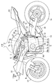
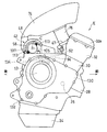
- FIG. 1 is a side view showing a motorcycle equipped with a supercharger according to a first embodiment of the present invention. It is the perspective view which looked at the principal part of the engine of the same motorcycle from back diagonally upward. It is a shaft arrangement
- left side and right side refer to the left and right sides as viewed from the driver who gets on the vehicle.
- FIG. 1 is a side view of a motorcycle equipped with a supercharger according to a first embodiment of the present invention.
- a body frame FR of the motorcycle has a main frame 1 that forms a front half portion, and a seat rail 2 that is attached to the rear portion of the main frame 1 and forms the rear half portion of the body frame FR.
- a front fork 8 is rotatably supported on a head pipe 4 provided at the front end of the main frame 1 via a steering shaft (not shown), and a front wheel 10 is attached to the front fork 8.
- a steering handle 6 is fixed to the upper end of the front fork 8.
- a swing arm 12 is pivotally supported by a rear end portion of the main frame 1 at the center lower portion of the vehicle body frame FR via a pivot shaft 16 so that the swing arm 12 can swing up and down. Is supported rotatably.
- An engine E is attached to the lower part of the main frame 1. The rotation of the engine E is transmitted to the transmission mechanism 11 such as a chain disposed on the left side of the vehicle body via the transmission 13, and the rear wheel 14 is driven via the transmission mechanism 11.
- the fuel tank 15 is arranged on the upper part of the main frame 1, and the driver's seat 18 and the passenger seat 20 are supported on the rear frame 2.
- a resin front cowl 22 that covers the front of the head pipe 4 is attached to the front of the vehicle body.
- the front cowl 22 is formed with an intake air intake 24 for taking in the intake air I to the engine E from the outside.
- Engine E is a 4-cylinder 4-cycle parallel multi-cylinder engine having a crankshaft 26 that is an engine rotation shaft extending in the vehicle width direction.
- the form of the engine E is not limited to this.
- the engine E includes a crankcase 28 that supports the crankshaft 26, a cylinder block 30 that is coupled to the top of the crankcase 28, a cylinder head 32 that is coupled to the top, and a head cover that is attached to the top of the cylinder head 32. 32a and an oil pan 34 attached to the lower part of the crankcase 28.
- the rear part of the crankcase 28 constitutes a transmission case that houses the transmission 13.
- the transmission cover 130 is detachably attached to the right side surface of the crankcase 28 by a plurality of bolts 132, and the transmission 13 can be removed by removing the transmission cover 130. ing.
- the cylinder block 30 and the cylinder head 32 in FIG. 1 are slightly inclined forward. More specifically, the piston axis of the engine E extends upward and inclined forward.
- An intake port 47 is provided at the rear of the cylinder head 32.
- Four exhaust pipes 36 connected to the exhaust port on the front surface of the cylinder head 32 are gathered below the engine E and connected to an exhaust muffler 38 disposed on the right side of the rear wheel 14.
- a supercharger 42 that takes in outside air and supplies it to the engine E as intake air I is disposed behind the cylinder block 30 and above the rear portion of the crankcase 28. That is, the supercharger 42 is located above the transmission 13.
- the supercharger 42 compresses the outside air sucked from the suction port 46, increases its pressure, discharges it from the discharge port 48, and supplies it to the engine E. Thereby, the amount of intake air supplied to the engine E can be increased.
- the suction port 46 of the supercharger 42 opens leftward above the rear portion of the crankcase 28, and the discharge port 48 opens upward near the center position in the vehicle width direction of the engine E.
- the supercharger 42 includes a supercharger rotating shaft 44 extending in the vehicle width direction, an impeller 50 that is a supercharging rotating body fixed to the supercharger rotating shaft 44, and an impeller 50. It includes an impeller housing 52 for covering, a transmission mechanism 54 for transmitting the power of the engine E to the impeller 50, and a casing 56 for covering most of the supercharger rotating shaft 44 and the transmission mechanism 54 from the radial direction.
- a speed increaser 54 formed of a planetary gear device described later is used as the transmission mechanism 54.
- the casing 56 is fixed to the upper surface of the crankcase 28 of the engine E by bolts (not shown).
- an opening OP is formed on the upper surface of the crankcase 28, and the casing 56 is fixed so as to cover the opening OP of the crankcase 28 from above.
- a later-described chain 94 (FIG. 3) that transmits power to the supercharger rotating shaft 44 passes through the opening OP.
- the speed increaser 54 and the air cleaner 40 are arranged in the vehicle width direction with the impeller housing 52 interposed therebetween.
- the impeller housing 52 is connected to the air cleaner 40 by a bolt (not shown).
- a cleaner outlet 62 of the air cleaner 40 is connected to the suction port 46 of the supercharger 42, and an intake duct 70 that introduces the traveling air A flowing in front of the cylinder block 30 to the turbocharger 42 is connected to the cleaner inlet 60 on the outer side in the vehicle width direction. Connected from.
- the cleaner inlet 60 and the outlet 70 b of the intake duct 70 are connected by connecting a plurality of bolts 55 to connecting flanges 63 and 65 provided on the outer periphery of each.
- a cleaner element 41 for purifying the intake air I is built in the connecting flanges 63 and 65.
- An intake chamber 74 is disposed between the discharge port 48 of the supercharger 42 and the intake port 47 of the engine E in FIG.
- the intake chamber 74 stores intake air I supplied from the supercharger 42 to the intake port 47.
- the intake chamber 74 is disposed above the supercharger 42, and most of the intake chamber 74 is located behind the cylinder block 30.
- the discharge port 48 of the supercharger 42 is connected to the central portion of the intake chamber 74 in the vehicle width direction. As a result, the intake air I from the supercharger 42 flows evenly into the plurality of intake ports 47 through the intake chamber 74.
- a throttle body 76 is disposed between the intake chamber 74 and the cylinder head 32.
- fuel is injected into the intake air to generate an air-fuel mixture, and this air-fuel mixture is supplied into the cylinder.
- the fuel tank 15 is disposed above the intake chamber 74 and the throttle body 76.
- the intake duct 70 is supported by the main frame 1 in such a manner that the front end opening 70a faces the intake intake 24 of the front cowl 22, and the traveling air A introduced from the opening 70a is boosted by the ram effect to be used as intake I. Introduced into the supercharger 42.
- the intake duct 70 is disposed on the left side of the vehicle body, and passes outside the cylinder block 30 and the cylinder head 32 of the engine E from below the front end of the handle 6 in a side view.
- a clutch gear 72 is provided at the right end, which is one side in the vehicle width direction of the crankshaft 26 of the engine E, and the supercharger that drives the supercharger 42 to the left of the clutch gear 72.
- a machine gear 80 is provided.
- a driven-side supercharger gear 84 that meshes with the supercharger gear 80 of the crankshaft 26 is spline-fitted so as to rotate integrally with the supercharger drive shaft 78.
- a starter gear 86 is supported on the supercharger drive shaft 78 so as to be relatively rotatable, and a starter one-way clutch 85 is interposed between the driven supercharger gear 84 and the starter gear 86.
- a starter motor 90 is connected to the starter gear 86 via a torque limiter 88.
- the starter one-way clutch 85 is connected and the starting torque is transmitted to the crankshaft 26. Further, when the rotational speed of the crankshaft 26 becomes faster than the starter motor 90 after the engine E is started, the starter one-way clutch 85 is disengaged and power transmission from the crankshaft 26 to the starter motor 90 is blocked.
- a first sprocket 92 is provided at the right end of the supercharger drive shaft 78. That is, the first sprocket 92 is provided on the right side (shaft end side) of the bearing 79 that supports the supercharger drive shaft 78.
- a chain 94 which is an endless power transmission member that transmits the power of the engine E to the supercharger 42, is stretched around the gear 92 a of the first sprocket 92.
- the chain 94 is disposed on the right side that is the opposite side of the suction port 46 of the supercharger 42 and the transmission mechanism 11 for driving the wheel in the vehicle width direction.
- the chain 94 is pressed by a tensioner 134 (FIG. 5) to apply tension. Thereby, adjustment between axes is unnecessary.
- Rotational force of the crankshaft 26 is transmitted from the supercharger drive shaft 78 to the input shaft 65 connected to the supercharger rotation shaft 44 via the chain 94.
- a second sprocket 96 is provided at the right end of the input shaft 65, and a chain 94 is stretched around a gear 96 a of the second sprocket 96.
- the input shaft 65 is a rotating shaft of the speed increaser 54.
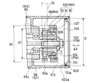
- the supercharger rotating shaft 44 and the input shaft 65 constitute a rotating shaft body RS in which an impeller 50 is provided at one end and a second sprocket 96 which is a rotating body that transmits power from the engine E is provided at the other end. is doing.
- the supercharger rotating shaft 44 and the input shaft 65 have a common axis C that matches the vehicle width direction.
- the second sprocket 96 constitutes a rotation transmission part that is a part of a transmission rotating body RM that transmits the power from the engine E to the rotating shaft body RS.
- the input shaft 65 is a hollow shaft and is rotatably supported by the casing 56 via a bearing 98.
- Spline teeth are formed on the outer peripheral surface of the right end portion 65b of the input shaft 65, and the second sprocket 96 is connected to the input shaft 65 via a gearbox one-way clutch 100 that is spline-fitted to the outer peripheral surface.
- the second sprocket 96 and the chain 94 are arranged on the right side, which is outside the vehicle body, with respect to the supported portion 65c supported by the bearing 98 in the input shaft 65.
- the speed increaser one-way clutch 100 is disposed outside the chain 94. In the present embodiment, the speed increaser one-way clutch 100 also constitutes a part of the transmission rotating body RM.
- the speed increaser one-way clutch 100 is provided between the second sprocket 96 and the supercharger rotating shaft 44 and suppresses rotational fluctuations of power.
- the step-up gear one-way clutch 100 has a clutch structure that releases the connection between the upstream side and the downstream side when the rotational speed on the downstream side exceeds the rotational speed on the upstream side. Since the speed-up gear one-way clutch 100 is disposed outside the chain 94, the design can be easily changed and the replacement is easy. However, the gearbox one-way clutch 100 may be disposed inside the chain 94.
- a female thread portion is formed on the inner peripheral surface of the right end portion 65 b of the input shaft 65, and the speed increaser one-way clutch 100 is moved by the head portion of the bolt 102 screwed into the female thread. It is attached to the right end portion 65b via the washer 104.
- These bolts 102 and washers 104 constitute an attachment member FM that detachably attaches the speed-up gear one-way clutch 100 that is the transmission rotator RM to the input shaft 65 that is the rotation shaft RS.
- the gearbox one-way clutch 100 includes a clutch cup 91 that forms a clutch outer ring 91 and rotates integrally with the input shaft 65, a clutch inner ring 93, and a clutch element 95 disposed between the clutch outer ring 91 and the clutch inner ring 93. And a second sprocket 96 is formed on the clutch inner ring 93.
- the second sprocket 96 is disposed on the inner side (left side in the vehicle width direction) of the axial direction AX of the rotary shaft body RS in the speed increaser one-way clutch 100.
- the outer diameter d1 of the second sprocket 96 is set smaller than the outer diameter d2 of the clutch cup 91 (d1 ⁇ d2).
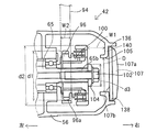
- the speed increaser one-way clutch 100, the second sprocket 96, and the bolt 102 are stored in a rotating body storage space 105 formed at the right end of the casing 56. That is, the casing 56 constitutes a supercharger case SC that houses the rotary shaft RS, the transmission rotator RM, and the attachment member FM. An opening 105 facing the outside of the vehicle body is formed at the right end of the casing 56, and the opening 105 is closed by a cap 107.
- the supercharger case SC may be formed so that it can be divided into a part that accommodates the transmission rotator RM and the attachment member FM and a part that accommodates the rotary shaft RS. Thereby, the opening 105 can be formed large, and a complicated case shape can be obtained.
- the opening 105 is an opening for accessing the transmission rotator RM and the attachment member FM from the axial direction AX of the rotary shaft RS, and the inner diameter D thereof is increased from that of the second sprocket 96 which is the transmission rotator RM.
- the speed machine one-way clutch 100 and the bolts 102 and washers 104 that are the attachment members FM are formed so as to pass therethrough (D> d2).
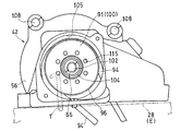
- FIG. 5 which is a side view of the engine viewed from the right side, the cap 107 is attached to the casing (supercharger case) 56 by a fastening member 113 such as a bolt from the vehicle width direction. That is, the cap 107 is fastened to the casing 56 by a fastening force along the axial direction AX of the rotary shaft RS.
- the fitting portion 4 is formed with a cylindrical fitting portion 111 that protrudes inward and fits into the opening 105.
- An annular seal member 109 is interposed between the inner peripheral surface 105 a of the opening 105 and the outer peripheral surface 111 a of the fitting portion 111.
- the engaging part 115 which consists of the through-hole which faced the axial center direction AX of rotating shaft RS is provided in the end surface of the clutch cup 91. As shown in FIG. The engaging portion 115 is provided so that the clutch cup 91 can be easily pulled out of the axial direction AX by engaging with a pulling tool inserted from the opening 105.
- the impeller 50 is fixed to the left end portion 44a of the supercharger rotating shaft 44 of the supercharger 42 in FIG. 3, and the left end portion 65a of the input shaft 65 is connected to the planetary gear device 106 that is the speed increaser 54.
- the left side 44b of the supercharger rotating shaft 44 is connected.
- the supercharger rotating shaft 44 is rotatably supported by the casing 56 via a bearing 99.
- the casing 56 includes an input shaft case portion 56R that supports the input shaft 65 and a rotation shaft case portion 56L that supports the supercharger rotation shaft 44.
- the input shaft case portion 56R and the rotation shaft case portion 56L are It is connected using a casing fastening member 108 such as a bolt.
- the impeller housing 52 is connected to the casing 56 using a housing fastening member 110 such as a bolt.
- the impeller housing 52 is formed with the suction port 46 opened on the left side and the discharge port 48 opened upward.
- the planetary gear unit 106 is disposed between the input shaft 65 and the supercharger rotating shaft 44 and supported by the casing 56.
- External teeth 112 are formed on the right end 44 b of the supercharger rotating shaft 44, and a plurality of planetary gears 114 are geared to the external teeth 112 side by side in the circumferential direction. That is, the external teeth 112 of the supercharger rotating shaft 44 function as the sun gear of the planetary gear device 106.
- the planetary gear 114 is gear-connected to a large-diameter internal gear (ring gear) 116 on the radially outer side.
- the planetary gear 114 is rotatably supported on the carrier shaft 122 by a bearing 120 attached to the casing 56.
- the carrier shaft 122 has a fixing member 118, and this fixing member 118 is fixed to the casing 56 with a bolt 124. That is, the carrier shaft 122 is fixed.
- An input gear 126 provided at the left end of the input shaft 65 is gear-coupled to the internal gear 116.
- the internal gear 116 is gear-connected so as to rotate in the same rotational direction as the input shaft 65, the carrier shaft 122 is fixed, and the planetary gear 114 rotates in the same rotational direction as the internal gear 116.
- the sun gear (external gear 112) is formed on the supercharger rotating shaft 44 serving as an output shaft, and rotates in the direction opposite to the planetary gear 114. That is, the planetary gear device 106 accelerates the rotation of the input shaft 65 and transmits it to the supercharger rotating shaft 44 in the rotation direction opposite to the input shaft 65.
- the supercharger drive shaft 78 rotates in conjunction with the crankshaft 26 by meshing between the supercharger gear 80 and the driven supercharger gear 84.
- the input shaft 65 rotates through the chain 94, and further, the supercharger rotary shaft 44 rotates through the planetary gear unit 106, and the supercharger 42 starts.
- the traveling wind A shown in FIG. 1 enters the intake duct 70 through the intake intake 24 and is compressed by dynamic pressure (ram pressure), passes through the intake duct 70, enters the air cleaner 40, and passes through the air cleaner 40. After being cleaned, it is introduced into the supercharger 42.
- the intake air I introduced into the supercharger 42 is pressurized by the supercharger 42 and introduced into the engine E through the intake chamber 74 and the throttle body 76. Due to the synergistic effect of the ram pressure and the pressurization by the supercharger 42, high-pressure intake air can be supplied to the engine E.
- FIG. 5 is a side view of the supercharger 42 with the cap 107 removed, as viewed from the right side.
- the bolt 102 is loosened, the bolt 102 and the washer 104 are removed from the input shaft 65 and taken out from the opening 105.
- the extraction tool T is engaged with the engaging portion (through hole) 115 of the speed increaser one-way clutch 100, and the transmission rotator RM including the second sprocket 96 and the speed increaser one-way clutch 100 is removed from the input shaft 65. Remove and remove from opening 105.
- the chain 94 When replacing the chain 94, the chain 94 can be removed from the second sprocket 96 by releasing the tension by the tensioner 134 (FIG. 5). In this way, the chain 94 that is likely to be loaded can be easily replaced. Further, since the second sprocket 96 can be attached and detached, sprockets having different diameters can be attached. Further, the first sprocket 92 can be easily replaced by loosening the bolt 132 of FIG. 5 and removing the mission cover 130. Thereby, the speed increasing ratio can be changed.
- the tool T is inserted from the opening 105 and the bolt 102 is operated to attach and detach the second sprocket 96 and the one-way clutch 100 from the input shaft 65. be able to. Thereby, workability
- the casing 56 fixed to the crankcase 28 and the input shaft 65 supported by the casing 56, the second sprocket 96, the gearbox one-way clutch 100, and the input shaft 65 can be attached and detached. Therefore, workability is further improved.
- the opening 105 is closed by a cap 107 that is detachable from the casing 56 shown in FIG. 4, it is possible to prevent foreign matter from entering through the opening 105.
- a seal member 109 is interposed between the inner peripheral surface 105a of the opening 105 and the outer peripheral surface 111a of the fitting portion 111 of the cap 107, and the cap 107 is fastened to the casing 56 by a fastening force along the axial direction AX. Therefore, a large fastening force for press-contacting the seal member 109 becomes unnecessary, and the number of fastening members can be reduced.
- the opening 105 is formed in a size that allows the second sprocket 96, the speed increaser one-way clutch 100, the bolt 102, and the washer 104 to pass through, the second sprocket 96, the speed increaser one-way clutch 100, the bolt 102, Since the washer 104 can be taken in and out from the opening 105, workability is further improved.
- the second sprocket 96 is formed in the clutch inner ring 93 of the speed increaser one-way clutch 100, it is not necessary to provide a separate sprocket wheel, and the structure is simplified.
- FIG. 7 shows a turbocharger 42 according to another example of the present invention.
- the inner diameter D of the opening 105 is set smaller than the outer diameter d1 of the second sprocket 96 and the outer diameter d2 of the clutch cup 91 (D ⁇ d1, D ⁇ d2), and the outer diameter d3 of the washer 104. (D3 ⁇ D).
- the axial clearance W1 between the input shaft 65 and the casing 56 is set to be larger than the width (axial dimension) W2 of the chain 94 (W2 ⁇ W1).
- a male screw 136 is formed on the outer periphery of the cap 107
- a female screw 138 is formed on the inner peripheral surface of the right end of the casing 56
- the cap 107 is screwed to the right end of the casing 56.
- a groove or a protrusion for angularly displacing the cap 107 around the axis is formed on the right end surface 107a of the cap 107.
- a groove (not shown) is formed in the right end surface 107 a of the cap 107, and the tool 107 is fitted in the groove (not shown) and rotated around the axis, thereby allowing the cap 107 to move relative to the casing 56. It can be removed.
- an abutting portion 140 with which the left end surface 107b of the cap 107 abuts is formed at the right end portion of the casing 56.
- the contact portion 140 is formed on the left side of the female screw 138, and an opening 105 is formed on the inner peripheral surface of the contact portion 140.
- the present invention is not limited to the above embodiment, and various additions, changes, or deletions are possible without departing from the gist of the present invention.
- the chain 94 is used as the power transmission member in the above embodiment, a belt or a gear train may be used.
- the sprocket 96 and the gearbox one-way clutch 100 are used as a rotary body, a pulley and a gear may be sufficient and a one-way clutch is not necessary.
- the supercharger 42 may be other types such as a root type, a re-sholm type, a scroll type, in addition to a centrifugal type provided with the impeller 50 as a supercharging rotator. Therefore, such a thing is also included in the scope of the present invention.
Landscapes
- Engineering & Computer Science (AREA)
- Mechanical Engineering (AREA)
- General Engineering & Computer Science (AREA)
- Chemical & Material Sciences (AREA)
- Combustion & Propulsion (AREA)
- Supercharger (AREA)
- Lubrication Of Internal Combustion Engines (AREA)
- General Details Of Gearings (AREA)
- Cylinder Crankcases Of Internal Combustion Engines (AREA)
Abstract
Dans la présente invention, un rouet (50), qui met l'air d'admission (I) d'un moteur (E) sous pression, est situé sur l'extrémité gauche (44a) de l'arbre de rotation de compresseur d'alimentation (44) d'un compresseur d'alimentation (42). L'énergie provenant du moteur (E) est transmise par l'intermédiaire d'une chaîne (94) à un second barbotin (96), placé sur l'extrémité droite (65b) de l'arbre d'entrée (65) d'un engrenage multiplicateur (54), et entraîne le compresseur d'alimentation (42). Le second barbotin (96) est fixé de façon détachable à l'arbre d'entrée (65) au moyen d'un boulon (102). L'arbre de rotation de compresseur d'alimentation (44), l'arbre d'entrée (65), le second barbotin (96) et le boulon (102) sont logés dans un carter de compresseur d'alimentation (56). Une ouverture (105), pour accéder au boulon (102) et au second barbotin (96) à partir de la direction centrale axiale, est formée sur la surface d'extrémité droite du carter de compresseur d'alimentation (56).
Priority Applications (4)
| Application Number | Priority Date | Filing Date | Title |
|---|---|---|---|
| JP2014524843A JP5945325B2 (ja) | 2012-07-11 | 2013-07-10 | エンジンの過給機 |
| CN201380036346.0A CN104428513B (zh) | 2012-07-11 | 2013-07-10 | 发动机的增压器 |
| EP13816004.9A EP2878788B1 (fr) | 2012-07-11 | 2013-07-10 | Compresseur d'alimentation de moteur |
| US14/591,803 US10190454B2 (en) | 2012-07-11 | 2015-01-07 | Motorcycle supercharger |
Applications Claiming Priority (2)
| Application Number | Priority Date | Filing Date | Title |
|---|---|---|---|
| JP2012-155463 | 2012-07-11 | ||
| JP2012155463 | 2012-07-11 |
Related Child Applications (1)
| Application Number | Title | Priority Date | Filing Date |
|---|---|---|---|
| US14/591,803 Continuation US10190454B2 (en) | 2012-07-11 | 2015-01-07 | Motorcycle supercharger |
Publications (1)
| Publication Number | Publication Date |
|---|---|
| WO2014010639A1 true WO2014010639A1 (fr) | 2014-01-16 |
Family
ID=49916088
Family Applications (3)
| Application Number | Title | Priority Date | Filing Date |
|---|---|---|---|
| PCT/JP2013/068915 Ceased WO2014010652A1 (fr) | 2012-07-11 | 2013-07-10 | Structure de montage de compresseur volumétrique pour moteur |
| PCT/JP2013/068900 Ceased WO2014010639A1 (fr) | 2012-07-11 | 2013-07-10 | Compresseur d'alimentation de moteur |
| PCT/JP2013/068916 Ceased WO2014010653A1 (fr) | 2012-07-11 | 2013-07-10 | Système de lubrification pour moteur de véhicule |
Family Applications Before (1)
| Application Number | Title | Priority Date | Filing Date |
|---|---|---|---|
| PCT/JP2013/068915 Ceased WO2014010652A1 (fr) | 2012-07-11 | 2013-07-10 | Structure de montage de compresseur volumétrique pour moteur |
Family Applications After (1)
| Application Number | Title | Priority Date | Filing Date |
|---|---|---|---|
| PCT/JP2013/068916 Ceased WO2014010653A1 (fr) | 2012-07-11 | 2013-07-10 | Système de lubrification pour moteur de véhicule |
Country Status (5)
| Country | Link |
|---|---|
| US (3) | US9869218B2 (fr) |
| EP (3) | EP2878787B1 (fr) |
| JP (3) | JP5944506B2 (fr) |
| CN (3) | CN104428510B (fr) |
| WO (3) | WO2014010652A1 (fr) |
Families Citing this family (25)
| Publication number | Priority date | Publication date | Assignee | Title |
|---|---|---|---|---|
| CN104471211B (zh) * | 2012-07-11 | 2017-04-19 | 川崎重工业株式会社 | 带增压器的发动机 |
| US9915192B2 (en) * | 2014-08-04 | 2018-03-13 | Jeffrey J. Buschur | Power conversion device |
| JP6156296B2 (ja) * | 2014-09-11 | 2017-07-05 | マツダ株式会社 | エンジンのオイル供給装置 |
| JP6142885B2 (ja) * | 2015-03-05 | 2017-06-07 | マツダ株式会社 | エンジンのオイル供給装置、エンジンの製造方法及びエンジンの給油路構造 |
| JP6601134B2 (ja) * | 2015-10-13 | 2019-11-06 | スズキ株式会社 | 4サイクル多気筒エンジン |
| JP6623680B2 (ja) * | 2015-10-27 | 2019-12-25 | スズキ株式会社 | 内燃機関の潤滑構造及び自動二輪車 |
| JP6627412B2 (ja) * | 2015-10-27 | 2020-01-08 | スズキ株式会社 | 内燃機関の潤滑構造及び自動二輪車 |
| JP6668681B2 (ja) * | 2015-10-27 | 2020-03-18 | スズキ株式会社 | 鞍乗型車両 |
| JP6551152B2 (ja) * | 2015-10-27 | 2019-07-31 | スズキ株式会社 | 内燃機関の潤滑構造及び自動二輪車 |
| US10167767B2 (en) | 2015-10-27 | 2019-01-01 | Suzuki Motor Corporation | Motorcycle and saddle-ridden type vehicle |
| US10018084B2 (en) * | 2015-10-27 | 2018-07-10 | Suzuki Motor Corporation | Lubricating structure of internal combustion engine and motorcycle |
| US10086903B2 (en) * | 2015-10-27 | 2018-10-02 | Suzuki Motor Corporation | Saddle-ridden vehicle |
| DE102016012781A1 (de) * | 2015-10-27 | 2017-04-27 | Suzuki Motor Corporation | Schmierstruktur eines Verbrennungsmotors und Motorrad |
| JP2017125432A (ja) * | 2016-01-13 | 2017-07-20 | ヤマハ発動機株式会社 | 自動二輪車 |
| US10378491B2 (en) * | 2016-03-08 | 2019-08-13 | K&N Engineering, Inc. | Aircharger air intake system and method |
| US10690045B2 (en) * | 2017-03-05 | 2020-06-23 | Southwest Research Institute | Intake air boost system for two-cycle engine having roots blowers |
| JP6437597B1 (ja) * | 2017-06-16 | 2018-12-12 | 本田技研工業株式会社 | 内燃機関 |
| US11680582B2 (en) * | 2017-09-25 | 2023-06-20 | Johnson Controls Tyco IP Holdings LLP | Two piece split scroll for centrifugal compressor |
| JP7040979B2 (ja) | 2018-03-29 | 2022-03-23 | 本田技研工業株式会社 | 内燃機関の油路構造 |
| EP3797219B1 (fr) | 2018-05-23 | 2026-04-08 | Cummins, Inc. | Système et procédé associés à un pignon captif dans un moteur |
| JP2019214979A (ja) * | 2018-06-13 | 2019-12-19 | スズキ株式会社 | 内燃機関 |
| MY196748A (en) * | 2018-09-25 | 2023-05-03 | Honda Motor Co Ltd | Power unit for straddle-type vehicles |
| JP7287261B2 (ja) | 2019-12-18 | 2023-06-06 | トヨタ紡織株式会社 | 吸気ダクト |
| CN113309846A (zh) * | 2020-02-27 | 2021-08-27 | Tvs电机股份有限公司 | 用于机动车辆的动力装置 |
| JP2021173242A (ja) * | 2020-04-28 | 2021-11-01 | ヤマハモーターパワープロダクツ株式会社 | V型ohvエンジン |
Citations (6)
| Publication number | Priority date | Publication date | Assignee | Title |
|---|---|---|---|---|
| JPH0270920A (ja) * | 1988-09-02 | 1990-03-09 | Yamaha Motor Co Ltd | 過給機付きエンジンを備えた自動二輪車 |
| JPH08189370A (ja) * | 1994-01-25 | 1996-07-23 | Komatsu Ltd | 差動駆動過給装置およびその制御方法 |
| JPH08232757A (ja) * | 1995-02-23 | 1996-09-10 | Yamaha Motor Co Ltd | エンジン |
| JP2001233276A (ja) * | 2000-02-24 | 2001-08-28 | Yamaha Motor Co Ltd | 過給機を備えた自動二輪車 |
| JP2008190426A (ja) * | 2007-02-05 | 2008-08-21 | Yanmar Co Ltd | エンジン |
| JP2011247267A (ja) * | 2011-07-14 | 2011-12-08 | Honda Motor Co Ltd | 内燃機関 |
Family Cites Families (52)
| Publication number | Priority date | Publication date | Assignee | Title |
|---|---|---|---|---|
| FR2129208A5 (fr) * | 1971-03-12 | 1972-10-27 | Berliet Automobiles | |
| DE2843248C2 (de) * | 1978-10-04 | 1984-08-23 | Klöckner-Humboldt-Deutz AG, 5000 Köln | Schmierölkreislauf für eine Brennkraftmaschine |
| JPS5893930A (ja) * | 1981-11-27 | 1983-06-03 | Honda Motor Co Ltd | 内燃機関におけるエアポンプの駆動方法 |
| JPS6138126A (ja) * | 1984-07-31 | 1986-02-24 | Yoichi Yamazaki | タ−ボチヤ−ジヤの焼付き防止装置 |
| JP2515316B2 (ja) * | 1987-03-10 | 1996-07-10 | マツダ株式会社 | エンジンの機械式過給装置 |
| DE3832013C2 (de) * | 1987-09-17 | 1996-08-01 | Dancho Zochev Dipl Ing Donkov | Hubkolben-Brennkraftmaschine mit Kurbelgehäuse-Ladeluftpumpen |
| JPH026289A (ja) * | 1988-06-23 | 1990-01-10 | Yamaha Motor Co Ltd | 過給機付きエンジンを備えた自動二輪車 |
| JPH0224282A (ja) * | 1988-07-11 | 1990-01-26 | Yamaha Motor Co Ltd | 過給機付きエンジンを備えた自動二輪車 |
| JPH0224283A (ja) * | 1988-07-11 | 1990-01-26 | Yamaha Motor Co Ltd | 過給機付きエンジンを備えた自動二輪車 |
| JP2716763B2 (ja) * | 1988-12-14 | 1998-02-18 | ヤマハ発動機株式会社 | 自動二輪車用エンジンのバランサ軸配置構造 |
| JPH02264117A (ja) * | 1989-03-31 | 1990-10-26 | Mazda Motor Corp | 機械式過給機付エンジンの吸気装置 |
| JPH05256146A (ja) * | 1992-03-12 | 1993-10-05 | Tochigi Fuji Ind Co Ltd | 機械式過給機 |
| GB2300450A (en) | 1994-01-25 | 1996-11-06 | Komatsu Mfg Co Ltd | Differential driving supercharger and method for controlling the same |
| US6105558A (en) * | 1995-05-12 | 2000-08-22 | Bushling; William | Supercharging apparatus |
| JPH08312498A (ja) * | 1995-05-17 | 1996-11-26 | Mitsubishi Motors Corp | 自動車の潤滑装置 |
| JPH09287466A (ja) * | 1996-04-23 | 1997-11-04 | Yamaha Motor Co Ltd | 過給エンジン搭載車両 |
| US5823159A (en) * | 1997-09-26 | 1998-10-20 | Southwest Research Institute | Independent valve train lubrication system |
| JPH11257084A (ja) * | 1998-03-17 | 1999-09-21 | Yanmar Diesel Engine Co Ltd | 内燃機関における過給機の潤滑装置 |
| JP2001233277A (ja) * | 2000-02-24 | 2001-08-28 | Yamaha Motor Co Ltd | 過給機を備えた自動二輪車 |
| AU2001243304A1 (en) * | 2000-02-29 | 2001-09-12 | Bombardier Inc. | Four stroke engine having blow-by ventilation system and lubrication system |
| US7000577B2 (en) * | 2000-02-29 | 2006-02-21 | Brp-Rotax Gmbh & Co. Kg | Modular engine family |
| US7299792B1 (en) * | 2000-09-22 | 2007-11-27 | Accessible Technologies, Inc. | Centrifugal compressor with improved lubrication system for gear-type transmission |
| JP2002276383A (ja) * | 2001-03-15 | 2002-09-25 | Nissan Diesel Motor Co Ltd | ターボ過給機付きエンジンの潤滑装置 |
| JP3928035B2 (ja) * | 2001-12-27 | 2007-06-13 | 株式会社エッチ・ケー・エス | 過給機 |
| JP2004270459A (ja) * | 2003-03-05 | 2004-09-30 | Komatsu Ltd | ターボチャージャ付きエンジンの潤滑装置 |
| WO2004094796A1 (fr) * | 2003-04-21 | 2004-11-04 | Preusse India (P) Ltd | Chargeur de moteur centrifuge entraine par un systeme d'engrenage combine et destine a un fonctionnement a plusieurs vitesses et procede de transmission de puissance |
| JP4384457B2 (ja) * | 2003-09-09 | 2009-12-16 | 本田技研工業株式会社 | エンジン |
| US7051824B1 (en) * | 2003-11-03 | 2006-05-30 | Accessible Technologies, Inc. | Supercharged motorcycle |
| US7469689B1 (en) * | 2004-09-09 | 2008-12-30 | Jones Daniel W | Fluid cooled supercharger |
| US7189052B2 (en) * | 2004-11-03 | 2007-03-13 | Accessible Technologies, Inc. | Centrifugal compressor having rotatable compressor case insert |
| JP4563824B2 (ja) * | 2005-01-18 | 2010-10-13 | 本田技研工業株式会社 | 自動二輪車用エンジン |
| JP4614853B2 (ja) * | 2005-09-26 | 2011-01-19 | ヤマハ発動機株式会社 | 過給機の取付構造 |
| CA2578729C (fr) * | 2006-02-24 | 2010-01-12 | Honda Motor Co., Ltd. | Structure d'entree d'air pour petit vehicule marin |
| US7549493B1 (en) * | 2006-02-28 | 2009-06-23 | Jones Daniel W | Wet belt supercharger drive for a motorcycle |
| CN101512127B (zh) * | 2006-09-08 | 2012-08-08 | 博格华纳公司 | 运行内燃机的方法和装置 |
| US7516727B2 (en) * | 2006-09-21 | 2009-04-14 | Kawasaki Jukogyo Kabushiki Kaisha | Vehicle combustion engine |
| GB2455950B (en) * | 2006-09-29 | 2011-06-01 | Komatsu Mfg Co Ltd | Variable turbo supercharger and method of driving the same |
| US8234867B2 (en) * | 2008-06-25 | 2012-08-07 | Ford Global Technologies, Llc | Turbocharger system for internal combustion engine with internal isolated turbocharger oil drainback passage |
| US20100031935A1 (en) * | 2008-08-05 | 2010-02-11 | Vandyne Ed | Super-turbocharger having a high speed traction drive and a continuously variable transmission |
| JP2010209885A (ja) * | 2009-03-12 | 2010-09-24 | Toyota Motor Corp | 潤滑油供給装置の制御装置 |
| JP2011077898A (ja) * | 2009-09-30 | 2011-04-14 | Fujitsu Ten Ltd | 表示装置、表示方法、および、プログラム |
| WO2011046098A1 (fr) | 2009-10-14 | 2011-04-21 | 川崎重工業株式会社 | Dispositif de compresseur volumétrique de moteur |
| JP5882059B2 (ja) * | 2009-10-14 | 2016-03-09 | 川崎重工業株式会社 | エンジンの過給機駆動装置 |
| EP2517953B1 (fr) | 2009-12-24 | 2020-01-01 | Kawasaki Jukogyo Kabushiki Kaisha | Véhicule motorisé à deux roues à compresseur volumétrique |
| JP5475517B2 (ja) * | 2010-03-23 | 2014-04-16 | ヤンマー株式会社 | エンジン |
| JP5689731B2 (ja) * | 2011-03-31 | 2015-03-25 | 本田技研工業株式会社 | 内燃機関用オイル供給装置 |
| US8955659B2 (en) * | 2011-03-31 | 2015-02-17 | Honda Motor Co., Ltd. | Internal combustion engine and supplying oil path structure for hydraulic clutch in internal combustion engine |
| JP5775758B2 (ja) * | 2011-07-26 | 2015-09-09 | 本田技研工業株式会社 | 軸受部の潤滑構造 |
| CN104619967B (zh) * | 2012-09-13 | 2017-10-27 | 川崎重工业株式会社 | 带增压器的发动机 |
| JP6208551B2 (ja) * | 2013-11-13 | 2017-10-04 | 川崎重工業株式会社 | 動力伝達装置 |
| CN105745422B (zh) * | 2013-11-18 | 2019-04-30 | 川崎重工业株式会社 | 发动机 |
| US10138823B2 (en) * | 2015-10-26 | 2018-11-27 | Kawasaki Jukogyo Kabushiki Kaisha | Combustion engine air intake system for motorcycle |
-
2013
- 2013-07-10 WO PCT/JP2013/068915 patent/WO2014010652A1/fr not_active Ceased
- 2013-07-10 EP EP13817115.2A patent/EP2878787B1/fr active Active
- 2013-07-10 EP EP13817301.8A patent/EP2873832B1/fr active Active
- 2013-07-10 EP EP13816004.9A patent/EP2878788B1/fr active Active
- 2013-07-10 WO PCT/JP2013/068900 patent/WO2014010639A1/fr not_active Ceased
- 2013-07-10 JP JP2014524856A patent/JP5944506B2/ja active Active
- 2013-07-10 WO PCT/JP2013/068916 patent/WO2014010653A1/fr not_active Ceased
- 2013-07-10 JP JP2014524843A patent/JP5945325B2/ja active Active
- 2013-07-10 CN CN201380036352.6A patent/CN104428510B/zh active Active
- 2013-07-10 JP JP2014524855A patent/JP6074426B2/ja active Active
- 2013-07-10 CN CN201380036346.0A patent/CN104428513B/zh active Active
- 2013-07-10 CN CN201380036361.5A patent/CN104428514B/zh active Active
-
2015
- 2015-01-06 US US14/590,888 patent/US9869218B2/en active Active
- 2015-01-07 US US14/591,803 patent/US10190454B2/en active Active
- 2015-01-08 US US14/592,667 patent/US9581059B2/en active Active
Patent Citations (6)
| Publication number | Priority date | Publication date | Assignee | Title |
|---|---|---|---|---|
| JPH0270920A (ja) * | 1988-09-02 | 1990-03-09 | Yamaha Motor Co Ltd | 過給機付きエンジンを備えた自動二輪車 |
| JPH08189370A (ja) * | 1994-01-25 | 1996-07-23 | Komatsu Ltd | 差動駆動過給装置およびその制御方法 |
| JPH08232757A (ja) * | 1995-02-23 | 1996-09-10 | Yamaha Motor Co Ltd | エンジン |
| JP2001233276A (ja) * | 2000-02-24 | 2001-08-28 | Yamaha Motor Co Ltd | 過給機を備えた自動二輪車 |
| JP2008190426A (ja) * | 2007-02-05 | 2008-08-21 | Yanmar Co Ltd | エンジン |
| JP2011247267A (ja) * | 2011-07-14 | 2011-12-08 | Honda Motor Co Ltd | 内燃機関 |
Non-Patent Citations (1)
| Title |
|---|
| See also references of EP2878788A4 * |
Also Published As
| Publication number | Publication date |
|---|---|
| CN104428514A (zh) | 2015-03-18 |
| EP2873832B1 (fr) | 2019-02-20 |
| CN104428513A (zh) | 2015-03-18 |
| JP5945325B2 (ja) | 2016-07-05 |
| CN104428510B (zh) | 2017-06-06 |
| EP2873832A4 (fr) | 2016-07-20 |
| EP2878788A1 (fr) | 2015-06-03 |
| CN104428514B (zh) | 2017-06-27 |
| US20150118025A1 (en) | 2015-04-30 |
| US9869218B2 (en) | 2018-01-16 |
| EP2878788A4 (fr) | 2016-08-03 |
| EP2878787A1 (fr) | 2015-06-03 |
| JPWO2014010652A1 (ja) | 2016-06-23 |
| JPWO2014010653A1 (ja) | 2016-06-23 |
| EP2878787B1 (fr) | 2019-08-21 |
| US20150159525A1 (en) | 2015-06-11 |
| EP2878787A4 (fr) | 2016-06-29 |
| WO2014010652A1 (fr) | 2014-01-16 |
| CN104428510A (zh) | 2015-03-18 |
| JP5944506B2 (ja) | 2016-07-05 |
| WO2014010653A1 (fr) | 2014-01-16 |
| CN104428513B (zh) | 2017-07-28 |
| US9581059B2 (en) | 2017-02-28 |
| US10190454B2 (en) | 2019-01-29 |
| JPWO2014010639A1 (ja) | 2016-06-23 |
| US20150114364A1 (en) | 2015-04-30 |
| EP2873832A1 (fr) | 2015-05-20 |
| JP6074426B2 (ja) | 2017-02-01 |
| EP2878788B1 (fr) | 2018-08-29 |
Similar Documents
| Publication | Publication Date | Title |
|---|---|---|
| JP5945325B2 (ja) | エンジンの過給機 | |
| JP6076978B2 (ja) | 過給機付きエンジン | |
| JP5964975B2 (ja) | 過給機付きエンジン | |
| JP5898776B2 (ja) | 過給機付きエンジン | |
| US10012306B2 (en) | Lubricating structure for power transmitting system | |
| EP3073093B1 (fr) | Compresseur d'alimentation de moteur | |
| JP5898775B2 (ja) | 過給機付きエンジン | |
| JP6204489B2 (ja) | エンジンの過給機 |
Legal Events
| Date | Code | Title | Description |
|---|---|---|---|
| 121 | Ep: the epo has been informed by wipo that ep was designated in this application |
Ref document number: 13816004 Country of ref document: EP Kind code of ref document: A1 |
|
| ENP | Entry into the national phase |
Ref document number: 2014524843 Country of ref document: JP Kind code of ref document: A |
|
| NENP | Non-entry into the national phase |
Ref country code: DE |
|
| WWE | Wipo information: entry into national phase |
Ref document number: 2013816004 Country of ref document: EP |