WO2014010652A1 - エンジンの過給機取付構造 - Google Patents
エンジンの過給機取付構造 Download PDFInfo
- Publication number
- WO2014010652A1 WO2014010652A1 PCT/JP2013/068915 JP2013068915W WO2014010652A1 WO 2014010652 A1 WO2014010652 A1 WO 2014010652A1 JP 2013068915 W JP2013068915 W JP 2013068915W WO 2014010652 A1 WO2014010652 A1 WO 2014010652A1
- Authority
- WO
- WIPO (PCT)
- Prior art keywords
- supercharger
- engine
- case
- crankcase
- mounting structure
- Prior art date
- Legal status (The legal status is an assumption and is not a legal conclusion. Google has not performed a legal analysis and makes no representation as to the accuracy of the status listed.)
- Ceased
Links
Images




Classifications
-
- F—MECHANICAL ENGINEERING; LIGHTING; HEATING; WEAPONS; BLASTING
- F01—MACHINES OR ENGINES IN GENERAL; ENGINE PLANTS IN GENERAL; STEAM ENGINES
- F01M—LUBRICATING OF MACHINES OR ENGINES IN GENERAL; LUBRICATING INTERNAL COMBUSTION ENGINES; CRANKCASE VENTILATING
- F01M11/00—Component parts, details or accessories, not provided for in, or of interest apart from, groups F01M1/00 - F01M9/00
- F01M11/02—Arrangements of lubricant conduits
-
- F—MECHANICAL ENGINEERING; LIGHTING; HEATING; WEAPONS; BLASTING
- F01—MACHINES OR ENGINES IN GENERAL; ENGINE PLANTS IN GENERAL; STEAM ENGINES
- F01M—LUBRICATING OF MACHINES OR ENGINES IN GENERAL; LUBRICATING INTERNAL COMBUSTION ENGINES; CRANKCASE VENTILATING
- F01M1/00—Pressure lubrication
- F01M1/02—Pressure lubrication using lubricating pumps
-
- F—MECHANICAL ENGINEERING; LIGHTING; HEATING; WEAPONS; BLASTING
- F01—MACHINES OR ENGINES IN GENERAL; ENGINE PLANTS IN GENERAL; STEAM ENGINES
- F01M—LUBRICATING OF MACHINES OR ENGINES IN GENERAL; LUBRICATING INTERNAL COMBUSTION ENGINES; CRANKCASE VENTILATING
- F01M11/00—Component parts, details or accessories, not provided for in, or of interest apart from, groups F01M1/00 - F01M9/00
- F01M11/03—Mounting or connecting of lubricant purifying means relative to the machine or engine; Details of lubricant purifying means
-
- F—MECHANICAL ENGINEERING; LIGHTING; HEATING; WEAPONS; BLASTING
- F01—MACHINES OR ENGINES IN GENERAL; ENGINE PLANTS IN GENERAL; STEAM ENGINES
- F01M—LUBRICATING OF MACHINES OR ENGINES IN GENERAL; LUBRICATING INTERNAL COMBUSTION ENGINES; CRANKCASE VENTILATING
- F01M5/00—Heating, cooling, or controlling temperature of lubricant; Lubrication means facilitating engine starting
- F01M5/002—Cooling
-
- F—MECHANICAL ENGINEERING; LIGHTING; HEATING; WEAPONS; BLASTING
- F02—COMBUSTION ENGINES; HOT-GAS OR COMBUSTION-PRODUCT ENGINE PLANTS
- F02B—INTERNAL-COMBUSTION PISTON ENGINES; COMBUSTION ENGINES IN GENERAL
- F02B33/00—Engines characterised by provision of pumps for charging or scavenging
-
- F—MECHANICAL ENGINEERING; LIGHTING; HEATING; WEAPONS; BLASTING
- F02—COMBUSTION ENGINES; HOT-GAS OR COMBUSTION-PRODUCT ENGINE PLANTS
- F02B—INTERNAL-COMBUSTION PISTON ENGINES; COMBUSTION ENGINES IN GENERAL
- F02B33/00—Engines characterised by provision of pumps for charging or scavenging
- F02B33/32—Engines with pumps other than of reciprocating-piston type
- F02B33/34—Engines with pumps other than of reciprocating-piston type with rotary pumps
-
- F—MECHANICAL ENGINEERING; LIGHTING; HEATING; WEAPONS; BLASTING
- F02—COMBUSTION ENGINES; HOT-GAS OR COMBUSTION-PRODUCT ENGINE PLANTS
- F02B—INTERNAL-COMBUSTION PISTON ENGINES; COMBUSTION ENGINES IN GENERAL
- F02B33/00—Engines characterised by provision of pumps for charging or scavenging
- F02B33/32—Engines with pumps other than of reciprocating-piston type
- F02B33/34—Engines with pumps other than of reciprocating-piston type with rotary pumps
- F02B33/40—Engines with pumps other than of reciprocating-piston type with rotary pumps of non-positive-displacement type
-
- F—MECHANICAL ENGINEERING; LIGHTING; HEATING; WEAPONS; BLASTING
- F02—COMBUSTION ENGINES; HOT-GAS OR COMBUSTION-PRODUCT ENGINE PLANTS
- F02B—INTERNAL-COMBUSTION PISTON ENGINES; COMBUSTION ENGINES IN GENERAL
- F02B39/00—Component parts, details, or accessories relating to, driven charging or scavenging pumps, not provided for in groups F02B33/00 - F02B37/00
- F02B39/02—Drives of pumps; Varying pump drive gear ratio
- F02B39/04—Mechanical drives; Variable-gear-ratio drives
-
- F—MECHANICAL ENGINEERING; LIGHTING; HEATING; WEAPONS; BLASTING
- F02—COMBUSTION ENGINES; HOT-GAS OR COMBUSTION-PRODUCT ENGINE PLANTS
- F02B—INTERNAL-COMBUSTION PISTON ENGINES; COMBUSTION ENGINES IN GENERAL
- F02B39/00—Component parts, details, or accessories relating to, driven charging or scavenging pumps, not provided for in groups F02B33/00 - F02B37/00
- F02B39/02—Drives of pumps; Varying pump drive gear ratio
- F02B39/12—Drives characterised by use of couplings or clutches therein
-
- F—MECHANICAL ENGINEERING; LIGHTING; HEATING; WEAPONS; BLASTING
- F02—COMBUSTION ENGINES; HOT-GAS OR COMBUSTION-PRODUCT ENGINE PLANTS
- F02B—INTERNAL-COMBUSTION PISTON ENGINES; COMBUSTION ENGINES IN GENERAL
- F02B61/00—Adaptations of engines for driving vehicles or for driving propellers; Combinations of engines with gearing
- F02B61/02—Adaptations of engines for driving vehicles or for driving propellers; Combinations of engines with gearing for driving cycles
-
- F—MECHANICAL ENGINEERING; LIGHTING; HEATING; WEAPONS; BLASTING
- F02—COMBUSTION ENGINES; HOT-GAS OR COMBUSTION-PRODUCT ENGINE PLANTS
- F02B—INTERNAL-COMBUSTION PISTON ENGINES; COMBUSTION ENGINES IN GENERAL
- F02B67/00—Engines characterised by the arrangement of auxiliary apparatus not being otherwise provided for, e.g. the apparatus having different functions; Driving auxiliary apparatus from engines, not otherwise provided for
- F02B67/10—Engines characterised by the arrangement of auxiliary apparatus not being otherwise provided for, e.g. the apparatus having different functions; Driving auxiliary apparatus from engines, not otherwise provided for of charging or scavenging apparatus
-
- F—MECHANICAL ENGINEERING; LIGHTING; HEATING; WEAPONS; BLASTING
- F04—POSITIVE - DISPLACEMENT MACHINES FOR LIQUIDS; PUMPS FOR LIQUIDS OR ELASTIC FLUIDS
- F04D—NON-POSITIVE-DISPLACEMENT PUMPS
- F04D17/00—Radial-flow pumps, e.g. centrifugal pumps; Helico-centrifugal pumps
- F04D17/08—Centrifugal pumps
- F04D17/10—Centrifugal pumps for compressing or evacuating
-
- F—MECHANICAL ENGINEERING; LIGHTING; HEATING; WEAPONS; BLASTING
- F04—POSITIVE - DISPLACEMENT MACHINES FOR LIQUIDS; PUMPS FOR LIQUIDS OR ELASTIC FLUIDS
- F04D—NON-POSITIVE-DISPLACEMENT PUMPS
- F04D25/00—Pumping installations or systems
- F04D25/02—Units comprising pumps and their driving means
-
- F—MECHANICAL ENGINEERING; LIGHTING; HEATING; WEAPONS; BLASTING
- F04—POSITIVE - DISPLACEMENT MACHINES FOR LIQUIDS; PUMPS FOR LIQUIDS OR ELASTIC FLUIDS
- F04D—NON-POSITIVE-DISPLACEMENT PUMPS
- F04D25/00—Pumping installations or systems
- F04D25/02—Units comprising pumps and their driving means
- F04D25/022—Units comprising pumps and their driving means comprising a yielding coupling, e.g. hydraulic
-
- F—MECHANICAL ENGINEERING; LIGHTING; HEATING; WEAPONS; BLASTING
- F04—POSITIVE - DISPLACEMENT MACHINES FOR LIQUIDS; PUMPS FOR LIQUIDS OR ELASTIC FLUIDS
- F04D—NON-POSITIVE-DISPLACEMENT PUMPS
- F04D25/00—Pumping installations or systems
- F04D25/02—Units comprising pumps and their driving means
- F04D25/028—Units comprising pumps and their driving means the driving means being a planetary gear
-
- F—MECHANICAL ENGINEERING; LIGHTING; HEATING; WEAPONS; BLASTING
- F04—POSITIVE - DISPLACEMENT MACHINES FOR LIQUIDS; PUMPS FOR LIQUIDS OR ELASTIC FLUIDS
- F04D—NON-POSITIVE-DISPLACEMENT PUMPS
- F04D29/00—Details, component parts, or accessories
- F04D29/05—Shafts or bearings, or assemblies thereof, specially adapted for elastic fluid pumps
- F04D29/053—Shafts
- F04D29/054—Arrangements for joining or assembling shafts
-
- F—MECHANICAL ENGINEERING; LIGHTING; HEATING; WEAPONS; BLASTING
- F04—POSITIVE - DISPLACEMENT MACHINES FOR LIQUIDS; PUMPS FOR LIQUIDS OR ELASTIC FLUIDS
- F04D—NON-POSITIVE-DISPLACEMENT PUMPS
- F04D29/00—Details, component parts, or accessories
- F04D29/60—Mounting; Assembling; Disassembling
- F04D29/601—Mounting; Assembling; Disassembling specially adapted for elastic fluid pumps
-
- F—MECHANICAL ENGINEERING; LIGHTING; HEATING; WEAPONS; BLASTING
- F04—POSITIVE - DISPLACEMENT MACHINES FOR LIQUIDS; PUMPS FOR LIQUIDS OR ELASTIC FLUIDS
- F04D—NON-POSITIVE-DISPLACEMENT PUMPS
- F04D29/00—Details, component parts, or accessories
- F04D29/60—Mounting; Assembling; Disassembling
- F04D29/62—Mounting; Assembling; Disassembling of radial or helico-centrifugal pumps
- F04D29/624—Mounting; Assembling; Disassembling of radial or helico-centrifugal pumps especially adapted for elastic fluid pumps
-
- F—MECHANICAL ENGINEERING; LIGHTING; HEATING; WEAPONS; BLASTING
- F01—MACHINES OR ENGINES IN GENERAL; ENGINE PLANTS IN GENERAL; STEAM ENGINES
- F01M—LUBRICATING OF MACHINES OR ENGINES IN GENERAL; LUBRICATING INTERNAL COMBUSTION ENGINES; CRANKCASE VENTILATING
- F01M11/00—Component parts, details or accessories, not provided for in, or of interest apart from, groups F01M1/00 - F01M9/00
- F01M11/02—Arrangements of lubricant conduits
- F01M2011/021—Arrangements of lubricant conduits for lubricating auxiliaries, e.g. pumps or turbo chargers
-
- F—MECHANICAL ENGINEERING; LIGHTING; HEATING; WEAPONS; BLASTING
- F01—MACHINES OR ENGINES IN GENERAL; ENGINE PLANTS IN GENERAL; STEAM ENGINES
- F01M—LUBRICATING OF MACHINES OR ENGINES IN GENERAL; LUBRICATING INTERNAL COMBUSTION ENGINES; CRANKCASE VENTILATING
- F01M11/00—Component parts, details or accessories, not provided for in, or of interest apart from, groups F01M1/00 - F01M9/00
- F01M11/02—Arrangements of lubricant conduits
- F01M2011/022—Arrangements of lubricant conduits for lubricating cylinders
-
- F—MECHANICAL ENGINEERING; LIGHTING; HEATING; WEAPONS; BLASTING
- F01—MACHINES OR ENGINES IN GENERAL; ENGINE PLANTS IN GENERAL; STEAM ENGINES
- F01M—LUBRICATING OF MACHINES OR ENGINES IN GENERAL; LUBRICATING INTERNAL COMBUSTION ENGINES; CRANKCASE VENTILATING
- F01M11/00—Component parts, details or accessories, not provided for in, or of interest apart from, groups F01M1/00 - F01M9/00
- F01M11/02—Arrangements of lubricant conduits
- F01M2011/026—Arrangements of lubricant conduits for lubricating crankshaft bearings
-
- F—MECHANICAL ENGINEERING; LIGHTING; HEATING; WEAPONS; BLASTING
- F05—INDEXING SCHEMES RELATING TO ENGINES OR PUMPS IN VARIOUS SUBCLASSES OF CLASSES F01-F04
- F05D—INDEXING SCHEME FOR ASPECTS RELATING TO NON-POSITIVE-DISPLACEMENT MACHINES OR ENGINES, GAS-TURBINES OR JET-PROPULSION PLANTS
- F05D2220/00—Application
- F05D2220/40—Application in turbochargers
Definitions
- the present invention relates to an engine supercharger mounting structure in which a supercharger is mounted on an engine mounted on a vehicle such as a motorcycle.
- Some engines mounted on vehicles such as motorcycles are provided with a supercharger that pressurizes outside air to supply the engine to the engine (for example, Patent Document 1).
- This supercharger is configured to be driven in conjunction with the rotation of the engine rotation shaft, and as a merit of providing it, there is an increase in intake efficiency of intake air and an improvement in engine output.
- Some turbochargers as described above have a pumping unit that pumps intake air into the engine, and a speed increasing unit that increases the rotational speed of the engine rotation shaft and transmits it to the pumping unit. If these pumping section and speed increasing section are separately attached to the engine body, the workability of assembling and detaching the supercharger decreases.
- the present invention has been made in view of the above problems, and an object of the present invention is to provide an engine supercharger mounting structure in which a supercharger can be easily assembled to or removed from an engine body. .
- the supercharger mounting structure for an engine includes: a supercharger that pumps intake air into the engine; and a rotational speed of an engine rotation shaft that increases the rotational speed of the engine.
- the transmission includes a speed increasing portion and a supercharger case that accommodates the pressure feeding portion and the speed increasing portion, and the supercharger case is detachably attached to the crankcase of the engine.
- the turbocharger case detachably attached to the engine crankcase accommodates the turbocharger pumping section and the speed increasing section, and the pumping section, the speed increasing section, and the turbocharger case form one assembly. Therefore, the turbocharger can be easily assembled and removed from the engine.
- an opening is formed in an upper portion of the crankcase, and the power of the engine is transmitted to the speed increasing portion by a power transmission body extending through the opening.
- the power transmission body since the power transmission body extends through the opening, even when the supercharger is arranged above the crankcase, the power transmission body is arranged at a position close to the axial direction of the supercharger. Thus, the engine power can be smoothly transmitted to the supercharger.
- the supercharger case has a case main body that covers an upper portion of the crankcase, and a pressure feeding portion housing that houses the pressure feeding portion, and the pressure feeding portion housing is connected to the case main body. And it is preferable that a part protrudes below rather than the lower surface of the said case main body. According to this configuration, it is possible to prevent the vertical dimension of the case body from increasing in size by forming the pressure feeding portion housing and the case body separately.
- the upper surface of the crankcase is in contact with the case main body, and in the axial direction of the pressure feeding part housing and the supercharger. It is preferable that the opposite surface is formed below the contact surface. According to this configuration, since the facing surface is formed below the contact surface, the upper surface of the crankcase and the pumping portion housing are prevented from interfering with each other, while the turbocharger is moved upward from the crankcase. The amount of protrusion can be suppressed.
- the upper surface of the crankcase is further extended in the axial direction of the pumping portion from the opposed surface to the opposite side of the contact surface. It is preferable that a surface is formed, and the extended surface is formed below the contact surface together with the facing surface. According to this configuration, for example, the intake duct connected to the pumping unit can be easily disposed on the extended surface.
- a support portion for the rotating shaft is accommodated in the supercharger case so that the rotating shaft of the pressure feeding portion is located above the upper surface of the crankcase. According to this configuration, even if the rotating body of the pumping unit, for example, the impeller is disposed above the crankcase, the rotating shaft support portion is housed in the supercharger case, so that the vertical direction between the rotating body and the crankcase Can prevent interference.
- a drive shaft that is rotationally connected to the engine rotation shaft and drives the supercharger is supported by the crankcase, and a switching mechanism that switches a power path of the supercharger is attached to the drive shaft, It is preferable that a change drum for operating the switching mechanism via a shift fork is housed in the supercharger case. According to this configuration, since the change drum is also housed in the supercharger case, the change drum can be easily assembled.
- the change drum or the shift fork preferably extends through an opening formed in an upper portion of the crankcase. According to this configuration, since the change drum or the shift fork extends through the opening, it is easier to arrange the change drum and the shift fork inside the engine as compared with the case where they are arranged on the side surface of the crankcase.
- a shifter driving means for driving the change drum is detachably attached to the supercharger case. According to this configuration, the shift fork can be fitted into the supercharger case in a state before the shifter driving means is attached, and assemblability is improved.
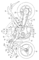
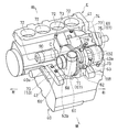
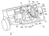
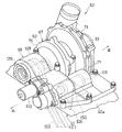
- FIG. 1 is a side view showing a motorcycle equipped with an engine equipped with a supercharger mounting structure according to a first embodiment of the present invention. It is a back perspective view showing the state where a part of the engine was removed. It is a back perspective view showing the state where the upper part of the engine was removed. It is a back perspective view which shows the state which removed the main body case of the supercharger from FIG.
- left side and right side refer to the left and right sides as viewed from the driver who gets on the vehicle.
- FIG. 1 is a side view of a motorcycle which is a kind of saddle riding type vehicle equipped with an engine according to an embodiment of the present invention.
- the motorcycle body frame FR includes a main frame 1 that forms a front half portion, and a seat rail 2 and a reinforcing rail 2a that are attached to the rear portion of the main frame 1 and form the rear half portion of the body frame FR.
- a front fork 8 is pivotally supported by a head pipe 4 integrally formed at the front end of the main frame 1 via a steering shaft (not shown), and a front wheel 10 is attached to the front fork 8. That is, the head pipe 4 functions as a handle post, and the main frame 1 that is a part of the vehicle body frame FR extends from the head pipe 4 to the rear of the vehicle body.
- a steering handle 6 is fixed to the upper end of the front fork 8.
- a swing arm bracket 12 is provided at the rear end of the main frame 1 which is the lower center of the vehicle body frame FR.
- a swing arm 20 is pivotally supported by the swing arm bracket 12 so as to be swingable up and down, and a rear wheel 22 is rotatably supported around a pivot shaft 23 at a rear end portion of the swing arm 20.
- An engine E is attached to the front side of the swing arm bracket 12 at the lower center of the vehicle body frame FR. The rotation of the engine E is transmitted to a transmission mechanism 24 such as a chain, and the rear wheel 22 is driven via the transmission mechanism 24.
- the engine E is, for example, a 4-cylinder 4-cycle parallel multi-cylinder engine. The form of the engine E is not limited to this.
- a rear cushion mechanism 25 is coupled between the rear frame 2 and the swing arm 20 to buffer a load applied between the rear wheel 22 and the rear frame 2.
- the fuel tank 28 is disposed on the upper part of the main frame 1, and a driver seat 30 and a passenger seat 32 are supported on the rear frame 2.
- a resin cowling 34 that covers a portion from the front of the head pipe 4 to the side of the front portion of the vehicle body is attached to the front portion of the vehicle body.
- a headlamp unit 36 is attached to the cowling 34, and an air intake port 38 is formed below the headlamp unit 36 to take in intake air into the engine E.
- the air intake port 38 is disposed on the front surface of the cowling 34 and is disposed at the front end portion of the cowling 34 having the highest traveling wind pressure.
- the air intake port 38 is located below the headlamp unit 36, but may be located above the headlamp unit 36, or may have two lamps separated in the vehicle width direction. You may locate in the middle of the vehicle width direction of a lamp-type headlamp.
- the engine E is attached to a crankcase 40 that supports an engine rotation shaft 39 extending in the vehicle width direction, a cylinder block 42 that protrudes upward from the crankcase 40, a cylinder head 44 above the cylinder block 42, and an upper portion of the cylinder head 44.
- a head cover 46 that covers the cam mechanism (not shown) of the intake / exhaust valve and an oil pan 50 provided below the crankcase 40 are provided.
- the rear part of the crankcase 40 also serves as a transmission case.
- the cylinder block 42 is slightly inclined forward.
- An intake port 47 is provided at the rear of the cylinder head 44.
- Four exhaust pipes 54 connected to the exhaust port on the front surface of the cylinder head 44 are gathered below the engine E and connected to an exhaust muffler 56 disposed on the right side of the rear wheel 22.
- a supercharger 62 that constitutes an intake section that takes in outside air and supplies it to the engine E is disposed behind the cylinder block 42 and above the crankcase 40.
- the supercharger 62 includes a supercharger rotating shaft 64 extending in the vehicle width direction, a suction port 66 opened leftward above the crankcase 40, and a supercharger rotating shaft 64 at the center of the engine E in the vehicle width direction. Also has a discharge port 68 positioned rearward.
- the suction port 66 of the supercharger 62 is arranged on the inner side in the vehicle width direction from the left side surface of the cylinder block 42, and the intake duct for introducing the traveling wind A flowing in front of the cylinder block 42 into the supercharger 62 at the suction port 66. 70 is connected.
- the intake duct 70 is disposed on the left side, which is one side of the engine E, and has an upstream ram duct unit 51 and a downstream intake duct portion 53.
- the ram duct unit 51 is supported by the main frame 1 in such a manner that the front end opening 51a faces the air intake port 38 of the cowling 34, and boosts the air introduced from the front end opening 51a by the ram effect.
- a front end portion 53 a of the suction duct portion 53 is connected to the rear end portion 51 b of the ram duct unit 51.
- the rear end portion 53 b of the suction duct portion 53 is connected to the suction port 66 of the supercharger 62.
- the air cleaner 55 for purifying the air to be introduced into the supercharger 62 is built in the connecting portion between the rear end portion 51b of the ram duct unit 51 and the front end portion 53a of the suction duct portion 53 of FIG.
- an air reservoir 57 having a channel area larger than that of other portions of the suction duct 53 is formed at the downstream end of the suction duct 53.
- the air reservoir 57 is located behind the cylinder block 42, and the suction port 66 of the supercharger 62 is connected to the outlet thereof.
- the discharge port 68 of the supercharger 62 faces upward, and the intake port is supplied from the supercharger 62 between the discharge port 68 and the four intake ports 47 (FIG. 1) of the engine E in the front-rear direction.
- An intake chamber 74 for storing intake air toward 47 (FIG. 1) is disposed.
- the intake chamber 74 has a width dimension extending over almost the entire length of the engine E in the vehicle width direction, and is disposed behind the cylinder block 42 above the supercharger 62 as shown in FIG.
- a throttle body 76 is disposed between the intake chamber 74 and the cylinder head 44.
- fuel is injected into the intake air to generate an air-fuel mixture, and this air-fuel mixture is supplied from each intake port 47 to the combustion chambers 72 (FIG. 2) in the four cylinder bores of the engine E.
- the fuel tank 28 is disposed above the intake chamber 74 and the throttle body 76.
- the supercharger 62 includes a pumping unit 61 that pumps intake air to the engine E, and a speed increasing unit that increases the rotational speed of the engine rotation shaft 39 (FIG. 1) and transmits it to the pumping unit 61.
- the pressure feeding unit 61 and the speed increasing unit 63 are accommodated in a supercharger case 67, and the supercharger case 67 is detachably attached to the crankcase 40 of the engine E.
- the supercharger case 67 includes a case main body 69 that covers the upper portion of the crankcase 40 and a pressure feeding unit housing 71 that houses the pressure feeding unit 61.
- the case main body 69 is attached to the upper surface 40 a of the crankcase 40 by a plurality of bolts 73, and the pumping portion housing 71 is connected to the case main body 69 by a housing fastening member 118.
- the pressure feeding unit 61 includes an impeller as a rotor, and discharges the outside air guided to the suction port 66 by rotating the impeller while increasing the pressure from the discharge port 68.
- the impeller rotates when the rotation of the engine rotation shaft 39 (FIG. 1) is transmitted.
- the pumping portion housing 71 is formed in a bowl shape.
- the suction port 66 is open to the shaft end portion on the opposite side of the speed increasing portion 63 in the pressure feeding portion housing 71, specifically, to the left side.
- the discharge port 68 is formed in the outer peripheral part of the pumping part housing 71, and is opened to the radial direction of the rotating shaft C of a supercharger, specifically, the upper side.
- the discharge port 68 is disposed near the center of the multi-cylinder engine E in the width direction (left-right direction), thereby suppressing non-uniform intake air in the intake chamber 74 and suppressing variations in pumping amount to each cylinder. it can.
- the speed increasing portion 63 is a mechanism that transmits the rotation of the engine rotation shaft 39 (FIG. 1) to the impeller, and a gear group that increases the output rotation and transmits the rotation to the impeller relative to the input rotation. Is provided. Thereby, the said impeller can be rotated at high speed.
- the supercharger case 67 includes a support portion that rotatably supports the impeller and the gear group. Since the pumping part 61 and the speed increasing part 63 are connected on the same axis C, the protruding dimension of the turbocharger case 67 from the crankcase 40 is reduced. Details of the pressure feeding unit 61 and the speed increasing unit 63 will be described later.
- the case main body 69 has a speed increasing portion storing portion 75 for storing the speed increasing portion 63 and a drum storing portion 77 for storing a change drum 108 (FIG. 5) described later.
- the case main body 69 is supported on the upper surface 40a of the crankcase 40 with the drum storage portion 77 and the speed increasing portion storage portion 75 aligned in the front-rear direction.
- a part of the pumping portion housing 71 protrudes below the lower surface 69 d of the case main body 69 in a state where it is connected to the left end of the speed increasing portion accommodating portion 75 of the case main body 69.
- An opening 150 is formed in the upper surface 40a of the crankcase 40, and the opening 150 is closed by a case body 69 supported by the upper surface 40a of the crankcase 40. That is, the case main body 69 in FIG. 3 also functions as a lid portion for the opening 150. As shown in FIG. 4, the opening 150 is formed near the right end of the crankcase 40 and slightly inside the right end. Thereby, it is easy to arrange the supercharger 62 inside.
- the upper surface 40 a of the crankcase 40 is formed with a contact surface 152 that contacts the case main body 69 and a first facing surface 154 that faces the pumping portion housing 71 in the axial direction.
- the first facing surface 154 is located below the contact surface 152, and forms a stepped portion that falls from the contact surface 152 at an angle of approximately 90 °.
- An extension surface 156 extending in the axial direction of the supercharger rotating shaft 64 is further formed on the upper surface 40a of the crankcase 40 on the side opposite to the contact surface 152 (left side in FIG. 3) from the first facing surface 154. . Therefore, the extension surface 156 is also positioned below the contact surface 152 together with the first facing surface 154.
- a cylindrical case flange 69a is formed at a position where the speed increasing portion accommodating portion 75 of the case body 69 is connected to the pressure feeding portion housing 71, and a second facing surface 155 facing the case flange 69a on the upper surface 40a of the crankcase 40 is also formed. It is recessed downward from the contact surface 152.
- a planetary gear device 112 (FIG. 6), which will be described later, is housed inside the case flange 69a.
- An oil hole 157a opened upward is formed in the partition wall 157 between the first facing surface 154 and the second facing surface 155, and this oil hole 157a allows the lubricating oil of the supercharger 62 and the planetary gear device 112 to flow. It communicates with the oil passage.
- a space between the case main body 69 (FIG. 3) and the upper surface 40a of the crankcase 40 is sealed by a single frame-shaped seal member 158.
- the seal member 158 is made of, for example, a rubber plate. This simplifies the seal structure.
- a through hole 160 constituting a part of the oil passage is formed in a portion corresponding to the oil hole 157 a in the seal member 158. Thereby, oil leakage can be effectively prevented.
- the crankshaft 39 that is the rotating shaft of the engine E is provided with a crank gear 80 for driving a countershaft 78 having an axis parallel to the crankshaft 39.
- a supercharger drive shaft 82 is disposed on the opposite side of the crankshaft 39.
- the counter shaft 78 and the supercharger drive shaft 82 are supported by the crankcase 40.
- a drive gear 84 that meshes with the crank gear 80 of the crankshaft 39 is spline-fitted so as to rotate integrally with the countershaft 78.
- a starter gear 86 is supported on the counter shaft 78 so as to be relatively rotatable, and a one-way clutch 85 is interposed between the drive gear 84 and the starter gear 86.
- a starter motor 90 is connected to the starter gear 86 via a torque limiter 88.
- the starter motor 90 rotates while the engine E is stopped, the one-way clutch 85 is connected and the starting torque is transmitted to the crankshaft 39. Further, when the rotational speed of the crankshaft 39 becomes faster than the starter motor 90 after the engine E is started, the one-way clutch 85 is disengaged and power transmission from the crankshaft 39 to the starter motor 90 is blocked.
- the starter motor 90 is arranged side by side with the drum housing portion 77 of the supercharger case 67 in the left-right direction, so that interference between the starter motor 90 and the supercharger case 67 is prevented. Can do.
- a balancer shaft (not shown) is disposed above the counter shaft 78, and a balancer gear (not shown) that meshes with the drive gear 84 is provided on the balancer shaft so as not to rotate relative to the balancer shaft.
- a small-diameter first transmission gear 92 and a large-diameter second transmission gear 94 are fixed to the counter shaft 78 by, for example, integral formation.
- the number of transmission gears is two, but may be three or more.
- the turbocharger drive shaft 82 is provided with a large-diameter third transmission gear 96 and a small-diameter fourth transmission gear 98 that mesh with the first and second transmission gears 92 and 94, respectively.
- the third and fourth transmission gears 96 and 98 are attached to the turbocharger drive shaft 82 so as to be relatively rotatable and immovable relative to the axial direction.
- These third and fourth transmission gears 96 and 98 constitute a switching mechanism 99 that switches the power path of the supercharger 62.
- a sprocket 100 is provided at the right end of the supercharger drive shaft 82, via a power transmission body 102 composed of a belt-like endless transmission member that transmits the power of the engine E to the supercharger 62.
- the rotational force of the supercharger drive shaft 82 that is, the rotational force of the crankshaft 39 is transmitted to the input shaft 65 connected to the supercharger rotational shaft 64.
- the chain 102 is used as a power transmission body.
- the driving method of the supercharger 62 is not limited to this.
- the chain 102 is arranged on the opposite side of the suction port 66 of the supercharger 62 shown in FIG. 2 in the vehicle width direction and on the right side where the cam chain tunnel 41 is arranged.
- the front cam chain tunnel 41 protrudes to the right side, so that the supercharger case 67 moves rightward from the cylinder block 42.
- the amount of protrusion can be suppressed.
- the counter shaft 78 and the supercharger drive shaft 82 are directly connected, but may be indirectly connected via an idle gear or the like. Details of the supercharger 62 will be described later.
- a shifter 104 is disposed between the third transmission gear 96 and the fourth transmission gear 98 in the supercharger drive shaft 82.
- the shifter 104 includes a shift ring 105, a shift fork 106 for operating the shift ring 105, and a change drum 108 that moves the shift fork 106 in parallel with the supercharger drive shaft 82.
- the shift ring 105 is spline-fitted to the supercharger drive shaft 82, so that it cannot move relative to the supercharger drive shaft 82 and is movable in the axial direction.
- the change drum 108 is rotationally driven by the shifter driving means 110 to move the shift fork 106 in the axial direction, and the engagement holes 105 a provided in the shift ring 105 are provided in the third and fourth transmission gears 96 and 98.
- One of the dogs 96a, 98a is selectively engaged.
- the shift ring 105 is selectively engaged with one of the third and fourth transmission gears 96 and 98 so as not to be relatively rotatable.
- Power is transmitted from the counter shaft 78 to the supercharger drive shaft 82 via the selected transmission gears 96 and 98. That is, when the shift ring 105 and the third transmission gear 96 are dog-connected, the rotation of the counter shaft 78, that is, the rotation of the crank shaft 39 is transmitted to the supercharger drive shaft 82 with a large speed increase ratio. On the other hand, when the shift fork 106 and the fourth transmission gear 98 are dog-connected, the rotation of the counter shaft 78 is transmitted to the supercharger drive shaft 82 with a small reduction ratio. When the dog is not connected, power is not transmitted to the supercharger drive shaft 82.
- the shifter driving means 110 has, for example, a servo motor, but is not limited to this. As a result, the rotational power of the crankshaft 39 is transmitted from the counter shaft 78 to the supercharger drive shaft 82 of the supercharger 62 via the selected transmission gears 96 and 98.
- the shifter driving means 110 moves the shift fork 106 in the axial direction of the change drum 108 in accordance with the rotational speed of the engine E, and selects the third and fourth transmission gears 96 and 98 suitable for the rotational speed, respectively.
- the shift ring 105 is dog-coupled to the third transmission gear 96 to increase the boost ratio of the supercharger 62 and increase the supercharging pressure, that is, the supercharging air volume. Set to gain engine torque at low speeds.
- the shift ring 105 is dog-coupled to the fourth transmission gear 98 to reduce the speed increase ratio of the supercharger 62 to prevent the supercharging air amount from becoming excessive, Set to obtain engine torque and stable rotation. If supercharging is not required, the shift fork 106 is moved to a position where the dog is not connected.
- FIG. 6 shows the assembled state of the supercharger 62.
- the chain 102 extends through the upper opening 150.
- the change drum 108 is also housed in the supercharger case 67, and the shift fork 106 extends through the upper opening 150 of the crankcase 40.
- the chain 102 and the shift fork 106 are partially exposed from the upper opening 150 of the crankcase 40 and arranged over both the crankcase 40 and the case main body 69.
- the change drum 108 is disposed above the upper opening 150, but the change drum 108 may be disposed at a position crossing the upper opening 150.
- the shifter driving means 110 is detachably attached to the outer surface of the supercharger case 67.
- an assembly of the supercharger 62 including the pressure feeding unit 61, the speed increasing unit 63, the compressor case 67, the shift fork 106, the change drum 108, the shifter driving means 110, and the like is configured.
- an impeller 114 which is the impeller of the pressure feeding part 61, is fixed to one end part 64 a of the supercharger rotating shaft 64, and The other end portion 64b of the supercharger rotating shaft 64 is connected to one end portion 65a (left side in the vehicle width direction) of the input shaft 65 via the planetary gear unit 112 which is the speed increasing portion 63.
- the one end side in the supercharger 62 refers to the left side in the vehicle width direction
- the other end side refers to the right side in the vehicle width direction.
- the pumping portion housing 71 has a casing portion 116 that rotatably supports the supercharger rotating shaft 64 via a bearing 121.
- a housing portion 124 that covers the impeller 114 is attached to the first flange 116 a on one end side of the casing portion 116 using a casing fastening member 122 such as a bolt.
- the second flange 116b on the other end side of the casing portion 116 is fixed to the case flange 69a of the main body case 69 supported by the crankcase 40 by the housing fastening member 118 described above. That is, the bearing 121 constitutes a support portion for the supercharger rotating shaft 64.
- turbocharger rotating shaft 64 and the bearing 121 which is a support part thereof are covered with the casing part 116 and the impeller 114 is covered with the housing part 124, respectively.
- the housing portion 124 is formed with the suction port 66 opened at one end side and the discharge port 68 opened upward.
- the input shaft 65 is a hollow shaft and is rotatably supported by the case main body 69 via a bearing 123.
- Spline teeth are formed on the outer peripheral surface of the other end portion 65 b of the input shaft 65, and the sprocket 130 is connected to the input shaft 65 via a one-way clutch 128 that is spline-fitted to the outer peripheral surface.
- the chain 102 is stretched over the gear 132 of the sprocket 130, and the rotation of the supercharger drive shaft 82 (FIG. 5) is transmitted to the input shaft 65 via the chain 102.
- An internal thread portion is formed on the inner peripheral surface of the other end portion 65b of the input shaft 65, and the one-way clutch 128 is connected to the other end portion 65b via a washer 136 by a head of a bolt 134 screwed to the internal thread. It is attached to.
- These one-way clutch 128, sprocket 130 and bolt 134 are accommodated in a sprocket cover 129 connected to the other end of the speed increasing portion accommodating portion 75 in the turbocharger case 67 shown in FIG.
- An opening 135 facing the outside of the vehicle body is formed at the other end of the sprocket cover 129, and the opening 135 is closed by a cap 137 (FIG. 5).
- the planetary gear device 112 shown in FIG. 7 is disposed between the input shaft 65 and the supercharger rotating shaft 64 and is supported by the case main body 69 and the casing portion 116.
- External teeth 138 are formed at the other end portion 64 b of the supercharger rotating shaft 64, and a plurality of planetary gears 140 are gear-connected to the external teeth 138 side by side in the circumferential direction. That is, the external teeth 138 of the supercharger rotating shaft 64 function as the sun gear of the planetary gear unit 112.
- the planetary gear 140 is gear-connected to a large-diameter internal gear (ring gear) 142 on the radially outer side.
- the planetary gear 140 is rotatably supported on the carrier shaft 144 by a bearing 143 attached to the other end portion of the casing portion 116.
- the carrier shaft 144 has a fixing member 146, and the fixing member 146 is fixed to the casing portion 116 with bolts 145. That is, the carrier shaft 144 is fixed.
- An input gear 147 provided at one end of the input shaft 65 is gear-connected to the internal gear 142.
- the internal gear 142 is gear-connected so as to rotate in the same rotational direction as the input shaft 65
- the carrier shaft 144 is fixed, and the planetary gear 140 rotates in the same rotational direction as the internal gear 142.
- the sun gear (external gear 138) is formed on the supercharger rotating shaft 64 serving as an output shaft, and rotates in the rotation direction opposite to the planetary gear 140. That is, the planetary gear unit 112 increases the rotation of the input shaft 65 and transmits the rotation to the supercharger rotating shaft 64 in the rotation direction opposite to the input shaft 65.
- the traveling wind passes from the air intake port 38 shown in FIG. 1 through the ram duct unit 51, is cleaned by the air cleaner 55, and then is introduced into the supercharger 62 through the suction duct portion 53.
- the traveling wind A introduced into the supercharger 62 is pressurized by the supercharger 62 and introduced into the engine E through the intake chamber 74 and the throttle body 76. Due to the synergistic effect of such ram pressure and pressurization by the supercharger 62, high-pressure intake air can be supplied to the engine E.
- the chain 102 extends through the upper opening 150 of the crankcase 40, even when the supercharger 62 is disposed above the crankcase 40, the chain 102 is disposed at a position close to the axial direction of the supercharger 62. The engine power can be smoothly transmitted to the supercharger 62 by the chain 102.
- the pumping portion housing 71 and the case main body 69 are formed separately, it is not necessary to store the impeller 114 in the case main body 69, and the vertical dimension of the case main body 69 shown in FIG. That is, the radial dimension can be reduced.
- the crankcase 40 of the supercharger 62 is prevented while preventing the upper surface 40a of the crankcase 40 and the pumping portion housing 71 from interfering with each other. It is possible to suppress the amount of upward protrusion from the top.
- an extension surface 156 extending from the first facing surface 154 to the opposite side of the axial contact surface 152 of the supercharger rotating shaft 64 (FIG. 5) is formed on the upper surface 40 a of the crankcase 40.
- the intake duct 70 can be easily disposed on the extended surface 156.
- the supercharger rotating shaft 64 is connected to the upper surface 40a of the crankcase 40 of FIG. It is located above.
- the pumping unit housing 71 that houses the impeller 114 FIG. 7
- the pumping unit housing 71 is disposed on the first facing surface 154, thereby providing the pumping unit housing 71. While the amount of protrusion from the crankcase 40 is suppressed, it is possible to prevent vertical interference between the pumping portion housing 71 and the crankcase 40.
- the shifter driving means 110 is detachably attached to the supercharger case 67, the shift fork 106 can be fitted into the supercharger case 67 before the shifter driving means 110 is attached. Assemblability is improved. Furthermore, it is possible to easily cope with a type without the supercharger 62.
- FIG. 8 is a side view of another motorcycle on which the engine E is mounted.
- the motorcycle body frame FR is supported by the engine E, an engine E disposed at the center of the vehicle body, a front frame 1A that is supported by the engine E and extends obliquely upward from the engine E in the vicinity of the center in the vehicle width direction.
- a rear frame 2 ⁇ / b> A extending upward and obliquely rearward from the engine E. That is, the engine E constitutes a part of the vehicle body frame FR.
- a head pipe 4 is integrally formed at the front end of the front frame 1A, and a steering shaft (not shown) is rotatably supported on the head pipe 4, and a steering handle 6 is fixed to the steering shaft. That is, the head pipe 4 functions as a handle post, and the front frame 1A that is a part of the vehicle body frame FR extends from the head pipe 4 to the rear of the vehicle body. In FIG. 8, the cowling 34 is omitted.
- a bifurcated arm 200 extending forward from the engine E is pivotally supported on the front part of the crankcase 40 of the engine E so as to be swingable up and down.
- a hub steer mechanism (not shown) that supports the front wheel 10 so as to be steerable is attached to the distal ends of a pair of left and right arm pieces 200a, 200a of the arm 200.
- a steering mechanism (not shown) that transmits the operation of the handle 6 to the hub steering mechanism to steer the front wheels 10 by the hub steering mechanism, and a front suspension (not shown) that receives and cushions the load applied to the front wheels 10. It has.
- Other structures are the same as those of the first embodiment, and the same effects as those of the first embodiment are achieved.
- the present invention is not limited to the above embodiment, and various additions, changes, or deletions are possible without departing from the gist of the present invention.
- the present invention can be applied to a general frame structure, for example, a cradle frame, a diamond frame, a backbone frame, a twin tube frame, etc. in addition to the above embodiment.
- the supercharger mounting structure of the present invention can also be applied to saddle riding type vehicles other than motorcycles, and can also be applied to tricycles and four-wheel vehicles.
- the present invention can be applied to other than the engine mounted on the vehicle.
- the switching mechanism 99 is configured to be able to switch the gear ratio, but may be configured to switch between the neutral state and the gear meshing state.
- a pumping structure other than the impeller 114 can be used as the pumping unit 61. Therefore, such a thing is also included in the scope of the present invention.
Landscapes
- Engineering & Computer Science (AREA)
- Mechanical Engineering (AREA)
- General Engineering & Computer Science (AREA)
- Chemical & Material Sciences (AREA)
- Combustion & Propulsion (AREA)
- Supercharger (AREA)
- Lubrication Of Internal Combustion Engines (AREA)
- General Details Of Gearings (AREA)
- Cylinder Crankcases Of Internal Combustion Engines (AREA)
Priority Applications (4)
| Application Number | Priority Date | Filing Date | Title |
|---|---|---|---|
| CN201380036361.5A CN104428514B (zh) | 2012-07-11 | 2013-07-10 | 发动机的增压器安装构造 |
| JP2014524855A JP6074426B2 (ja) | 2012-07-11 | 2013-07-10 | エンジンの過給機取付構造 |
| EP13817301.8A EP2873832B1 (de) | 2012-07-11 | 2013-07-10 | Aufladermontagestruktur für einen motor |
| US14/590,888 US9869218B2 (en) | 2012-07-11 | 2015-01-06 | Supercharger mounting structure for engine |
Applications Claiming Priority (2)
| Application Number | Priority Date | Filing Date | Title |
|---|---|---|---|
| JP2012-155463 | 2012-07-11 | ||
| JP2012155463 | 2012-07-11 |
Related Child Applications (1)
| Application Number | Title | Priority Date | Filing Date |
|---|---|---|---|
| US14/590,888 Continuation US9869218B2 (en) | 2012-07-11 | 2015-01-06 | Supercharger mounting structure for engine |
Publications (1)
| Publication Number | Publication Date |
|---|---|
| WO2014010652A1 true WO2014010652A1 (ja) | 2014-01-16 |
Family
ID=49916088
Family Applications (3)
| Application Number | Title | Priority Date | Filing Date |
|---|---|---|---|
| PCT/JP2013/068915 Ceased WO2014010652A1 (ja) | 2012-07-11 | 2013-07-10 | エンジンの過給機取付構造 |
| PCT/JP2013/068900 Ceased WO2014010639A1 (ja) | 2012-07-11 | 2013-07-10 | エンジンの過給機 |
| PCT/JP2013/068916 Ceased WO2014010653A1 (ja) | 2012-07-11 | 2013-07-10 | 車両用エンジンの潤滑システム |
Family Applications After (2)
| Application Number | Title | Priority Date | Filing Date |
|---|---|---|---|
| PCT/JP2013/068900 Ceased WO2014010639A1 (ja) | 2012-07-11 | 2013-07-10 | エンジンの過給機 |
| PCT/JP2013/068916 Ceased WO2014010653A1 (ja) | 2012-07-11 | 2013-07-10 | 車両用エンジンの潤滑システム |
Country Status (5)
| Country | Link |
|---|---|
| US (3) | US9869218B2 (de) |
| EP (3) | EP2878787B1 (de) |
| JP (3) | JP5944506B2 (de) |
| CN (3) | CN104428510B (de) |
| WO (3) | WO2014010652A1 (de) |
Families Citing this family (25)
| Publication number | Priority date | Publication date | Assignee | Title |
|---|---|---|---|---|
| CN104471211B (zh) * | 2012-07-11 | 2017-04-19 | 川崎重工业株式会社 | 带增压器的发动机 |
| US9915192B2 (en) * | 2014-08-04 | 2018-03-13 | Jeffrey J. Buschur | Power conversion device |
| JP6156296B2 (ja) * | 2014-09-11 | 2017-07-05 | マツダ株式会社 | エンジンのオイル供給装置 |
| JP6142885B2 (ja) * | 2015-03-05 | 2017-06-07 | マツダ株式会社 | エンジンのオイル供給装置、エンジンの製造方法及びエンジンの給油路構造 |
| JP6601134B2 (ja) * | 2015-10-13 | 2019-11-06 | スズキ株式会社 | 4サイクル多気筒エンジン |
| JP6623680B2 (ja) * | 2015-10-27 | 2019-12-25 | スズキ株式会社 | 内燃機関の潤滑構造及び自動二輪車 |
| JP6627412B2 (ja) * | 2015-10-27 | 2020-01-08 | スズキ株式会社 | 内燃機関の潤滑構造及び自動二輪車 |
| JP6668681B2 (ja) * | 2015-10-27 | 2020-03-18 | スズキ株式会社 | 鞍乗型車両 |
| JP6551152B2 (ja) * | 2015-10-27 | 2019-07-31 | スズキ株式会社 | 内燃機関の潤滑構造及び自動二輪車 |
| US10167767B2 (en) | 2015-10-27 | 2019-01-01 | Suzuki Motor Corporation | Motorcycle and saddle-ridden type vehicle |
| US10018084B2 (en) * | 2015-10-27 | 2018-07-10 | Suzuki Motor Corporation | Lubricating structure of internal combustion engine and motorcycle |
| US10086903B2 (en) * | 2015-10-27 | 2018-10-02 | Suzuki Motor Corporation | Saddle-ridden vehicle |
| DE102016012781A1 (de) * | 2015-10-27 | 2017-04-27 | Suzuki Motor Corporation | Schmierstruktur eines Verbrennungsmotors und Motorrad |
| JP2017125432A (ja) * | 2016-01-13 | 2017-07-20 | ヤマハ発動機株式会社 | 自動二輪車 |
| US10378491B2 (en) * | 2016-03-08 | 2019-08-13 | K&N Engineering, Inc. | Aircharger air intake system and method |
| US10690045B2 (en) * | 2017-03-05 | 2020-06-23 | Southwest Research Institute | Intake air boost system for two-cycle engine having roots blowers |
| JP6437597B1 (ja) * | 2017-06-16 | 2018-12-12 | 本田技研工業株式会社 | 内燃機関 |
| US11680582B2 (en) * | 2017-09-25 | 2023-06-20 | Johnson Controls Tyco IP Holdings LLP | Two piece split scroll for centrifugal compressor |
| JP7040979B2 (ja) | 2018-03-29 | 2022-03-23 | 本田技研工業株式会社 | 内燃機関の油路構造 |
| EP3797219B1 (de) | 2018-05-23 | 2026-04-08 | Cummins, Inc. | System und verfahren für ein unverlierbares kettenrad in einem motor |
| JP2019214979A (ja) * | 2018-06-13 | 2019-12-19 | スズキ株式会社 | 内燃機関 |
| MY196748A (en) * | 2018-09-25 | 2023-05-03 | Honda Motor Co Ltd | Power unit for straddle-type vehicles |
| JP7287261B2 (ja) | 2019-12-18 | 2023-06-06 | トヨタ紡織株式会社 | 吸気ダクト |
| CN113309846A (zh) * | 2020-02-27 | 2021-08-27 | Tvs电机股份有限公司 | 用于机动车辆的动力装置 |
| JP2021173242A (ja) * | 2020-04-28 | 2021-11-01 | ヤマハモーターパワープロダクツ株式会社 | V型ohvエンジン |
Citations (6)
| Publication number | Priority date | Publication date | Assignee | Title |
|---|---|---|---|---|
| JPS63219822A (ja) * | 1987-03-10 | 1988-09-13 | Mazda Motor Corp | エンジンの機械式過給装置 |
| JPH0270920A (ja) * | 1988-09-02 | 1990-03-09 | Yamaha Motor Co Ltd | 過給機付きエンジンを備えた自動二輪車 |
| JPH02163539A (ja) | 1988-12-14 | 1990-06-22 | Yamaha Motor Co Ltd | 自動二輪車用エンジンのバランサ軸配置構造 |
| JPH02264117A (ja) * | 1989-03-31 | 1990-10-26 | Mazda Motor Corp | 機械式過給機付エンジンの吸気装置 |
| JPH05256146A (ja) * | 1992-03-12 | 1993-10-05 | Tochigi Fuji Ind Co Ltd | 機械式過給機 |
| WO2011046096A1 (ja) * | 2009-10-14 | 2011-04-21 | 川崎重工業株式会社 | エンジンの過給機駆動装置 |
Family Cites Families (52)
| Publication number | Priority date | Publication date | Assignee | Title |
|---|---|---|---|---|
| FR2129208A5 (de) * | 1971-03-12 | 1972-10-27 | Berliet Automobiles | |
| DE2843248C2 (de) * | 1978-10-04 | 1984-08-23 | Klöckner-Humboldt-Deutz AG, 5000 Köln | Schmierölkreislauf für eine Brennkraftmaschine |
| JPS5893930A (ja) * | 1981-11-27 | 1983-06-03 | Honda Motor Co Ltd | 内燃機関におけるエアポンプの駆動方法 |
| JPS6138126A (ja) * | 1984-07-31 | 1986-02-24 | Yoichi Yamazaki | タ−ボチヤ−ジヤの焼付き防止装置 |
| DE3832013C2 (de) * | 1987-09-17 | 1996-08-01 | Dancho Zochev Dipl Ing Donkov | Hubkolben-Brennkraftmaschine mit Kurbelgehäuse-Ladeluftpumpen |
| JPH026289A (ja) * | 1988-06-23 | 1990-01-10 | Yamaha Motor Co Ltd | 過給機付きエンジンを備えた自動二輪車 |
| JPH0224282A (ja) * | 1988-07-11 | 1990-01-26 | Yamaha Motor Co Ltd | 過給機付きエンジンを備えた自動二輪車 |
| JPH0224283A (ja) * | 1988-07-11 | 1990-01-26 | Yamaha Motor Co Ltd | 過給機付きエンジンを備えた自動二輪車 |
| JP3315549B2 (ja) * | 1994-01-25 | 2002-08-19 | 株式会社小松製作所 | 差動駆動過給装置及びその制御方法 |
| GB2300450A (en) | 1994-01-25 | 1996-11-06 | Komatsu Mfg Co Ltd | Differential driving supercharger and method for controlling the same |
| JPH08232757A (ja) * | 1995-02-23 | 1996-09-10 | Yamaha Motor Co Ltd | エンジン |
| US6105558A (en) * | 1995-05-12 | 2000-08-22 | Bushling; William | Supercharging apparatus |
| JPH08312498A (ja) * | 1995-05-17 | 1996-11-26 | Mitsubishi Motors Corp | 自動車の潤滑装置 |
| JPH09287466A (ja) * | 1996-04-23 | 1997-11-04 | Yamaha Motor Co Ltd | 過給エンジン搭載車両 |
| US5823159A (en) * | 1997-09-26 | 1998-10-20 | Southwest Research Institute | Independent valve train lubrication system |
| JPH11257084A (ja) * | 1998-03-17 | 1999-09-21 | Yanmar Diesel Engine Co Ltd | 内燃機関における過給機の潤滑装置 |
| JP2001233276A (ja) * | 2000-02-24 | 2001-08-28 | Yamaha Motor Co Ltd | 過給機を備えた自動二輪車 |
| JP2001233277A (ja) * | 2000-02-24 | 2001-08-28 | Yamaha Motor Co Ltd | 過給機を備えた自動二輪車 |
| AU2001243304A1 (en) * | 2000-02-29 | 2001-09-12 | Bombardier Inc. | Four stroke engine having blow-by ventilation system and lubrication system |
| US7000577B2 (en) * | 2000-02-29 | 2006-02-21 | Brp-Rotax Gmbh & Co. Kg | Modular engine family |
| US7299792B1 (en) * | 2000-09-22 | 2007-11-27 | Accessible Technologies, Inc. | Centrifugal compressor with improved lubrication system for gear-type transmission |
| JP2002276383A (ja) * | 2001-03-15 | 2002-09-25 | Nissan Diesel Motor Co Ltd | ターボ過給機付きエンジンの潤滑装置 |
| JP3928035B2 (ja) * | 2001-12-27 | 2007-06-13 | 株式会社エッチ・ケー・エス | 過給機 |
| JP2004270459A (ja) * | 2003-03-05 | 2004-09-30 | Komatsu Ltd | ターボチャージャ付きエンジンの潤滑装置 |
| WO2004094796A1 (en) * | 2003-04-21 | 2004-11-04 | Preusse India (P) Ltd | A centrifugal engine charger driven by combined gearing system for multi speed operation and a method of power transmission |
| JP4384457B2 (ja) * | 2003-09-09 | 2009-12-16 | 本田技研工業株式会社 | エンジン |
| US7051824B1 (en) * | 2003-11-03 | 2006-05-30 | Accessible Technologies, Inc. | Supercharged motorcycle |
| US7469689B1 (en) * | 2004-09-09 | 2008-12-30 | Jones Daniel W | Fluid cooled supercharger |
| US7189052B2 (en) * | 2004-11-03 | 2007-03-13 | Accessible Technologies, Inc. | Centrifugal compressor having rotatable compressor case insert |
| JP4563824B2 (ja) * | 2005-01-18 | 2010-10-13 | 本田技研工業株式会社 | 自動二輪車用エンジン |
| JP4614853B2 (ja) * | 2005-09-26 | 2011-01-19 | ヤマハ発動機株式会社 | 過給機の取付構造 |
| CA2578729C (en) * | 2006-02-24 | 2010-01-12 | Honda Motor Co., Ltd. | Air intake structure for small watercraft |
| US7549493B1 (en) * | 2006-02-28 | 2009-06-23 | Jones Daniel W | Wet belt supercharger drive for a motorcycle |
| CN101512127B (zh) * | 2006-09-08 | 2012-08-08 | 博格华纳公司 | 运行内燃机的方法和装置 |
| US7516727B2 (en) * | 2006-09-21 | 2009-04-14 | Kawasaki Jukogyo Kabushiki Kaisha | Vehicle combustion engine |
| GB2455950B (en) * | 2006-09-29 | 2011-06-01 | Komatsu Mfg Co Ltd | Variable turbo supercharger and method of driving the same |
| JP2008190426A (ja) * | 2007-02-05 | 2008-08-21 | Yanmar Co Ltd | エンジン |
| US8234867B2 (en) * | 2008-06-25 | 2012-08-07 | Ford Global Technologies, Llc | Turbocharger system for internal combustion engine with internal isolated turbocharger oil drainback passage |
| US20100031935A1 (en) * | 2008-08-05 | 2010-02-11 | Vandyne Ed | Super-turbocharger having a high speed traction drive and a continuously variable transmission |
| JP2010209885A (ja) * | 2009-03-12 | 2010-09-24 | Toyota Motor Corp | 潤滑油供給装置の制御装置 |
| JP2011077898A (ja) * | 2009-09-30 | 2011-04-14 | Fujitsu Ten Ltd | 表示装置、表示方法、および、プログラム |
| WO2011046098A1 (ja) | 2009-10-14 | 2011-04-21 | 川崎重工業株式会社 | エンジンの過給装置 |
| EP2517953B1 (de) | 2009-12-24 | 2020-01-01 | Kawasaki Jukogyo Kabushiki Kaisha | Zweirädriges motorfahrzeug mit superlader |
| JP5475517B2 (ja) * | 2010-03-23 | 2014-04-16 | ヤンマー株式会社 | エンジン |
| JP5689731B2 (ja) * | 2011-03-31 | 2015-03-25 | 本田技研工業株式会社 | 内燃機関用オイル供給装置 |
| US8955659B2 (en) * | 2011-03-31 | 2015-02-17 | Honda Motor Co., Ltd. | Internal combustion engine and supplying oil path structure for hydraulic clutch in internal combustion engine |
| JP5220167B2 (ja) * | 2011-07-14 | 2013-06-26 | 本田技研工業株式会社 | 内燃機関 |
| JP5775758B2 (ja) * | 2011-07-26 | 2015-09-09 | 本田技研工業株式会社 | 軸受部の潤滑構造 |
| CN104619967B (zh) * | 2012-09-13 | 2017-10-27 | 川崎重工业株式会社 | 带增压器的发动机 |
| JP6208551B2 (ja) * | 2013-11-13 | 2017-10-04 | 川崎重工業株式会社 | 動力伝達装置 |
| CN105745422B (zh) * | 2013-11-18 | 2019-04-30 | 川崎重工业株式会社 | 发动机 |
| US10138823B2 (en) * | 2015-10-26 | 2018-11-27 | Kawasaki Jukogyo Kabushiki Kaisha | Combustion engine air intake system for motorcycle |
-
2013
- 2013-07-10 WO PCT/JP2013/068915 patent/WO2014010652A1/ja not_active Ceased
- 2013-07-10 EP EP13817115.2A patent/EP2878787B1/de active Active
- 2013-07-10 EP EP13817301.8A patent/EP2873832B1/de active Active
- 2013-07-10 EP EP13816004.9A patent/EP2878788B1/de active Active
- 2013-07-10 WO PCT/JP2013/068900 patent/WO2014010639A1/ja not_active Ceased
- 2013-07-10 JP JP2014524856A patent/JP5944506B2/ja active Active
- 2013-07-10 WO PCT/JP2013/068916 patent/WO2014010653A1/ja not_active Ceased
- 2013-07-10 JP JP2014524843A patent/JP5945325B2/ja active Active
- 2013-07-10 CN CN201380036352.6A patent/CN104428510B/zh active Active
- 2013-07-10 JP JP2014524855A patent/JP6074426B2/ja active Active
- 2013-07-10 CN CN201380036346.0A patent/CN104428513B/zh active Active
- 2013-07-10 CN CN201380036361.5A patent/CN104428514B/zh active Active
-
2015
- 2015-01-06 US US14/590,888 patent/US9869218B2/en active Active
- 2015-01-07 US US14/591,803 patent/US10190454B2/en active Active
- 2015-01-08 US US14/592,667 patent/US9581059B2/en active Active
Patent Citations (6)
| Publication number | Priority date | Publication date | Assignee | Title |
|---|---|---|---|---|
| JPS63219822A (ja) * | 1987-03-10 | 1988-09-13 | Mazda Motor Corp | エンジンの機械式過給装置 |
| JPH0270920A (ja) * | 1988-09-02 | 1990-03-09 | Yamaha Motor Co Ltd | 過給機付きエンジンを備えた自動二輪車 |
| JPH02163539A (ja) | 1988-12-14 | 1990-06-22 | Yamaha Motor Co Ltd | 自動二輪車用エンジンのバランサ軸配置構造 |
| JPH02264117A (ja) * | 1989-03-31 | 1990-10-26 | Mazda Motor Corp | 機械式過給機付エンジンの吸気装置 |
| JPH05256146A (ja) * | 1992-03-12 | 1993-10-05 | Tochigi Fuji Ind Co Ltd | 機械式過給機 |
| WO2011046096A1 (ja) * | 2009-10-14 | 2011-04-21 | 川崎重工業株式会社 | エンジンの過給機駆動装置 |
Non-Patent Citations (1)
| Title |
|---|
| See also references of EP2873832A4 |
Also Published As
| Publication number | Publication date |
|---|---|
| CN104428514A (zh) | 2015-03-18 |
| EP2873832B1 (de) | 2019-02-20 |
| CN104428513A (zh) | 2015-03-18 |
| JP5945325B2 (ja) | 2016-07-05 |
| CN104428510B (zh) | 2017-06-06 |
| EP2873832A4 (de) | 2016-07-20 |
| EP2878788A1 (de) | 2015-06-03 |
| CN104428514B (zh) | 2017-06-27 |
| US20150118025A1 (en) | 2015-04-30 |
| US9869218B2 (en) | 2018-01-16 |
| EP2878788A4 (de) | 2016-08-03 |
| EP2878787A1 (de) | 2015-06-03 |
| WO2014010639A1 (ja) | 2014-01-16 |
| JPWO2014010652A1 (ja) | 2016-06-23 |
| JPWO2014010653A1 (ja) | 2016-06-23 |
| EP2878787B1 (de) | 2019-08-21 |
| US20150159525A1 (en) | 2015-06-11 |
| EP2878787A4 (de) | 2016-06-29 |
| CN104428510A (zh) | 2015-03-18 |
| JP5944506B2 (ja) | 2016-07-05 |
| WO2014010653A1 (ja) | 2014-01-16 |
| CN104428513B (zh) | 2017-07-28 |
| US9581059B2 (en) | 2017-02-28 |
| US10190454B2 (en) | 2019-01-29 |
| JPWO2014010639A1 (ja) | 2016-06-23 |
| US20150114364A1 (en) | 2015-04-30 |
| EP2873832A1 (de) | 2015-05-20 |
| JP6074426B2 (ja) | 2017-02-01 |
| EP2878788B1 (de) | 2018-08-29 |
Similar Documents
| Publication | Publication Date | Title |
|---|---|---|
| JP6074426B2 (ja) | エンジンの過給機取付構造 | |
| EP2899383B1 (de) | Mit auflader ausgestatteter motor | |
| JP6078538B2 (ja) | 鞍乗型車両 | |
| EP2899382B1 (de) | Motor mit auflader | |
| JP6076978B2 (ja) | 過給機付きエンジン | |
| JP2001233276A (ja) | 過給機を備えた自動二輪車 | |
| JP5898775B2 (ja) | 過給機付きエンジン | |
| EP3073094B1 (de) | Lader für motor |
Legal Events
| Date | Code | Title | Description |
|---|---|---|---|
| 121 | Ep: the epo has been informed by wipo that ep was designated in this application |
Ref document number: 13817301 Country of ref document: EP Kind code of ref document: A1 |
|
| ENP | Entry into the national phase |
Ref document number: 2014524855 Country of ref document: JP Kind code of ref document: A |
|
| NENP | Non-entry into the national phase |
Ref country code: DE |
|
| WWE | Wipo information: entry into national phase |
Ref document number: 2013817301 Country of ref document: EP |