WO2014129290A1 - 太陽光集光用反射鏡 - Google Patents
太陽光集光用反射鏡 Download PDFInfo
- Publication number
- WO2014129290A1 WO2014129290A1 PCT/JP2014/052244 JP2014052244W WO2014129290A1 WO 2014129290 A1 WO2014129290 A1 WO 2014129290A1 JP 2014052244 W JP2014052244 W JP 2014052244W WO 2014129290 A1 WO2014129290 A1 WO 2014129290A1
- Authority
- WO
- WIPO (PCT)
- Prior art keywords
- film mirror
- group
- support member
- mirror
- film
- Prior art date
- Legal status (The legal status is an assumption and is not a legal conclusion. Google has not performed a legal analysis and makes no representation as to the accuracy of the status listed.)
- Ceased
Links
Images




Classifications
-
- F—MECHANICAL ENGINEERING; LIGHTING; HEATING; WEAPONS; BLASTING
- F24—HEATING; RANGES; VENTILATING
- F24S—SOLAR HEAT COLLECTORS; SOLAR HEAT SYSTEMS
- F24S25/00—Arrangement of stationary mountings or supports for solar heat collector modules
- F24S25/20—Peripheral frames for modules
-
- G—PHYSICS
- G02—OPTICS
- G02B—OPTICAL ELEMENTS, SYSTEMS OR APPARATUS
- G02B7/00—Mountings, adjusting means, or light-tight connections, for optical elements
- G02B7/18—Mountings, adjusting means, or light-tight connections, for optical elements for prisms; for mirrors
- G02B7/182—Mountings, adjusting means, or light-tight connections, for optical elements for prisms; for mirrors for mirrors
- G02B7/183—Mountings, adjusting means, or light-tight connections, for optical elements for prisms; for mirrors for mirrors specially adapted for very large mirrors, e.g. for astronomy, or solar concentrators
-
- F—MECHANICAL ENGINEERING; LIGHTING; HEATING; WEAPONS; BLASTING
- F24—HEATING; RANGES; VENTILATING
- F24S—SOLAR HEAT COLLECTORS; SOLAR HEAT SYSTEMS
- F24S23/00—Arrangements for concentrating solar-rays for solar heat collectors
- F24S23/70—Arrangements for concentrating solar-rays for solar heat collectors with reflectors
- F24S23/81—Arrangements for concentrating solar-rays for solar heat collectors with reflectors flexible
-
- G—PHYSICS
- G02—OPTICS
- G02B—OPTICAL ELEMENTS, SYSTEMS OR APPARATUS
- G02B5/00—Optical elements other than lenses
- G02B5/08—Mirrors
- G02B5/10—Mirrors with curved faces
-
- Y—GENERAL TAGGING OF NEW TECHNOLOGICAL DEVELOPMENTS; GENERAL TAGGING OF CROSS-SECTIONAL TECHNOLOGIES SPANNING OVER SEVERAL SECTIONS OF THE IPC; TECHNICAL SUBJECTS COVERED BY FORMER USPC CROSS-REFERENCE ART COLLECTIONS [XRACs] AND DIGESTS
- Y02—TECHNOLOGIES OR APPLICATIONS FOR MITIGATION OR ADAPTATION AGAINST CLIMATE CHANGE
- Y02E—REDUCTION OF GREENHOUSE GAS [GHG] EMISSIONS, RELATED TO ENERGY GENERATION, TRANSMISSION OR DISTRIBUTION
- Y02E10/00—Energy generation through renewable energy sources
- Y02E10/40—Solar thermal energy, e.g. solar towers
- Y02E10/47—Mountings or tracking
Definitions
- the present invention relates to a solar light collecting reflector using a solar light collecting film mirror.
- Patent Document 1 states that “a reflective film formed by vapor deposition, sputtering, pasting, etc., on a plastic film, a metal thin film having a high reflectance such as Al, Ag, etc. is attached to a ring-shaped or disk-shaped member. (Refer to claim (1) etc.), and it is described that the ring-shaped member is a member that is fixed to the film in a tensioned state and a tensioned state (second page). Lower right column, lines 16-20).
- an object of the present invention is to provide a reflecting mirror for concentrating sunlight, which is excellent in heat resistance, has a small amount of warping of a film mirror, and is excellent in regular reflection characteristics and condensing characteristics.
- the inventor of the present invention has a reflection for collecting sunlight that includes a film mirror having a predetermined film thickness and a support member having a curved surface having a specific curvature radius at a predetermined position.
- the present inventors have found that the mirror is excellent in heat resistance, the amount of warping of the film mirror is small, and is excellent in specular reflectivity and light condensing characteristics. That is, the present invention provides the following (1) to (8).
- a solar light collecting reflector having a film mirror and a frame-shaped support member that supports a peripheral portion of the film mirror,
- the film mirror has a film thickness of 0.10 to 0.30 mm
- the support member has a curved surface that is in contact with the film mirror and curved in a convex shape outward in the horizontal direction with respect to the opening surface of the support member,
- a reflecting mirror for collecting sunlight having a curvature radius of 8 mm or more on a curved surface.
- the film mirror is a film mirror having a first surface coating layer, a first metal reflective layer, a resin base material, a second metal reflective layer, and a second surface coating layer in this order (1) to (6)
- the film mirror is a film mirror having a first surface coating layer, a first resin base material, a metal reflection layer, a second resin base material, and a second surface coating layer in this order.
- a reflecting mirror for collecting sunlight that has excellent heat resistance, a small amount of warping of the film mirror, and excellent specularity and light collecting characteristics.
- FIG. 2 is a schematic end view taken along a cutting plane line AA in FIG. It is sectional drawing which shows typically an example of the suitable embodiment (1st aspect) of the film mirror for sunlight condensing used by this invention. It is sectional drawing which shows typically the other example of the suitable embodiment (1st aspect) of the film mirror for sunlight condensing used by this invention. It is sectional drawing which shows typically an example of the suitable embodiment (2nd aspect) of the film mirror for sunlight condensing used by this invention. It is sectional drawing which shows typically the other example of the suitable embodiment (2nd aspect) of the film mirror for sunlight condensing used by this invention.
- FIG. 7A is an example of a schematic cross-sectional view taken along the section line BB in FIG. 1, and FIGS. 7B to 7D are other schematic cross-sectional views of the support member. It is an example. It is a schematic diagram explaining the evaluation method of a condensing characteristic.
- the solar light collecting reflector of the present invention includes a film mirror and a frame-shaped support member that supports the peripheral edge of the film mirror.
- a reflection mirror for light the film mirror has a thickness of 0.10 to 0.30 mm
- the support member is in contact with the film mirror, and protrudes outward in the horizontal direction with respect to the opening surface of the support member
- It is a reflecting mirror for sunlight condensing which has a curved surface curved in a shape and the curvature radius of the curved surface is 8 mm or more.
- the “peripheral portion” of the film mirror refers to a portion supported by the support member (in contact with the support member), and the width is the width of the support member or the end of the film mirror to be joined to the support member.
- the “opening surface” of the support member refers to a virtual plane that constitutes an opening portion surrounded by the frame-shaped support member.
- “horizontal outward (with respect to the opening surface of the support member)” means an orientation of the outside of the frame constituting the support member.
- the reflecting mirror of the present invention having such a configuration is excellent in heat resistance, has a small amount of warping of the film mirror, and has good regular reflection and light collecting characteristics. This is because when the tension is applied to the film mirror using the curved surface of the support member, the relationship between the film mirror film thickness and the film mirror reaction force (ie, the amount of warpage) is the curvature of the curved surface. This is based on a completely new finding that it also depends on the radius, and the inventor presumes the mechanism as follows.
- the curvature amount of a film mirror means the distance (micrometer) of the part in which the opening surface of a supporting member and a film mirror were the most separated. In the reflective mirror of this invention, the curvature amount of this film mirror shall be 100 micrometers or less. Can keep.
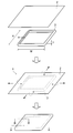
- FIG. 1 is a schematic perspective view illustrating an example of a preferred embodiment of the reflecting mirror for collecting sunlight according to the present invention from the manufacturing process.
- FIG. 2 is a schematic end view taken along the section line AA in FIG.
- the reflecting mirror 1 includes a film mirror 2 and a frame-shaped support member 3 that supports the peripheral edge of the film mirror 2.
- the support member 3 has a curved surface 3 b that is in contact with the film mirror 2 and curved in a convex shape outwardly in the horizontal direction with respect to the opening surface 3 a of the support member 3.
- 2 represents the amount of warp ( ⁇ m) of the film mirror described above
- 5 represents a point where the film mirror 2 and the support member 3 are separated from each other in a cross section perpendicular to the opening surface 3a of the support member 3 (see FIG. Hereinafter, it is also referred to as “exit point”.
- the film mirror of the reflector of the present invention has a film thickness of 0.10 to 0.30 mm
- the shape and the layer configuration are not particularly limited, and a conventionally known film mirror can be used.
- the film mirror has a film thickness of 0 because the tension of the film mirror can be easily adjusted when the peripheral portion is supported by a support member, which will be described later, and the regular reflection property is further improved and the weather resistance is also improved. It is preferably 12 to 0.27 mm, more preferably 0.15 to 0.25 mm.
- the shape of the film mirror is not particularly limited, and may be circular or polygonal, but it is easy to apply and adjust the tension of the film mirror when supporting the peripheral portion by a support member described later. Polygonal shape is preferable, and rectangular shape is more preferable.
- the size of the film mirror is not particularly limited because it can be appropriately designed according to its shape, adherend, etc., for example, the size of the rectangular film mirror (vertical width and horizontal width), from the viewpoint of tension adjustment,
- the vertical width (long side) is preferably 100 to 5000 mm
- the horizontal width (short side) is preferably 100 to 2000 mm
- the ratio of the vertical width to the horizontal width (vertical / horizontal) is 1/1 to 15/1. Is preferred.
- FIG. 3 to FIG. 6 are sectional views schematically showing examples of preferred embodiments of the film mirror included in the reflecting mirror of the present invention, and the layer structure of the film mirror is particularly limited to these drawings.
- a primer layer or an adhesive layer may be provided between the layers, and a backcoat layer may be provided on the adherend side.
- FIGS. 3 and 4 As a 1st aspect (single-sided use type) of the said film mirror, as shown, for example in FIG. 3, the film mirror 10 is the resin base material 11, the metal reflection layer 12, and the surface from the to-be-adhered body (not shown) side.
- the aspect which has in order is mentioned.
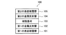
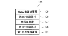
- FIGS. 5 and 6 As a 2nd aspect (double-sided use type) of the said film mirror, as shown, for example in FIG. 5, the film mirror 100 is the 1st surface coating layer 101, 1st from the to-be-adhered body (not shown) side. An aspect having the metal reflective layer 102, the resin base material 103, the second metal reflective layer 104, and the second surface coating layer 105 in this order, or as shown in FIG. 6, the film mirror 100 is attached to an adherend (not shown). A mode in which the first surface coating layer 101, the first resin base material 106, the metal reflection layer 107, the second resin base material 108, and the second surface coating layer 105 are provided in this order. .
- the resin substrate (including the first resin substrate and the second resin substrate; hereinafter the same) is not particularly limited, and examples of the constituent material thereof include polyolefin resins such as polyethylene and polypropylene; polyethylene terephthalate Polyester resins such as polyethylene naphthalate; Polycarbonate resins; Acrylic resins such as polymethyl methacrylate; Polyamide resins; Polyimide resins; Polyvinyl chloride resins; Polyphenylene sulfide resins; Polyether sulfone resins; Examples thereof include sulfide resins; polyphenylene ether resins; styrene resins; and cellulose resins such as cellulose acetate.
- the constituent materials of the first resin base material and the second resin base material used in the second mode may be the same material or different materials. Among these, from the viewpoint of the reflectance and weather resistance of the obtained film mirror, a polyester resin or an acrylic resin is preferable.
- the shape of the resin base material is not limited to a planar shape, and may be, for example, a concave shape or a convex shape.
- the thickness of the resin substrate is not particularly limited because it depends on the shape of the resin substrate. However, when the resin substrate is planar, it is usually preferably 25 to 300 ⁇ m.
- the metal reflective layer (including the first metal reflective layer and the second metal reflective layer; hereinafter the same) is not particularly limited, and examples of the constituent material (metal) include Au, Ag, Cu, Pt, Pd, In, Ga, Sn, Ge, Sb, Pb, Zn, Bi, Fe, Ni, Co, Mn, Tl, Cr, V, Ru, Rh, Ir, Al and the like can be mentioned.
- the constituent materials of the first metal reflective layer and the second metal reflective layer used in the second mode (FIG. 5) may be the same material or different materials. Among these, Ag, Al, Ni, or Cu is preferable, and Ag is more preferable from the viewpoint of the reflectance and weather resistance of the film mirror to be obtained.
- the metal which comprises a metal reflective layer is Ag
- content of Ag in a metal reflective layer is 30 mol% or more with respect to all the metals which comprise a metal reflective layer, and 50 mol% or more More preferably, it is more preferably 80 mol% or more, particularly preferably 95 mol% or more, and most preferably 100 mol%.
- the shape of the metal reflective layer is not particularly limited, and may be a layer that covers the entire main surface of the resin base material or a layer that partially covers the main surface.
- the thickness of the metal reflection layer is not particularly limited, but is preferably 50 to 500 nm, more preferably 70 to 300 nm from the viewpoint of the reflectance of the film mirror and the like.
- the method for forming the metal reflective layer is not particularly limited, and either a wet method or a dry method can be employed.
- a wet method for example, a so-called metal plating method (electroless plating or electroplating), a method known as a method of applying and heating a solution containing a metal complex compound can be mentioned.
- the dry method include a vacuum deposition method, a sputtering method, and an ion plating method.
- a primer layer is formed on a resin substrate, (ii) a plating catalyst or a precursor thereof is applied to the formed primer layer, iii) A method of plating on a primer layer provided with a plating catalyst or a precursor thereof, and the like.
- a plating catalyst or a precursor thereof is applied to the formed primer layer, iii) A method of plating on a primer layer provided with a plating catalyst or a precursor thereof, and the like.
- Step (i) is a step of forming a primer layer on the resin base material.
- the primer layer is a layer disposed between the resin base material and the metal reflective layer, and is a layer that enhances the adhesion between them.
- the primer layer is obtained by subjecting a layer containing a polymer having a functional group and a polymerizable group that interacts with the plating catalyst or its precursor to at least one of heat treatment and light irradiation treatment (hereinafter also referred to as energy application). .
- energy application hereinafter also referred to as energy application.
- the polymer used for the primer layer includes a functional group that interacts with the plating catalyst or its precursor (hereinafter also referred to as an interactive group) and a polymerizable group.
- the interactive group is a group that interacts with the plating catalyst or a precursor thereof, and plays a role of improving the adhesion between the metal reflective layer and the primer layer.
- the polymerizable group is subjected to at least one of a heat treatment and a light irradiation treatment, which will be described later, so that a crosslinking reaction proceeds and increases the strength of the primer layer, and a part of the polymerizable group reacts with the resin substrate. It plays the role which improves adhesiveness with a primer layer.
- the polymerizable group may be a functional group that can form a chemical bond between polymers or between a polymer and a resin substrate by applying energy.
- the polymerizable group include a radical polymerizable group and a cationic polymerizable group. Of these, a radical polymerizable group is preferable from the viewpoint of reactivity.
- the radical polymerizable group include a methacryloyl group, an acryloyl group, an itaconic acid ester group, a crotonic acid ester group, an isocrotonic acid ester group, a maleic acid ester group, a styryl group, a vinyl group, an acrylamide group, and a methacrylamide group. It is done.
- methacryloyl group, acryloyl group, vinyl group, styryl group, acrylamide group, and methacrylamide group are preferable, and methacryloyl group, acryloyl group, acrylamide group, methacrylamide from the viewpoint of radical polymerization reactivity and synthesis versatility.
- Group is more preferable, and from the viewpoint of alkali resistance, an acrylamide group and a methacrylamide group are more preferable.
- the type of the interactive group is not particularly limited as long as it is a group that forms an interaction with the plating catalyst or its precursor.
- ionic polar groups such as carboxyl group, sulfonic acid group, phosphoric acid group, and boronic acid group, and ether group or cyano group.
- a functional group is more preferable.
- the polymer is represented by a unit (repeating unit) represented by the following formula (1) and the following formula (2).
- the unit represented is included.
- R 10 represents a hydrogen atom or an alkyl group (for example, a methyl group, an ethyl group, etc.).
- L 2 represents a single bond or a divalent linking group.
- the divalent linking group a substituted or unsubstituted divalent aliphatic hydrocarbon group (preferably having 1 to 8 carbon atoms, for example, an alkylene group such as a methylene group, an ethylene group, or a propylene group), substituted or unsubstituted A divalent aromatic hydrocarbon group (preferably having 6 to 12 carbon atoms, such as a phenylene group), —O—, —S—, —SO 2 —, —N (R) — (R: alkyl group), And —CO—, —NH—, —COO—, —CONH—, or a combination thereof (for example, an alkyleneoxy group, an alkyleneoxycarbonyl group, an alkylenecarbonyloxy group,
- R 11 represents an interactive group.
- the definition, specific examples and preferred embodiments of the interactive group are as described above.
- the polymer may contain units kinds of interactive group represented by R 11 is represented by two or more expressions that different (1).
- a unit represented by the formula (1) in which R 11 is an ionic polar group and a unit represented by the formula (1) in which R 11 is a non-dissociable functional group are contained in the polymer. May be.
- R 12 to R 15 each independently represents a hydrogen atom or a substituted or unsubstituted alkyl group.
- R 12 to R 15 are a substituted or unsubstituted alkyl group
- an alkyl group having 1 to 6 carbon atoms is preferable, and an alkyl group having 1 to 4 carbon atoms is more preferable.
- examples of the unsubstituted alkyl group include a methyl group, an ethyl group, a propyl group, and a butyl group
- examples of the substituted alkyl group include a methoxy group, a hydroxy group, and a halogen atom (for example, a chlorine atom).
- a bromine atom, a fluorine atom) and the like and a methyl group, an ethyl group, a propyl group, and a butyl group.
- R 12 is preferably a hydrogen atom, a methyl group, or a methyl group substituted with a hydroxy group or a bromine atom.
- R 13 is preferably a hydrogen atom, a methyl group, or a methyl group substituted with a hydroxy group or a bromine atom.
- R 14 is preferably a hydrogen atom.
- R 15 is preferably a hydrogen atom.
- L 3 represents a single bond or a divalent linking group. Specific examples and preferred embodiments of the divalent linking group are the same as L 2 in the above formula (1).
- a copolymer comprising a unit represented by the following formula (A), a unit represented by the following formula (B), and a unit represented by the following formula (C)
- a copolymer comprising a unit represented by the following formula (A) and a unit represented by the following formula (B), a unit represented by the following formula (A) and a unit represented by the following formula (C); And the like, and the like.
- R 21 to R 26 each independently represents a hydrogen atom or a substituted or unsubstituted alkyl group having 1 to 4 carbon atoms.
- X, Y, Z, and U each independently represent a single bond or a divalent linking group.
- L 4 , L 5 and L 6 each independently represents a single bond or a divalent linking group.
- W represents an interactive group composed of a non-dissociable functional group.
- V represents an interactive group composed of an ionic polar group. Specific examples and preferred embodiments of the divalent linking group are the same as L 2 in the above formula (1).
- Y and Z are preferably each independently an ester group, an amide group, or a phenylene group (—C 6 H 4 —).
- L 4 is preferably a substituted or unsubstituted divalent organic group (particularly a hydrocarbon group) having 1 to 10 carbon atoms.
- W is preferably a cyano group or an ether group.
- X and L 5 is preferably either a single bond.
- V is preferably a carboxylic acid group
- V is a carboxylic acid group
- L 6 is a 4-membered to 8-membered ring at the portion where V is connected to V.
- V is a carboxylic acid group and the chain length of L 6 is 6 to 18 atoms is also preferable.
- V is a carboxylic acid group and U and L 6 are single bonds.
- an embodiment in which V is a carboxylic acid group and both U and L 6 are single bonds is most preferable.
- the content of the units represented by the formulas (A) to (C) is preferably in the following range. That is, in the case of a copolymer including a unit represented by the formula (A), a unit represented by the formula (B), and a unit represented by the formula (C), the copolymer is represented by the formula (A).
- Unit: Unit represented by formula (B): Unit represented by formula (C) 5-50 mol%: 5-40 mol%: 20-70 mol% is preferable, 10-40 mol%: 10-35 mol %: More preferably 20 to 60 mol%.
- a unit represented by the formula (A): a unit represented by the formula (C) 5 to 50 mol%: 50 to 95 mol% is preferable, and 10 to 40 mol%: 60 to 90 mol% is more preferable.
- a unit represented by the formula (A): a unit represented by the formula (C) 5 to 50 mol%: 50 to 95 mol% is preferable, and 10 to 40 mol%: 60 to 90 mol% is more preferable.
- the method for forming the layer containing the polymer is not particularly limited, and a known method can be adopted.
- the layer forming composition containing the said polymer is apply
- the layer containing the polymer is subjected to at least one of heat treatment and light irradiation treatment.
- the treatment carried out on the layer containing the polymer may be carried out either by heat treatment or light irradiation treatment, or by both. Moreover, when performing both processing, you may implement by a separate process and may implement simultaneously.
- the polymerizable group is activated, the reaction proceeds between the polymerizable groups and between the polymerizable group and the resin base material, and a primer layer adhered to the resin base material is formed.
- the optimum conditions for the heat treatment are selected according to the type of polymer used. Among them, the crosslinking density of the primer layer is increased, and the weather resistance and flexibility of the film mirror are enhanced.
- the treatment is preferably performed at (preferably 80 to 120 ° C.) for 0.1 to 3 hours (preferably 0.5 to 2 hours).
- Optimum conditions are selected for the light irradiation treatment depending on the type of polymer used.
- the exposure density is increased in that the crosslinking density of the primer layer increases and the weather resistance and flexibility of the film mirror increases. preferably 10 ⁇ 8000mJ / cm 2 is more preferably 100 ⁇ 3000mJ / cm 2.
- the exposure wavelength is preferably 200 to 300 nm.
- the light source used for exposure is not particularly limited, and examples thereof include a mercury lamp, a metal halide lamp, a xenon lamp, a chemical lamp, and a carbon arc lamp.
- Examples of radiation include electron beams, X-rays, ion beams, and far infrared rays.
- the unreacted polymer may be appropriately removed from the composition after the heat treatment or light irradiation treatment.
- the removal method include a method using a solvent.
- a solvent that dissolves a polymer or an alkali-soluble polymer an alkaline developer (sodium carbonate, sodium bicarbonate, aqueous ammonia, aqueous sodium hydroxide) Etc. can be removed.
- the thickness of the primer layer is not particularly limited, but is preferably 0.05 to 10 ⁇ m, more preferably 0.3 to 5 ⁇ m, in terms of excellent weather resistance and flexibility of the film mirror.
- a catalyst provision process is a process of providing a plating catalyst or its precursor to a primer layer.
- the plating catalyst or its precursor is adsorbed on the interactive group in the primer layer.
- the plating catalyst or a precursor thereof include those that function as a plating catalyst or an electrode in “step (iii): plating step” described later. Therefore, the plating catalyst or its precursor is determined by the type of plating in the plating process.
- the plating catalyst for example, electroless plating catalyst used or its precursor is explained in full detail.
- the electroless plating catalyst is preferably one that can be an active nucleus during electroless plating.
- Examples thereof include metals having catalytic ability for autocatalytic reduction reaction (known as metals capable of electroless plating having a lower ionization tendency than Ni), and specifically include Pd, Ag, Cu, Ni, Al, Fe, and the like. , Co and the like. Of these, Pd or Ag is preferable because of its high catalytic ability.
- the electroless plating catalyst precursor those capable of becoming an electroless plating catalyst by a chemical reaction are preferable.
- the metal ions of the metals mentioned as the electroless plating catalyst are used.
- the metal ion that is an electroless plating catalyst precursor becomes a zero-valent metal that is an electroless plating catalyst by a reduction reaction.
- the electroless plating catalyst may be converted into a zero-valent metal by a separate reduction reaction.
- the plating catalyst precursor may be immersed in an electroless plating bath and changed to a metal (electroless plating catalyst) by a reducing agent in the electroless plating bath.
- the metal ion which is an electroless-plating catalyst precursor is provided to a primer layer using a metal salt.
- the metal salt used is not particularly limited as long as it is dissolved in a suitable solvent and dissociated into a metal ion and a base (anion), and M (NO 3 ) n , MCl n , M 2 / n (SO 4 ), M 3 / n (PO 4 ) Pd (OAc) n (M represents an n-valent metal atom), and the like.
- a metal ion the thing which said metal salt dissociated can be used suitably. Specific examples include Ag ions, Cu ions, Al ions, Ni ions, Co ions, Fe ions, and Pd ions. Among them, those capable of multidentate coordination are preferable, and Ag ions, Cu ions, and Pd ions are particularly preferable in terms of the number of types of functional groups capable of coordination and catalytic ability.
- the catalyst activation liquid often contains a reducing agent capable of reducing the electroless plating catalyst precursor (mainly metal ions) to a zero-valent metal and a pH adjusting agent for activating the reducing agent.
- the concentration of the reducing agent with respect to the entire liquid is preferably 0.1 to 10% by mass.
- the reducing agent it is possible to use a boron-based reducing agent such as sodium borohydride or dimethylamine borane, or a reducing agent such as formaldehyde or hypophosphorous acid. In particular, reduction with an aqueous alkaline solution containing formaldehyde is preferred.
- the catalyst used in order to perform electroplating directly, without performing electroless plating as a plating catalyst.
- a catalyst include zero-valent metals, and more specifically, Pd, Ag, Cu, Ni, Al, Fe, Co, and the like.
- Pd, Ag, and Cu are particularly preferable from the viewpoints of the adsorptive (adhesive) property to interactive groups and the high catalytic ability.
- a solution containing these for example, a dispersion in which a metal is dispersed in an appropriate dispersion medium, or a metal that has been dissociated by dissolving a metal salt in an appropriate solvent.
- a solution containing ions is prepared, and the dispersion or solution is applied onto the primer layer, or the resin substrate on which the primer layer is formed is immersed in the dispersion or solution.
- a plating process is a process of forming a metal reflective layer by performing a plating process with respect to the primer layer to which the plating catalyst or its precursor was provided.
- the type of plating performed in this step includes electroless plating and electroplating, and can be appropriately selected depending on the function of the plating catalyst applied to the primer layer or the precursor thereof in the catalyst application step. That is, in this step, electroplating may be performed on the primer layer provided with the plating catalyst or its precursor, or electroless plating may be performed.
- the plating process suitably performed in this process will be described.
- Electroless plating refers to an operation of depositing a metal by a chemical reaction using a solution in which metal ions to be deposited as a plating are dissolved. Electroless plating is performed, for example, by immersing a resin base material provided with a primer layer provided with an electroless plating catalyst in water after removing excess electroless plating catalyst (metal) and then immersing it in an electroless plating bath. .
- a known electroless plating bath can be used as the electroless plating bath used.
- the substrate is It is preferable to immerse in an electroless plating bath after washing to remove excess precursors (such as metal salts). In this case, reduction of the plating catalyst precursor and subsequent electroless plating are performed in the electroless plating bath.
- a known electroless plating bath can be used as described above.
- electroplating can be performed on the primer layer provided with the plating catalyst or its precursor.
- a conventionally known method can be used as the electroplating method in the present invention.
- a metal used for the electroplating of this process copper, chromium, lead, nickel, gold, silver, tin, zinc, etc. are mentioned, and from the reason that the reflectance of the obtained film mirror is further improved, silver is used. preferable.
- the formed plating film may be used as an electrode, and electroplating may be further performed.
- the silver compounds used for plating include silver nitrate, silver acetate, silver sulfate, silver carbonate, silver methanesulfonate, ammonia silver, silver cyanide, silver thiocyanate, silver chloride, silver bromide, silver chromate, and chloranilic acid.
- Examples thereof include silver, silver salicylate, silver diethyldithiocarbamate, silver diethyldithiocarbamate, and silver p-toluenesulfonate.
- silver methanesulfonate is preferable because the reflectance of the obtained film mirror is further improved.
- the surface coating layer (including the first surface coating layer and the second surface coating layer, the same applies hereinafter) is not particularly limited, and the constituent material only needs to have transparency to transmit light. .
- resin, glass, ceramic and the like can be mentioned, and among them, resin is preferable in terms of excellent flexibility.
- the resin examples include urethane (meth) acrylate resin, polyester (meth) acrylate resin, silicone (meth) acrylate resin, epoxy (meth) acrylate resin, and other photocurable resins; phenol resin, urea resin (urea resin), Thermosetting resins such as phenoxy resin, silicone resin, polyimide resin, diallyl phthalate resin, furan resin, bismaleimide resin, cyanate resin; thermoplastic resins such as phenoxy resin, polyether sulfone, polysulfone, polyphenylene sulfone; It is done.
- the constituent materials of the first surface coating layer and the second surface coating layer used in the second mode may be the same material or different materials.
- the thickness of the surface coating layer is not particularly limited, but is preferably 10 to 200 ⁇ m, more preferably 25 to 100 ⁇ m, from the viewpoint of better weather resistance and flexibility of the film mirror.
- the method for forming the surface coating layer is not particularly limited.
- a method in which a predetermined resin substrate is bonded onto the metal reflective layer, or a curable composition containing the above-described photocurable resin or thermosetting resin is used as a metal reflective layer.
- the method include photocuring by ultraviolet irradiation and heat curing by heating after coating on the layer.
- the constituent material of the arbitrary primer layer is not particularly limited as long as it can improve the adhesion between each layer. Specific examples thereof include polyester resin, urethane resin, acrylic resin, urethane acrylic resin, polyamide resin. And resin materials such as cycloolefin polymer resins. Further, the thickness of the primer layer is not particularly limited, and is preferably 0.1 to 50 ⁇ m, and more preferably 1 to 30 ⁇ m. The method for forming the primer layer is not particularly limited.
- urethane acrylic resin for example, EBECRYL8402 manufactured by Daicel-Cytec
- a photopolymerization initiator for example, Ciba Specialty
- a mixed solution with Irgacure 184 manufactured by Chemicals, etc. is applied to the surface of the resin substrate and then photocured by ultraviolet irradiation.
- the constituent material of any adhesive layer is not particularly limited as long as it satisfies adhesion and smoothness. Specific examples thereof include polyester resins, acrylate resins, melamine resins, epoxy resins, polyamide resins. Examples thereof include resins, vinyl chloride resins, vinyl chloride vinyl acetate copolymer resins, and the like. These may be used alone or in combination of two or more.
- the thickness of the adhesive layer is not particularly limited, and is preferably from 0.01 to 5 ⁇ m, more preferably from 0.1 to 2 ⁇ m, from the viewpoints of adhesion, smoothness, reflectance, and the like. Further, the method for forming the adhesive layer is not particularly limited. For example, gravure coating method, reverse coating method, die coating method, blade coater, roll coater, air knife coater, screen coater, bar coater, curtain coater, etc. Can be used.
- the material for forming the optional backcoat layer is not particularly limited, and examples thereof include urethane resins and resins contained in the surface coating layer described above. Further, the thickness of the backcoat layer is not particularly limited, and is preferably 0.5 to 50 ⁇ m, more preferably 1 to 30 ⁇ m. Further, the method for forming the backcoat layer is not particularly limited. For example, when the above-described photocurable resin or thermosetting resin is used as the backcoat layer, the curable composition containing these resins is used as the upper resin group. Examples of the method include photocuring by ultraviolet irradiation and heat curing by heating after coating on the back surface of the material.
- the support member included in the reflecting mirror of the present invention is a frame-shaped support member that supports the peripheral portion of the film mirror described above, and is in contact with the film mirror and horizontally outward with respect to the opening surface of the support member. It is a member that has a curved surface that is convexly curved and has a curvature radius of 8 mm or more.
- the shape of the cross section parallel to the opening surface of the support member is not particularly limited. Like the film mirror described above, the shape may be circular or polygonal, and it is easy to apply and adjust the tension of the film mirror. Therefore, the shape is preferably polygonal, and more preferably rectangular (quadrangle).
- the shape in the cross section perpendicular to the opening surface of the support member (hereinafter also referred to as “vertical cross section shape”) is convex outward in the horizontal direction with respect to the opening surface of the support member at the portion in contact with the film mirror. It has a curved surface that is curved and has a radius of curvature of 8 mm or more.
- the support member 3 has a curved surface 3 b that is curved in a convex shape outwardly in the horizontal direction with respect to the opening surface 3 a of the support member 3 at a portion in contact with the film mirror 2.
- the radius of curvature of the curved surface 3b is 8 mm or more.
- the film thickness (0.10 to 0.30 mm) of the above-described film mirror and the curvature of the support member is preferably 80 or more, more preferably 90 or more, and still more preferably 90 to 260.
- the curvature radius of the curved surface of the support member is preferably 15 mm or more, because the amount of warpage of the film mirror becomes smaller and the condensing characteristic of the reflecting mirror becomes better. It is preferably 30 mm.
- the film mirror and the support member are separated from each other in the cross section perpendicular to the opening surface of the support member (see FIGS.
- the angle (hereinafter referred to as “outgoing angle”) formed between the tangent line of the support member and the opening surface of the support member at a point indicated by an emission point 5 in FIG. 7 described later is 0 ° or more and 20 ° or less. It is preferable that the angle is 5 to 15 °.
- each type of cross-sectional view shown in FIGS. 7A to 7F is an example of a schematic cross-sectional view taken along the section line BB in FIG. It is not limited to this type.
- the vertical cross-sectional shape of the support member is not particularly limited as long as it has the above-described curved surface, and a curved portion and a rectangular portion (rectangular shape) as shown in FIG. ), A circular shape including a curved surface as shown in (B) and (C), a curved portion and a rectangular portion as shown in (D) to (F) ( The shape which consists of trapezoid) may be sufficient.
- 7A to 7C, all of FIGS. 7A to 7C are examples in which the emission angle is 0 °
- FIG. 7E shows an example in which the emission angle ⁇ is 15 °
- FIG. 7F shows an example in which the emission angle ⁇ is 30 °.
- the material constituting the support member is not particularly limited. Specific examples thereof include stainless steel (SUS), aluminum, aluminum alloy, titanium and other metal materials; carbon fiber reinforced plastic, polyether ether ketone (PEEK), polyphenylene sulfide. Resin materials such as (PPS); and the like. Among these, since most of the adherends are metal materials, the metal materials are preferable from the viewpoint of joining with the adherends, and stainless steel or aluminum is more preferable.
- the thickness of the support member is not particularly limited, and is preferably 1 to 10 mm, more preferably 2 to 5 mm.
- the width (FIG. 1—reference symbol w) of the constituent member (frame member) of the support member is not particularly limited, but is preferably 10 to 50 mm, and more preferably 15 to 30 mm.
- the overall vertical width (long side) of the support member (Fig. 1-symbol H) is preferably 100 to 5000 mm, and the lateral width (short side) (Fig. 1-symbol W) is 100 to 2000 mm.
- the ratio of the vertical width to the horizontal width is preferably 1/1 to 10/1.
- the method for producing the reflecting mirror of the present invention is not particularly limited.
- a film mirror 2 having a size larger than the size of the support member 3 and the support member 3 are overlapped to form the film mirror 2.
- the film mirror 2 can be produced by folding the end of the film mirror 2 in the direction of the broken line arrow and joining it to the support member 3 with tension applied in the direction of the black arrow.
- an adhesive tape or the like is used to some extent on a temporary fixing frame material (temporary frame material) having a size (H ⁇ W) larger than that of the support member and a thickness (t) being smaller.
- the support member coated with the adhesive is stuck vertically to the temporarily fixed film mirror, and the support member is pushed into the frame of the temporary frame material, thereby A reflecting mirror in which the peripheral portion of the mirror is bonded (adhered) to the support member can be manufactured.
- the method of joining the end of the film mirror and the support member is not particularly limited, and examples thereof include a method of bonding using an adhesive or an adhesive, a method of fixing both using a clip, and the like. .
- this invention has at least two through-holes utilized for joining to adherends, such as a solar reflector main body (sunlight tracking system), in the joining area
- adherends such as a solar reflector main body (sunlight tracking system)
- Example 1 (Formation of primer layer) On a PET substrate (thickness: 50 ⁇ m, manufactured by FUJIFILM Corporation), a solution containing an acrylic polymer represented by the formula (3) was applied by spin coating so as to have a thickness of 500 nm, and 5 ° C. at 80 ° C. The film was dried for a while to obtain a coating film.
- the numerical value in Formula (3) represents the ratio (mol%) of each unit.
- the synthesis method of the acrylic polymer represented by the formula (3) is as follows. 1 L of ethyl acetate and 159 g of 2-aminoethanol were placed in a 2 L three-necked flask and cooled in an ice bath. Thereto, 150 g of 2-bromoisobutyric acid bromide was added dropwise while adjusting the internal temperature to 20 ° C. or less. Thereafter, the internal temperature was raised to room temperature (25 ° C.) and reacted for 2 hours. After completion of the reaction, 300 mL of distilled water was added to stop the reaction.
- the ethyl acetate layer was washed four times with 300 mL of distilled water, dried over magnesium sulfate, and 80 g of raw material A was obtained by distilling off ethyl acetate.
- 47.4 g of raw material A, 22 g of pyridine, and 150 mL of ethyl acetate were placed in a 500 mL three-necked flask and cooled in an ice bath.
- 25 g of acrylic acid chloride was added dropwise while adjusting the internal temperature to 20 ° C. or lower. Then, it was raised to room temperature and reacted for 3 hours. After completion of the reaction, 300 mL of distilled water was added to stop the reaction.
- the preparation method of the solution containing the acrylic polymer represented by Formula (3) is as follows.
- the acrylic polymer represented by the formula (3) (7 parts by mass), 1-methoxy-2-propanol (74 parts by mass) and water (19 parts by mass) were mixed.
- a polymerization initiator (Esacure KTO-46, manufactured by Lamberdy) (0.35 parts by mass) was added and mixed by stirring to obtain a solution containing an acrylic polymer represented by formula (3).
- the coating film is irradiated with a cumulative exposure amount of 1000 mJ / cm 2 at a wavelength of 254 nm, A primer layer (thickness: 500 nm) was formed. Development was performed to remove unreacted polymer from the primer layer. Specifically, the PET support with a primer layer was immersed in a 1 wt% aqueous sodium hydrogen carbonate solution for 5 minutes. Thereafter, it was washed with pure water.
- the PET support with primer layer was immersed in a 1 wt% aqueous silver nitrate solution for 5 minutes and then washed with pure water to obtain a PET support with primer layer to which an electroless plating catalyst precursor (silver ions) was applied. Obtained. Further, the obtained resin substrate with a primer layer was immersed in an alkaline aqueous solution (pH 12.5) (corresponding to a reducing agent) containing 0.14 wt% NaOH and 0.25 wt% formalin for 1 minute, and then purified. By washing with water, a PET support with a primer layer provided with a reduced metal (silver) was obtained.
- an electroless plating catalyst precursor silver ions
- the following electroplating process was performed on the primer layer to which the reduced metal (silver) was applied, and a metal (silver) reflective layer having a thickness of 200 nm was formed on the primer layer.
- a metal (silver) reflective layer having a thickness of 200 nm was formed on the primer layer.
- Dyne Silver Bright PL50 manufactured by Daiwa Kasei Co., Ltd.
- the pH was adjusted to 9.0 with 8M potassium hydroxide.
- a PET support with a primer layer having a reduced metal surface was immersed in an electroplating solution, plated at 0.5 A / dm 2 for 15 seconds, and then washed by pouring with pure water for 1 minute.
- the produced film mirror is temporarily fixed using a pressure-sensitive adhesive tape on a temporary fixing frame material (size: 700 mm ⁇ 700 mm square, width: 25 mm, thickness: 5 mm).
- a frame-shaped support member made of aluminum (A5052) (size: 500 mm ⁇ 500 mm square, width: 25 mm, thickness: 10 mm, vertical sectional shape: FIG. 7A, emission angle: 0 °, radius of curvature: 9 mm)
- An adhesive (Fine Tuck, manufactured by DIC) was applied to the surface of the frame.
- the adhesive application surface of the support member is bonded vertically to the film mirror temporarily fixed to the temporarily fixing frame material (temporary frame material), and the support member is further pushed into the frame of the temporary frame material.
- a reflecting mirror was produced.
- Table 1 the size of the supporting member used, the vertical cross-sectional shape, the emission angle and the radius of curvature are shown, and the ratio of the film mirror film thickness to the supporting member curvature radius (curvature radius / film thickness), And the joining method of a film mirror and a supporting member is shown.
- “ ⁇ 500 mm” in size represents 500 mm ⁇ 500 mm square.
- Example 2 A reflecting mirror was produced in the same manner as in Example 1 except that the thickness of the PET substrate was changed to 150 ⁇ m and the film mirror thickness was changed to 0.21 mm.
- Example 3 A reflecting mirror was produced in the same manner as in Example 1 except that the thickness of the PET substrate was changed to 220 ⁇ m and the film mirror thickness was changed to 0.28 mm.
- Example 4 A reflective mirror was produced in the same manner as in Example 2 except that the metal reflective layer formed by the method shown below was used without forming the primer layer.
- a sputtering method PVD is used to alternately form TiO 2 of 65 nm and SiO 2 of 110 nm, 8 layers of TiO 2 and 7 of SiO 2.
- a metallic reflective layer was formed.
- Example 5> Instead of aluminum (A5052) frame-shaped support member (size: 500 mm ⁇ 500 mm square, width: 25 mm, thickness: 10 mm, vertical cross-sectional shape: FIG. 7A, emission angle: 0 °, radius of curvature: 9 mm) A stainless steel (SUS304) frame-shaped support member (size: 500 mm ⁇ 500 mm, width: 25 mm, thickness: 10 mm, vertical cross-sectional shape: FIG. 7A, emission angle: 0 °, curvature radius: 9 mm) A reflecting mirror was produced in the same manner as in Example 2 except that it was used.
- a stainless steel (SUS304) frame-shaped support member size: 500 mm ⁇ 500 mm, width: 25 mm, thickness: 10 mm, vertical cross-sectional shape: FIG. 7A, emission angle: 0 °, curvature radius: 9 mm
- a reflecting mirror was produced in the same manner as in Example 2 except that it was used.
- Example 6> Instead of aluminum (A5052) frame-shaped support member (size: 500 mm ⁇ 500 mm square, width: 25 mm, thickness: 10 mm, vertical cross-sectional shape: FIG. 7A, emission angle: 0 °, radius of curvature: 9 mm)
- Aluminum (A5052) frame-shaped support member (size: 500 mm ⁇ 500 mm square, width: 25 mm, thickness: 10 mm, vertical cross-sectional shape: FIG. 7B, emission angle: 0 °, radius of curvature: 18 mm)
- a reflecting mirror was manufactured in the same manner as in Example 1 except that was used.
- Example 7 A reflecting mirror was produced in the same manner as in Example 6 except that the thickness of the PET substrate was changed to 150 ⁇ m and the film mirror thickness was changed to 0.21 mm.
- Example 8> A reflecting mirror was produced in the same manner as in Example 6 except that the thickness of the PET substrate was changed to 220 ⁇ m and the film mirror thickness was changed to 0.28 mm.
- Example 9 Instead of aluminum (A5052) frame-shaped support member (size: 500 mm ⁇ 500 mm square, width: 25 mm, thickness: 10 mm, vertical cross-sectional shape: FIG. 7A, emission angle: 0 °, radius of curvature: 9 mm)
- Aluminum (A5052) frame-shaped support member (size: 500 mm ⁇ 500 mm square, width: 25 mm, thickness: 10 mm, vertical cross-sectional shape: FIG. 7C, emission angle: 0 °, curvature radius: 28 mm)
- a reflecting mirror was manufactured in the same manner as in Example 1 except that was used.
- Example 10> A reflecting mirror was produced in the same manner as in Example 9, except that the thickness of the PET substrate was changed to 150 ⁇ m and the film mirror thickness was changed to 0.21 mm.
- Example 11 A reflecting mirror was produced in the same manner as in Example 9 except that the thickness of the PET substrate was changed to 220 ⁇ m and the film mirror thickness was changed to 0.28 mm. A reflector was manufactured.
- Example 12 Instead of aluminum (A5052) frame-shaped support member (size: 500 mm ⁇ 500 mm square, width: 25 mm, thickness: 10 mm, vertical cross-sectional shape: FIG. 7A, emission angle: 0 °, radius of curvature: 9 mm)
- Aluminum (A5052) frame-shaped support member (size: 500 mm ⁇ 500 mm square, width: 25 mm, thickness: 10 mm, vertical cross-sectional shape: FIG. 7D, emission angle: 10 °, radius of curvature: 18 mm)
- a reflecting mirror was produced in the same manner as in Example 2 except that was used.
- Example 13 Instead of aluminum (A5052) frame-shaped support member (size: 500 mm ⁇ 500 mm square, width: 25 mm, thickness: 10 mm, vertical cross-sectional shape: FIG. 7A, emission angle: 0 °, radius of curvature: 9 mm)
- Aluminum (A5052) frame-shaped support member (size: 500 mm ⁇ 500 mm square, width: 25 mm, thickness: 10 mm, vertical cross-sectional shape: FIG. 7 (E), emission angle: 17 °, curvature radius: 18 mm)
- a reflecting mirror was produced in the same manner as in Example 2 except that was used.
- Example 14> Instead of aluminum (A5052) frame-shaped support member (size: 500 mm ⁇ 500 mm square, width: 25 mm, thickness: 10 mm, vertical cross-sectional shape: FIG. 7A, emission angle: 0 °, radius of curvature: 9 mm)
- Aluminum (A5052) frame-shaped support member (size: 500 mm ⁇ 500 mm square, width: 25 mm, thickness: 10 mm, vertical cross-sectional shape: FIG. 7 (F), emission angle: 30 °, radius of curvature: 18 mm)
- a reflecting mirror was produced in the same manner as in Example 2 except that was used.
- Example 1 A reflecting mirror was produced in the same manner as in Example 1 except that the thickness of the PET substrate was changed to 350 ⁇ m and the film mirror thickness was changed to 0.41 mm.
- a pressure-sensitive adhesive (Fine Tuck, manufactured by DIC) was applied to the resin substrate side of the film mirror produced in Example 2, and bonded to the adherend (SUS304).
- Warpage amount is less than 20 ⁇ m
- ⁇ Specularity (Diffusion component ratio)> The specular reflectivity of each of the produced reflectors was evaluated by calculating the energy ratio of the diffusion component to the total reflected light. Specifically, light is emitted from the LED for light source onto the reflecting mirror, the reflected light is received as an image by the CCD image sensor through the lens, and the total area of the regular reflection component and the diffusion component in the obtained image is It calculated from the ratio which the diffusion component accounts for. Moreover, it evaluated according to the following criteria. AA: diffusion component ratio is less than 2.0% A: diffusion component ratio is 2.0% or more and less than 5.0% B: diffusion component ratio is 5.0% or more and less than 10.0% C: diffusion component ratio is 10 0.0% or more
- ⁇ Heat resistance (temperature cycle)> The temperature cycle of each of the prepared mirrors is the surface of the film mirror, such as wrinkles, undulations, peeling, etc. after 3000 times of standing at ⁇ 40 ° C. for 30 minutes and standing at 65 ° C. for 30 minutes. State faults were observed and evaluated according to the following criteria. AA: Even if the number of cycles is doubled to 6000 times, no planar failure occurs. A: No surface failure occurs. B: Slight surface failure occurs. C: Peeling between the film mirror and the support member occurs in a partial region. D: Planar failure occurs remarkably.
- each of the reflecting mirrors having a film mirror having a predetermined film thickness and a support member having a curved surface with a specific radius of curvature at a predetermined position is excellent in heat resistance and the amount of warping of the film mirror.
- the specular reflection property and the light collecting property were found to be excellent (Examples 1 to 14).
- the ratio (curvature radius / film thickness) of the film mirror thickness to the curvature radius of the curved surface of the support member is 80 or more
- the amount of warpage of the film mirror is It became smaller and the condensing characteristic of the reflecting mirror was found to be better.
- Examples 6 to 14 in which the radius of curvature of the curved surface of the support member is 15 mm or more it has been found that the amount of warpage of the film mirror becomes smaller and the light collecting characteristics of the reflecting mirror become better.
Landscapes
- Engineering & Computer Science (AREA)
- Physics & Mathematics (AREA)
- Life Sciences & Earth Sciences (AREA)
- Sustainable Development (AREA)
- Chemical & Material Sciences (AREA)
- Thermal Sciences (AREA)
- Sustainable Energy (AREA)
- Combustion & Propulsion (AREA)
- Mechanical Engineering (AREA)
- General Engineering & Computer Science (AREA)
- Astronomy & Astrophysics (AREA)
- General Physics & Mathematics (AREA)
- Optics & Photonics (AREA)
- Optical Elements Other Than Lenses (AREA)
Abstract
本発明は、耐熱性に優れ、かつ、フィルムミラーの反り量が小さく、正反射性および集光特性に優れる太陽光集光用反射鏡を提供することを目的とする。本発明の太陽光集光用反射鏡は、フィルムミラーと、フィルムミラーの周縁部を支持する枠形状の支持部材とを有する、太陽光集光用反射鏡であって、 フィルムミラーの膜厚が、0.10~0.30mmであり、 支持部材が、フィルムミラーと接し、かつ、支持部材の開口面に対して水平方向外向きに凸状に湾曲した湾曲面を有し、 湾曲面の曲率半径が8mm以上である太陽光集光用反射鏡である。
Description
本発明は、太陽光集光用フィルムミラーを用いた太陽光集光用反射鏡に関する。
太陽光の反射装置には、太陽光による紫外線や熱、風雨、砂塵等に晒されるため、従来、ガラス製ミラーが用いられてきた。
しかしながら、ガラス製ミラーを用いる場合、輸送時に破損する問題や、ミラーを設置する架台に高い強度が要求されるため建設費がかさむといった問題があった。
このような問題を解決するために、近年では、ガラス製ミラーを樹脂製反射シート(フィルムミラー)に置き換えることが提案されている。
しかしながら、ガラス製ミラーを用いる場合、輸送時に破損する問題や、ミラーを設置する架台に高い強度が要求されるため建設費がかさむといった問題があった。
このような問題を解決するために、近年では、ガラス製ミラーを樹脂製反射シート(フィルムミラー)に置き換えることが提案されている。
例えば、特許文献1には、「Al,Ag等の反射率の大きい金属薄膜をプラスチックフィルム上に蒸着、スパッタリング、貼付け等で形成した反射フィルムをリング状又はディスク状部材に取付けたことを特徴とする反射鏡。」が記載されており(特許請求の範囲(1)等参照)、リング状部材がフィルムに張力付加および張力付加状態で固定する部材であることが記載されている(第2頁右下欄第16行~20行)。
本発明者は、特許文献1に記載された反射鏡について検討したところ、宇宙用途以外の使用環境によっては、耐熱性(温度サイクル)が劣り、また、フィルムの反り量が大きくなるため、これらに伴う正反射性や集光特性が劣る場合があることを明らかとした。
そこで、本発明は、耐熱性に優れ、かつ、フィルムミラーの反り量が小さく、正反射性および集光特性に優れる太陽光集光用反射鏡を提供することを課題とする。
本発明者は、上記課題を達成すべく鋭意研究した結果、所定の膜厚を有するフィルムミラーと特定の曲率半径の湾曲面を所定の位置に有する支持部材とを具備する太陽光集光用反射鏡が、耐熱性に優れ、かつ、フィルムミラーの反り量が小さく、正反射性および集光特性に優れることを見出し、本発明を完成させた。
すなわち、本発明は、以下の(1)~(8)を提供する。
すなわち、本発明は、以下の(1)~(8)を提供する。
(1) フィルムミラーと、フィルムミラーの周縁部を支持する枠形状の支持部材とを有する、太陽光集光用反射鏡であって、
フィルムミラーの膜厚が、0.10~0.30mmであり、
支持部材が、フィルムミラーと接し、かつ、支持部材の開口面に対して水平方向外向きに凸状に湾曲した湾曲面を有し、
湾曲面の曲率半径が8mm以上である太陽光集光用反射鏡。
(2) フィルムミラーの膜厚と支持部材における湾曲面の曲率半径との比率(曲率半径/膜厚)が、80以上である(1)に記載の太陽光集光用反射鏡。
(3) 支持部材における湾曲面の曲率半径が、15mm以上である(1)または(2)に記載の太陽光集光用反射鏡。
(4) 支持部材の開口面と垂直な断面においてフィルムミラーと支持部材とが離れる点における支持部材の接線と、支持部材の開口面とのなす角が、0°以上20°以下である(1)~(3)のいずれかに記載の太陽光集光用反射鏡。
(5) フィルムミラーが、樹脂基材、金属反射層および表面被覆層を有する多角形状のフィルムミラーである(1)~(4)のいずれかに記載の太陽光集光用反射鏡。
(6) フィルムミラーの形状が、矩形状である(1)~(5)のいずれかに記載の太陽光集光用反射鏡。
フィルムミラーの膜厚が、0.10~0.30mmであり、
支持部材が、フィルムミラーと接し、かつ、支持部材の開口面に対して水平方向外向きに凸状に湾曲した湾曲面を有し、
湾曲面の曲率半径が8mm以上である太陽光集光用反射鏡。
(2) フィルムミラーの膜厚と支持部材における湾曲面の曲率半径との比率(曲率半径/膜厚)が、80以上である(1)に記載の太陽光集光用反射鏡。
(3) 支持部材における湾曲面の曲率半径が、15mm以上である(1)または(2)に記載の太陽光集光用反射鏡。
(4) 支持部材の開口面と垂直な断面においてフィルムミラーと支持部材とが離れる点における支持部材の接線と、支持部材の開口面とのなす角が、0°以上20°以下である(1)~(3)のいずれかに記載の太陽光集光用反射鏡。
(5) フィルムミラーが、樹脂基材、金属反射層および表面被覆層を有する多角形状のフィルムミラーである(1)~(4)のいずれかに記載の太陽光集光用反射鏡。
(6) フィルムミラーの形状が、矩形状である(1)~(5)のいずれかに記載の太陽光集光用反射鏡。
(7) フィルムミラーが、第1の表面被覆層、第1の金属反射層、樹脂基材、第2の金属反射層および第2の表面被覆層をこの順に有するフィルムミラーである(1)~(6)のいずれかに記載の太陽光集光用反射鏡。
(8) フィルムミラーが、第1の表面被覆層、第1の樹脂基材、金属反射層、第2の樹脂基材および第2の表面被覆層をこの順に有するフィルムミラーである(1)~(6)のいずれかに記載の太陽光集光用反射鏡。
(8) フィルムミラーが、第1の表面被覆層、第1の樹脂基材、金属反射層、第2の樹脂基材および第2の表面被覆層をこの順に有するフィルムミラーである(1)~(6)のいずれかに記載の太陽光集光用反射鏡。
以下に説明するように、本発明によれば、耐熱性に優れ、かつ、フィルムミラーの反り量が小さく、正反射性および集光特性に優れる太陽光集光用反射鏡を提供することができる。
[太陽光集光用反射鏡]
本発明の太陽光集光用反射鏡(以下、「本発明の反射鏡」と略す。)は、フィルムミラーと、フィルムミラーの周縁部を支持する枠形状の支持部材とを有する、太陽光集光用反射鏡であって、フィルムミラーの膜厚が、0.10~0.30mmであり、支持部材が、フィルムミラーと接し、かつ、支持部材の開口面に対して水平方向外向きに凸状に湾曲した湾曲面を有し、湾曲面の曲率半径が8mm以上である、太陽光集光用反射鏡である。
ここで、フィルムミラーの「周縁部」とは、支持部材によって支持される(支持部材と接触する)部分をいい、その幅は、支持部材の幅や支持部材に接合させるフィルムミラーの端部の長さによって左右されるため特に限定されないが、例えば、矩形(正方形または長方形)状のフィルムミラーである場合は、フィルムミラーの一辺(長方形である場合は長辺)の長さの1/2~1/100程度であるのが好ましい。
また、支持部材の「開口面」とは、枠形状の支持部材で囲まれた開口部分を構成する仮想平面をいう。
更に、「(支持部材の開口面に対して)水平方向外向き」とは、支持部材を構成する枠の外側の向きであることをいう。
本発明の太陽光集光用反射鏡(以下、「本発明の反射鏡」と略す。)は、フィルムミラーと、フィルムミラーの周縁部を支持する枠形状の支持部材とを有する、太陽光集光用反射鏡であって、フィルムミラーの膜厚が、0.10~0.30mmであり、支持部材が、フィルムミラーと接し、かつ、支持部材の開口面に対して水平方向外向きに凸状に湾曲した湾曲面を有し、湾曲面の曲率半径が8mm以上である、太陽光集光用反射鏡である。
ここで、フィルムミラーの「周縁部」とは、支持部材によって支持される(支持部材と接触する)部分をいい、その幅は、支持部材の幅や支持部材に接合させるフィルムミラーの端部の長さによって左右されるため特に限定されないが、例えば、矩形(正方形または長方形)状のフィルムミラーである場合は、フィルムミラーの一辺(長方形である場合は長辺)の長さの1/2~1/100程度であるのが好ましい。
また、支持部材の「開口面」とは、枠形状の支持部材で囲まれた開口部分を構成する仮想平面をいう。
更に、「(支持部材の開口面に対して)水平方向外向き」とは、支持部材を構成する枠の外側の向きであることをいう。
このような構成を有する本発明の反射鏡は、耐熱性に優れ、かつ、フィルムミラーの反り量が小さく、正反射性および集光特性が良好となる。
これは、支持部材の湾曲面を利用してフィルムミラーに張力を付与する際に、フィルムミラーの膜厚とフィルムミラーの反力(すなわち反り量の大きさ)との関係が、湾曲面の曲率半径にも依存するという全く新しい知見に基づくものであり、本発明者はそのメカニズムを以下のように推測している。
すなわち、所定の膜厚のフィルムミラーを用いることによって耐熱性(特に(熱)経時による変形の抑制)が良好となり、また、この所定の膜厚のフィルムミラーに対して特定の曲率半径の湾曲面を有する支持部材によって張力を付与することにより、フィルムミラーと支持部材との密着性が向上するとともに、フィルムミラーの反り量が小さくなり、その結果、正反射性および集光特性も良好になったと考えられる。
なお、フィルムミラーの反り量とは、支持部材の開口面とフィルムミラーとが最も離れた部分の距離(μm)をいい、本発明の反射鏡においては、このフィルムミラーの反り量を100μm以下に保つことができる。
これは、支持部材の湾曲面を利用してフィルムミラーに張力を付与する際に、フィルムミラーの膜厚とフィルムミラーの反力(すなわち反り量の大きさ)との関係が、湾曲面の曲率半径にも依存するという全く新しい知見に基づくものであり、本発明者はそのメカニズムを以下のように推測している。
すなわち、所定の膜厚のフィルムミラーを用いることによって耐熱性(特に(熱)経時による変形の抑制)が良好となり、また、この所定の膜厚のフィルムミラーに対して特定の曲率半径の湾曲面を有する支持部材によって張力を付与することにより、フィルムミラーと支持部材との密着性が向上するとともに、フィルムミラーの反り量が小さくなり、その結果、正反射性および集光特性も良好になったと考えられる。
なお、フィルムミラーの反り量とは、支持部材の開口面とフィルムミラーとが最も離れた部分の距離(μm)をいい、本発明の反射鏡においては、このフィルムミラーの反り量を100μm以下に保つことができる。
以下に、本発明の反射鏡について図1および図2を用いて詳述するが、本発明の反射鏡はこれらの図面に特に限定されるものではない。
ここで、図1は、本発明の太陽光集光用反射鏡の好適な実施態様の一例を作製工程から説明する模式的な斜視図である。
また、図2は、図1における切断面線A-Aからみた模式的な端面図である。
ここで、図1は、本発明の太陽光集光用反射鏡の好適な実施態様の一例を作製工程から説明する模式的な斜視図である。
また、図2は、図1における切断面線A-Aからみた模式的な端面図である。
図1および図2に示すように、反射鏡1は、フィルムミラー2と、フィルムミラー2の周縁部を支持する枠状の支持部材3とを有するものである。
また、図2に示すように、支持部材3は、フィルムミラー2と接し、かつ、支持部材3の開口面3aに対して水平方向外向きに凸状に湾曲した湾曲面3bを有する。
なお、図2における符号Cは、上述したフィルムミラーの反り量(μm)を表し、符号5は、支持部材3の開口面3aと垂直な断面においてフィルムミラー2と支持部材3とが離れる点(以下、「出射点」ともいう。)を表す。
また、図2に示すように、支持部材3は、フィルムミラー2と接し、かつ、支持部材3の開口面3aに対して水平方向外向きに凸状に湾曲した湾曲面3bを有する。
なお、図2における符号Cは、上述したフィルムミラーの反り量(μm)を表し、符号5は、支持部材3の開口面3aと垂直な断面においてフィルムミラー2と支持部材3とが離れる点(以下、「出射点」ともいう。)を表す。
〔フィルムミラー〕
本発明の反射鏡が有するフィルムミラーは、膜厚が0.10~0.30mmであれば、形状や層構成は特に限定されず、従来公知のフィルムミラーを用いることができる。
本発明の反射鏡が有するフィルムミラーは、膜厚が0.10~0.30mmであれば、形状や層構成は特に限定されず、従来公知のフィルムミラーを用いることができる。
<膜厚>
フィルムミラーの膜厚は、後述する支持部材により周縁部を支持する際にフィルムミラーの張力の調節が容易となり、また、正反射性がより向上し、耐候性もより良好となる理由から、0.12~0.27mmであるのが好ましく、0.15~0.25mmであるのがより好ましい。
フィルムミラーの膜厚は、後述する支持部材により周縁部を支持する際にフィルムミラーの張力の調節が容易となり、また、正反射性がより向上し、耐候性もより良好となる理由から、0.12~0.27mmであるのが好ましく、0.15~0.25mmであるのがより好ましい。
<形状>
フィルムミラーの形状は特に限定されず、円形であっても多角形状であってもよいが、後述する支持部材により周縁部を支持する際にフィルムミラーの張力の付与および調節が容易となる理由から、多角形状であるのが好ましく、矩形状であるのがより好ましい。
また、フィルムミラーのサイズはその形状や被着体等に応じて適宜設計できるため特に限定されないが、例えば、矩形状のフィルムミラーのサイズ(縦幅および横幅)は、張力の調節の観点から、縦幅(長辺)は100~5000mmであるのが好ましく、横幅(短辺)は100~2000mmであるのが好ましく、縦幅と横幅の比率(縦/横)は1/1~15/1であるのが好ましい。
フィルムミラーの形状は特に限定されず、円形であっても多角形状であってもよいが、後述する支持部材により周縁部を支持する際にフィルムミラーの張力の付与および調節が容易となる理由から、多角形状であるのが好ましく、矩形状であるのがより好ましい。
また、フィルムミラーのサイズはその形状や被着体等に応じて適宜設計できるため特に限定されないが、例えば、矩形状のフィルムミラーのサイズ(縦幅および横幅)は、張力の調節の観点から、縦幅(長辺)は100~5000mmであるのが好ましく、横幅(短辺)は100~2000mmであるのが好ましく、縦幅と横幅の比率(縦/横)は1/1~15/1であるのが好ましい。
<層構成>
以下に、フィルムミラーの層構成について、図3~図6を用いて詳述する。
ここで、図3~図6は、本発明の反射鏡が有するフィルムミラーの好適な実施態様の例を模式的に示す断面図であり、フィルムミラーの層構成はこれらの図面に特に限定されるものではなく、例えば、必要に応じて、各層間にプライマー層や接着層を設けていてもよく、被着体側にバックコート層を設けていてもよい。
以下に、フィルムミラーの層構成について、図3~図6を用いて詳述する。
ここで、図3~図6は、本発明の反射鏡が有するフィルムミラーの好適な実施態様の例を模式的に示す断面図であり、フィルムミラーの層構成はこれらの図面に特に限定されるものではなく、例えば、必要に応じて、各層間にプライマー層や接着層を設けていてもよく、被着体側にバックコート層を設けていてもよい。
<第1態様:図3および図4>
上記フィルムミラーの第1態様(片面使用タイプ)として、例えば、図3に示すように、フィルムミラー10が、被着体(図示せず)側から、樹脂基材11、金属反射層12および表面被覆層13をこの順で有する態様や、図4に示すように、フィルムミラー10が、被着体(図示せず)側から、金属反射層12、樹脂基材11および表面被覆層13をこの順に有する態様などが挙げられる。
なお、図4に示す態様においては、金属反射層12の樹脂基材11と反対側の表面に金属反射層を保護する被覆層を有していてもよい。
上記フィルムミラーの第1態様(片面使用タイプ)として、例えば、図3に示すように、フィルムミラー10が、被着体(図示せず)側から、樹脂基材11、金属反射層12および表面被覆層13をこの順で有する態様や、図4に示すように、フィルムミラー10が、被着体(図示せず)側から、金属反射層12、樹脂基材11および表面被覆層13をこの順に有する態様などが挙げられる。
なお、図4に示す態様においては、金属反射層12の樹脂基材11と反対側の表面に金属反射層を保護する被覆層を有していてもよい。
<第2態様:図5および図6>
上記フィルムミラーの第2態様(両面使用タイプ)として、例えば、図5に示すように、フィルムミラー100が、被着体(図示せず)側から、第1の表面被覆層101、第1の金属反射層102、樹脂基材103、第2の金属反射層104および第2の表面被覆層105をこの順に有する態様や、図6に示すように、フィルムミラー100が、被着体(図示せず)側から、第1の表面被覆層101、第1の樹脂基材106、金属反射層107、第2の樹脂基材108および第2の表面被覆層105をこの順に有する態様などが挙げられる。
なお、このような第2の態様においては、被着体に対して反射鏡を反転させ、フィルムミラーの両面使用を可能とする観点から、例えば、図1で示すフィルムミラー2の支持部材3と反対側の表面に別の支持部材を設けた反射鏡とすることが好ましい。
上記フィルムミラーの第2態様(両面使用タイプ)として、例えば、図5に示すように、フィルムミラー100が、被着体(図示せず)側から、第1の表面被覆層101、第1の金属反射層102、樹脂基材103、第2の金属反射層104および第2の表面被覆層105をこの順に有する態様や、図6に示すように、フィルムミラー100が、被着体(図示せず)側から、第1の表面被覆層101、第1の樹脂基材106、金属反射層107、第2の樹脂基材108および第2の表面被覆層105をこの順に有する態様などが挙げられる。
なお、このような第2の態様においては、被着体に対して反射鏡を反転させ、フィルムミラーの両面使用を可能とする観点から、例えば、図1で示すフィルムミラー2の支持部材3と反対側の表面に別の支持部材を設けた反射鏡とすることが好ましい。
(樹脂基材)
樹脂基材(第1の樹脂基材および第2の樹脂基材を含む。以下、同様。)は特に限定されず、その構成材料としては、例えば、ポリエチレン、ポリプロピレンなどのポリオレフィン系樹脂;ポリエチレンテレフタレート、ポリエチレンナフタレートなどのポリエステル系樹脂;ポリカーボネート系樹脂;ポリメチルメタクリレートなどのアクリル系樹脂;ポリアミド系樹脂;ポリイミド系樹脂;ポリ塩化ビニル系樹脂;ポリフェニレンサルファイド系樹脂;ポリエーテルサルフォン系樹脂;ポリエチレンサルファイド系樹脂;ポリフェニレンエーテル系樹脂;スチレン系樹脂;セルロースアセテートなどのセルロース系樹脂;等が挙げられる。なお、第2態様(図6)で用いる第1の樹脂基材および第2の樹脂基材の構成材料は、それぞれ同一材料であっても異なる材料であってもよい。
これらのうち、得られるフィルムミラーの反射率および耐候性の観点から、ポリエステル系樹脂またはアクリル系樹脂が好ましい。
樹脂基材(第1の樹脂基材および第2の樹脂基材を含む。以下、同様。)は特に限定されず、その構成材料としては、例えば、ポリエチレン、ポリプロピレンなどのポリオレフィン系樹脂;ポリエチレンテレフタレート、ポリエチレンナフタレートなどのポリエステル系樹脂;ポリカーボネート系樹脂;ポリメチルメタクリレートなどのアクリル系樹脂;ポリアミド系樹脂;ポリイミド系樹脂;ポリ塩化ビニル系樹脂;ポリフェニレンサルファイド系樹脂;ポリエーテルサルフォン系樹脂;ポリエチレンサルファイド系樹脂;ポリフェニレンエーテル系樹脂;スチレン系樹脂;セルロースアセテートなどのセルロース系樹脂;等が挙げられる。なお、第2態様(図6)で用いる第1の樹脂基材および第2の樹脂基材の構成材料は、それぞれ同一材料であっても異なる材料であってもよい。
これらのうち、得られるフィルムミラーの反射率および耐候性の観点から、ポリエステル系樹脂またはアクリル系樹脂が好ましい。
樹脂基材の形状は平面状に限定されず、例えば、凹面状、凸面状などのいずれであってもよい。
樹脂基材の厚みはその形状によっても左右されるため特に限定されないが、樹脂基材が平面状である場合は、通常、25~300μmであるのが好ましい。
樹脂基材の厚みはその形状によっても左右されるため特に限定されないが、樹脂基材が平面状である場合は、通常、25~300μmであるのが好ましい。
(金属反射層)
金属反射層(第1の金属反射層および第2の金属反射層を含む。以下、同様。)は特に限定されず、その構成材料(金属)としては、例えば、Au、Ag、Cu、Pt、Pd、In、Ga、Sn、Ge、Sb、Pb、Zn、Bi、Fe、Ni、Co、Mn、Tl、Cr、V、Ru、Rh、Ir、Al等が挙げられる。なお、第2態様(図5)で用いる第1の金属反射層および第2の金属反射層の構成材料は、それぞれ同一材料であっても異なる材料であってもよい。
これらのうち、得られるフィルムミラーの反射率および耐候性の観点から、Ag、Al、NiまたはCuであることが好ましく、Agであることがより好ましい。
また、金属反射層を構成する金属がAgである場合、金属反射層中のAgの含有量は、金属反射層を構成する全金属に対して、30mol%以上であることが好ましく、50mol%以上であることがより好ましく、80mol%以上であることがさらに好ましく、95mol%以上であることが特に好ましく、100mol%であることが最も好ましい。
金属反射層(第1の金属反射層および第2の金属反射層を含む。以下、同様。)は特に限定されず、その構成材料(金属)としては、例えば、Au、Ag、Cu、Pt、Pd、In、Ga、Sn、Ge、Sb、Pb、Zn、Bi、Fe、Ni、Co、Mn、Tl、Cr、V、Ru、Rh、Ir、Al等が挙げられる。なお、第2態様(図5)で用いる第1の金属反射層および第2の金属反射層の構成材料は、それぞれ同一材料であっても異なる材料であってもよい。
これらのうち、得られるフィルムミラーの反射率および耐候性の観点から、Ag、Al、NiまたはCuであることが好ましく、Agであることがより好ましい。
また、金属反射層を構成する金属がAgである場合、金属反射層中のAgの含有量は、金属反射層を構成する全金属に対して、30mol%以上であることが好ましく、50mol%以上であることがより好ましく、80mol%以上であることがさらに好ましく、95mol%以上であることが特に好ましく、100mol%であることが最も好ましい。
金属反射層の形状は特に限定されず、樹脂基材の主面の全てを覆う層であっても、一部を覆う層であってもよい。
金属反射層の厚みは特に限定されないが、フィルムミラーの反射率等の観点から、50~500nmが好ましく、70~300nmがより好ましい。
金属反射層の厚みは特に限定されないが、フィルムミラーの反射率等の観点から、50~500nmが好ましく、70~300nmがより好ましい。
金属反射層の形成方法は特に限定されず、湿式法および乾式法のいずれも採用することができる。
湿式法としては、例えば、いわゆる金属めっき法(無電解めっき、または、電気めっき)、金属錯体化合物を含有する溶液を塗布して加熱する方法として公知の方法が挙げられる。
また、乾式法としては、例えば、真空蒸着法、スパッタ法、イオンプレーティング法などが挙げられる。
本発明においては、金属反射層の形成方法の好適態様として、例えば、(i)樹脂基材にプライマー層を形成し、(ii)形成したプライマー層にめっき触媒またはその前駆体を付与し、(iii)めっき触媒またはその前駆体が付与されたプライマー層に対してめっきする方法、などが挙げられる。
以下、上記(i)~(iii)の各工程について詳述する。
湿式法としては、例えば、いわゆる金属めっき法(無電解めっき、または、電気めっき)、金属錯体化合物を含有する溶液を塗布して加熱する方法として公知の方法が挙げられる。
また、乾式法としては、例えば、真空蒸着法、スパッタ法、イオンプレーティング法などが挙げられる。
本発明においては、金属反射層の形成方法の好適態様として、例えば、(i)樹脂基材にプライマー層を形成し、(ii)形成したプライマー層にめっき触媒またはその前駆体を付与し、(iii)めっき触媒またはその前駆体が付与されたプライマー層に対してめっきする方法、などが挙げられる。
以下、上記(i)~(iii)の各工程について詳述する。
(工程(i):プライマー層形成工程)
工程(i)は、樹脂基材にプライマー層を形成する工程である。
ここでプライマー層は、樹脂基材と金属反射層との間に配置される層であり、両者の密着性を高める層である。
プライマー層は、めっき触媒またはその前駆体と相互作用する官能基および重合性基を有するポリマーを含む層に、加熱処理と光照射処理の少なくとも一方(以下、エネルギー付与ともいう)を施して得られる。
以下では、まず、使用されるポリマーについて詳述し、その後工程(i)の手順について詳述する。
工程(i)は、樹脂基材にプライマー層を形成する工程である。
ここでプライマー層は、樹脂基材と金属反射層との間に配置される層であり、両者の密着性を高める層である。
プライマー層は、めっき触媒またはその前駆体と相互作用する官能基および重合性基を有するポリマーを含む層に、加熱処理と光照射処理の少なくとも一方(以下、エネルギー付与ともいう)を施して得られる。
以下では、まず、使用されるポリマーについて詳述し、その後工程(i)の手順について詳述する。
プライマー層に使用されるポリマーには、めっき触媒またはその前駆体と相互作用する官能基(以後、相互作用性基とも称する)および重合性基が含まれる。相互作用性基は、めっき触媒またはその前駆体と相互作用する基であり、金属反射層とプライマー層との密着性を高める役割を果たす。重合性基は、後述する加熱処理と光照射処理の少なくとも一方を施すことにより、架橋反応が進行し、プライマー層の強度を高めると共に、その一部が樹脂基材と反応して樹脂基材とプライマー層との密着性を高める役割を果たす。
重合性基は、エネルギー付与により、ポリマー同士、または、ポリマーと樹脂基材との間で化学結合を形成しうる官能基であればよい。重合性基としては、例えば、ラジカル重合性基、カチオン重合性基などが挙げられる。なかでも、反応性の観点から、ラジカル重合性基が好ましい。
ラジカル重合性基としては、例えば、メタクリロイル基、アクリロイル基、イタコン酸エステル基、クロトン酸エステル基、イソクロトン酸エステル基、マレイン酸エステル基、スチリル基、ビニル基、アクリルアミド基、メタクリルアミド基などが挙げられる。なかでも、メタクリロイル基、アクリロイル基、ビニル基、スチリル基、アクリルアミド基、メタクリルアミド基が好ましく、なかでも、ラジカル重合反応性、合成汎用性の観点から、メタクリロイル基、アクリロイル基、アクリルアミド基、メタクリルアミド基がより好ましく、耐アルカリ性の観点から、アクリルアミド基、メタクリルアミド基が更に好ましい。
ラジカル重合性基としては、例えば、メタクリロイル基、アクリロイル基、イタコン酸エステル基、クロトン酸エステル基、イソクロトン酸エステル基、マレイン酸エステル基、スチリル基、ビニル基、アクリルアミド基、メタクリルアミド基などが挙げられる。なかでも、メタクリロイル基、アクリロイル基、ビニル基、スチリル基、アクリルアミド基、メタクリルアミド基が好ましく、なかでも、ラジカル重合反応性、合成汎用性の観点から、メタクリロイル基、アクリロイル基、アクリルアミド基、メタクリルアミド基がより好ましく、耐アルカリ性の観点から、アクリルアミド基、メタクリルアミド基が更に好ましい。
相互作用性基は、めっき触媒またはその前駆体と相互作用を形成する基であればその種類は特に制限されず、例えば、アミノ基、アミド基、イミド基、ウレア基、3級のアミノ基、アンモニウム基、アミジノ基、トリアジン環、トリアゾール環、ベンゾトリアゾール基、イミダゾール基、ベンズイミダゾール基、キノリン基、ピリジン基、ピリミジン基、ピラジン基、キナゾリン基、キノキサリン基、プリン基、トリアジン基、ピペリジン基、ピペラジン基、ピロリジン基、ピラゾール基、アニリン基、アルキルアミン構造を含む基、イソシアヌル構造を含む基、ニトロ基、ニトロソ基、アゾ基、ジアゾ基、アジド基、シアノ基、シアネート基(R-O-CN)などの含窒素官能基;エーテル基、水酸基、フェノール性水酸基、カルボキシル基、カーボネート基、カルボニル基、エステル基、N-オキシド構造を含む基、S-オキシド構造を含む基、N-ヒドロキシ構造を含む基などの含酸素官能基;チオフェン基、チオール基、チオウレア基、チオシアヌール酸基、ベンズチアゾール基、メルカプトトリアジン基、チオエーテル基、チオキシ基、スルホキシド基、スルホン基、サルファイト基、スルホキシイミン構造を含む基、スルホン酸塩構造を含む基、スルホン酸基、スルホン酸エステル構造を含む基などの含硫黄官能基;ホスフェート基、ホスフォロアミド基、ホスフィン基、リン酸エステル構造を含む基などの含リン官能基;塩素、臭素などのハロゲン原子を含む基などが挙げられ、塩構造をとりうる官能基においてはそれらの塩も使用することができる。
なかでも、極性が高く、金属への吸着能が高いことから、カルボキシル基、スルホン酸基、リン酸基、およびボロン酸基などのイオン性極性基や、エーテル基またはシアノ基などの非解離性官能基がより好ましい。
なかでも、極性が高く、金属への吸着能が高いことから、カルボキシル基、スルホン酸基、リン酸基、およびボロン酸基などのイオン性極性基や、エーテル基またはシアノ基などの非解離性官能基がより好ましい。
ポリマー合成の容易性、および、樹脂基材と金属反射層との密着性の観点から、ポリマー中には下記式(1)で表されるユニット(繰り返し単位)、および、下記式(2)で表されるユニットが含まれることが好ましい。

式(1)中、R10は、水素原子またはアルキル基(例えば、メチル基、エチル基など)を表す。
式(1)中、L2は、単結合または2価の連結基を表す。2価の連結基としては、置換若しくは無置換の2価の脂肪族炭化水素基(好ましくは炭素数1~8。例えば、メチレン基、エチレン基、プロピレン基などのアルキレン基)、置換若しくは無置換の2価の芳香族炭化水素基(好ましくは炭素数6~12。例えば、フェニレン基)、-O-、-S-、-SO2-、-N(R)-(R:アルキル基)、-CO-、-NH-、-COO-、-CONH-、またはこれらを組み合わせた基(例えば、アルキレンオキシ基、アルキレンオキシカルボニル基、アルキレンカルボニルオキシ基など)などが挙げられる。
式(1)中、R11は、相互作用性基を表す。相互作用性基の定義、具体例および好適な態様は、上述のとおりである。
なお、ポリマー中においては、R11で表される相互作用性基の種類が異なる2種以上の式(1)で表されるユニットが含まれていてもよい。例えば、R11がイオン性極性基である式(1)で表されるユニットと、R11が非解離性官能基である式(1)で表されるユニットとが、ポリマー中に含まれていてもよい。
式(1)中、L2は、単結合または2価の連結基を表す。2価の連結基としては、置換若しくは無置換の2価の脂肪族炭化水素基(好ましくは炭素数1~8。例えば、メチレン基、エチレン基、プロピレン基などのアルキレン基)、置換若しくは無置換の2価の芳香族炭化水素基(好ましくは炭素数6~12。例えば、フェニレン基)、-O-、-S-、-SO2-、-N(R)-(R:アルキル基)、-CO-、-NH-、-COO-、-CONH-、またはこれらを組み合わせた基(例えば、アルキレンオキシ基、アルキレンオキシカルボニル基、アルキレンカルボニルオキシ基など)などが挙げられる。
式(1)中、R11は、相互作用性基を表す。相互作用性基の定義、具体例および好適な態様は、上述のとおりである。
なお、ポリマー中においては、R11で表される相互作用性基の種類が異なる2種以上の式(1)で表されるユニットが含まれていてもよい。例えば、R11がイオン性極性基である式(1)で表されるユニットと、R11が非解離性官能基である式(1)で表されるユニットとが、ポリマー中に含まれていてもよい。
式(2)中、R12~R15は、それぞれ独立して、水素原子、または置換若しくは無置換のアルキル基を表す。
R12~R15が、置換または無置換のアルキル基である場合、炭素数1~6のアルキル基が好ましく、炭素数1~4のアルキル基がより好ましい。より具体的には、無置換のアルキル基としては、メチル基、エチル基、プロピル基、ブチル基が挙げられ、また、置換アルキル基としては、メトキシ基、ヒドロキシ基、ハロゲン原子(例えば、塩素原子、臭素原子、フッ素原子)などで置換された、メチル基、エチル基、プロピル基、ブチル基が挙げられる。
R12~R15が、置換または無置換のアルキル基である場合、炭素数1~6のアルキル基が好ましく、炭素数1~4のアルキル基がより好ましい。より具体的には、無置換のアルキル基としては、メチル基、エチル基、プロピル基、ブチル基が挙げられ、また、置換アルキル基としては、メトキシ基、ヒドロキシ基、ハロゲン原子(例えば、塩素原子、臭素原子、フッ素原子)などで置換された、メチル基、エチル基、プロピル基、ブチル基が挙げられる。
なお、R12としては、水素原子、メチル基、または、ヒドロキシ基若しくは臭素原子で置換されたメチル基が好ましい。R13としては、水素原子、メチル基、または、ヒドロキシ基若しくは臭素原子で置換されたメチル基が好ましい。R14としては、水素原子が好ましい。R15としては、水素原子が好ましい。
式(2)中、L3は、単結合または2価の連結基を表す。2価の連結基の具体例および好適な態様は、上記式(1)中のL2と同じである。
ポリマーの最好適範囲としては、下記式(A)で表されるユニットと、下記式(B)で表されるユニットと、下記式(C)で表されるユニットとを含む共重合体、下記式(A)で表されるユニットと下記式(B)で表されるユニットとを含む共重合体、下記式(A)で表されるユニットと下記式(C)で表されるユニットとを含む共重合体、などが挙げられる。

上記式(A)~(C)中、R21~R26は、それぞれ独立して、水素原子、または、炭素数1~4の置換若しくは無置換のアルキル基を表す。X、Y、Z、およびUは、それぞれ独立して、単結合または2価の連結基を表す。L4、L5、およびL6は、それぞれ独立して、単結合または2価の連結基を表す。Wは、非解離性官能基からなる相互作用性基を表す。Vは、イオン性極性基からなる相互作用性基を表す。2価の連結基の具体例および好適な態様は、上記式(1)中のL2と同じである。
式(A)で表されるユニットにおいて、YおよびZは、それぞれ独立に、エステル基、アミド基、フェニレン基(-C6H4-)が好ましい。L4は、炭素数1~10の置換または無置換の2価の有機基(特に、炭化水素基)であることが好ましい。
式(B)で表されるユニットにおいて、Wは、シアノ基またはエーテル基であることが好ましい。また、XおよびL5は、いずれも単結合であることが好ましい。
式(C)で表されるユニットにおいて、Vはカルボン酸基であることが好ましく、また、Vがカルボン酸基であり、且つ、L6がVと連結する部分において4員~8員の環構造を含む態様が好ましく、更に、Vがカルボン酸基であり、且つ、L6の鎖長が6原子~18原子である態様も好ましい。さらに、式(C)で表されるユニットにおいて、Vがカルボン酸基であり、且つ、UおよびL6が単結合であることも好ましい態様の1つである。なかでも、Vがカルボン酸基であり、且つ、UおよびL6のいずれも単結合である態様が最も好ましい。
式(A)で表されるユニットにおいて、YおよびZは、それぞれ独立に、エステル基、アミド基、フェニレン基(-C6H4-)が好ましい。L4は、炭素数1~10の置換または無置換の2価の有機基(特に、炭化水素基)であることが好ましい。
式(B)で表されるユニットにおいて、Wは、シアノ基またはエーテル基であることが好ましい。また、XおよびL5は、いずれも単結合であることが好ましい。
式(C)で表されるユニットにおいて、Vはカルボン酸基であることが好ましく、また、Vがカルボン酸基であり、且つ、L6がVと連結する部分において4員~8員の環構造を含む態様が好ましく、更に、Vがカルボン酸基であり、且つ、L6の鎖長が6原子~18原子である態様も好ましい。さらに、式(C)で表されるユニットにおいて、Vがカルボン酸基であり、且つ、UおよびL6が単結合であることも好ましい態様の1つである。なかでも、Vがカルボン酸基であり、且つ、UおよびL6のいずれも単結合である態様が最も好ましい。
式(A)~式(C)で表されるユニットの含有量は、以下の範囲が好ましい。
すなわち、式(A)で表されるユニットと式(B)で表されるユニットと式(C)で表されるユニットとを含む共重合体の場合には、式(A)で表されるユニット:式(B)で表されるユニット:式(C)で表されるユニット=5~50mol%:5~40mol%:20~70mol%であることが好ましく、10~40mol%:10~35mol%:20~60mol%であることがより好ましい。
また、式(A)で表されるユニットと式(B)で表されるユニットとを含む共重合体の場合には、式(A)で表されるユニット:式(B)で表されるユニット=5~50mol%:50~95mol%であることが好ましく、10~40mol%:60~90mol%であることがより好ましい。
さらに、式(A)で表されるユニットと式(C)で表されるユニットとを含む共重合体の場合は、式(A)で表されるユニット:式(C)で表されるユニット=5~50mol%:50~95mol%であることが好ましく、10~40mol%:60~90mol%であることがより好ましい。
この範囲にて、加熱処理または光照射処理によるポリマーの重合性の向上、プライマー層の抵抗値の低下、また耐湿密着力の向上などが達成される。
すなわち、式(A)で表されるユニットと式(B)で表されるユニットと式(C)で表されるユニットとを含む共重合体の場合には、式(A)で表されるユニット:式(B)で表されるユニット:式(C)で表されるユニット=5~50mol%:5~40mol%:20~70mol%であることが好ましく、10~40mol%:10~35mol%:20~60mol%であることがより好ましい。
また、式(A)で表されるユニットと式(B)で表されるユニットとを含む共重合体の場合には、式(A)で表されるユニット:式(B)で表されるユニット=5~50mol%:50~95mol%であることが好ましく、10~40mol%:60~90mol%であることがより好ましい。
さらに、式(A)で表されるユニットと式(C)で表されるユニットとを含む共重合体の場合は、式(A)で表されるユニット:式(C)で表されるユニット=5~50mol%:50~95mol%であることが好ましく、10~40mol%:60~90mol%であることがより好ましい。
この範囲にて、加熱処理または光照射処理によるポリマーの重合性の向上、プライマー層の抵抗値の低下、また耐湿密着力の向上などが達成される。
上記ポリマーを含む層の形成方法は特に制限されず、公知の方法を採用できる。例えば、上記ポリマーを含む層形成用組成物を樹脂基材上に塗布して、必要に応じて乾燥処理を施して層を形成する方法が挙げられる。
上記ポリマーを含む層には、加熱処理と光照射処理の少なくとも一方が施される。上記ポリマーを含む層に実施される処理は、加熱処理および光照射処理の一方のみが実施されても、両者が実施されてもよい。また、両者の処理を実施する場合、別々の工程で実施してもよいし、同時に実施してもよい。
これらの処理を実施することにより、重合性基が活性化され、重合性基間および重合性基と樹脂基材との間で反応が進行し、樹脂基材上に密着したプライマー層が形成される。
これらの処理を実施することにより、重合性基が活性化され、重合性基間および重合性基と樹脂基材との間で反応が進行し、樹脂基材上に密着したプライマー層が形成される。
加熱処理の条件は使用されるポリマーの種類に応じて最適な条件が選択されるが、なかでもプライマー層の架橋密度が高まり、フィルムミラーの耐侯性およびフレキシブル性が高まる点で、60~150℃(好ましくは、80~120℃)で0.1~3時間(好ましくは、0.5~2時間)処理することが好ましい。
光照射処理の条件は使用されるポリマーの種類に応じて最適な条件が選択されるが、なかでもプライマー層の架橋密度が高まり、フィルムミラーの耐侯性およびフレキシブル性がより高まる点で、露光量は10~8000mJ/cm2が好ましく、100~3000mJ/cm2がより好ましい。露光波長は200~300nmが好ましい。
なお、露光に使用される光源は特に制限されず、例えば、水銀灯、メタルハライドランプ、キセノンランプ、ケミカルランプ、カーボンアーク灯等がある。放射線としては、電子線、X線、イオンビーム、遠赤外線などがある。
光照射処理の条件は使用されるポリマーの種類に応じて最適な条件が選択されるが、なかでもプライマー層の架橋密度が高まり、フィルムミラーの耐侯性およびフレキシブル性がより高まる点で、露光量は10~8000mJ/cm2が好ましく、100~3000mJ/cm2がより好ましい。露光波長は200~300nmが好ましい。
なお、露光に使用される光源は特に制限されず、例えば、水銀灯、メタルハライドランプ、キセノンランプ、ケミカルランプ、カーボンアーク灯等がある。放射線としては、電子線、X線、イオンビーム、遠赤外線などがある。
なお、加熱処理または光照射処理後に、適宜、加熱処理または光照射処理後の組成物から未反応のポリマーを除去してもよい。除去方法としては、溶媒を使用する方法が挙げられ、例えば、ポリマーを溶解する溶剤や、アルカリ可溶性のポリマーの場合はアルカリ系現像液(炭酸ナトリウム、炭酸水素ナトリウム、アンモニア水、水酸化ナトリウム水溶液)などで除去することができる。
プライマー層の厚みは特に制限されないが、フィルムミラーの耐侯性およびフレキシブル性が優れる点で、0.05~10μmが好ましく、0.3~5μmがより好ましい。
(工程(ii):触媒付与工程)
触媒付与工程は、プライマー層にめっき触媒またはその前駆体を付与する工程である。本工程においては、めっき触媒またはその前駆体が、プライマー層中の相互作用性基に吸着する。例えば、めっき触媒前駆体として金属イオンを使用した場合は、金属イオンがプライマー層に吸着する。
めっき触媒またはその前駆体としては、後述する「工程(iii):めっき工程」における、めっきの触媒や電極として機能するものが挙げられる。そのため、めっき触媒またはその前駆体は、めっき工程におけるめっきの種類により決定される。
以下に、使用されるめっき触媒(例えば、無電解めっき触媒)またはその前駆体について詳述する。
触媒付与工程は、プライマー層にめっき触媒またはその前駆体を付与する工程である。本工程においては、めっき触媒またはその前駆体が、プライマー層中の相互作用性基に吸着する。例えば、めっき触媒前駆体として金属イオンを使用した場合は、金属イオンがプライマー層に吸着する。
めっき触媒またはその前駆体としては、後述する「工程(iii):めっき工程」における、めっきの触媒や電極として機能するものが挙げられる。そのため、めっき触媒またはその前駆体は、めっき工程におけるめっきの種類により決定される。
以下に、使用されるめっき触媒(例えば、無電解めっき触媒)またはその前駆体について詳述する。
無電解めっき触媒としては、無電解めっき時の活性核となり得るものが好ましい。例えば、自己触媒還元反応の触媒能を有する金属(Niよりイオン化傾向の低い無電解めっきできる金属として知られるもの)などが挙げられ、具体的には、Pd、Ag、Cu、Ni、Al、Fe、Coなどが挙げられる。なかでも、触媒能の高さから、PdまたはAgが好ましい。
無電解めっき触媒前駆体としては、化学反応により無電解めっき触媒となり得るものが好ましい。例えば、上記無電解めっき触媒として挙げた金属の金属イオンが用いられる。無電解めっき触媒前駆体である金属イオンは、還元反応により無電解めっき触媒である0価金属になる。無電解めっき触媒前駆体である金属イオンをプライマー層へ付与した後、無電解めっき浴への浸漬前に、別途還元反応により0価金属に変化させて無電解めっき触媒としてもよいし、無電解めっき触媒前駆体のまま無電解めっき浴に浸漬し、無電解めっき浴中の還元剤により金属(無電解めっき触媒)に変化させてもよい。
無電解めっき触媒前駆体である金属イオンは、金属塩を用いてプライマー層に付与されることが好ましい。使用される金属塩としては、適切な溶媒に溶解して金属イオンと塩基(陰イオン)とに解離されるものであれば特に制限はなく、M(NO3)n、MCln、M2/n(SO4)、M3/n(PO4)Pd(OAc)n(Mは、n価の金属原子を表す)などが挙げられる。金属イオンとしては、上記の金属塩が解離したものを好適に用いることができる。具体例としては、Agイオン、Cuイオン、Alイオン、Niイオン、Coイオン、Feイオン、Pdイオンが挙げられる。なかでも、多座配位可能なものが好ましく、特に、配位可能な官能基の種類数および触媒能の点で、Agイオン、Cuイオン、Pdイオンが好ましい。
無電解めっき触媒前駆体である金属イオンは、金属塩を用いてプライマー層に付与されることが好ましい。使用される金属塩としては、適切な溶媒に溶解して金属イオンと塩基(陰イオン)とに解離されるものであれば特に制限はなく、M(NO3)n、MCln、M2/n(SO4)、M3/n(PO4)Pd(OAc)n(Mは、n価の金属原子を表す)などが挙げられる。金属イオンとしては、上記の金属塩が解離したものを好適に用いることができる。具体例としては、Agイオン、Cuイオン、Alイオン、Niイオン、Coイオン、Feイオン、Pdイオンが挙げられる。なかでも、多座配位可能なものが好ましく、特に、配位可能な官能基の種類数および触媒能の点で、Agイオン、Cuイオン、Pdイオンが好ましい。
なお、無電解めっき触媒前駆体をめっき工程の前に還元させる場合、触媒活性化液(還元液)を準備し、無電解めっき前の別工程として行うことも可能である。触媒活性化液は、無電解めっき触媒前駆体(主に金属イオン)を0価金属に還元できる還元剤と還元剤を活性化するためのpH調整剤が含有される場合が多い。
液全体に対する還元剤の濃度は、0.1~10質量%が好ましい。
還元剤としては、水素化ホウ素ナトリウム、ジメチルアミンボランのようなホウ素系還元剤、ホルムアルデヒド、次亜リン酸などの還元剤を使用することが可能である。
特に、ホルムアルデヒドを含有するアルカリ水溶液で還元することが好ましい。
液全体に対する還元剤の濃度は、0.1~10質量%が好ましい。
還元剤としては、水素化ホウ素ナトリウム、ジメチルアミンボランのようなホウ素系還元剤、ホルムアルデヒド、次亜リン酸などの還元剤を使用することが可能である。
特に、ホルムアルデヒドを含有するアルカリ水溶液で還元することが好ましい。
なお、めっき触媒として、無電解めっきを行わず直接電気めっきを行うために用いられる触媒を使用してもよい。このような触媒としては、例えば、0価金属が挙げられ、より具体的には、Pd、Ag、Cu、Ni、Al、Fe、Coなどが挙げられる。なかでも、多座配位可能なものが好ましく、特に、相互作用性基に対する吸着(付着)性、触媒能の高さから、Pd、Ag、Cuが好ましい。
めっき触媒またはその前駆体をプライマー層に付与する方法としては、これらを含む溶液(例えば、金属を適当な分散媒に分散した分散液、または、金属塩を適切な溶媒で溶解し、解離した金属イオンを含む溶液)を調製し、その分散液若しくは溶液をプライマー層上に塗布するか、または、その分散液若しくは溶液中にプライマー層が形成された樹脂基材を浸漬すればよい。
(工程(iii):めっき工程)
めっき工程は、めっき触媒またはその前駆体が付与されたプライマー層に対し、めっき処理を施すことで、金属反射層を形成する工程である。
本工程において行われるめっきの種類は、無電解めっき、電気めっきが挙げられ、上記触媒付与工程でプライマー層に付与されためっき触媒またはその前駆体の機能によって、適宜選択することができる。つまり、本工程では、めっき触媒またはその前駆体が付与されたプライマー層に対し、電気めっきを行ってもよいし、無電解めっきを行ってもよい。
以下、本工程において好適に行われるめっき処理について説明する。
めっき工程は、めっき触媒またはその前駆体が付与されたプライマー層に対し、めっき処理を施すことで、金属反射層を形成する工程である。
本工程において行われるめっきの種類は、無電解めっき、電気めっきが挙げられ、上記触媒付与工程でプライマー層に付与されためっき触媒またはその前駆体の機能によって、適宜選択することができる。つまり、本工程では、めっき触媒またはその前駆体が付与されたプライマー層に対し、電気めっきを行ってもよいし、無電解めっきを行ってもよい。
以下、本工程において好適に行われるめっき処理について説明する。
無電解めっきとは、めっきとして析出させたい金属イオンを溶かした溶液を用いて、化学反応によって金属を析出させる操作のことをいう。
無電解めっきは、例えば、無電解めっき触媒が付与されたプライマー層を備える樹脂基材を、水洗して余分な無電解めっき触媒(金属)を除去した後、無電解めっき浴に浸漬して行う。使用される無電解めっき浴としては、公知の無電解めっき浴を使用することができる。
また、無電解めっき触媒前駆体が付与されたプライマー層を備える樹脂基材を、無電解めっき触媒前駆体がプライマー層に吸着または含浸した状態で無電解めっき浴に浸漬する場合には、基板を洗浄して余分な前駆体(金属塩など)を除去した後、無電解めっき浴中へ浸漬することが好ましい。この場合には、無電解めっき浴中において、めっき触媒前駆体の還元とこれに引き続き無電解めっきが行われる。ここで使用される無電解めっき浴としても、上記同様、公知の無電解めっき浴を使用することができる。
無電解めっきは、例えば、無電解めっき触媒が付与されたプライマー層を備える樹脂基材を、水洗して余分な無電解めっき触媒(金属)を除去した後、無電解めっき浴に浸漬して行う。使用される無電解めっき浴としては、公知の無電解めっき浴を使用することができる。
また、無電解めっき触媒前駆体が付与されたプライマー層を備える樹脂基材を、無電解めっき触媒前駆体がプライマー層に吸着または含浸した状態で無電解めっき浴に浸漬する場合には、基板を洗浄して余分な前駆体(金属塩など)を除去した後、無電解めっき浴中へ浸漬することが好ましい。この場合には、無電解めっき浴中において、めっき触媒前駆体の還元とこれに引き続き無電解めっきが行われる。ここで使用される無電解めっき浴としても、上記同様、公知の無電解めっき浴を使用することができる。
本工程おいては、付与されためっき触媒またはその前駆体が電極としての機能を有する場合、めっき触媒またはその前駆体が付与されたプライマー層に対して、電気めっきを行うことができる。
本発明における電気めっきの方法としては、従来公知の方法を用いることができる。なお、本工程の電気めっきに用いられる金属としては、銅、クロム、鉛、ニッケル、金、銀、すず、亜鉛などが挙げられ、得られるフィルムミラーの反射率がより向上する理由から、銀が好ましい。
また、上述の無電解めっきの後、形成されためっき膜を電極とし、さらに、電気めっきを行ってもよい。
なお、めっきに用いる銀化合物としては、硝酸銀、酢酸銀、硫酸銀、炭酸銀、メタンスルホン酸銀、アンモニア銀、シアン化銀、チオシアン酸銀、塩化銀、臭化銀、クロム酸銀、クロラニル酸銀、サリチル酸銀、ジエチルジチオカルバミン酸銀、ジエチルジチオカルバミド酸銀、p-トルエンスルホン酸銀が挙げられる。なかでも、得られるフィルムミラーの反射率がより向上する理由から、メタンスルホン酸銀が好ましい。
本発明における電気めっきの方法としては、従来公知の方法を用いることができる。なお、本工程の電気めっきに用いられる金属としては、銅、クロム、鉛、ニッケル、金、銀、すず、亜鉛などが挙げられ、得られるフィルムミラーの反射率がより向上する理由から、銀が好ましい。
また、上述の無電解めっきの後、形成されためっき膜を電極とし、さらに、電気めっきを行ってもよい。
なお、めっきに用いる銀化合物としては、硝酸銀、酢酸銀、硫酸銀、炭酸銀、メタンスルホン酸銀、アンモニア銀、シアン化銀、チオシアン酸銀、塩化銀、臭化銀、クロム酸銀、クロラニル酸銀、サリチル酸銀、ジエチルジチオカルバミン酸銀、ジエチルジチオカルバミド酸銀、p-トルエンスルホン酸銀が挙げられる。なかでも、得られるフィルムミラーの反射率がより向上する理由から、メタンスルホン酸銀が好ましい。
(表面被覆層)
表面被覆層(第1の表面被覆層および第2の表面被覆層を含む。以下、同様。)は特に限定されず、その構成材料としては、光を透過する透明性を有していればよい。例えば、樹脂、ガラス、セラミックなどが挙げられ、なかでも、フレキシブル性に優れる点で樹脂が好ましい。
樹脂としては、例えば、ウレタン(メタ)アクリレート樹脂、ポリエステル(メタ)アクリレート樹脂、シリコーン(メタ)アクリレート樹脂、エポキシ(メタ)アクリレート樹脂などの光硬化性樹脂;フェノール樹脂、ユリア樹脂(尿素樹脂)、フェノキシ樹脂、シリコーン樹脂、ポリイミド樹脂、ジアリルフタレート樹脂、フラン樹脂、ビスマレイミド樹脂、シアネート樹脂などの熱硬化性樹脂;フェノキシ樹脂、ポリエーテルスルフォン、ポリスルフォン、ポリフェニレンスルフォンなどの熱可塑性樹脂;等が挙げられる。なお、第2態様で用いる第1の表面被覆層および第2の表面被覆層の構成材料は、それぞれ同一材料であっても異なる材料であってもよい。
表面被覆層(第1の表面被覆層および第2の表面被覆層を含む。以下、同様。)は特に限定されず、その構成材料としては、光を透過する透明性を有していればよい。例えば、樹脂、ガラス、セラミックなどが挙げられ、なかでも、フレキシブル性に優れる点で樹脂が好ましい。
樹脂としては、例えば、ウレタン(メタ)アクリレート樹脂、ポリエステル(メタ)アクリレート樹脂、シリコーン(メタ)アクリレート樹脂、エポキシ(メタ)アクリレート樹脂などの光硬化性樹脂;フェノール樹脂、ユリア樹脂(尿素樹脂)、フェノキシ樹脂、シリコーン樹脂、ポリイミド樹脂、ジアリルフタレート樹脂、フラン樹脂、ビスマレイミド樹脂、シアネート樹脂などの熱硬化性樹脂;フェノキシ樹脂、ポリエーテルスルフォン、ポリスルフォン、ポリフェニレンスルフォンなどの熱可塑性樹脂;等が挙げられる。なお、第2態様で用いる第1の表面被覆層および第2の表面被覆層の構成材料は、それぞれ同一材料であっても異なる材料であってもよい。
表面被覆層の厚みは特に限定されないが、フィルムミラーの耐侯性およびフレキシブル性がより優れる点で、10~200μmが好ましく、25~100μmがより好ましい。
表面被覆層の形成方法は特に限定されないが、例えば、所定の樹脂基板を金属反射層上に貼り合わせる方法や、上述した光硬化性樹脂や熱硬化性樹脂を含有する硬化性組成物を金属反射層上に塗布した後、紫外線照射による光硬化や加熱による加熱硬化する方法等が挙げられる。
(プライマー層)
任意のプライマー層の構成材料は、各層間の密着性を向上させることができる材料であれば特に限定されず、その具体例としては、ポリエステル樹脂、ウレタン樹脂、アクリル樹脂、ウレタンアクリル樹脂、ポリアミド樹脂、シクロオレフィンポリマー樹脂等の樹脂材料が挙げられる。
また、プライマー層の厚さは特に限定されず、0.1~50μmであるのが好ましく、1~30μmであるのがより好ましい。
また、プライマー層の形成方法は特に限定されず、例えば、ウレタンアクリル樹脂をプライマー層とする場合は、ウレタンアクリレート(例えば、ダイセル・サイテック社製のEBECRYL8402など)と光重合開始剤(例えば、チバスペシャリティケミカルズ製のイルガキュア184など)との混合溶液を樹脂基材の表面に塗布した後、紫外線照射により光硬化させる方法等が挙げられる。
任意のプライマー層の構成材料は、各層間の密着性を向上させることができる材料であれば特に限定されず、その具体例としては、ポリエステル樹脂、ウレタン樹脂、アクリル樹脂、ウレタンアクリル樹脂、ポリアミド樹脂、シクロオレフィンポリマー樹脂等の樹脂材料が挙げられる。
また、プライマー層の厚さは特に限定されず、0.1~50μmであるのが好ましく、1~30μmであるのがより好ましい。
また、プライマー層の形成方法は特に限定されず、例えば、ウレタンアクリル樹脂をプライマー層とする場合は、ウレタンアクリレート(例えば、ダイセル・サイテック社製のEBECRYL8402など)と光重合開始剤(例えば、チバスペシャリティケミカルズ製のイルガキュア184など)との混合溶液を樹脂基材の表面に塗布した後、紫外線照射により光硬化させる方法等が挙げられる。
(接着層)
任意の接着層の構成材料は、密着性や平滑性を満足するものであれば特に限定されず、その具体例としては、ポリエステル系樹脂、アクリレート系樹脂、メラミン系樹脂、エポキシ系樹脂、ポリアミド系樹脂、塩化ビニル系樹脂、塩化ビニル酢酸ビニル共重合体系樹脂等が挙げられ、これらを1種単独で用いてもよく、2種以上を併用してもよい。
また、接着層の厚さは特に限定されず、密着性、平滑性、反射率等の観点から、0.01~5μmであるのが好ましく、0.1~2μmであるのがより好ましい。
また、接着層の形成方法は特に限定されず、例えば、グラビアコート法、リバースコート法、ダイコート法、ブレードコーター、ロールコーター、エアナイフコーター、スクリーンコーター、バーコーター、カーテンコーター等、従来公知のコーティング方法が使用できる。
任意の接着層の構成材料は、密着性や平滑性を満足するものであれば特に限定されず、その具体例としては、ポリエステル系樹脂、アクリレート系樹脂、メラミン系樹脂、エポキシ系樹脂、ポリアミド系樹脂、塩化ビニル系樹脂、塩化ビニル酢酸ビニル共重合体系樹脂等が挙げられ、これらを1種単独で用いてもよく、2種以上を併用してもよい。
また、接着層の厚さは特に限定されず、密着性、平滑性、反射率等の観点から、0.01~5μmであるのが好ましく、0.1~2μmであるのがより好ましい。
また、接着層の形成方法は特に限定されず、例えば、グラビアコート法、リバースコート法、ダイコート法、ブレードコーター、ロールコーター、エアナイフコーター、スクリーンコーター、バーコーター、カーテンコーター等、従来公知のコーティング方法が使用できる。
(バックコート層)
任意のバックコート層の形成材料は特に限定されず、例えば、ウレタン樹脂や、上述した表面被覆層に含有する樹脂等が挙げられる。
また、バックコート層の厚さは特に限定されず、0.5~50μmであるのが好ましく、1~30μmであるのがより好ましい。
また、バックコート層の形成方法は特に限定されず、例えば、上述した光硬化性樹脂や熱硬化性樹脂をバックコート層とする場合は、これらの樹脂を含有する硬化性組成物を上樹脂基材の裏面に塗布した後、紫外線照射による光硬化や加熱による加熱硬化する方法等が挙げられる。
任意のバックコート層の形成材料は特に限定されず、例えば、ウレタン樹脂や、上述した表面被覆層に含有する樹脂等が挙げられる。
また、バックコート層の厚さは特に限定されず、0.5~50μmであるのが好ましく、1~30μmであるのがより好ましい。
また、バックコート層の形成方法は特に限定されず、例えば、上述した光硬化性樹脂や熱硬化性樹脂をバックコート層とする場合は、これらの樹脂を含有する硬化性組成物を上樹脂基材の裏面に塗布した後、紫外線照射による光硬化や加熱による加熱硬化する方法等が挙げられる。
〔支持部材〕
本発明の反射鏡が有する支持部材は、上述したフィルムミラーの周縁部を支持する枠形状の支持部材であって、フィルムミラーと接し、かつ、支持部材の開口面に対して水平方向外向きに凸状に湾曲した湾曲面を有し、湾曲面の曲率半径が8mm以上となる部材である。
ここで、支持部材の開口面と平行な断面における形状は特に限定されず、上述したフィルムミラーと同様、円形であっても多角形状であってもよく、フィルムミラーの張力の付与および調節が容易となる理由から、多角形状であるのが好ましく、矩形状(4角形状)であるのがより好ましい。
一方、支持部材の開口面と垂直な断面における形状(以下、「垂直断面形状」ともいう。)は、フィルムミラーと接する部分において、支持部材の開口面に対して水平方向外向きに凸状に湾曲し、その曲率半径が8mm以上となる湾曲面を有する。具体的には、図2に示すように、支持部材3は、フィルムミラー2と接する部分において、支持部材3の開口面3aに対して水平方向外向きに凸状に湾曲した湾曲面3bを有し、湾曲面3bの曲率半径が8mm以上となるものである。
本発明の反射鏡が有する支持部材は、上述したフィルムミラーの周縁部を支持する枠形状の支持部材であって、フィルムミラーと接し、かつ、支持部材の開口面に対して水平方向外向きに凸状に湾曲した湾曲面を有し、湾曲面の曲率半径が8mm以上となる部材である。
ここで、支持部材の開口面と平行な断面における形状は特に限定されず、上述したフィルムミラーと同様、円形であっても多角形状であってもよく、フィルムミラーの張力の付与および調節が容易となる理由から、多角形状であるのが好ましく、矩形状(4角形状)であるのがより好ましい。
一方、支持部材の開口面と垂直な断面における形状(以下、「垂直断面形状」ともいう。)は、フィルムミラーと接する部分において、支持部材の開口面に対して水平方向外向きに凸状に湾曲し、その曲率半径が8mm以上となる湾曲面を有する。具体的には、図2に示すように、支持部材3は、フィルムミラー2と接する部分において、支持部材3の開口面3aに対して水平方向外向きに凸状に湾曲した湾曲面3bを有し、湾曲面3bの曲率半径が8mm以上となるものである。
このような特定の曲率半径の湾曲面を有する支持部材を用いることにより、上述した所定の膜厚のフィルムミラーに対して反り量を小さく保ちながら張力を付与することができ、その結果、本発明の反射鏡の正反射性および集光特性も良好となる。
本発明においては、フィルムミラーの反り量がより小さくなり、反射鏡の集光特性がより良好となる理由から、上述したフィルムミラーの膜厚(0.10~0.30mm)と支持部材における湾曲面の曲率半径(8mm以上)との比率(曲率半径/膜厚)が、80以上であるのが好ましく、90以上であるのがより好ましく、90~260であるのが更に好ましい。
また、本発明においては、フィルムミラーの反り量がより小さくなり、反射鏡の集光特性がより良好となる理由から、支持部材における湾曲面の曲率半径が15mm以上であるのが好ましく、15~30mmであるのが好ましい。
更に、本発明においては、反射鏡の正反射性および集光特性がいずれもより良好となる理由から、支持部材の開口面と垂直な断面においてフィルムミラーと支持部材とが離れる点(図2および後述する図7においては出射点5で表される点)における支持部材の接線と、支持部材の開口面とのなす角(以下、「出射角度」という。)が、0°以上20°以下であるのが好ましく、5~15°であるのがより好ましい。
以下に、支持部材の垂直断面形状について、図7(A)~(F)を用いて詳述する。
ここで、図7(A)~(F)に示す各タイプの断面図は、図1における切断面線B-Bからみた模式的な断面図の例であり、支持部材の垂直断面形状はこれらのタイプに限定されるものではない。
ここで、図7(A)~(F)に示す各タイプの断面図は、図1における切断面線B-Bからみた模式的な断面図の例であり、支持部材の垂直断面形状はこれらのタイプに限定されるものではない。
図7(A)~(F)に示す通り、支持部材の垂直断面形状は、上述した湾曲面を有するものであれば特に限定されず、(A)に示すような湾曲部と矩形部(長方形)とからなる形状であってもよく、(B)および(C)に示すような湾曲面を含む円形であってもよく、(D)~(F)に示すような湾曲部と矩形部(台形)とからなる形状であってもよい。
なお、後述する実施例で示すとおり、図7(A)~(D)のうち、図7(A)~(C)はいずれも出射角度が0°の例であり、図7(D)は出射角度θが10°の例であり、図7(E)は出射角度θが15°の例であり、図7(F)は出射角度θが30°の例である。
なお、後述する実施例で示すとおり、図7(A)~(D)のうち、図7(A)~(C)はいずれも出射角度が0°の例であり、図7(D)は出射角度θが10°の例であり、図7(E)は出射角度θが15°の例であり、図7(F)は出射角度θが30°の例である。
支持部材を構成する材料は特に限定されず、その具体例としては、ステンレス鋼(SUS)、アルミニウム、アルミニウム合金、チタンなどの金属材料;炭素繊維強化プラスチック、ポリエーテルエーテルケトン(PEEK)、ポリフェニレンスルフィド(PPS)などの樹脂材料;等が挙げられる。
これらのうち、被着体の多くが金属材料であるため、被着体との接合の観点から、金属材料であるのが好ましく、ステンレス鋼またはアルミニウムであるのがより好ましい。
これらのうち、被着体の多くが金属材料であるため、被着体との接合の観点から、金属材料であるのが好ましく、ステンレス鋼またはアルミニウムであるのがより好ましい。
支持部材の厚み(図1-符号t)は特に限定されず、1~10mmであるのが好ましく、2~5mmであるのがより好ましい。
また、支持部材の構成部材(枠材)の幅(図1-符号w)は特に限定されず、10~50mmであるのが好ましく、15~30mmであるのがより好ましい。
また、支持部材の全体の縦幅(長辺)(図1-符号H)は100~5000mmであるのが好ましく、横幅(短辺)(図1-符号W)は100~2000mmであるのが好ましく、縦幅と横幅の比率(縦/横)は1/1~10/1であるのが好ましい。
また、支持部材の構成部材(枠材)の幅(図1-符号w)は特に限定されず、10~50mmであるのが好ましく、15~30mmであるのがより好ましい。
また、支持部材の全体の縦幅(長辺)(図1-符号H)は100~5000mmであるのが好ましく、横幅(短辺)(図1-符号W)は100~2000mmであるのが好ましく、縦幅と横幅の比率(縦/横)は1/1~10/1であるのが好ましい。
[反射鏡の作製方法]
本発明の反射鏡を作製する方法は特に限定されず、例えば、図1に示すように、支持部材3のサイズよりも大きいサイズのフィルムミラー2と支持部材3とを重ね合わせ、フィルムミラー2に対して黒矢印方向に張力を付与した状態で、フィルムミラー2の端部を破線矢印方向に折りたたみ、支持部材3と接合させることにより、作製することができる。
また、他の方法としては、支持部材よりもサイズ(H×W)が大きく、厚み(t)が小さい仮固定用の枠材(仮枠材)に対して、粘着テープ等を用いて、ある程度のテンションを掛けた状態でフィルムミラーを仮固定した後、粘着剤を塗布した支持部材を仮固定されたフィルムミラーに垂直に張り合わせ、更に支持部材を仮枠材の枠内に押し込むことにより、フィルムミラーの周縁部が支持部材に接合された(接着した)反射鏡を作製することができる。
本発明の反射鏡を作製する方法は特に限定されず、例えば、図1に示すように、支持部材3のサイズよりも大きいサイズのフィルムミラー2と支持部材3とを重ね合わせ、フィルムミラー2に対して黒矢印方向に張力を付与した状態で、フィルムミラー2の端部を破線矢印方向に折りたたみ、支持部材3と接合させることにより、作製することができる。
また、他の方法としては、支持部材よりもサイズ(H×W)が大きく、厚み(t)が小さい仮固定用の枠材(仮枠材)に対して、粘着テープ等を用いて、ある程度のテンションを掛けた状態でフィルムミラーを仮固定した後、粘着剤を塗布した支持部材を仮固定されたフィルムミラーに垂直に張り合わせ、更に支持部材を仮枠材の枠内に押し込むことにより、フィルムミラーの周縁部が支持部材に接合された(接着した)反射鏡を作製することができる。
本発明においては、フィルムミラーの端部と支持部材との接合方法は特に限定されず、例えば、接着剤や粘着剤を用いて接着する方法、クリップを用いて両者を固定する方法等が挙げられる。
また、本発明においては、フィルムミラーの周縁部と支持部材との接合領域に、ソーラーリフレクター本体(太陽光追尾システム)等の被着体との接合に利用される貫通孔を少なくとも2個有しているのが好ましい。
このような貫通孔を利用することにより、ネジやビス等を用いて容易に支持部材と被着体とを係留(アンカーリング)させることができる。
このような貫通孔を利用することにより、ネジやビス等を用いて容易に支持部材と被着体とを係留(アンカーリング)させることができる。
以下に、実施例を挙げて本発明を具体的に説明する。ただし、本発明はこれらに限定されるものではない。
<実施例1>
(プライマー層の形成)
PET基材(厚み:50μm、富士フイルム社製)上に、式(3)で表されるアクリルポリマーを含む溶液を、厚さ500nmになるようにスピンコート法により塗布し、80℃にて5分乾燥して塗膜を得た。
(プライマー層の形成)
PET基材(厚み:50μm、富士フイルム社製)上に、式(3)で表されるアクリルポリマーを含む溶液を、厚さ500nmになるようにスピンコート法により塗布し、80℃にて5分乾燥して塗膜を得た。
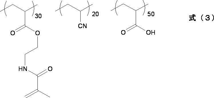
ここで、式(3)中の数値は各ユニットの割合(mol%)を表す。
式(3)で表されるアクリルポリマーの合成方法は以下のとおりである。
2Lの三口フラスコに酢酸エチル1L、2-アミノエタノール159gを入れ、氷浴にて冷却をした。そこへ、2-ブロモイソ酪酸ブロミド150gを内温20℃以下になるように調節して滴下した。その後、内温を室温(25℃)まで上昇させて2時間反応させた。反応終了後、蒸留水300mLを追加して反応を停止させた。その後、酢酸エチル層を蒸留水300mLで4回洗浄後、硫酸マグネシウムで乾燥し、さらに酢酸エチルを留去することで原料Aを80g得た。
次に、500mLの三口フラスコに、原料A47.4g、ピリジン22g、酢酸エチル150mLを入れて氷浴にて冷却した。そこへ、アクリル酸クロライド25gを内温20℃以下になるように調節して滴下した。その後、室温に上げて3時間反応させた。反応終了後、蒸留水300mLを追加し、反応を停止させた。その後、酢酸エチル層を蒸留水300mLで4回洗浄後、硫酸マグネシウムで乾燥し、さらに酢酸エチルを留去した。その後、カラムクロマトグラフィーにて、以下のモノマーM1を精製し20g得た。
式(3)で表されるアクリルポリマーの合成方法は以下のとおりである。
2Lの三口フラスコに酢酸エチル1L、2-アミノエタノール159gを入れ、氷浴にて冷却をした。そこへ、2-ブロモイソ酪酸ブロミド150gを内温20℃以下になるように調節して滴下した。その後、内温を室温(25℃)まで上昇させて2時間反応させた。反応終了後、蒸留水300mLを追加して反応を停止させた。その後、酢酸エチル層を蒸留水300mLで4回洗浄後、硫酸マグネシウムで乾燥し、さらに酢酸エチルを留去することで原料Aを80g得た。
次に、500mLの三口フラスコに、原料A47.4g、ピリジン22g、酢酸エチル150mLを入れて氷浴にて冷却した。そこへ、アクリル酸クロライド25gを内温20℃以下になるように調節して滴下した。その後、室温に上げて3時間反応させた。反応終了後、蒸留水300mLを追加し、反応を停止させた。その後、酢酸エチル層を蒸留水300mLで4回洗浄後、硫酸マグネシウムで乾燥し、さらに酢酸エチルを留去した。その後、カラムクロマトグラフィーにて、以下のモノマーM1を精製し20g得た。

500mLの三口フラスコに、N,N-ジメチルアセトアミド8gを入れ、窒素気流下65℃まで加熱した。そこへ、上記で得たモノマーM1:14.3g、アクリロニトリル(東京化成工業(株)製)3.0g、アクリル酸(東京化成製)6.5g、V-65(和光純薬製)0.4gのN,N-ジメチルアセトアミド8g溶液を、4時間かけて滴下した。滴下終了後、更に3時間撹拌した。その後、N,N-ジメチルアセトアミド41gを足し、室温まで反応溶液を冷却した。上記の反応溶液に、4-ヒドロキシTEMPO(東京化成製)0.09g、DBU54.8gを加え、室温で12時間反応を行った。その後、反応溶液に70質量%メタンスルホン酸水溶液54gを加えた。反応終了後、水で再沈を行い、固形物を取り出し、式(3)で表されるアクリルポリマー(重量平均分子量5.3万)を12g得た。
また、式(3)で表されるアクリルポリマーを含む溶液の調製法は以下のとおりである。
式(3)で表されるアクリルポリマー(7質量部)、1-メトキシ-2-プロパノール(74質量部)、水(19質量部)の割合で混合し、さらにこの混合溶液に対して、光重合開始剤(エサキュアKTO-46、ランベルディー社製)(0.35質量部)を添加して、攪拌混合し、式(3)で表されるアクリルポリマーを含む溶液を得た。
式(3)で表されるアクリルポリマー(7質量部)、1-メトキシ-2-プロパノール(74質量部)、水(19質量部)の割合で混合し、さらにこの混合溶液に対して、光重合開始剤(エサキュアKTO-46、ランベルディー社製)(0.35質量部)を添加して、攪拌混合し、式(3)で表されるアクリルポリマーを含む溶液を得た。
上記塗膜に対して、三永電機製のUV露光機(型番:UVF-502S、ランプ:UXM-501MD)を用いて、254nmの波長で1000mJ/cm2の積算露光量にて照射を行い、プライマー層(厚み:500nm)を形成した。
なお、プライマー層から未反応のポリマーを除去するために現像を行った。具体的には、上記プライマー層付きPET支持体を1wt%炭酸水素ナトリウム水溶液中に5分間浸漬した。その後純水で洗浄した。
なお、プライマー層から未反応のポリマーを除去するために現像を行った。具体的には、上記プライマー層付きPET支持体を1wt%炭酸水素ナトリウム水溶液中に5分間浸漬した。その後純水で洗浄した。
(金属反射層の形成)
次に、プライマー層付きPET支持体を1wt%硝酸銀水溶液中に5分間浸漬し、その後純水で洗浄して、無電解めっき触媒前駆体(銀イオン)が付与されたプライマー層付きPET支持体を得た。
さらに、得られたプライマー層付き樹脂基材を、0.14wt%のNaOHと0.25wt%のホルマリンとを含むアルカリ水溶液(pH12.5)(還元剤に該当)に1分間浸漬し、その後純水で洗浄して、還元金属(銀)が付与されたプライマー層付きPET支持体を得た。
次に、プライマー層付きPET支持体を1wt%硝酸銀水溶液中に5分間浸漬し、その後純水で洗浄して、無電解めっき触媒前駆体(銀イオン)が付与されたプライマー層付きPET支持体を得た。
さらに、得られたプライマー層付き樹脂基材を、0.14wt%のNaOHと0.25wt%のホルマリンとを含むアルカリ水溶液(pH12.5)(還元剤に該当)に1分間浸漬し、その後純水で洗浄して、還元金属(銀)が付与されたプライマー層付きPET支持体を得た。
次に、還元金属(銀)が付与されたプライマー層に対して、以下の電気めっき処理を行い、プライマー層上に厚み200nmの金属(銀)反射層を形成した。
電気めっき液として、ダインシルバーブライトPL50(大和化成社製)を用い、8M水酸化カリウムによりpH9.0に調整した。還元金属を表面にもつプライマー層付きPET支持体を、電気めっき液に浸漬し、0.5A/dm2にて15秒間めっきし、その後、純水で1分間掛け流しにより洗浄した。
電気めっき液として、ダインシルバーブライトPL50(大和化成社製)を用い、8M水酸化カリウムによりpH9.0に調整した。還元金属を表面にもつプライマー層付きPET支持体を、電気めっき液に浸漬し、0.5A/dm2にて15秒間めっきし、その後、純水で1分間掛け流しにより洗浄した。
(表面被覆層の形成)
次に、金属反射層上にウレタン接着剤(東洋インキ製造社製、商品名:LIS825、LCR901)を塗布して、5分間乾燥処理を行い、接着層(厚み:8μm)を製造した。
その後、表面被覆層として、PMMA基板(三菱レイヨン社製、HBS006、厚み:50μm)を接着層上に貼り合わせて、フィルムミラーを作製した。
下記第1表中に、作製したフィルムミラーのサイズ、膜厚、樹脂基材の種類、反射層の種類および表面被覆層の種類を示す。なお、下記第1表中、サイズにおける「□700mm」とは、700mm×700mm四方のことを表す。
次に、金属反射層上にウレタン接着剤(東洋インキ製造社製、商品名:LIS825、LCR901)を塗布して、5分間乾燥処理を行い、接着層(厚み:8μm)を製造した。
その後、表面被覆層として、PMMA基板(三菱レイヨン社製、HBS006、厚み:50μm)を接着層上に貼り合わせて、フィルムミラーを作製した。
下記第1表中に、作製したフィルムミラーのサイズ、膜厚、樹脂基材の種類、反射層の種類および表面被覆層の種類を示す。なお、下記第1表中、サイズにおける「□700mm」とは、700mm×700mm四方のことを表す。
(反射鏡の製造)
まず、作製したフィルムミラーを仮固定用の枠材(サイズ:700mm×700mm四方、幅:25mm、厚み:5mm)に粘着テープを用いてある程度のテンションを掛けた状態で仮固定する。
次いで、アルミニウム(A5052)製の枠状の支持部材(サイズ:500mm×500mm四方、幅:25mm、厚み:10mm、垂直断面形状:図7(A)、出射角度:0°、曲率半径:9mm)の枠表面に粘着剤(ファインタック、DIC社製)を塗布した。
その後、支持部材の粘着剤の塗布面を、仮固定用の枠材(仮枠材)に仮固定したフィルムミラーに対して垂直に貼り合わせ、更に仮枠材の枠内に支持部材を押し込むことにより、反射鏡を作製した。
下記第1表中に、使用した支持部材のサイズ、垂直断面形状、出射角度および曲率半径を示し、また、フィルムミラーの膜厚と支持部材の曲率半径との比率(曲率半径/膜厚)、および、フィルムミラーと支持部材との接合方法を示す。なお、下記第1表中、サイズにおける「□500mm」とは、500mm×500mm四方のことを表す。
まず、作製したフィルムミラーを仮固定用の枠材(サイズ:700mm×700mm四方、幅:25mm、厚み:5mm)に粘着テープを用いてある程度のテンションを掛けた状態で仮固定する。
次いで、アルミニウム(A5052)製の枠状の支持部材(サイズ:500mm×500mm四方、幅:25mm、厚み:10mm、垂直断面形状:図7(A)、出射角度:0°、曲率半径:9mm)の枠表面に粘着剤(ファインタック、DIC社製)を塗布した。
その後、支持部材の粘着剤の塗布面を、仮固定用の枠材(仮枠材)に仮固定したフィルムミラーに対して垂直に貼り合わせ、更に仮枠材の枠内に支持部材を押し込むことにより、反射鏡を作製した。
下記第1表中に、使用した支持部材のサイズ、垂直断面形状、出射角度および曲率半径を示し、また、フィルムミラーの膜厚と支持部材の曲率半径との比率(曲率半径/膜厚)、および、フィルムミラーと支持部材との接合方法を示す。なお、下記第1表中、サイズにおける「□500mm」とは、500mm×500mm四方のことを表す。
<実施例2>
PET基材の厚みを150μmに変更してフィルムミラーの膜厚を0.21mmとした以外は、実施例1と同様の方法により、反射鏡を製造した。
PET基材の厚みを150μmに変更してフィルムミラーの膜厚を0.21mmとした以外は、実施例1と同様の方法により、反射鏡を製造した。
<実施例3>
PET基材の厚みを220μmに変更してフィルムミラーの膜厚を0.28mmとした以外は、実施例1と同様の方法により、反射鏡を製造した。
PET基材の厚みを220μmに変更してフィルムミラーの膜厚を0.28mmとした以外は、実施例1と同様の方法により、反射鏡を製造した。
<実施例4>
プライマー層を形成せず、以下に示す方法で形成した金属反射層を用いた以外は、実施例2と同様の方法により、反射鏡を製造した。
(金属反射層の形成)
PET基材(厚み:150μm、富士フイルム社製)上に、スパッタリング法(PVD)を用いて、TiO2を65nm、SiO2を110nm、交互に形成し、TiO2が8層、SiO2が7層の金属反射層を形成した。
プライマー層を形成せず、以下に示す方法で形成した金属反射層を用いた以外は、実施例2と同様の方法により、反射鏡を製造した。
(金属反射層の形成)
PET基材(厚み:150μm、富士フイルム社製)上に、スパッタリング法(PVD)を用いて、TiO2を65nm、SiO2を110nm、交互に形成し、TiO2が8層、SiO2が7層の金属反射層を形成した。
<実施例5>
アルミニウム(A5052)製の枠状の支持部材(サイズ:500mm×500mm四方、幅:25mm、厚み:10mm、垂直断面形状:図7(A)、出射角度:0°、曲率半径:9mm)に代えて、ステンレス(SUS304)製の枠状の支持部材(サイズ:500mm×500mm、幅:25mm、厚み:10mm、垂直断面形状:図7(A)、出射角度:0°、曲率半径:9mm)を用いた以外は、実施例2と同様の方法により、反射鏡を製造した。
アルミニウム(A5052)製の枠状の支持部材(サイズ:500mm×500mm四方、幅:25mm、厚み:10mm、垂直断面形状:図7(A)、出射角度:0°、曲率半径:9mm)に代えて、ステンレス(SUS304)製の枠状の支持部材(サイズ:500mm×500mm、幅:25mm、厚み:10mm、垂直断面形状:図7(A)、出射角度:0°、曲率半径:9mm)を用いた以外は、実施例2と同様の方法により、反射鏡を製造した。
<実施例6>
アルミニウム(A5052)製の枠状の支持部材(サイズ:500mm×500mm四方、幅:25mm、厚み:10mm、垂直断面形状:図7(A)、出射角度:0°、曲率半径:9mm)に代えて、アルミニウム(A5052)製の枠状の支持部材(サイズ:500mm×500mm四方、幅:25mm、厚み:10mm、垂直断面形状:図7(B)、出射角度:0°、曲率半径:18mm)を用いた以外は、実施例1と同様の方法により、反射鏡を製造した。
アルミニウム(A5052)製の枠状の支持部材(サイズ:500mm×500mm四方、幅:25mm、厚み:10mm、垂直断面形状:図7(A)、出射角度:0°、曲率半径:9mm)に代えて、アルミニウム(A5052)製の枠状の支持部材(サイズ:500mm×500mm四方、幅:25mm、厚み:10mm、垂直断面形状:図7(B)、出射角度:0°、曲率半径:18mm)を用いた以外は、実施例1と同様の方法により、反射鏡を製造した。
<実施例7>
PET基材の厚みを150μmに変更してフィルムミラーの膜厚を0.21mmとした以外は、実施例6と同様の方法により、反射鏡を製造した。
PET基材の厚みを150μmに変更してフィルムミラーの膜厚を0.21mmとした以外は、実施例6と同様の方法により、反射鏡を製造した。
<実施例8>
PET基材の厚みを220μmに変更してフィルムミラーの膜厚を0.28mmとした以外は、実施例6と同様の方法により、反射鏡を製造した。
PET基材の厚みを220μmに変更してフィルムミラーの膜厚を0.28mmとした以外は、実施例6と同様の方法により、反射鏡を製造した。
<実施例9>
アルミニウム(A5052)製の枠状の支持部材(サイズ:500mm×500mm四方、幅:25mm、厚み:10mm、垂直断面形状:図7(A)、出射角度:0°、曲率半径:9mm)に代えて、アルミニウム(A5052)製の枠状の支持部材(サイズ:500mm×500mm四方、幅:25mm、厚み:10mm、垂直断面形状:図7(C)、出射角度:0°、曲率半径:28mm)を用いた以外は、実施例1と同様の方法により、反射鏡を製造した。
アルミニウム(A5052)製の枠状の支持部材(サイズ:500mm×500mm四方、幅:25mm、厚み:10mm、垂直断面形状:図7(A)、出射角度:0°、曲率半径:9mm)に代えて、アルミニウム(A5052)製の枠状の支持部材(サイズ:500mm×500mm四方、幅:25mm、厚み:10mm、垂直断面形状:図7(C)、出射角度:0°、曲率半径:28mm)を用いた以外は、実施例1と同様の方法により、反射鏡を製造した。
<実施例10>
PET基材の厚みを150μmに変更してフィルムミラーの膜厚を0.21mmとした以外は、実施例9と同様の方法により、反射鏡を製造した。
PET基材の厚みを150μmに変更してフィルムミラーの膜厚を0.21mmとした以外は、実施例9と同様の方法により、反射鏡を製造した。
<実施例11>
PET基材の厚みを220μmに変更してフィルムミラーの膜厚を0.28mmとした以外は、実施例9と同様の方法により、反射鏡を製造した。
、反射鏡を製造した。
PET基材の厚みを220μmに変更してフィルムミラーの膜厚を0.28mmとした以外は、実施例9と同様の方法により、反射鏡を製造した。
、反射鏡を製造した。
<実施例12>
アルミニウム(A5052)製の枠状の支持部材(サイズ:500mm×500mm四方、幅:25mm、厚み:10mm、垂直断面形状:図7(A)、出射角度:0°、曲率半径:9mm)に代えて、アルミニウム(A5052)製の枠状の支持部材(サイズ:500mm×500mm四方、幅:25mm、厚み:10mm、垂直断面形状:図7(D)、出射角度:10°、曲率半径:18mm)を用いた以外は、実施例2と同様の方法により、反射鏡を製造した。
アルミニウム(A5052)製の枠状の支持部材(サイズ:500mm×500mm四方、幅:25mm、厚み:10mm、垂直断面形状:図7(A)、出射角度:0°、曲率半径:9mm)に代えて、アルミニウム(A5052)製の枠状の支持部材(サイズ:500mm×500mm四方、幅:25mm、厚み:10mm、垂直断面形状:図7(D)、出射角度:10°、曲率半径:18mm)を用いた以外は、実施例2と同様の方法により、反射鏡を製造した。
<実施例13>
アルミニウム(A5052)製の枠状の支持部材(サイズ:500mm×500mm四方、幅:25mm、厚み:10mm、垂直断面形状:図7(A)、出射角度:0°、曲率半径:9mm)に代えて、アルミニウム(A5052)製の枠状の支持部材(サイズ:500mm×500mm四方、幅:25mm、厚み:10mm、垂直断面形状:図7(E)、出射角度:17°、曲率半径:18mm)を用いた以外は、実施例2と同様の方法により、反射鏡を製造した。
アルミニウム(A5052)製の枠状の支持部材(サイズ:500mm×500mm四方、幅:25mm、厚み:10mm、垂直断面形状:図7(A)、出射角度:0°、曲率半径:9mm)に代えて、アルミニウム(A5052)製の枠状の支持部材(サイズ:500mm×500mm四方、幅:25mm、厚み:10mm、垂直断面形状:図7(E)、出射角度:17°、曲率半径:18mm)を用いた以外は、実施例2と同様の方法により、反射鏡を製造した。
<実施例14>
アルミニウム(A5052)製の枠状の支持部材(サイズ:500mm×500mm四方、幅:25mm、厚み:10mm、垂直断面形状:図7(A)、出射角度:0°、曲率半径:9mm)に代えて、アルミニウム(A5052)製の枠状の支持部材(サイズ:500mm×500mm四方、幅:25mm、厚み:10mm、垂直断面形状:図7(F)、出射角度:30°、曲率半径:18mm)を用いた以外は、実施例2と同様の方法により、反射鏡を製造した。
アルミニウム(A5052)製の枠状の支持部材(サイズ:500mm×500mm四方、幅:25mm、厚み:10mm、垂直断面形状:図7(A)、出射角度:0°、曲率半径:9mm)に代えて、アルミニウム(A5052)製の枠状の支持部材(サイズ:500mm×500mm四方、幅:25mm、厚み:10mm、垂直断面形状:図7(F)、出射角度:30°、曲率半径:18mm)を用いた以外は、実施例2と同様の方法により、反射鏡を製造した。
<比較例1>
PET基材の厚みを350μmに変更してフィルムミラーの膜厚を0.41mmとした以外は、実施例1と同様の方法により、反射鏡を製造した。
PET基材の厚みを350μmに変更してフィルムミラーの膜厚を0.41mmとした以外は、実施例1と同様の方法により、反射鏡を製造した。
<比較例2>
アルミニウム(A5052)製の枠状の支持部材(サイズ:500mm×500mm四方、幅:25mm、厚み:10mm、垂直断面形状:図7(A)、出射角度:0°、曲率半径:9mm)に代えて、アルミニウム(A5052)製の枠状の支持部材(サイズ:500mm×500mm四方、幅:25mm、厚み:10mm、垂直断面形状:図7(A)、出射角度:0°、曲率半径:6mm)を用いた以外は、実施例2と同様の方法により、反射鏡を製造した。
アルミニウム(A5052)製の枠状の支持部材(サイズ:500mm×500mm四方、幅:25mm、厚み:10mm、垂直断面形状:図7(A)、出射角度:0°、曲率半径:9mm)に代えて、アルミニウム(A5052)製の枠状の支持部材(サイズ:500mm×500mm四方、幅:25mm、厚み:10mm、垂直断面形状:図7(A)、出射角度:0°、曲率半径:6mm)を用いた以外は、実施例2と同様の方法により、反射鏡を製造した。
<比較例3>
支持部材を用いず、実施例2で作製したフィルムミラーの樹脂基材側に粘着剤(ファインタック、DIC社製)を塗布し、被着体(SUS304)と接合させた。
支持部材を用いず、実施例2で作製したフィルムミラーの樹脂基材側に粘着剤(ファインタック、DIC社製)を塗布し、被着体(SUS304)と接合させた。
作製した各反射鏡(比較例3においてはフィルムミラーをいう。以下、同様。)について、反り量、正反射性、集光特性および耐熱性を以下に示す方法に評価し、それらの結果を下記第1表に示す。なお、比較例3については、支持部材がないため、反り量については測定せず、下記第1表においては「-」と表記している。
<反り量>
作製した各反射鏡の反り量(図2においては符号C)を測定した。なお、測定は、反射鏡の側面をCCDカメラで撮影(ピクセルサイズ:2.5μm×2.5μm)し、その撮影画像から反り量を算出した。
また、以下の基準にしたがって評価した。
AA:反り量が20μm未満
A:反り量が20μm以上75μm未満
B:反り量が75μm以上100μm未満
C:反り量が100μm以上
作製した各反射鏡の反り量(図2においては符号C)を測定した。なお、測定は、反射鏡の側面をCCDカメラで撮影(ピクセルサイズ:2.5μm×2.5μm)し、その撮影画像から反り量を算出した。
また、以下の基準にしたがって評価した。
AA:反り量が20μm未満
A:反り量が20μm以上75μm未満
B:反り量が75μm以上100μm未満
C:反り量が100μm以上
<正反射性(拡散成分比率)>
作製した各反射鏡の正反射性の評価は、全反射光に対する拡散成分のエネルギー比率を算出して行った。
具体的には、光源用LEDから反射鏡上に光を照射させ、その反射光をレンズを通して、CCDイメージセンサに画像として受光させ、得られた画像における正反射成分と拡散成分との合計面積中の拡散成分の占める割合から算出した。
また、以下の基準にしたがって評価した。
AA:拡散成分比率が2.0%未満
A:拡散成分比率が2.0%以上5.0%未満
B:拡散成分比率が5.0%以上10.0%未満
C:拡散成分比率が10.0%以上
作製した各反射鏡の正反射性の評価は、全反射光に対する拡散成分のエネルギー比率を算出して行った。
具体的には、光源用LEDから反射鏡上に光を照射させ、その反射光をレンズを通して、CCDイメージセンサに画像として受光させ、得られた画像における正反射成分と拡散成分との合計面積中の拡散成分の占める割合から算出した。
また、以下の基準にしたがって評価した。
AA:拡散成分比率が2.0%未満
A:拡散成分比率が2.0%以上5.0%未満
B:拡散成分比率が5.0%以上10.0%未満
C:拡散成分比率が10.0%以上
<集光特性>
作製した各反射鏡の集光特性の評価は、反射鏡で反射した太陽光の光量(エネルギー)をフォトダイオードで計測した。
具体的には、図8に示すように、受光板20の表面にフォトダイオード(図示せず)を正方格子状に10cm間隔で計25点(5×5)設置し、光量の平均値を算出した。なお、図8に示すように、受光板20と反射鏡1との距離は30mとし、太陽光(入射光)と反射鏡1との角度、反射鏡1と反射光(受光板20)の角度はそれぞれ10°とした。
また、以下の基準にしたがって評価した。
AA:太陽光エネルギーの95%以上
A:太陽光エネルギーの90%以上95%未満
B:太陽光エネルギーの80%以上90%未満
C:太陽光エネルギーの80%未満
作製した各反射鏡の集光特性の評価は、反射鏡で反射した太陽光の光量(エネルギー)をフォトダイオードで計測した。
具体的には、図8に示すように、受光板20の表面にフォトダイオード(図示せず)を正方格子状に10cm間隔で計25点(5×5)設置し、光量の平均値を算出した。なお、図8に示すように、受光板20と反射鏡1との距離は30mとし、太陽光(入射光)と反射鏡1との角度、反射鏡1と反射光(受光板20)の角度はそれぞれ10°とした。
また、以下の基準にしたがって評価した。
AA:太陽光エネルギーの95%以上
A:太陽光エネルギーの90%以上95%未満
B:太陽光エネルギーの80%以上90%未満
C:太陽光エネルギーの80%未満
<耐熱性(温度サイクル)>
作製した各反射鏡の温度サイクルは、-40℃の条件下での30分放置と65℃条件下での30分放置とを3000回繰り返した後のフィルムミラーの皺、うねり、剥がれ等の面状故障を観察し、以下の基準にしたがって評価した。
AA:サイクル数を2倍の6000回に増やしても面状故障が発生しない。
A:面状故障が発生しない。
B:面状故障が僅かに発生する。
C:フィルムミラーと支持部材との剥がれが一部領域で発生する。
D:面状故障が顕著に発生する。
作製した各反射鏡の温度サイクルは、-40℃の条件下での30分放置と65℃条件下での30分放置とを3000回繰り返した後のフィルムミラーの皺、うねり、剥がれ等の面状故障を観察し、以下の基準にしたがって評価した。
AA:サイクル数を2倍の6000回に増やしても面状故障が発生しない。
A:面状故障が発生しない。
B:面状故障が僅かに発生する。
C:フィルムミラーと支持部材との剥がれが一部領域で発生する。
D:面状故障が顕著に発生する。
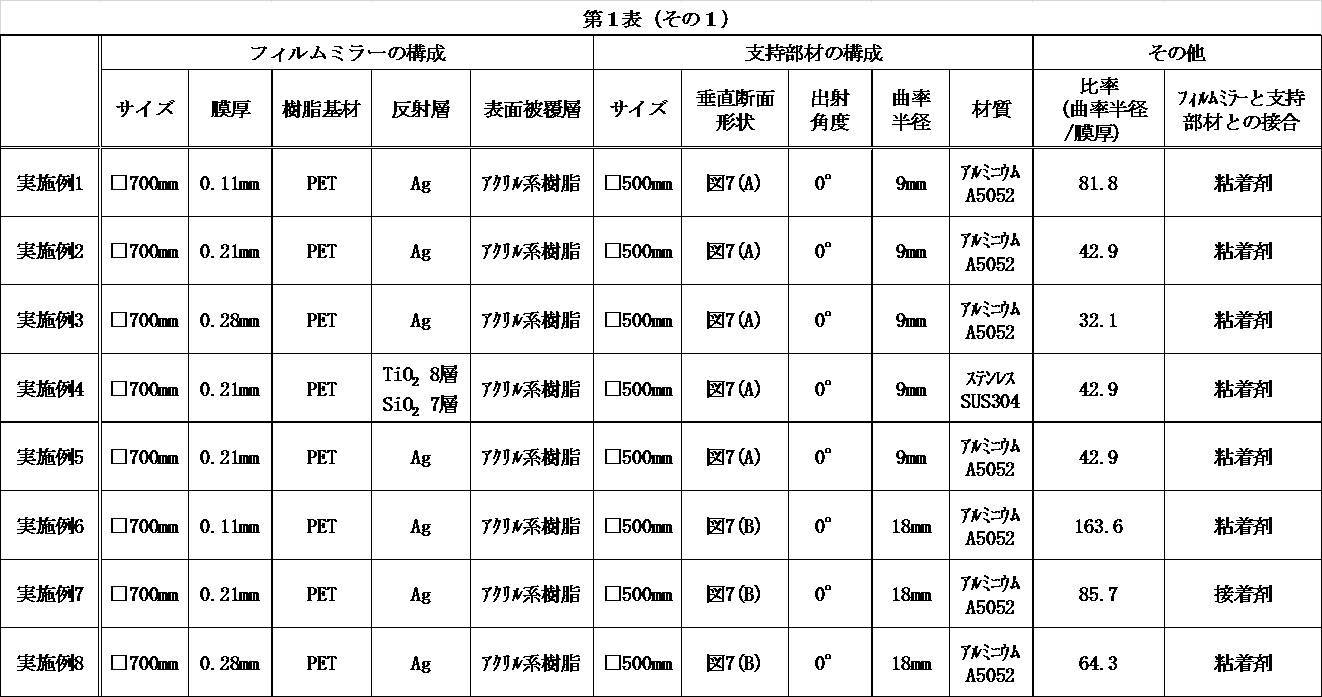

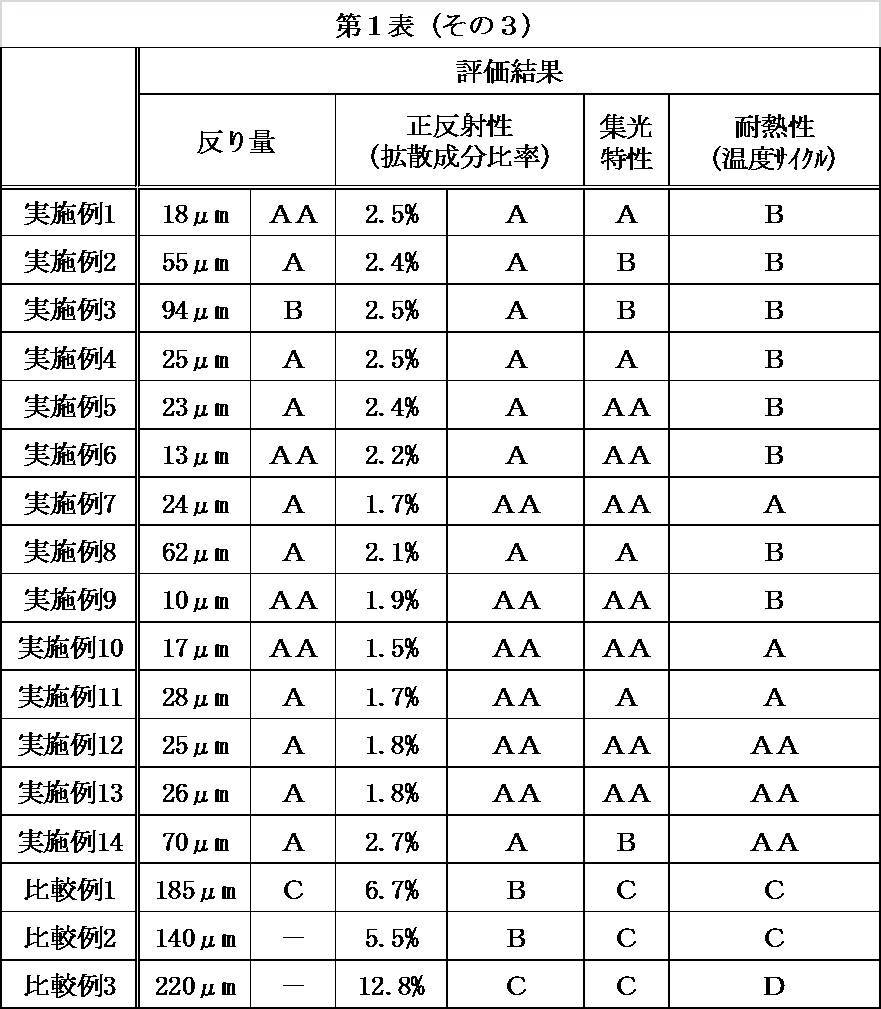
第1表に示す結果から、支持部材を用いずに、フィルムミラーを直接被着体と接合した反射鏡は、耐熱性に劣り、正反射性および集光特性も劣ることが分かった(比較例3)。
また、フィルムミラーの膜厚が0.30mmより厚い反射鏡は、耐熱性に劣り、更に、フィルムミラーの反り量が大きくなり、正反射性および集光特性も劣ることが分かった(比較例1)。
また、所定の膜厚を有するフィルムミラーを用いた場合であっても、曲率半径が小さい支持部材を用いた反射鏡は、耐熱性に劣り、更に、フィルムミラーの反り量が大きくなり、正反射性および集光特性も劣ることが分かった(比較例2)。
これに対し、所定の膜厚を有するフィルムミラーと特定の曲率半径の湾曲面を所定の位置に有する支持部材とを具備する反射鏡は、いずれも耐熱性に優れ、かつ、フィルムミラーの反り量が小さく、正反射性および集光特性に優れることが分かった(実施例1~14)。
特に、フィルムミラーの膜厚と支持部材における湾曲面の曲率半径との比率(曲率半径/膜厚)が80以上となる実施例1、6、7および9~14は、フィルムミラーの反り量がより小さくなり、反射鏡の集光特性がより良好となることが分かった。
同様に、支持部材における湾曲面の曲率半径が15mm以上となる実施例6~14は、フィルムミラーの反り量がより小さくなり、反射鏡の集光特性がより良好となることが分かった。
また、フィルムミラーの膜厚が0.30mmより厚い反射鏡は、耐熱性に劣り、更に、フィルムミラーの反り量が大きくなり、正反射性および集光特性も劣ることが分かった(比較例1)。
また、所定の膜厚を有するフィルムミラーを用いた場合であっても、曲率半径が小さい支持部材を用いた反射鏡は、耐熱性に劣り、更に、フィルムミラーの反り量が大きくなり、正反射性および集光特性も劣ることが分かった(比較例2)。
これに対し、所定の膜厚を有するフィルムミラーと特定の曲率半径の湾曲面を所定の位置に有する支持部材とを具備する反射鏡は、いずれも耐熱性に優れ、かつ、フィルムミラーの反り量が小さく、正反射性および集光特性に優れることが分かった(実施例1~14)。
特に、フィルムミラーの膜厚と支持部材における湾曲面の曲率半径との比率(曲率半径/膜厚)が80以上となる実施例1、6、7および9~14は、フィルムミラーの反り量がより小さくなり、反射鏡の集光特性がより良好となることが分かった。
同様に、支持部材における湾曲面の曲率半径が15mm以上となる実施例6~14は、フィルムミラーの反り量がより小さくなり、反射鏡の集光特性がより良好となることが分かった。
1 反射鏡
2 フィルムミラー
3 支持部材
3a 開口面
3b 湾曲面
5 射出点
10 フィルムミラー
20 受光板
11 樹脂基材
12 金属反射層
13 表面被覆層
100 フィルムミラー
101 第1の表面被覆層
102 第1の金属反射層
103 樹脂基材
104 第2の金属反射層
105 第2の表面被覆層
106 第1の樹脂基材
107 金属反射層
108 第2の樹脂基材
2 フィルムミラー
3 支持部材
3a 開口面
3b 湾曲面
5 射出点
10 フィルムミラー
20 受光板
11 樹脂基材
12 金属反射層
13 表面被覆層
100 フィルムミラー
101 第1の表面被覆層
102 第1の金属反射層
103 樹脂基材
104 第2の金属反射層
105 第2の表面被覆層
106 第1の樹脂基材
107 金属反射層
108 第2の樹脂基材
Claims (8)
- フィルムミラーと、前記フィルムミラーの周縁部を支持する枠形状の支持部材とを有する、太陽光集光用反射鏡であって、
前記フィルムミラーの膜厚が、0.10~0.30mmであり、
前記支持部材が、前記フィルムミラーと接し、かつ、前記支持部材の開口面に対して水平方向外向きに凸状に湾曲した湾曲面を有し、
前記湾曲面の曲率半径が8mm以上である太陽光集光用反射鏡。 - 前記フィルムミラーの膜厚と前記支持部材における前記湾曲面の曲率半径との比率(曲率半径/膜厚)が、80以上である請求項1に記載の太陽光集光用反射鏡。
- 前記支持部材における前記湾曲面の曲率半径が、15mm以上である請求項1または2に記載の太陽光集光用反射鏡。
- 前記支持部材の開口面と垂直な断面において前記フィルムミラーと前記支持部材とが離れる点における前記支持部材の接線と、前記支持部材の開口面とのなす角が、0°以上20°以下である請求項1~3のいずれか1項に記載の太陽光集光用反射鏡。
- 前記フィルムミラーが、樹脂基材、金属反射層および表面被覆層を有する多角形状のフィルムミラーである請求項1~4のいずれか1項に記載の太陽光集光用反射鏡。
- 前記フィルムミラーの形状が、矩形状である請求項1~5のいずれか1項に記載の太陽光集光用反射鏡。
- 前記フィルムミラーが、第1の表面被覆層、第1の金属反射層、樹脂基材、第2の金属反射層および第2の表面被覆層をこの順に有するフィルムミラーである請求項1~6のいずれか1項に記載の太陽光集光用反射鏡。
- 前記フィルムミラーが、第1の表面被覆層、第1の樹脂基材、金属反射層、第2の樹脂基材および第2の表面被覆層をこの順に有するフィルムミラーである請求項1~6のいずれか1項に記載の太陽光集光用反射鏡。
Priority Applications (2)
| Application Number | Priority Date | Filing Date | Title |
|---|---|---|---|
| EP14754171.8A EP2960689B1 (en) | 2013-02-21 | 2014-01-31 | Sunlight-collecting reflective mirror |
| US14/825,255 US20150370036A1 (en) | 2013-02-21 | 2015-08-13 | Sunlight-collecting reflective mirror |
Applications Claiming Priority (2)
| Application Number | Priority Date | Filing Date | Title |
|---|---|---|---|
| JP2013032325A JP6029486B2 (ja) | 2013-02-21 | 2013-02-21 | 太陽光集光用反射鏡 |
| JP2013-032325 | 2013-02-21 |
Related Child Applications (1)
| Application Number | Title | Priority Date | Filing Date |
|---|---|---|---|
| US14/825,255 Continuation US20150370036A1 (en) | 2013-02-21 | 2015-08-13 | Sunlight-collecting reflective mirror |
Publications (1)
| Publication Number | Publication Date |
|---|---|
| WO2014129290A1 true WO2014129290A1 (ja) | 2014-08-28 |
Family
ID=51391087
Family Applications (1)
| Application Number | Title | Priority Date | Filing Date |
|---|---|---|---|
| PCT/JP2014/052244 Ceased WO2014129290A1 (ja) | 2013-02-21 | 2014-01-31 | 太陽光集光用反射鏡 |
Country Status (4)
| Country | Link |
|---|---|
| US (1) | US20150370036A1 (ja) |
| EP (1) | EP2960689B1 (ja) |
| JP (1) | JP6029486B2 (ja) |
| WO (1) | WO2014129290A1 (ja) |
Families Citing this family (2)
| Publication number | Priority date | Publication date | Assignee | Title |
|---|---|---|---|---|
| JP2018136373A (ja) * | 2017-02-20 | 2018-08-30 | 徹 奥田 | 反射板およびそれに用いる挟持具 |
| JP7519150B1 (ja) | 2024-04-11 | 2024-07-19 | 合同会社北海道環境・エネルギー研究所 | 柱面体作製方法及びその作製方法を用いて作製された柱面体 |
Citations (8)
| Publication number | Priority date | Publication date | Assignee | Title |
|---|---|---|---|---|
| JPH03293301A (ja) | 1990-04-11 | 1991-12-25 | Mitsubishi Heavy Ind Ltd | 反射鏡 |
| JPH09311207A (ja) * | 1996-05-17 | 1997-12-02 | Matsushita Electric Ind Co Ltd | ミラーとフィルムとテレビジョン受像機 |
| JP2004077643A (ja) * | 2002-08-13 | 2004-03-11 | Ado Union Kenkyusho:Kk | 背面投射型テレビジョン受像機の反射鏡 |
| US20040119895A1 (en) * | 2002-09-19 | 2004-06-24 | Kang Taeg Ho | Reflection mirror of projection television and fabrication method thereof |
| JP2004270552A (ja) * | 2003-03-07 | 2004-09-30 | National Aerospace Laboratory Of Japan | 太陽熱推進システム、及びそれを用いた使用済み人工衛星の自主廃棄方法 |
| WO2011122241A1 (ja) * | 2010-03-27 | 2011-10-06 | コニカミノルタオプト株式会社 | 太陽熱発電用フィルムミラー、太陽熱発電用フィルムミラーの製造方法及び太陽熱発電用反射装置 |
| WO2012133517A1 (ja) * | 2011-03-31 | 2012-10-04 | コニカミノルタアドバンストレイヤー株式会社 | ミラー及び太陽熱発電用反射装置 |
| WO2013015190A1 (ja) * | 2011-07-26 | 2013-01-31 | コニカミノルタアドバンストレイヤー株式会社 | 太陽光集光用ミラー及び当該太陽光集光用ミラーを有する太陽熱発電システム |
Family Cites Families (15)
| Publication number | Priority date | Publication date | Assignee | Title |
|---|---|---|---|---|
| US3054328A (en) * | 1958-12-23 | 1962-09-18 | George Gordon | Inflatable curved mirror |
| DE1199017B (de) * | 1962-06-22 | 1965-08-19 | Boelkow Gmbh | Spiegel fuer den Gebrauch im Weltraum |
| DE2405134C2 (de) * | 1974-01-30 | 1985-08-08 | Reinhart Dipl.-Phys. Dr.-Ing. 1000 Berlin Radebold | Verfahren zur Speicherung von Exergie in Form freier Enthalpie chemischer Verbindungen und Anordnung zur Durchführung des Verfahrens |
| US4511215A (en) * | 1983-04-29 | 1985-04-16 | The United States Of America As Represented By The United States Department Of Energy | Lightweight diaphragm mirror module system for solar collectors |
| JPH02169243A (ja) * | 1988-12-23 | 1990-06-29 | Mitsui Toatsu Chem Inc | 反射体 |
| US5680262A (en) * | 1993-02-12 | 1997-10-21 | Cummins Power Generation, Inc. | Stretched membrane mirror and method of making same |
| JPH07209508A (ja) * | 1994-01-18 | 1995-08-11 | Mitsubishi Heavy Ind Ltd | 宇宙集光器用反射鏡及びその製造方法 |
| GB0016777D0 (en) * | 2000-07-07 | 2000-08-30 | Seos Displays Ltd | Improved film mirror |
| US7160326B2 (en) * | 2002-06-27 | 2007-01-09 | Depuy Products, Inc. | Method and apparatus for implantation of soft tissue implant |
| EP2386047B1 (en) * | 2008-08-12 | 2017-07-12 | Sattler AG | Lightweight low-cost solar concentrator |
| JP5424091B2 (ja) * | 2009-03-31 | 2014-02-26 | コニカミノルタ株式会社 | 紫外反射膜を有するフィルムミラー |
| US20120268811A1 (en) * | 2009-12-21 | 2012-10-25 | Konica Minolta Advanced Layers, Inc. | Film mirror, method for producing same, and reflecting device for solar thermal power generation using said film mirror |
| DE202010006792U1 (de) * | 2010-05-14 | 2010-08-05 | Dressel, Philipp | Überdruckgesteuerter Hohlspiegel |
| JP2012255981A (ja) * | 2011-06-10 | 2012-12-27 | Konica Minolta Advanced Layers Inc | 太陽光集光用ミラー及び太陽熱発電システム |
| ES2653766T3 (es) * | 2012-08-01 | 2018-02-08 | Sattler Ag | Espejo de concentración de luz inflable |
-
2013
- 2013-02-21 JP JP2013032325A patent/JP6029486B2/ja not_active Expired - Fee Related
-
2014
- 2014-01-31 WO PCT/JP2014/052244 patent/WO2014129290A1/ja not_active Ceased
- 2014-01-31 EP EP14754171.8A patent/EP2960689B1/en not_active Not-in-force
-
2015
- 2015-08-13 US US14/825,255 patent/US20150370036A1/en not_active Abandoned
Patent Citations (8)
| Publication number | Priority date | Publication date | Assignee | Title |
|---|---|---|---|---|
| JPH03293301A (ja) | 1990-04-11 | 1991-12-25 | Mitsubishi Heavy Ind Ltd | 反射鏡 |
| JPH09311207A (ja) * | 1996-05-17 | 1997-12-02 | Matsushita Electric Ind Co Ltd | ミラーとフィルムとテレビジョン受像機 |
| JP2004077643A (ja) * | 2002-08-13 | 2004-03-11 | Ado Union Kenkyusho:Kk | 背面投射型テレビジョン受像機の反射鏡 |
| US20040119895A1 (en) * | 2002-09-19 | 2004-06-24 | Kang Taeg Ho | Reflection mirror of projection television and fabrication method thereof |
| JP2004270552A (ja) * | 2003-03-07 | 2004-09-30 | National Aerospace Laboratory Of Japan | 太陽熱推進システム、及びそれを用いた使用済み人工衛星の自主廃棄方法 |
| WO2011122241A1 (ja) * | 2010-03-27 | 2011-10-06 | コニカミノルタオプト株式会社 | 太陽熱発電用フィルムミラー、太陽熱発電用フィルムミラーの製造方法及び太陽熱発電用反射装置 |
| WO2012133517A1 (ja) * | 2011-03-31 | 2012-10-04 | コニカミノルタアドバンストレイヤー株式会社 | ミラー及び太陽熱発電用反射装置 |
| WO2013015190A1 (ja) * | 2011-07-26 | 2013-01-31 | コニカミノルタアドバンストレイヤー株式会社 | 太陽光集光用ミラー及び当該太陽光集光用ミラーを有する太陽熱発電システム |
Non-Patent Citations (1)
| Title |
|---|
| See also references of EP2960689A4 |
Also Published As
| Publication number | Publication date |
|---|---|
| JP2014163990A (ja) | 2014-09-08 |
| EP2960689A1 (en) | 2015-12-30 |
| JP6029486B2 (ja) | 2016-11-24 |
| EP2960689B1 (en) | 2019-01-16 |
| EP2960689A4 (en) | 2016-01-06 |
| US20150370036A1 (en) | 2015-12-24 |
Similar Documents
| Publication | Publication Date | Title |
|---|---|---|
| US10619248B2 (en) | Conductive laminate for touch panel, touch panel, and transparent conductive laminate | |
| TW201734740A (zh) | 導電性積層體的製造方法以及帶被鍍覆層前驅體層的立體結構物、帶圖案狀被鍍覆層的立體結構物、導電性積層體、觸控感測器、發熱構件及立體結構物 | |
| JP6016695B2 (ja) | フィルムミラー | |
| JP2014193545A (ja) | 凹面鏡及びその加工方法 | |
| JP2015084068A (ja) | 太陽光集光用フィルムミラーおよびその製造方法 | |
| US20150198753A1 (en) | Film mirror | |
| JP6029486B2 (ja) | 太陽光集光用反射鏡 | |
| WO2014122991A1 (ja) | 太陽光集光用反射鏡 | |
| JP2014199363A (ja) | フィルムミラー | |
| JP2014133403A (ja) | ミラーフィルム、その製造方法、及びそれを用いた反射鏡 | |
| WO2014129297A1 (ja) | フィルムミラーの製造方法およびフィルムミラー | |
| JP2016137666A (ja) | 光反射フィルム、ならびにこれを用いた光反射体および光反射装置 | |
| JP2014178670A (ja) | フィルムミラー | |
| JP2014191094A (ja) | 太陽光集光用フィルムミラー | |
| JP2014191264A (ja) | フィルムミラー | |
| JP2014199319A (ja) | 太陽光集光用フィルムミラーの製造方法および太陽光集光用フィルムミラー | |
| JP2014191230A (ja) | 太陽光集光用フィルムミラー | |
| JP6612970B2 (ja) | 積層体、パターン状被めっき層付き基板の製造方法、金属層含有積層体の製造方法、タッチパネルセンサー、及びタッチパネル | |
| WO2014157355A1 (ja) | フィルムミラー | |
| JP2014191171A (ja) | フィルムミラー | |
| JP2014194469A (ja) | 太陽光集光用フィルムミラー及びその製造方法、並びに太陽光反射板 | |
| JP2014199292A (ja) | フィルムミラー及びその製造方法、並びに太陽光反射板 | |
| JP2014191086A (ja) | 太陽光集光用反射ミラー | |
| WO2014156475A1 (ja) | フィルムミラー | |
| JP2014191203A (ja) | フィルムミラー |
Legal Events
| Date | Code | Title | Description |
|---|---|---|---|
| 121 | Ep: the epo has been informed by wipo that ep was designated in this application |
Ref document number: 14754171 Country of ref document: EP Kind code of ref document: A1 |
|
| WWE | Wipo information: entry into national phase |
Ref document number: 2014754171 Country of ref document: EP |
|
| NENP | Non-entry into the national phase |
Ref country code: DE |