WO2014132910A1 - Structure de partie multicouche - Google Patents
Structure de partie multicouche Download PDFInfo
- Publication number
- WO2014132910A1 WO2014132910A1 PCT/JP2014/054285 JP2014054285W WO2014132910A1 WO 2014132910 A1 WO2014132910 A1 WO 2014132910A1 JP 2014054285 W JP2014054285 W JP 2014054285W WO 2014132910 A1 WO2014132910 A1 WO 2014132910A1
- Authority
- WO
- WIPO (PCT)
- Prior art keywords
- core material
- cutting
- skin material
- sewing
- cutting tool
- Prior art date
- Legal status (The legal status is an assumption and is not a legal conclusion. Google has not performed a legal analysis and makes no representation as to the accuracy of the status listed.)
- Ceased
Links
Images






Classifications
-
- B—PERFORMING OPERATIONS; TRANSPORTING
- B32—LAYERED PRODUCTS
- B32B—LAYERED PRODUCTS, i.e. PRODUCTS BUILT-UP OF STRATA OF FLAT OR NON-FLAT, e.g. CELLULAR OR HONEYCOMB, FORM
- B32B5/00—Layered products characterised by the non- homogeneity or physical structure, i.e. comprising a fibrous, filamentary, particulate or foam layer; Layered products characterised by having a layer differing constitutionally or physically in different parts
- B32B5/18—Layered products characterised by the non- homogeneity or physical structure, i.e. comprising a fibrous, filamentary, particulate or foam layer; Layered products characterised by having a layer differing constitutionally or physically in different parts characterised by features of a layer of foamed material
-
- B—PERFORMING OPERATIONS; TRANSPORTING
- B29—WORKING OF PLASTICS; WORKING OF SUBSTANCES IN A PLASTIC STATE IN GENERAL
- B29C—SHAPING OR JOINING OF PLASTICS; SHAPING OF MATERIAL IN A PLASTIC STATE, NOT OTHERWISE PROVIDED FOR; AFTER-TREATMENT OF THE SHAPED PRODUCTS, e.g. REPAIRING
- B29C44/00—Shaping by internal pressure generated in the material, e.g. swelling or foaming ; Producing porous or cellular expanded plastics articles
- B29C44/02—Shaping by internal pressure generated in the material, e.g. swelling or foaming ; Producing porous or cellular expanded plastics articles for articles of definite length, i.e. discrete articles
- B29C44/12—Incorporating or moulding on preformed parts, e.g. inserts or reinforcements
- B29C44/1228—Joining preformed parts by the expanding material
-
- B—PERFORMING OPERATIONS; TRANSPORTING
- B29—WORKING OF PLASTICS; WORKING OF SUBSTANCES IN A PLASTIC STATE IN GENERAL
- B29C—SHAPING OR JOINING OF PLASTICS; SHAPING OF MATERIAL IN A PLASTIC STATE, NOT OTHERWISE PROVIDED FOR; AFTER-TREATMENT OF THE SHAPED PRODUCTS, e.g. REPAIRING
- B29C44/00—Shaping by internal pressure generated in the material, e.g. swelling or foaming ; Producing porous or cellular expanded plastics articles
- B29C44/34—Auxiliary operations
- B29C44/56—After-treatment of articles, e.g. for altering the shape
- B29C44/5627—After-treatment of articles, e.g. for altering the shape by mechanical deformation, e.g. crushing, embossing, stretching
-
- B—PERFORMING OPERATIONS; TRANSPORTING
- B32—LAYERED PRODUCTS
- B32B—LAYERED PRODUCTS, i.e. PRODUCTS BUILT-UP OF STRATA OF FLAT OR NON-FLAT, e.g. CELLULAR OR HONEYCOMB, FORM
- B32B27/00—Layered products comprising a layer of synthetic resin
- B32B27/06—Layered products comprising a layer of synthetic resin as the main or only constituent of a layer, which is next to another layer of the same or of a different material
- B32B27/065—Layered products comprising a layer of synthetic resin as the main or only constituent of a layer, which is next to another layer of the same or of a different material of foam
-
- B—PERFORMING OPERATIONS; TRANSPORTING
- B32—LAYERED PRODUCTS
- B32B—LAYERED PRODUCTS, i.e. PRODUCTS BUILT-UP OF STRATA OF FLAT OR NON-FLAT, e.g. CELLULAR OR HONEYCOMB, FORM
- B32B7/00—Layered products characterised by the relation between layers; Layered products characterised by the relative orientation of features between layers, or by the relative values of a measurable parameter between layers, i.e. products comprising layers having different physical, chemical or physicochemical properties; Layered products characterised by the interconnection of layers
- B32B7/04—Interconnection of layers
- B32B7/08—Interconnection of layers by mechanical means
- B32B7/09—Interconnection of layers by mechanical means by stitching, needling or sewing
-
- B—PERFORMING OPERATIONS; TRANSPORTING
- B60—VEHICLES IN GENERAL
- B60R—VEHICLES, VEHICLE FITTINGS, OR VEHICLE PARTS, NOT OTHERWISE PROVIDED FOR
- B60R13/00—Elements for body-finishing, identifying, or decorating; Arrangements or adaptations for advertising purposes
- B60R13/02—Internal Trim mouldings ; Internal Ledges; Wall liners for passenger compartments; Roof liners
-
- B—PERFORMING OPERATIONS; TRANSPORTING
- B29—WORKING OF PLASTICS; WORKING OF SUBSTANCES IN A PLASTIC STATE IN GENERAL
- B29C—SHAPING OR JOINING OF PLASTICS; SHAPING OF MATERIAL IN A PLASTIC STATE, NOT OTHERWISE PROVIDED FOR; AFTER-TREATMENT OF THE SHAPED PRODUCTS, e.g. REPAIRING
- B29C44/00—Shaping by internal pressure generated in the material, e.g. swelling or foaming ; Producing porous or cellular expanded plastics articles
- B29C44/02—Shaping by internal pressure generated in the material, e.g. swelling or foaming ; Producing porous or cellular expanded plastics articles for articles of definite length, i.e. discrete articles
- B29C44/12—Incorporating or moulding on preformed parts, e.g. inserts or reinforcements
- B29C44/14—Incorporating or moulding on preformed parts, e.g. inserts or reinforcements the preformed part being a lining
-
- B—PERFORMING OPERATIONS; TRANSPORTING
- B29—WORKING OF PLASTICS; WORKING OF SUBSTANCES IN A PLASTIC STATE IN GENERAL
- B29L—INDEXING SCHEME ASSOCIATED WITH SUBCLASS B29C, RELATING TO PARTICULAR ARTICLES
- B29L2031/00—Other particular articles
- B29L2031/30—Vehicles, e.g. ships or aircraft, or body parts thereof
- B29L2031/3005—Body finishings
- B29L2031/3008—Instrument panels
-
- B—PERFORMING OPERATIONS; TRANSPORTING
- B32—LAYERED PRODUCTS
- B32B—LAYERED PRODUCTS, i.e. PRODUCTS BUILT-UP OF STRATA OF FLAT OR NON-FLAT, e.g. CELLULAR OR HONEYCOMB, FORM
- B32B2307/00—Properties of the layers or laminate
- B32B2307/50—Properties of the layers or laminate having particular mechanical properties
- B32B2307/54—Yield strength; Tensile strength
-
- B—PERFORMING OPERATIONS; TRANSPORTING
- B32—LAYERED PRODUCTS
- B32B—LAYERED PRODUCTS, i.e. PRODUCTS BUILT-UP OF STRATA OF FLAT OR NON-FLAT, e.g. CELLULAR OR HONEYCOMB, FORM
- B32B2307/00—Properties of the layers or laminate
- B32B2307/70—Other properties
- B32B2307/744—Non-slip, anti-slip
-
- B—PERFORMING OPERATIONS; TRANSPORTING
- B32—LAYERED PRODUCTS
- B32B—LAYERED PRODUCTS, i.e. PRODUCTS BUILT-UP OF STRATA OF FLAT OR NON-FLAT, e.g. CELLULAR OR HONEYCOMB, FORM
- B32B2605/00—Vehicles
- B32B2605/003—Interior finishings
-
- B—PERFORMING OPERATIONS; TRANSPORTING
- B60—VEHICLES IN GENERAL
- B60R—VEHICLES, VEHICLE FITTINGS, OR VEHICLE PARTS, NOT OTHERWISE PROVIDED FOR
- B60R13/00—Elements for body-finishing, identifying, or decorating; Arrangements or adaptations for advertising purposes
- B60R13/02—Internal Trim mouldings ; Internal Ledges; Wall liners for passenger compartments; Roof liners
- B60R2013/0281—Internal Trim mouldings ; Internal Ledges; Wall liners for passenger compartments; Roof liners made of a plurality of visible parts
-
- B—PERFORMING OPERATIONS; TRANSPORTING
- B60—VEHICLES IN GENERAL
- B60R—VEHICLES, VEHICLE FITTINGS, OR VEHICLE PARTS, NOT OTHERWISE PROVIDED FOR
- B60R13/00—Elements for body-finishing, identifying, or decorating; Arrangements or adaptations for advertising purposes
- B60R13/02—Internal Trim mouldings ; Internal Ledges; Wall liners for passenger compartments; Roof liners
- B60R2013/0287—Internal Trim mouldings ; Internal Ledges; Wall liners for passenger compartments; Roof liners integrating other functions or accessories
Definitions
- This invention relates to a multi-layer part structure in which a skin material or the like is appropriately cut.
- Vehicle interior parts such as an instrument panel are installed in the front part of a vehicle interior such as an automobile.
- attachment parts for example, a ventilator grill, a decoration panel, etc. which were comprised as another member are attached to such an instrument panel.
- These accessory parts are attached later to an opening or a recess formed in advance in a predetermined position of the instrument panel.
- the vehicle interior parts described above are composed of multilayer parts having a multilayer structure formed by integrating a foam layer having a cushioning property between a hard core material and a soft skin material. Is present.
- a multi-layered interior part for example, injects a foaming liquid as a raw material of the foam layer between the core material and the skin material set in the foaming mold, and the foaming liquid is injected into the foaming mold. It is manufactured by so-called foam molding in which a foam layer is formed by foaming.
- a foam layer is provided at the locations where the openings and recesses are formed during foam molding.
- Do not open / concave part formation part for example, form a two-layer laminated part of core material / skin material, or other parts with the thickness of the foam layer where the opening part or concave part is formed during foam molding
- a thinner opening / recess formation planned portion for example, a three-layer laminated portion of a core material, a foam layer, and a skin material is formed.
- the core material exposed portion is formed by appropriately processing the inner portion of the opening / recessed portion formation scheduled portion using a cutting tool such as a hot blade. And the above-mentioned accessory parts are attached using this core material exposure part.
- the two-layer laminated part of the core material / skin material or the three-layer laminated part of the core material / foamed layer / skin material inside the opening / recessed portion forming portion is cut with a hot blade or the like.
- a hot blade or the like By punching with a tool, an opening, that is, a core material opening is formed inside the opening / recess formation planned portion.
- a cutting tool such as a hot blade to leave only the core material or foam layer.
- the core material exposed portion is formed by trimming.
- the core material exposed portion serves as an attachment reference or attachment portion for the above-described accessory part.
- the above-described skin material is provided with a leather-lined tone by providing a sewing line portion or the like by sewing.
- a sewing line portion or the like by sewing.
- the multilayer part structure described above has the following problems. That is, when trimming the outer part of the peripheral edge of the core material opening, it is difficult to accurately cut only the skin material with a cutting tool such as a hot blade, so a cutting tool such as a hot blade is used as the core material. There is a high risk of biting in, that is, part of the thickness of the core material together with the skin material. As described above, when a part of the thickness of the core material is cut, when the above-described accessory part is attached, the part of the thickness of the core material that is cut is deformed, so that the vehicle interior part And misalignment occurs on the mating surface of the accessory parts.
- the sewing thread constituting the above-described sewing line is made of polyester, is heat resistant, and is formed by twisting a large number of fine threads. It was not possible to cut reliably by simply pressing the tool. For this reason, when the sewing line portion is formed, the work for forming the opening portion, the concave portion, and the like is more time-consuming.
- the present invention provides: In addition to providing a multi-layered part formed by integrating a foam layer having cushioning properties between a hard core material and a soft skin material,
- the core material has a core material exposed portion that does not have the skin material and the foam layer,
- the core material exposed portion is a multilayer component structure formed by cutting and removing at least the skin material,
- the core material is provided with a cutting auxiliary portion that protrudes toward the skin material side or the anti-skin material side at a portion where the skin material is cut, and assists the cutting with a cutting tool.
- the following effects can be obtained by the above-described configuration. That is, by providing a cutting auxiliary part protruding to the skin material side or the anti-skin material side at the part of the core material that cuts the skin material, the cutting material can be cut with the cutting tool at the cutting auxiliary part. Can be assisted. At this time, even if the cutting tool bites into the core part, the necessary strength can be secured to the core part by the auxiliary cutting part. Thereby, even if an accessory is attached to the core material exposed portion, it is possible to prevent the displacement due to the deformation of the core material from occurring on the mating surface with the accessory. Therefore, it is possible to facilitate the work of forming openings and recesses in the multilayer component.
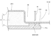
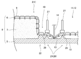
- FIG. 2 is a partial enlarged cross-sectional view of a portion that becomes a core material exposed portion of FIG.
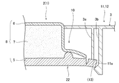
- FIG. 3 is a partially enlarged cross-sectional view similar to FIG. 2, showing a state where the accessory part is attached to FIG. 2.
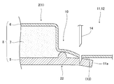
- FIG. 4 is a partially enlarged cross-sectional view similar to FIG. 3 according to a modification of Example 1;
- FIG. 3 is a partially enlarged cross-sectional view similar to FIG. 2 in a case where no cutting auxiliary part is provided. It is an operation
- FIG. 8 is an operation diagram subsequent to FIG. 7, showing a state in which an accessory is attached. It is a partial expanded sectional view of the part concerning Example 2 used as the core material exposure part of FIG. It is the elements on larger scale of FIG.
- FIG. 10 is a partially enlarged cross-sectional view similar to FIG. 9 according to a modified example of the second embodiment. FIG. 10 is a partially enlarged cross-sectional view similar to FIG. 9 in a case where no cutting auxiliary part is provided. It is an operation
- FIG. 1 to FIG. 15 are for explaining each example of the embodiment and its modifications.
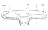
- FIG. 1 is a diagram common to each embodiment
- FIGS. 2 to 8 are diagrams related to the first embodiment
- FIGS. 9 to 15 are diagrams related to the second embodiment.
- a vehicle interior part 2 such as an instrument panel 1 is installed in a front part of a vehicle interior in a vehicle such as an automobile.
- the accessory part 3 (refer FIG. 3) comprised as another member with respect to such an instrument panel 1, for example, a ventilator grill, a decoration panel, etc. is attached.
- These accessory parts 3 are attached later to an opening 11 and a recess 12 formed in advance at predetermined positions of the instrument panel 1.
- various similar vehicle interior parts 2 such as a console box are installed in the vehicle interior.
- the above-described vehicle interior part 2 is integrated by interposing a foam layer 7 having cushioning properties between the hard core material 5 and the soft skin material 6.
- the multilayer component 8 is used.
- an opening / recess formation planned portion 10 that does not have the foam layer 7 with respect to the portion where the opening 11 or recess 12 is formed during foam molding, for example, a core Opening / recessed portion in which the thickness of the foamed layer 7 where the opening 11 and the recessed portion 12 are formed is made thinner than other portions at the time of forming the two-layer laminated portion of the material 5 and the skin material 6 or foaming.
- the core material exposed portion 13 (by processing the inner portion of the opening / recess formation planned portion 10 with a cutting tool 14 such as a hot blade as described later, etc. For example, see FIG. Then, the accessory part 3 described above is attached using the core material exposed portion 13.
- the opening 11 when the opening 11 is formed, first, a two-layer laminated portion of the core material 5 and the skin material 6 inside the opening / recessed formation portion 10, or the core material 5, the foam layer 7, The three-layer laminated portion of the skin material 6 is punched out by using a cutting tool 14 such as a hot blade at the cutting position 15 in FIG. Opening 11a is formed. Thereafter, only the core material 5 is cut using a cutting tool 14 such as a hot blade at a position between the outside of the peripheral edge of the core material opening 11a and the inside of the peripheral edge of the opening / recessed portion 10 to be formed. By trimming the skin material 6 and the foamed layer 7 so as to leave the core material, the core material exposed portion 13 is formed around the core material opening portion 11a as shown in FIG.
- a skin material 6 () is formed so that only the core material 5 is left using a cutting tool 14 such as a hot blade at a position inside the opening / recess formation planned portion 10 described above after foam molding.
- the core material exposed portion 13 is formed by trimming a sewing line portion 9 and the like.
- the “core material 5” described above is made of hard resin.
- the core material 5 is formed to have a constant thickness except for exceptional portions.
- the “skin material 6” described above is made of a soft resin.
- the skin material 6 is formed to have a constant thickness except for exceptional portions.
- the above “foam layer 7” can also be referred to as a cushion layer.
- the foam layer 7 is formed to have a constant thickness except for exceptional portions.
- a foaming liquid as a raw material for the foamed layer 7 is injected between a mold of a foam molding apparatus (not shown), that is, between the core material 5 and the skin material 6 set in the foam molding die. And it is manufactured by foaming a foaming liquid in the foaming mold to form the foamed layer 7.
- the foaming liquid is obtained by adding a foaming liquid agent to a stock solution that is a raw material of the foaming layer 7 and adjusting the concentration so as to obtain a required expansion ratio.
- the multilayer component 8 is formed to have a constant thickness except for exceptional portions.
- the above-described “opening / recessed portion forming portion 10” is as follows. First, on the surface of the core material 5, that is, on the surface on the skin material 6 side, a protrusion 22 serving as a blocking portion is projected in a loop shape along the shape of the opening / recess formation planned portion 10. In the foam molding, the skin material 6 is pressed against the ridge 22 to seal the foamed liquid so as not to enter the loop-shaped ridge 22. On the other hand, the above-described skin material 6 is preliminarily shaped with a concave-shaped portion having a depth substantially equal to the thickness of the multilayer component 8 in advance on the portion corresponding to the loop-shaped protruding portion 22 before foam molding. Try to keep it.
- the thickness of the outer portion of the opening / recess formation planned portion 10 becomes equal to that of the other portions of the multilayer component 8, and the core material 5 is formed on the inner portion of the opening / recess formation planned portion 10. It will be in the state covered by. At this time, for example, the core material 5 and the skin material 6 are separated from each other without being bonded by the foamed layer 7 inside the loop-shaped protrusion 22.
- a primer such as a primer for improving the adhesion between the core material 5 and the foamed layer 7 may be applied to the outer portion of the loop-shaped protrusion 22 in the core material 5. good.
- the above-described “core material exposed portion 13” is, for example, when the opening 11 or the recess 12 for attaching the accessory 3 is formed on the multilayer component 8, for example, the attachment standard of the accessory 3, that is, In order to use it as a reference for surface matching, an attachment portion, etc., it is provided by trimming the skin material 6 inside the opening / recess formation planned portion 10.
- an air outlet member such as a ventilator grill as described above is attached to the opening 11 as the accessory 3.
- a decorative panel such as a finisher or a decorative part such as an emblem as described above is fitted in the recess 12 as the accessory part 3. As shown in FIG.
- a support portion 3 a or a positioning portion that is supported against the surface of the core material exposed portion 13 or a core material.
- a claw portion 3b that can be locked to the back surface of the core material exposed portion 13 through the opening portion 11a is appropriately provided.
- the above-mentioned “cutting tool 14” is, for example, the above-described hot blade.
- the cutting tool is heated with a heater so that the resin part can be easily cut.
- FIG. 1 and FIGS. 2 to 8 are for explaining an example of this embodiment and its modifications.
- the core material 5 protrudes toward the skin material 6 side (see FIG. 2) or the anti-skin material 6 side (see FIG. 4) at the portion where the skin material 6 is cut, and assists the cutting with the cutting tool 14.
- An auxiliary cutting part 21 is provided.
- the above-mentioned “part where the skin material 6 is cut” refers to a part where the skin material 6 is trimmed to form the core material exposed portion 13.
- the above-mentioned “skin material 6 side or anti-skin material 6 side” can be at least one or both. In this case, it is either one.
- the above-described “cutting auxiliary portion 21” is provided as a skin cutting auxiliary portion for assisting the cutting of the skin material 6.
- the auxiliary cutting portion 21 is a tool receiving portion 25 that directly receives the cutting tool 14.
- the tool receiving portion 25 is formed integrally with the core material 5.
- the tool receiving portion 25 is formed to have a height that takes into account the dent that the cutting tool 14 bites into, i.e., the portion of the wall thickness that has been cut, so that the skin material 6 After the cutting, a portion having a thickness equal to or larger than the constant thickness of the core material 5 is left in the portion of the core material 5 where the auxiliary cutting portion 21 is provided.
- the top portion of the tool receiving portion 25 is a flat surface parallel to the surface of the core material 5 so that the cutting tool 14 can be reliably received.
- the cutting auxiliary portion 21 is formed so as to protrude toward the skin material 6 side. Further, the cutting auxiliary portion 21 may be formed separately from the ridge portion 22, but in this case, the cutting auxiliary portion 21 is formed integrally with the ridge portion 22 to simplify the structure. It tries to make it. In the case of FIG. 4, as described above, the cutting auxiliary portion 21 is formed so as to protrude toward the anti-skin material 6 side. The auxiliary cutting portion 21 is formed separately from the protruding portion 22.
- the multilayer component 8 is the vehicle interior component 2.
- the above-mentioned “vehioned “vehicle interior part 2” is stored in the instrument panel 1 provided in the front part of the vehicle interior of the vehicle, a glove box provided in the passenger seat side portion of the instrument panel 1, or the like. It can be a box lid portion of the apparatus.
- the multilayer component 8 can be used other than the instrument panel 1 and the box lid portion of the glove box.
- a cutting auxiliary portion 21 that protrudes toward the skin material 6 or the anti-skin material 6 is provided at a portion of the core material 5 where the skin material 6 is cut.
- the cutting auxiliary part 21 can assist the cutting of the skin material 6 by the cutting tool 14.
- the cutting auxiliary portion 21 can ensure the necessary strength for the core member 5 portion.
- the accessory part 3 is attached to the core material exposure part 13, it can prevent that the shift
- a hot blade or the like when trimming the outer portion of the peripheral portion of the opening 11, a hot blade or the like is used. Since it is difficult to accurately cut only the skin material 6 with the cutting tool 14, the cutting tool 14 such as a hot blade bites into the core material 5, that is, the necessary thickness of the core material 5 together with the skin material 6. There is a high risk of cutting a part of. In this way, when a part of the thickness of the core material 5 is cut, as shown in FIG. 8, the part of the thickness of the core material 5 is partially cut when the accessory part 3 is attached. As a result of deformation, a misalignment occurs on the mating surface with the accessory part 3.
- the multilayer component 8 is the vehicle interior component 2, the multilayer component 8 installed in the vehicle can be easily formed.
- FIG. 1 and FIGS. 9 to 15 are for explaining an example of this embodiment and its modifications.
- a sewing line portion 9 formed by sewing with a sewing machine or the like is provided on the above-described skin material 6 in order to produce a high-class feeling. For example, it looks like a leather sticking tone.
- a polyester sewing thread or the like is used for the above-mentioned “sewing line portion 9 or stitch portion”.
- This polyester sewing thread is resistant to heat and is very strong because it is formed by twisting a large number of fine threads. Simply by pressing a cutting tool 14 such as a hot blade, It is very difficult to cut.
- the sewing line portion 9 is provided on the skin material 6 so as to pass through the position of the core material exposed portion 13. When the core material exposed portion 13 is formed, it is necessary to trim the skin material 6 together with the sewing line portion 9.
- the core material 5 protrudes toward the skin material 6 side or the anti-skin material 6 side at a portion where the sewing line portion 9 formed on the skin material 6 is cut, and a cutting tool 14.
- a cutting assisting portion 21 for assisting the cutting of the sewing line portion 9 is provided.
- the above-mentioned “skin material 6 side or anti-skin material 6 side” can be at least one or both. In this case, it is either one, especially the skin material 6 side.
- the above-mentioned “cutting auxiliary portion 21” is provided as a skin material and a sewing line cutting auxiliary portion for assisting the cutting of the skin material and the sewing wire portion 9. The cutting auxiliary portion 21 will be described later.
- disconnection of this Example or the auxiliary
- the cutting auxiliary portion 21 or the sewing line cutting auxiliary portion of this embodiment may be provided separately from the cutting auxiliary portion 21 or the skin cutting auxiliary portion of the first embodiment.
- the cutting auxiliary portion 21 is provided at a position facing the cutting tool 14 and serves as a tool receiving portion 25 that directly receives the cutting tool 14.
- the above-mentioned “tool receiving portion 25” is a recess formed by the cutting tool 14 biting in when the sewing wire portion 9 is cut by the cutting tool 14, that is, a portion obtained by cutting a part of the wall thickness. It protrudes toward the skin material 6 side from the part which becomes the core material exposure part 13 so that it may become the height dimension which considered this part. And after cut
- the tool receiving portion 25 is formed integrally with the core material 5. In this case, the top portion of the tool receiving portion 25 is a flat surface parallel to the surface of the core material 5 so that the cutting tool 14 can be reliably received.
- the auxiliary cutting part 21 is provided on both sides of the position facing the cutting tool 14, and the sewing line part 9 is connected to the external sewing line pressing holder 27.
- a pair of sewing wire pinching cradle cradle pedestals 28 capable of pinching and holding the two positions on both sides of the cutting position.
- At least one of the sewing wire pinching supports 28 has a non-slip processing portion 29 that can prevent the skin material 6 or the sewing wire portion 9 from slipping.
- the above-mentioned “external sewing line pressing holder 27” is a clamp device that presses at least the periphery of the sewing line portion 9 of the skin material 6 when the skin material 6 is cut.
- the above-described "sewing line pinning cradle 28" has a shape and a size suitable for pressing with the above-described clamping device.
- the distance between the pair of sewing wire pinning receiving bases 28 is the same as or slightly wider than the distance at which the cutting tool 14 can be inserted.
- the sewing wire pinching cradle 28 protrudes from the portion that becomes the core material exposed portion 13 toward the skin material 6 side.
- the sewing wire pinching cradle 28 is formed integrally with the core material 5.
- non-slip processing portion 29 is a fine uneven shape portion formed on the surface of the sewing wire pinching cradle 28, an anti-slip member attached to the surface of the sewing wire pinching cradle 28, or the like. be able to.
- the anti-slip portion 29 is formed by sharpening the tip of the sewing wire pinching cradle 28.
- the multilayer component 8 is the vehicle interior component 2.
- a cutting auxiliary portion 21 projecting toward the skin material 6 side or the anti-skin material 6 side is provided at a portion of the core material 5 where the sewing line portion 9 formed on the skin material 6 is cut.
- the cutting auxiliary part 21 can assist the cutting of the sewing wire part 9 by the cutting tool 14. Therefore, even if the sewing line portion 9 is difficult to cut, the sewing wire portion 9 may be cut poorly, or the core material exposed portion 13 may be recessed and thinned by the cutting tool 14, and the core material exposed portion 13 may be thinned. It can prevent that the intensity
- the auxiliary cutting part 21 is a tool receiving part 25 provided at a position facing the cutting tool 14.
- the tool receiving portion 25 is deformed so as to be recessed when the cutting tool 14 bites in, but the tool receiving portion 25 protrudes from the core material exposed portion 13 in consideration of the size of the recessed portion. Since the thickness can be increased, the basic portion of the core material exposed portion 13 can be prevented from being dented and thinned, and the strength reduction of the core material exposed portion 13 can be prevented.
- the cutting auxiliary portion 21 is a pair of sewing wire pinching bases 28 provided on both sides of a position facing the cutting tool 14.
- the two positions on both sides of the cutting position of the sewing line portion 9 are clamped and held between the pair of sewing line sandwiching receiving bases 28 and the external sewing line pressing holder 27, and the sewing line portion 9.
- a tension necessary for cutting can be applied. Therefore, the skin material 6 and the sewing line portion 9 can be reliably cut by the cutting tool 14.
- the sewing line portion 9 can be cut in a state of floating from the core material exposed portion 13, the basic portion of the core material exposed portion 13 can be prevented from being dented and thinned.
- the skin material 6 and the sewing wire portion 9 can be sewn together with the sewing wire pinching cradle 28 and the sewing line pressing and holding tool 27 when cutting. It is possible to prevent the above-described tension from being lowered.
- the multilayer component 8 is the vehicle interior component 2, the multilayer component 8 having the sewing wire portion 9 installed in the vehicle can be easily formed.
Landscapes
- Engineering & Computer Science (AREA)
- Mechanical Engineering (AREA)
- Casting Or Compression Moulding Of Plastics Or The Like (AREA)
- Molding Of Porous Articles (AREA)
- Laminated Bodies (AREA)
- Vehicle Interior And Exterior Ornaments, Soundproofing, And Insulation (AREA)
- Instrument Panels (AREA)
Abstract
La présente invention permet de réaliser une découpe appropriée principalement d'une matière de revêtement de surface, etc. La présente invention propose une partie multicouche (8) obtenue en intercalant une couche de mousse (7) entre un matériau de noyau dur (5) et un matériau de revêtement de surface souple (6) et en unifiant celles-ci, et concerne une structure de la partie multicouche (8), dans laquelle le matériau de noyau (5) présente une section matériau de noyau apparente (13) et la section matériau de noyau apparente (13) est obtenue en découpant et en retirant le matériau de revêtement de surface (6). La zone du matériau de noyau (5) dans laquelle le matériau de revêtement de surface (6) doit être découpé est pourvue d'une section aide à la découpe (21), qui fait saillie sur le côté du matériau de revêtement de surface (6) ou le côté opposé au matériau de revêtement de surface (6) et facilite la découpe par un outil de coupe (14).
Priority Applications (1)
| Application Number | Priority Date | Filing Date | Title |
|---|---|---|---|
| US14/770,518 US20160009053A1 (en) | 2013-02-27 | 2014-02-24 | Structure of multilayer component |
Applications Claiming Priority (4)
| Application Number | Priority Date | Filing Date | Title |
|---|---|---|---|
| JP2013036836 | 2013-02-27 | ||
| JP2013-036836 | 2013-02-27 | ||
| JP2013139711A JP6033173B2 (ja) | 2013-02-27 | 2013-07-03 | 多層部品構造 |
| JP2013-139711 | 2013-07-03 |
Publications (1)
| Publication Number | Publication Date |
|---|---|
| WO2014132910A1 true WO2014132910A1 (fr) | 2014-09-04 |
Family
ID=51428175
Family Applications (1)
| Application Number | Title | Priority Date | Filing Date |
|---|---|---|---|
| PCT/JP2014/054285 Ceased WO2014132910A1 (fr) | 2013-02-27 | 2014-02-24 | Structure de partie multicouche |
Country Status (3)
| Country | Link |
|---|---|
| US (1) | US20160009053A1 (fr) |
| JP (1) | JP6033173B2 (fr) |
| WO (1) | WO2014132910A1 (fr) |
Citations (7)
| Publication number | Priority date | Publication date | Assignee | Title |
|---|---|---|---|---|
| JPS60166420A (ja) * | 1984-02-10 | 1985-08-29 | Mazda Motor Corp | 自動車の合成樹脂製内装材の製造方法 |
| JPH02197443A (ja) * | 1989-01-26 | 1990-08-06 | Mitsubishi Motors Corp | 自動車用内装品及びその成形方法 |
| JPH02299809A (ja) * | 1989-05-16 | 1990-12-12 | Nissan Motor Co Ltd | 装飾部材成形方法 |
| JPH0417934U (fr) * | 1990-06-07 | 1992-02-14 | ||
| JPH04223111A (ja) * | 1990-12-26 | 1992-08-13 | Nishikawa Kasei Co Ltd | 部品一体発泡成形方法 |
| JP2002137235A (ja) * | 2000-08-25 | 2002-05-14 | Nishikawa Kasei Co Ltd | 表皮材付成形体の開口部形成方法 |
| JP2004154896A (ja) * | 2002-11-06 | 2004-06-03 | Inoac Corp | 発泡積層体 |
Family Cites Families (2)
| Publication number | Priority date | Publication date | Assignee | Title |
|---|---|---|---|---|
| JPH037326A (ja) * | 1989-06-03 | 1991-01-14 | Honda Motor Co Ltd | 表皮材を有する発泡成形品の製造方法 |
| JP3707319B2 (ja) * | 1999-11-12 | 2005-10-19 | 株式会社イノアックコーポレーション | フロアコンソール |
-
2013
- 2013-07-03 JP JP2013139711A patent/JP6033173B2/ja not_active Expired - Fee Related
-
2014
- 2014-02-24 US US14/770,518 patent/US20160009053A1/en not_active Abandoned
- 2014-02-24 WO PCT/JP2014/054285 patent/WO2014132910A1/fr not_active Ceased
Patent Citations (7)
| Publication number | Priority date | Publication date | Assignee | Title |
|---|---|---|---|---|
| JPS60166420A (ja) * | 1984-02-10 | 1985-08-29 | Mazda Motor Corp | 自動車の合成樹脂製内装材の製造方法 |
| JPH02197443A (ja) * | 1989-01-26 | 1990-08-06 | Mitsubishi Motors Corp | 自動車用内装品及びその成形方法 |
| JPH02299809A (ja) * | 1989-05-16 | 1990-12-12 | Nissan Motor Co Ltd | 装飾部材成形方法 |
| JPH0417934U (fr) * | 1990-06-07 | 1992-02-14 | ||
| JPH04223111A (ja) * | 1990-12-26 | 1992-08-13 | Nishikawa Kasei Co Ltd | 部品一体発泡成形方法 |
| JP2002137235A (ja) * | 2000-08-25 | 2002-05-14 | Nishikawa Kasei Co Ltd | 表皮材付成形体の開口部形成方法 |
| JP2004154896A (ja) * | 2002-11-06 | 2004-06-03 | Inoac Corp | 発泡積層体 |
Also Published As
| Publication number | Publication date |
|---|---|
| JP6033173B2 (ja) | 2016-11-30 |
| US20160009053A1 (en) | 2016-01-14 |
| JP2014193595A (ja) | 2014-10-09 |
Similar Documents
| Publication | Publication Date | Title |
|---|---|---|
| CN106232316B (zh) | 用于汽车内饰配件的多层模制体和生产这种模制体的方法 | |
| CN116323168A (zh) | 具有模制泡沫背衬的面板组件 | |
| US7100958B2 (en) | Trim element, especially for the interior of a motor vehicle, and a method for the manufacture thereof | |
| US20070193673A1 (en) | Vehicular interior parts and manufacturing method thereof | |
| KR101773138B1 (ko) | 차량용 내장재 제조방법 | |
| BRPI0712615A2 (pt) | artigo moldado incluindo elemento decorativo e método de unir um elemento decorativo a um componente de veìculo | |
| US10081277B2 (en) | Trim cover and seat part | |
| JP6588559B2 (ja) | バックボード取り付け構造及び乗り物用シート | |
| JP2009055928A (ja) | 車両用表皮一体発泡成形シート | |
| US20190322072A1 (en) | Layered body and method for producing same | |
| JP2005053435A (ja) | 加飾部品並びに自動車用内装部品 | |
| CN114746252A (zh) | 层叠成形体及其制造方法 | |
| US6663734B2 (en) | Method for forming a foamed product integral with trim cover assembly | |
| JP6335317B2 (ja) | 自動車用シート及び自動車用シートの製造方法 | |
| EP2153969A1 (fr) | Moule et procédé de fabrication d'un panneau de garniture | |
| US12172585B2 (en) | Multiple-part surface covering for the cladding of support structures and cladding part | |
| JP2008022982A (ja) | 車両用シートパッド及びその製造方法 | |
| US20170114485A1 (en) | Method of sewing process for trim cover of vehicle seat and vehicle seat using same | |
| JP6033173B2 (ja) | 多層部品構造 | |
| JP5985240B2 (ja) | 車両用内装材の基材、それを用いた内装材、および車両用内装材の製造方法 | |
| JP6198619B2 (ja) | バックパッド及びバックパッド用裏面材 | |
| JP2010052537A (ja) | 表皮材、および内装品 | |
| US10500810B2 (en) | Decorative covering material with alignment features | |
| JP4253261B2 (ja) | 車両の内装パネル及びその製造方法 | |
| JP3707319B2 (ja) | フロアコンソール |
Legal Events
| Date | Code | Title | Description |
|---|---|---|---|
| 121 | Ep: the epo has been informed by wipo that ep was designated in this application |
Ref document number: 14757691 Country of ref document: EP Kind code of ref document: A1 |
|
| WWE | Wipo information: entry into national phase |
Ref document number: 14770518 Country of ref document: US |
|
| NENP | Non-entry into the national phase |
Ref country code: DE |
|
| 122 | Ep: pct application non-entry in european phase |
Ref document number: 14757691 Country of ref document: EP Kind code of ref document: A1 |