WO2014147913A1 - Modèle gonflable - Google Patents
Modèle gonflable Download PDFInfo
- Publication number
- WO2014147913A1 WO2014147913A1 PCT/JP2013/083882 JP2013083882W WO2014147913A1 WO 2014147913 A1 WO2014147913 A1 WO 2014147913A1 JP 2013083882 W JP2013083882 W JP 2013083882W WO 2014147913 A1 WO2014147913 A1 WO 2014147913A1
- Authority
- WO
- WIPO (PCT)
- Prior art keywords
- bag
- air injection
- model according
- mannequin
- air
- Prior art date
- Legal status (The legal status is an assumption and is not a legal conclusion. Google has not performed a legal analysis and makes no representation as to the accuracy of the status listed.)
- Ceased
Links
Images




Classifications
-
- G—PHYSICS
- G09—EDUCATION; CRYPTOGRAPHY; DISPLAY; ADVERTISING; SEALS
- G09B—EDUCATIONAL OR DEMONSTRATION APPLIANCES; APPLIANCES FOR TEACHING, OR COMMUNICATING WITH, THE BLIND, DEAF OR MUTE; MODELS; PLANETARIA; GLOBES; MAPS; DIAGRAMS
- G09B23/00—Models for scientific, medical, or mathematical purposes, e.g. full-sized devices for demonstration purposes
-
- A—HUMAN NECESSITIES
- A63—SPORTS; GAMES; AMUSEMENTS
- A63H—TOYS, e.g. TOPS, DOLLS, HOOPS OR BUILDING BLOCKS
- A63H3/00—Dolls
- A63H3/06—Air-filled or inflatable toy figures
-
- A—HUMAN NECESSITIES
- A63—SPORTS; GAMES; AMUSEMENTS
- A63B—APPARATUS FOR PHYSICAL TRAINING, GYMNASTICS, SWIMMING, CLIMBING, OR FENCING; BALL GAMES; TRAINING EQUIPMENT
- A63B69/00—Training appliances or apparatus for special sports
- A63B69/0002—Training appliances or apparatus for special sports for baseball
-
- G—PHYSICS
- G01—MEASURING; TESTING
- G01M—TESTING STATIC OR DYNAMIC BALANCE OF MACHINES OR STRUCTURES; TESTING OF STRUCTURES OR APPARATUS, NOT OTHERWISE PROVIDED FOR
- G01M17/00—Testing of vehicles
- G01M17/007—Wheeled or endless-tracked vehicles
-
- A—HUMAN NECESSITIES
- A47—FURNITURE; DOMESTIC ARTICLES OR APPLIANCES; COFFEE MILLS; SPICE MILLS; SUCTION CLEANERS IN GENERAL
- A47F—SPECIAL FURNITURE, FITTINGS, OR ACCESSORIES FOR SHOPS, STOREHOUSES, BARS, RESTAURANTS OR THE LIKE; PAYING COUNTERS
- A47F8/00—Dummies, busts or the like, e.g. for displaying garments
-
- A—HUMAN NECESSITIES
- A63—SPORTS; GAMES; AMUSEMENTS
- A63B—APPARATUS FOR PHYSICAL TRAINING, GYMNASTICS, SWIMMING, CLIMBING, OR FENCING; BALL GAMES; TRAINING EQUIPMENT
- A63B69/00—Training appliances or apparatus for special sports
- A63B69/0002—Training appliances or apparatus for special sports for baseball
- A63B2069/0004—Training appliances or apparatus for special sports for baseball specially adapted for particular training aspects
- A63B2069/0006—Training appliances or apparatus for special sports for baseball specially adapted for particular training aspects for pitching
-
- A—HUMAN NECESSITIES
- A63—SPORTS; GAMES; AMUSEMENTS
- A63B—APPARATUS FOR PHYSICAL TRAINING, GYMNASTICS, SWIMMING, CLIMBING, OR FENCING; BALL GAMES; TRAINING EQUIPMENT
- A63B2225/00—Miscellaneous features of sport apparatus, devices or equipment
- A63B2225/62—Inflatable
-
- A—HUMAN NECESSITIES
- A63—SPORTS; GAMES; AMUSEMENTS
- A63B—APPARATUS FOR PHYSICAL TRAINING, GYMNASTICS, SWIMMING, CLIMBING, OR FENCING; BALL GAMES; TRAINING EQUIPMENT
- A63B2243/00—Specific ball sports not provided for in A63B2102/00 - A63B2102/38
- A63B2243/0025—Football
-
- A—HUMAN NECESSITIES
- A63—SPORTS; GAMES; AMUSEMENTS
- A63B—APPARATUS FOR PHYSICAL TRAINING, GYMNASTICS, SWIMMING, CLIMBING, OR FENCING; BALL GAMES; TRAINING EQUIPMENT
- A63B2243/00—Specific ball sports not provided for in A63B2102/00 - A63B2102/38
- A63B2243/0037—Basketball
-
- G—PHYSICS
- G09—EDUCATION; CRYPTOGRAPHY; DISPLAY; ADVERTISING; SEALS
- G09B—EDUCATIONAL OR DEMONSTRATION APPLIANCES; APPLIANCES FOR TEACHING, OR COMMUNICATING WITH, THE BLIND, DEAF OR MUTE; MODELS; PLANETARIA; GLOBES; MAPS; DIAGRAMS
- G09B25/00—Models for purposes not provided for in G09B23/00, e.g. full-sized devices for demonstration purposes
Definitions
- the present invention relates to an air injection model.
- an obstacle for example, a mannequin doll
- the collision avoidance ability of the automatic brake device is examined. The collision avoidance performance test is repeated.
- the conventional mannequin doll is made of a hard material, in the collision avoidance performance test, if the vehicle collides with the mannequin doll (collision event), the vehicle or mannequin doll is damaged. End up. Further, in order to perform a future collision avoidance performance test, it is necessary to perform repair work for each of the vehicle and the mannequin doll or to prepare a large number of alternatives. As described above, the collision avoidance performance test requires a lot of work and time.
- the present invention intends to provide an air injection type model that simplifies the collision avoidance performance test.
- the present invention is an air-injection model comprising a bag having airtightness formed by joining a plurality of sheets, and having a shape imitating a human body by injecting gas into the bag and expanding the bag.
- the standing posture maintaining tool for maintaining the standing posture of the bag is provided, and the standing posture maintaining tool has an engaging portion provided on the bag and engageable with a locking member.
- a partition member that forms an airtight space in which the lower body bag portion simulating the lower body is independent of other portions. Moreover, it is preferable that the said engaging part is located above the said partition member.
- the posture of the portion below the engaging portion in the bag is changed between the first state and the second state. It is preferable to make it switchable.
- the said bag is formed with the recessed part dented toward an inner side, and it is preferable that the said recessed part is located between the said engaging part and the lower end of the said bag. Furthermore, it is preferable that the said recessed part was formed in the knee part, the crotch part, or the ankle part.
- a branch portion is formed in the bag, and a concave portion that is recessed upward is formed in the branch portion. Moreover, it is preferable that the said branch part is located in a hip joint part.
- the bag includes a first bag portion, a second bag portion, and an attachment / detachment mechanism for detachably attaching the second bag portion to the first bag portion.
- the said attachment / detachment mechanism has the 1st surface fastener provided in the said 1st bag part, and the 2nd surface fastener provided in the said 2nd bag part.
- the collision avoidance performance test can be simplified.
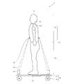
- FIG. 1 It is a side view which shows the outline
- (A) is an exploded view which shows the outline
- B) is a front view showing an outline of the second air injection type mannequin. It is a front view which shows the outline
- the obstacle mounting device 2 is used for a collision avoidance performance test.
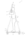
- the obstacle mounting device 2 is provided with an obstacle, that is, a carriage 20 on which an air injection mannequin 10 is mounted, And an upright posture maintenance tool 30 for maintaining the upright posture of the injection type mannequin 10.
- the air injection type mannequin 10 and the standing posture maintenance tool 30 constitute an air injection type model.
- the carriage 20 includes a mounting plate 21 on which the air injection mannequin 10 is mounted and a wheel 22 attached to the lower surface of the mounting plate 21.
- the standing posture maintenance tool 30 has a bottom plate 31 attached to the bottom of the air injection manikin 10, and maintains the standing posture of the air injection mannequin 10 on the carriage 20 by the bottom surface of the bottom plate 31.
- the standing posture maintaining tool 30 includes a cart side locking ring 32 provided on the cart 20, an obstacle side locking ring 33 provided on the air injection type mannequin 10, a cart side locking ring 32, and an obstacle. It has the string 34 which ties the side latching ring 33. By connecting the cart side locking ring 32 and the obstacle side locking ring 33 using the string 34, the air injection type mannequin 10 and the cart 20 can be locked. In this way, the cart side locking ring 32, the obstacle side locking ring 33 and the string 34 are integrated to maintain the standing posture of the air injection mannequin 10 on the cart 20.
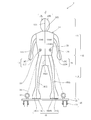
- the air-injection mannequin 10 is formed in a sealed bag shape by joining a plurality of sheets, and includes a partition plate 10A that divides its own internal space into two.
- the partition plate 10 ⁇ / b> A extends from the front side to the back side inside the air injection type mannequin 10.
- the partition plate 10A the air-injection mannequin 10 is divided into an upper body portion 11 on the upper side of the partition plate 10A and a lower body portion 18 on the lower side of the partition plate 10A.
- the sheet and partition plate 10A constituting the air injection type mannequin 10 are made of an elastic material.
- the elastic material include plastic, and examples of the plastic include vinyl, that is, polyvinyl chloride (PVC), polypropylene, and the like.
- PVC polyvinyl chloride
- These sheets and the partition plate 10A are formed in a sealed bag shape by the joining of the high-frequency joining means.
- the test vehicle used for the collision avoidance performance test is equipped with an obstacle detection device (for example, a millimeter wave radar) that detects an obstacle together with an automatic brake device.
- an obstacle detection device for example, a millimeter wave radar
- seat and partition plate 10A which comprise the air injection type mannequin 10 do not contain a metal. That is, it is preferable that the sheet
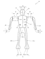
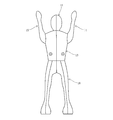
- the upper body 11 includes a head 12 shaped like a head, a trunk 13 shaped like a torso, a left arm 14 shaped like a left arm, and a shape like a right arm.
- the head 12 includes a left head sheet 12L that forms the left side of the head and a right head sheet 12R that forms the right side of the head.
- the left head sheet 12L and the right head sheet 12R are joined to each other by a head joining line 12S extending from the front surface of the head to the back surface of the head via the top.
- the torso 13 includes a front left torso sheet 13FL that forms the front left side of the torso, a front right torso sheet 13FR that forms the front right side of the torso, a back left torso sheet 13BL that forms the back left side of the torso, and the back of the torso And a back right trunk sheet 13BR forming the right side.
- the front left trunk sheet 13FL and the front right trunk sheet 13FR are joined to each other by a front trunk joining line 13FS extending in the vertical direction on the front surface of the trunk.
- the back left torso sheet 13BL and the back right torso sheet 13BR are joined to each other by a back trunk joining line 13BS extending in the vertical direction on the back surface of the trunk.
- the front left torso sheet 13FL and the back left torso sheet 13BL, and the front right torso sheet 13FR and the back right torso sheet 13BR are respectively connected by side joint lines 13SS (see FIG. 6) extending in the vertical direction on the side surfaces of the torso. Are joined together.
- the head 12 is directly joined to the body 13 by a head-to-body joining line 12X.
- the head portion 12 and the trunk portion 13 constitute one sealed bag.
- the left arm portion 14 includes a left arm inner sheet 14N that forms the inside of the left arm and a left arm outer sheet 14G that forms the outside of the left arm.
- the left arm inner sheet 14N and the left arm outer sheet 14G are joined to each other by a left arm joining line 14S extending from the front surface of the left arm to the back surface via the hand.
- the right arm portion 15 includes a right arm inner sheet 15N that forms the inner side of the right arm and a right arm outer sheet 15G that forms the outer side of the right arm.
- the right arm inner sheet 15N and the right arm outer sheet 15G are joined to each other by a right arm joining line 15S extending from the front surface of the right arm to the back surface via the hand. In this way, the left arm portion 14 becomes one sealed bag by the respective sheets 14N and 14G, and the right arm portion 15 becomes one hermetic bag by the respective sheets 15N and 15G.
- the coupling mechanism 16 includes a trunk side coupling tool 16 ⁇ / b> D provided at the shoulder portion of the trunk portion 13, and an arm side coupling tool 16 ⁇ / b> U provided at the base portion of the left arm portion 14 and the right arm portion 15. And having.
- the trunk side connector 16D and the arm side connector 16U are so-called hook-and-loop fasteners, and can be detachably connected to each other.
- the lower body part 18 is integrally formed from the waist to the tip of both feet, and forms the left outer lower body sheet 18LG that forms the outside of the left part and the inside of the left part. It has a left inner lower body sheet 18LN, a right outer lower body sheet 18RG that forms the outside of the right part, and a right inner lower body sheet 18RN that forms the inside of the right part.
- the left inner lower body sheet 18LN and the right inner lower body sheet 18RN are joined to each other by a crotch joint line 18SS that extends from the front center of the waist to the center of the back of the waist via the crotch.
- the left outer lower body sheet 18LG and the left inner lower body sheet 18LN are joined to each other by a left leg joint line 18LS extending from the front of the waist to the back of the waist via the tip of the foot.
- the right outer lower body sheet 18RG and the right inner lower body sheet 18RN are joined to each other by a right leg joining line 18RS extending from the front of the waist to the back of the waist via the tip of the foot.
- the lower body part 18 becomes one sealed bag by the sheets 18LG, 18LN, 18RG, 18RN.
- the obstacle mounting device 2 is arranged in advance on the traveling course of the vehicle, or when the vehicle approaches, the obstacle mounting device 2 is entered into the traveling course, so that the automatic mounted on the vehicle. Check for braking device operation and collision events.
- the obstacle mounted on the obstacle mounting device 2 is the air injection mannequin 10, even if the vehicle collides with the obstacle, the colliding vehicle or obstacle is not damaged. For this reason, it is not necessary to repair or replace a vehicle or an obstacle that has been performed every time the vehicle collides with an obstacle. Furthermore, since the air injection type mannequin 10 is provided with the obstacle side locking ring 33, for example, using the carriage side locking ring 32 and the string 34 provided on the carriage 20, The injection type mannequin 10 and the carriage 20 can be locked. For this reason, the air-injection-type mannequin 10 in the standing state can be arranged or entered as it is on the traveling course.
- the air injection type mannequin 10 is divided into the upper body part 11 and the lower body part 18 by the partition plate 10A, even if the upper body part 11 is damaged due to a collision or the like, the lower body part 18 can be secured. Therefore, even when the upper body 11 is damaged, even when the upper body cannot be sealed, the upright posture of the inflatable mannequin 10 can be maintained.
- the air injection type mannequin 10 includes the coupling mechanism 16, that is, the trunk side coupling tool 16D and the arm side coupling tool 16U, the left arm part 14 and the right arm with respect to the upper body part 11 as shown in FIGS.
- the part 15 can be mounted in various orientations (360 ° in all directions). As a result, the inflatable mannequin 10 can take various postures.
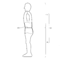
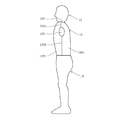
- the knee part projects forward from the crotch part and the ankle part. That is, on the back side of the knee portion of the lower body 18, a first recess 18 HA that is recessed inward is provided. Therefore, when a force from the crotch portion toward the ankle portion is applied to the inflatable mannequin 10, the first recessed portion 18HA preferentially bends, and as a result, the knee portion is relatively stretched (see FIG. 8A). ) And the posture where the knee is bent (see FIG. 8B), the posture of the lower body 18 can be adjusted.
- the locking mechanism 40 is used in combination with the air injection type mannequin 10 to adjust the tightening force of the string 34 connected to the carriage side locking ring 32 and the obstacle side locking ring 33, thereby reducing the air.
- the desired posture of the injection mannequin 10 can be maintained. Furthermore, even in this case, since the air-injection mannequin 10 is divided into the upper body part 11 and the lower body part 18 by the partition plate 10A, even if the posture of the lower body part 18 changes, The shape of the upper body part 11 can be kept constant.
- the obstacle side locking ring 33 is provided above the partition plate 10A, the tightening force by the string 34 is uniformly applied to the entire partition plate 10A. For this reason, even if it is a case where the fastening force by the string 34 is provided, the standing posture can be created while avoiding the distortion of the posture of the lower body 18.
- the 2nd recessed part 18HB recessed toward the inner side is provided in the front side of the ankle part of the lower half body part 18.
- FIG. 8 when a force for pressing the air-injected mannequin 10 from above or a force for pulling downward is applied, the first recessed portion 18HA and the second recessed portion 18HB are bent preferentially, resulting in a posture in which the knee is extended (FIG. 8).
- the posture of the lower body 18 can be adjusted between (see (A)) and the posture in which the knee is bent (see FIG. 8B). *
- the first concave portion 18HA is provided on the back side of the knee portion of the lower body portion 18, but the present invention is not limited to this. If it is between the obstruction side latching ring 33 and the lower end of the air injection type mannequin 10, the 1st recessed part 18HA should just be provided with respect to the desired site
- the second recess 18HB can be provided on the opposite side of the first recess 18HA in a desired portion. Good. Thereby, as a result of bending both the first recess 18HA and the second recess 18HB with priority, various postures of the air injection mannequin 10 can be produced.
- the connecting mechanism 16 that allows the body portion 13 and the left arm portion 14 or the body portion 13 and the right arm portion 15 to be detachable is used.
- the present invention is not limited to this, and an independent sealed bag is used.
- the connection mechanism 16 includes a trunk side connector 16 ⁇ / b> B provided at the neck portion of the trunk portion 13, and a head side connector 16 ⁇ / b> H provided at the base portion of the head 12.
- the trunk side connector 16B and the head side connector 16H are also so-called hook-and-loop fasteners, and can be detachably connected to each other.
- the head 12 can be attached to the body 13 in various directions (360 ° in all directions).
- a connection mechanism that allows both the upper body part 11 and the lower body part 18 that are independent sealed bags to be detachable may be used. With these connection mechanisms, various postures of the air-injection mannequin 10 can be created.
- the left arm portion 14 having a shape with the left arm extended and the right arm portion 15 having a shape with the right arm extended are used, but the present invention is not limited to this.
- it can be used as a batter model to stand at bats during baseball pitching practice, or it can be used as a defender model in soccer or basketball practice (see FIGS. 7 and 9). ).
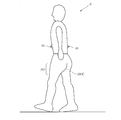
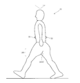
- the air-injection mannequin 10 in the standing posture is used, but the present invention is not limited to this, and the air-injection mannequin 10 in the walking posture (see FIGS. 11A to 11B) may be used.
- the inflatable mannequin 10 in the walking posture a portion where both legs extend from the waist portion, that is, the hip joint portion becomes the branched portion 10B.
- the branch part 10B the upper recessed part 10HC recessed toward upper direction is formed.
- the magnitude of the force from the crotch portion toward the ankle portion is adjusted, and the branch portion 10B is preferentially deformed.
- the hip joint is relatively open (see FIG. 11B).
- a closed posture in which the hip joint is relatively closed see FIG. 11A).
- the obstacle side locking ring 33 is provided in the upper body part 11, but the present invention is not limited to this.
- the obstacle side locking ring 33 may be provided in the lower body part 18.
- the bottom plate 31 as the standing posture maintaining tool 30 may be omitted.
- a mannequin that imitates the shape of a person has been described as an inflatable model, but the present invention is not limited to this, and objects such as vehicles, motorcycles, baseball fences, soccer goals, and the like can be used. It may be a model.
- a device including the air injection mannequin 10, the carriage 20, and the standing posture maintaining tool 30 is used as the obstacle mounting device 2 (see FIG. 1 and the like), but the present invention is not limited to this.
- the air injection type mannequin 10 alone may be used, or only the air injection type mannequin 10 and the standing posture maintaining tool 30 may be used as shown in FIG.
- the standing posture maintaining tool 30 includes an obstacle-side locking ring 33 provided on the air injection type mannequin 10, a ground-side locking tool 38 that can stand on the ground E, and an obstacle-side locking ring 33. And a string 34 for connecting the ground side locking member 38.
- the ground side locking tool 38 includes an engagement ring 38A that can be engaged with the string 34, and a pile 38B that is connected to the engagement ring 38A and can be driven into the ground E. Thereby, the air injection type mannequin 10 can be provided directly on the ground E while maintaining a predetermined posture.
Landscapes
- Physics & Mathematics (AREA)
- General Physics & Mathematics (AREA)
- Engineering & Computer Science (AREA)
- Physical Education & Sports Medicine (AREA)
- General Health & Medical Sciences (AREA)
- Health & Medical Sciences (AREA)
- Computational Mathematics (AREA)
- Mathematical Analysis (AREA)
- Mathematical Optimization (AREA)
- Mathematical Physics (AREA)
- Pure & Applied Mathematics (AREA)
- Business, Economics & Management (AREA)
- Algebra (AREA)
- Educational Administration (AREA)
- Educational Technology (AREA)
- Theoretical Computer Science (AREA)
- Toys (AREA)
Abstract
L'invention concerne un modèle gonflable, qui comprend un mannequin gonflable (10) placé sur un chariot (20), et un outil de maintien de position verticale (30) pour maintenir le mannequin gonflable (10) dans une position verticale sur le chariot (20). L'outil de maintien de position verticale (30) comprend : une bague de verrouillage de chariot (32) disposée sur le chariot (20) ; une bague de verrouillage d'obstacle (33) disposée sur le mannequin gonflable (10) ; et une corde (34) pour raccorder la bague de verrouillage de chariot (32) et la bague de verrouillage d'obstacle (33).
Priority Applications (2)
| Application Number | Priority Date | Filing Date | Title |
|---|---|---|---|
| US14/777,990 US20160042667A1 (en) | 2013-03-21 | 2013-12-18 | Inflatable model |
| EP13878833.6A EP2966636B1 (fr) | 2013-03-21 | 2013-12-18 | Modèle gonflable |
Applications Claiming Priority (2)
| Application Number | Priority Date | Filing Date | Title |
|---|---|---|---|
| JP2013-058443 | 2013-03-21 | ||
| JP2013058443A JP6235220B2 (ja) | 2013-03-21 | 2013-03-21 | 障害物搭載装置、車両の衝突回避性能のテスト方法 |
Publications (1)
| Publication Number | Publication Date |
|---|---|
| WO2014147913A1 true WO2014147913A1 (fr) | 2014-09-25 |
Family
ID=51579623
Family Applications (1)
| Application Number | Title | Priority Date | Filing Date |
|---|---|---|---|
| PCT/JP2013/083882 Ceased WO2014147913A1 (fr) | 2013-03-21 | 2013-12-18 | Modèle gonflable |
Country Status (4)
| Country | Link |
|---|---|
| US (1) | US20160042667A1 (fr) |
| EP (1) | EP2966636B1 (fr) |
| JP (1) | JP6235220B2 (fr) |
| WO (1) | WO2014147913A1 (fr) |
Cited By (1)
| Publication number | Priority date | Publication date | Assignee | Title |
|---|---|---|---|---|
| CN104729819A (zh) * | 2015-02-04 | 2015-06-24 | 南京林业大学 | 一种家具质检用仿生加载垫制作方法 |
Families Citing this family (9)
| Publication number | Priority date | Publication date | Assignee | Title |
|---|---|---|---|---|
| USD790631S1 (en) * | 2014-12-10 | 2017-06-27 | G-Star Raw C.V. | Form for displaying or fitting |
| US9827998B1 (en) * | 2016-12-03 | 2017-11-28 | Dynamic Research, Inc. | System and method for testing crash avoidance technologies |
| JP2021531424A (ja) * | 2018-07-09 | 2021-11-18 | スワイプ ファッション インコーポレイテッド | 形状調整可能なクロマキー互換性のあるマネキンまたはボディスーツ、および関連する3d画像キャプチャ装置 |
| CN111298402B (zh) * | 2018-07-25 | 2021-02-05 | 郑桓立 | 一种篮球对抗转身训练器及使用方法 |
| CN109393870A (zh) * | 2018-11-30 | 2019-03-01 | 何泽熹 | 一种穿戴物试用机器人及其链节结构和环形链条 |
| US10830229B1 (en) | 2019-05-09 | 2020-11-10 | Joseph D. Lurker | Portable inflatable apparatus |
| CN110694250A (zh) * | 2019-09-30 | 2020-01-17 | 张宝健 | 一种踢打摔拿沙袋 |
| US12451028B2 (en) * | 2023-01-16 | 2025-10-21 | Jiangsu Comco Outdoor Products Co., Ltd. | Inflatable hip model |
| EP4468276A1 (fr) * | 2023-05-23 | 2024-11-27 | 4Activesystems GmbH | Système de stabilisation pour mannequin |
Citations (8)
| Publication number | Priority date | Publication date | Assignee | Title |
|---|---|---|---|---|
| JPS5776693U (fr) * | 1980-10-30 | 1982-05-12 | ||
| JPS6020759U (ja) * | 1983-07-15 | 1985-02-13 | 森川 要 | 気嚢マネキン |
| JPH07155478A (ja) * | 1993-12-06 | 1995-06-20 | Bandai Co Ltd | 人形玩具 |
| JPH10177361A (ja) * | 1996-10-18 | 1998-06-30 | Hiroshi Kawazoe | 多目的人形構造 |
| JP2000132130A (ja) * | 1998-10-23 | 2000-05-12 | Chugoku Tent Kogyo Kk | 内照式広告バルーン |
| JP2005258444A (ja) * | 2005-03-10 | 2005-09-22 | Kakimi Yuka Kk | 広告/装飾装置および広告/装飾媒体の設置方法 |
| JP2007062604A (ja) | 2005-08-31 | 2007-03-15 | Toyota Motor Corp | 車両用自動制動装置 |
| JP2009112376A (ja) * | 2007-11-02 | 2009-05-28 | Mind Create Japan Inc | 空気注入式マネキンおよびその製造方法 |
Family Cites Families (9)
| Publication number | Priority date | Publication date | Assignee | Title |
|---|---|---|---|---|
| US1287176A (en) * | 1918-03-05 | 1918-12-10 | William P Armstrong | Exercising device. |
| GB334352A (en) * | 1929-08-02 | 1930-09-04 | Lajos Dorogi | Improvements in rubber toys and other inflatable bodies |
| US4765079A (en) * | 1985-04-03 | 1988-08-23 | Shiro Takahashi | Pneumatic structure |
| DE20106708U1 (de) * | 2001-04-18 | 2001-10-18 | Janke, Tobias, 63808 Haibach | Aufblasbare Plastik mit Beleuchtung |
| US20050130556A1 (en) * | 2001-08-27 | 2005-06-16 | Crowd In A Box, Inc. | Inflatable humanoid forms |
| JP4161925B2 (ja) * | 2004-03-25 | 2008-10-08 | トヨタ自動車株式会社 | 衝突予測装置もしくはその部品のためのダミー装置または検査方法 |
| JP2008039686A (ja) * | 2006-08-09 | 2008-02-21 | Denso Corp | 衝突試験装置 |
| US20100093250A1 (en) * | 2008-10-10 | 2010-04-15 | Shouzeng Gu | Balloon decorational articles |
| AT511217B1 (de) * | 2011-05-18 | 2012-10-15 | 4A Engineering Gmbh | Dummy-objekt, insbesondere zur funktionsüberprüfung von fahrerassistenzsystemen in kraftfahrzeugen |
-
2013
- 2013-03-21 JP JP2013058443A patent/JP6235220B2/ja active Active
- 2013-12-18 WO PCT/JP2013/083882 patent/WO2014147913A1/fr not_active Ceased
- 2013-12-18 EP EP13878833.6A patent/EP2966636B1/fr active Active
- 2013-12-18 US US14/777,990 patent/US20160042667A1/en not_active Abandoned
Patent Citations (8)
| Publication number | Priority date | Publication date | Assignee | Title |
|---|---|---|---|---|
| JPS5776693U (fr) * | 1980-10-30 | 1982-05-12 | ||
| JPS6020759U (ja) * | 1983-07-15 | 1985-02-13 | 森川 要 | 気嚢マネキン |
| JPH07155478A (ja) * | 1993-12-06 | 1995-06-20 | Bandai Co Ltd | 人形玩具 |
| JPH10177361A (ja) * | 1996-10-18 | 1998-06-30 | Hiroshi Kawazoe | 多目的人形構造 |
| JP2000132130A (ja) * | 1998-10-23 | 2000-05-12 | Chugoku Tent Kogyo Kk | 内照式広告バルーン |
| JP2005258444A (ja) * | 2005-03-10 | 2005-09-22 | Kakimi Yuka Kk | 広告/装飾装置および広告/装飾媒体の設置方法 |
| JP2007062604A (ja) | 2005-08-31 | 2007-03-15 | Toyota Motor Corp | 車両用自動制動装置 |
| JP2009112376A (ja) * | 2007-11-02 | 2009-05-28 | Mind Create Japan Inc | 空気注入式マネキンおよびその製造方法 |
Non-Patent Citations (1)
| Title |
|---|
| See also references of EP2966636A4 |
Cited By (1)
| Publication number | Priority date | Publication date | Assignee | Title |
|---|---|---|---|---|
| CN104729819A (zh) * | 2015-02-04 | 2015-06-24 | 南京林业大学 | 一种家具质检用仿生加载垫制作方法 |
Also Published As
| Publication number | Publication date |
|---|---|
| JP2014182350A (ja) | 2014-09-29 |
| US20160042667A1 (en) | 2016-02-11 |
| EP2966636A4 (fr) | 2016-03-02 |
| EP2966636B1 (fr) | 2017-03-29 |
| JP6235220B2 (ja) | 2017-11-22 |
| EP2966636A1 (fr) | 2016-01-13 |
Similar Documents
| Publication | Publication Date | Title |
|---|---|---|
| JP6235220B2 (ja) | 障害物搭載装置、車両の衝突回避性能のテスト方法 | |
| JP2018528042A5 (fr) | ||
| JP5298275B2 (ja) | 空気注入式マネキン | |
| KR20140120978A (ko) | 무릎 에어백 장치의 에어백 | |
| US7905553B2 (en) | Safety garment and method of using the same | |
| USD961911S1 (en) | Bag | |
| JP2009056976A (ja) | 助手席用エアバッグ | |
| US20190022541A1 (en) | Folding play gym | |
| US9550102B1 (en) | System, method and apparatus for training proper tackling technique | |
| US10086247B1 (en) | Golf club head cover with liner | |
| WO2024040936A1 (fr) | Cible piéton souple mobile à articulations multiples, et ses articulations | |
| US20020109342A1 (en) | Vehicle's air-bag injury protection system | |
| KR200410216Y1 (ko) | 골프스윙 교정구 | |
| CN202876279U (zh) | 一种简易折叠式两用练习足球门 | |
| US20150148143A1 (en) | Golf training aid apparatus and method of using the same | |
| CN208065767U (zh) | 连结型人偶玩具 | |
| US20050090337A1 (en) | Inflatable, self-supporting sports training aid | |
| USD866091S1 (en) | Dog garment | |
| CN204109849U (zh) | 全封闭式汽车坐垫 | |
| JP6542158B2 (ja) | 車両用フード構造 | |
| JP2000511080A (ja) | 空気袋型ゴルフバッグ | |
| KR100689768B1 (ko) | 골프스윙 교정구 | |
| CN204798756U (zh) | 一种硬体可折叠高尔夫球包的球罩 | |
| JP4263922B2 (ja) | 枠体をリング構造で形成したゴルフ練習用具 | |
| CN209475574U (zh) | 可分裂的玩具套装 |
Legal Events
| Date | Code | Title | Description |
|---|---|---|---|
| 121 | Ep: the epo has been informed by wipo that ep was designated in this application |
Ref document number: 13878833 Country of ref document: EP Kind code of ref document: A1 |
|
| WWE | Wipo information: entry into national phase |
Ref document number: 14777990 Country of ref document: US |
|
| NENP | Non-entry into the national phase |
Ref country code: DE |
|
| REEP | Request for entry into the european phase |
Ref document number: 2013878833 Country of ref document: EP |
|
| WWE | Wipo information: entry into national phase |
Ref document number: 2013878833 Country of ref document: EP |