WO2015016380A1 - Soupape d'échappement rapide pour véhicule ferroviaire ainsi que système de tuyauterie pour véhicule ferroviaire - Google Patents
Soupape d'échappement rapide pour véhicule ferroviaire ainsi que système de tuyauterie pour véhicule ferroviaire Download PDFInfo
- Publication number
- WO2015016380A1 WO2015016380A1 PCT/JP2014/070515 JP2014070515W WO2015016380A1 WO 2015016380 A1 WO2015016380 A1 WO 2015016380A1 JP 2014070515 W JP2014070515 W JP 2014070515W WO 2015016380 A1 WO2015016380 A1 WO 2015016380A1
- Authority
- WO
- WIPO (PCT)
- Prior art keywords
- exhaust
- valve
- valve body
- railway vehicle
- exhaust port
- Prior art date
- Legal status (The legal status is an assumption and is not a legal conclusion. Google has not performed a legal analysis and makes no representation as to the accuracy of the status listed.)
- Ceased
Links
Images







Classifications
-
- F—MECHANICAL ENGINEERING; LIGHTING; HEATING; WEAPONS; BLASTING
- F16—ENGINEERING ELEMENTS AND UNITS; GENERAL MEASURES FOR PRODUCING AND MAINTAINING EFFECTIVE FUNCTIONING OF MACHINES OR INSTALLATIONS; THERMAL INSULATION IN GENERAL
- F16K—VALVES; TAPS; COCKS; ACTUATING-FLOATS; DEVICES FOR VENTING OR AERATING
- F16K11/00—Multiple-way valves, e.g. mixing valves; Pipe fittings incorporating such valves
- F16K11/02—Multiple-way valves, e.g. mixing valves; Pipe fittings incorporating such valves with all movable sealing faces moving as one unit
- F16K11/08—Multiple-way valves, e.g. mixing valves; Pipe fittings incorporating such valves with all movable sealing faces moving as one unit comprising only taps or cocks
- F16K11/087—Multiple-way valves, e.g. mixing valves; Pipe fittings incorporating such valves with all movable sealing faces moving as one unit comprising only taps or cocks with spherical plug
- F16K11/0873—Multiple-way valves, e.g. mixing valves; Pipe fittings incorporating such valves with all movable sealing faces moving as one unit comprising only taps or cocks with spherical plug the plug being only rotatable around one spindle
-
- E—FIXED CONSTRUCTIONS
- E05—LOCKS; KEYS; WINDOW OR DOOR FITTINGS; SAFES
- E05F—DEVICES FOR MOVING WINGS INTO OPEN OR CLOSED POSITION; CHECKS FOR WINGS; WING FITTINGS NOT OTHERWISE PROVIDED FOR, CONCERNED WITH THE FUNCTIONING OF THE WING
- E05F15/00—Power-operated mechanisms for wings
- E05F15/50—Power-operated mechanisms for wings using fluid-pressure actuators
- E05F15/56—Power-operated mechanisms for wings using fluid-pressure actuators for horizontally-sliding wings
- E05F15/565—Power-operated mechanisms for wings using fluid-pressure actuators for horizontally-sliding wings for railway-cars
-
- F—MECHANICAL ENGINEERING; LIGHTING; HEATING; WEAPONS; BLASTING
- F16—ENGINEERING ELEMENTS AND UNITS; GENERAL MEASURES FOR PRODUCING AND MAINTAINING EFFECTIVE FUNCTIONING OF MACHINES OR INSTALLATIONS; THERMAL INSULATION IN GENERAL
- F16K—VALVES; TAPS; COCKS; ACTUATING-FLOATS; DEVICES FOR VENTING OR AERATING
- F16K11/00—Multiple-way valves, e.g. mixing valves; Pipe fittings incorporating such valves
- F16K11/02—Multiple-way valves, e.g. mixing valves; Pipe fittings incorporating such valves with all movable sealing faces moving as one unit
- F16K11/06—Multiple-way valves, e.g. mixing valves; Pipe fittings incorporating such valves with all movable sealing faces moving as one unit comprising only sliding valves, i.e. sliding closure elements
- F16K11/072—Multiple-way valves, e.g. mixing valves; Pipe fittings incorporating such valves with all movable sealing faces moving as one unit comprising only sliding valves, i.e. sliding closure elements with pivoted closure members
- F16K11/076—Multiple-way valves, e.g. mixing valves; Pipe fittings incorporating such valves with all movable sealing faces moving as one unit comprising only sliding valves, i.e. sliding closure elements with pivoted closure members with sealing faces shaped as surfaces of solids of revolution
-
- F—MECHANICAL ENGINEERING; LIGHTING; HEATING; WEAPONS; BLASTING
- F16—ENGINEERING ELEMENTS AND UNITS; GENERAL MEASURES FOR PRODUCING AND MAINTAINING EFFECTIVE FUNCTIONING OF MACHINES OR INSTALLATIONS; THERMAL INSULATION IN GENERAL
- F16K—VALVES; TAPS; COCKS; ACTUATING-FLOATS; DEVICES FOR VENTING OR AERATING
- F16K11/00—Multiple-way valves, e.g. mixing valves; Pipe fittings incorporating such valves
- F16K11/02—Multiple-way valves, e.g. mixing valves; Pipe fittings incorporating such valves with all movable sealing faces moving as one unit
- F16K11/08—Multiple-way valves, e.g. mixing valves; Pipe fittings incorporating such valves with all movable sealing faces moving as one unit comprising only taps or cocks
- F16K11/083—Multiple-way valves, e.g. mixing valves; Pipe fittings incorporating such valves with all movable sealing faces moving as one unit comprising only taps or cocks with tapered plug
- F16K11/0833—Multiple-way valves, e.g. mixing valves; Pipe fittings incorporating such valves with all movable sealing faces moving as one unit comprising only taps or cocks with tapered plug having all the connecting conduits situated in a single plane perpendicular to the axis of the plug
-
- F—MECHANICAL ENGINEERING; LIGHTING; HEATING; WEAPONS; BLASTING
- F16—ENGINEERING ELEMENTS AND UNITS; GENERAL MEASURES FOR PRODUCING AND MAINTAINING EFFECTIVE FUNCTIONING OF MACHINES OR INSTALLATIONS; THERMAL INSULATION IN GENERAL
- F16K—VALVES; TAPS; COCKS; ACTUATING-FLOATS; DEVICES FOR VENTING OR AERATING
- F16K3/00—Gate valves or sliding valves, i.e. cut-off apparatus with closing members having a sliding movement along the seat for opening and closing
- F16K3/22—Gate valves or sliding valves, i.e. cut-off apparatus with closing members having a sliding movement along the seat for opening and closing with sealing faces shaped as surfaces of solids of revolution
Definitions
- the present invention is used, for example, in piping of an automatic door opening / closing device using the air pressure of a railway vehicle, etc., and the air pressure in the cylinder of the door opening / closing device by a pneumatic piston cylinder is controlled by closing the flow path of the air pressure supply side pipe line.
- the present invention relates to a rapid exhaust for railway vehicles provided for exhaust and a piping system using the exhaust valve.
- an emergency cock valve is provided in the air flow path of the door opening and closing device.
- the supply of pressure air from the air tank to the door cylinder is stopped, and at the same time
- the exhaust port hole formed in the valve body is connected to the exhaust hole formed in the body of the cock valve, the pressure air accumulated in the door cylinder is released to the atmosphere, and the air pressure of the door opening and closing device The restriction is released and the door can be opened freely.
- a ball cock valve for a railway vehicle disclosed in Patent Document 1 is used.
- This type of two-way ball cock valve is provided in the side wall of the railway vehicle or in piping outside the vehicle, and a substantially spherical ball valve body is provided in the body.
- An exhaust hole is provided between the side hole and the ball seat.
- the ball valve body is provided with a communication hole that communicates the primary side hole and the secondary side hole, and an exhaust port hole that communicates the secondary side hole and the exhaust hole.
- the secondary side hole and the exhaust hole are communicated with each other by the exhaust port hole in a state in which the secondary side is shut off, and the door can be manually opened and closed by exhausting the air pressure in the pipe from the secondary side through the exhaust hole It has become.
- a pipe joint is provided in the exhaust hole of the body, and an extension pipe having a curved portion is provided so as to be connectable to the pipe joint. Exhaust from the secondary side is performed via the extension pipe. It is supposed to be.
- a strainer member is provided between the valve seat and the primary side pipe mounting hole, and when the exhaust hole of the body communicates with the exhaust hole of the valve body, or in a state where no exhaust is performed. In order to prevent biting and scratching due to the entry of foreign matter such as rust in the pipe into the valve seat, the strainer member is provided so that foreign matter from the primary pipe mounting hole side can be removed.
- a spring washer is provided on the back side of the valve seat, It is provided in a seal structure that presses the valve seat against the valve body with a spring washer.
- the valve seat is housed in a recess of an intermediate body that is a seat retainer interposed in the middle, and this intermediate body is pressed in the valve body direction by a spring washer (plate spring).
- a seal ring is fitted in the annular groove of the main body, thereby ensuring airtightness and preventing the valve seat from being worn by a handle operation.
- valve seat receiving members which are seat retainers, are provided on the primary side and the secondary side, respectively, and the valve seat for sealing is supported by these valve seat receiving members. And since the longitudinal cross-sectional area on the valve seat receiving member side is set larger than the opening area of the valve seat, air leakage is prevented against the inflow of compressed air from either the primary or secondary flow path side. Structure to prevent.
- the above-described ball valve is generally opened and closed manually through a handle.
- the rotation of the handle is often restricted.
- a handle having a locking projection and a stopper plate having a locking piece are provided, and the rotation of the valve body is regulated by locking the locking projection to the locking piece. .
- the direction and operation direction of the handle can be changed according to the usage and installation position.
- a locking member (locking leaf spring) is provided on the back side of the handle, and an engagement portion of the locking leaf spring is fitted into the engagement groove of the main body to obtain a predetermined value. Lockable to the operating state.
- a lever-like handle that can be operated from the inside of the vehicle is provided, and a locking device that restricts the rotation of the handle is provided in the vicinity of the handle.
- a cock valve having a structure other than these a two-way cock valve or a three-way cock valve with an exhaust hole may be used.
- These two-way and three-way cock valves are provided with a substantially conical cock valve body in which an internal flow path and an exhaust port hole are formed in the body, and the port hole is formed by rotating the cock valve body. When communicating with the exhaust hole formed in the body, the internal pressurized air is discharged.
- Japanese Utility Model Publication No. 6-23802 JP-A-10-273040 Japanese Patent Laid-Open No. 11-304020 Japanese Utility Model Publication No. 61-198777 Japanese Utility Model Publication No. 62-194174 Japanese Utility Model Publication No. 62-22365 Japanese Utility Model Publication No. 4-40060 Japanese Patent No. 3541316
- this type of floating ball valve has a structure in which the valve body moves to the secondary side due to the air pressure when fully closed and is sealed by the seal between the secondary valve seat and the valve body.
- the sealing performance between the side valve seat and the valve body is lowered.
- the sealing surface pressure is reduced due to wear of the valve seat, there is a possibility that leakage may occur outside when fully opened.
- a two-way cock valve with an exhaust hole requires lapping to make it possible to seal the metal contact surface between the substantially conical cock valve body and the tapered tapered surface formed in the body.
- a large sealing area is required, and it is difficult to provide a large exhaust port hole. Therefore, as in the case of the ball cock valve, the port hole diameter ( ⁇ 5 mm) is suppressed to about 15% or less of the aperture area of the cock valve body.
- the exhaust port hole cannot be enlarged, and the compactness of the valve is maintained.
- the piping layout can be used even when the exhaust time changes because the pressure air discharge capacity changes depending on the number of doors to be opened and the valve piping position, or when the type of railway vehicle is different. As a result, the exhaust time changes due to the difference in the pipe capacity.
- the present invention has been developed to solve the above-described problems, and the object of the present invention is to provide an exhaust capable of manually operating the automatic door by rapidly exhausting the pressure air in the automatic door opening and closing device of the railway vehicle. It is a valve that can be made compact while ensuring a large exhaust port diameter and shortening the exhaust time within a predetermined time. Excellent operability is ensured to prevent leakage during channel switching.
- a rapid exhaust valve for a railway vehicle that can set the installation direction and operation direction corresponding to any installation location while suppressing the number of parts, and can also quickly exhaust from a desired pipe line by switching the flow path And providing a railway vehicle piping system using the exhaust valve.
- the invention according to claim 1 is characterized in that an outlet and an exhaust port are formed in a valve body storage portion having a spherical portion formed on a part of an inner periphery in a body, and the valve body storage portion A valve body having a spherical surface portion is rotatably inserted from an opening that is further opened, and the valve body includes a plurality of through-holes communicating with the outflow inlet or the exhaust port, and the crossing direction of the through-holes in the crossing direction.
- a mounting groove facing the outflow inlet is formed, a sealing member for closing the outflow inlet or the exhaust port is mounted in the mounting groove, and when the opening is covered with a lid member,
- the one outflow inlet or exhaust port is hermetically closed, and the outflow inlet and the exhaust port, or the outflow inlets are provided to be able to communicate with each other via the through-hole, and the area of the exhaust port is adjusted appropriately so that an emergency occurs. Or exhaust from the piping for automatic door opening and closing devices during security, etc. Is the evacuation time a quick exhaust valve for rail vehicles which is provided so as to be set to a constant.
- the invention according to claim 2 is a rapid exhaust valve for a railway vehicle in which a holding ring is interposed between a lower inner peripheral surface of the valve body storage portion and a lower outer peripheral surface of the valve body.
- the invention according to claim 3 is a rapid exhaust valve for a railway vehicle, wherein the mechanism for adjusting the exhaust port area is an exhaust orifice provided in the exhaust port.
- the invention according to claim 4 is a rapid exhaust valve for a railway vehicle in which the exhaust port is formed to have substantially the same diameter as the outflow inlet.
- the invention according to claim 5 is a railway in which a spring member is mounted between the lid member and the valve body, and the seal member is provided so as to be tightened by the lid member having the opening covered through the spring member. This is a quick exhaust valve for vehicles.
- the invention according to claim 6 is a rapid exhaust valve for a railway vehicle in which a nozzle capable of changing an exhaust direction is mounted at an exhaust port.
- a dust-proof cap that prevents foreign matter from entering the inside of the valve is connected to the body, and the dust-proof cap opens the exhaust port by the discharge air pressure during exhaust in the connected state, and exhausts when not exhausted.
- This is a rapid exhaust valve for a railway vehicle, which is a cap that can return the mouth to a closed state.
- the invention according to claim 8 is a rapid exhaust valve for a railway vehicle equipped with a silencer for reducing exhaust noise at an exhaust port.
- the invention according to claim 9 is a rapid exhaust valve for railway vehicles in which a check valve that can be opened in the exhaust direction is attached to the exhaust port, and foreign matter and water intrusion from the outside to the exhaust port is prevented by this check valve. .
- a valve body housing portion having a spherical surface part of an inner periphery of a body having at least three or more outflow inlets, and an opening portion opened from the valve body housing portion.
- a valve body having a spherical surface portion is rotatably inserted, and the valve body is formed with three or more through-holes communicating with the outflow inlet and a mounting groove facing the outflow inlet in a direction intersecting the through-holes.
- a sealing member that closes the inlet / outlet is installed in the mounting groove, and the opening is covered with a lid member so that it can be tightened.
- the spring member installed between the lid member and the valve body is either elastic or elastic.
- the upper stem provided on the valve body is mounted in a mounting hole provided on the body via a seal member, and the lower stem provided on the side facing the upper stem of the valve body is used as a lid member.
- This is a rapid exhaust valve for a railway vehicle in which the mounting performance is improved by mounting a valve body between a body and a lid member by pivotally mounting the provided mounting hole portion via a seal member.
- the invention according to claim 12 is a rapid exhaust valve for a railway vehicle in which an upper stem and a lower stem are provided on substantially the same shaft diameter and an equal pressure is applied.
- the outlet is formed in the body at intervals of 90 °, the outlet between the two outlets connected in series is the outlet, and the direction of the outlet is changed by changing the direction of the two outlets.
- an operation handle having a stopper for restricting rotation on the upper stem is provided so that it can be mounted at 90 ° intervals through a substantially cross-shaped fitting hole, Mounting holes are provided at 90 ° intervals at the position where the stopper is locked, and a locking pin that can lock the stopper is attached to any one of these mounting holes, and the handle can be mounted in any opening / closing direction.
- This is a rapid exhaust valve for railway vehicles.
- the invention according to claim 14 is for a railway vehicle in which a lid member is screwed into an opening via an O-ring, and the pressing force of the sealing member of the valve body by the spring member is adjustable by screwing of the lid member. It is a quick exhaust valve.
- a plurality of rapid exhaust valves for a railway vehicle are arranged in a main pipe of an air pipe that drives an automatic door opening and closing device of a railway car, in the middle of a pipe of a branch pipe, or in a pipe branch.
- This is a railway vehicle piping system in which fluctuations in the exhaust time of the exhaust valve are prevented and kept constant.
- the invention according to claim 16 is a railroad vehicle piping system in which a railroad vehicle quick exhaust valve is provided in the middle of a railroad vehicle pressure piping for door opening inside or outside the railroad vehicle.
- the invention according to claim 1 is an exhaust valve capable of rapidly exhausting the pressure air in the automatic door opening and closing device of a railway vehicle and manually operating the automatic door, and is spherical in the valve body housing part having a spherical part in part.
- the flow path diameter can be increased to the full bore diameter while ensuring the overall compactness, and the flow rate when switching the flow path due to the rotation of the valve body and the exhaust amount when exhausting can be secured.
- the exhaust port area is adjusted appropriately, and the fluctuation of the exhaust time due to the change of the pipe capacity of the exhausted air according to the change of the pipe location of the exhaust valve can be set constant, so that the exhaust time can be set to a predetermined value.
- the time until the automatic door can be manually operated after the valve operation can be set short, and the manual operation can be quickly performed in an emergency or safety.
- the body can be made into a one-piece structure, there is no loosening of parts during piping work, air leakage from the pipes is reliably prevented, and the overall shape is reduced in size to reduce the number of parts. It can be placed in a narrow installation space.
- the invention according to claim 2 eliminates an imbalance in the surface pressure of the seal member due to fluid pressure while ensuring the shaft center of the body spherical seal surface and the rotational axis of the valve body with the inner and outer diameters of the retaining ring.
- the opening / closing operation performance and sealing performance of the exhaust valve can be improved.
- the exhaust time from the pressure pipe can be adjusted to be short by setting the size of the exhaust port to the required exhaust amount from the outside.
- the exhaust port is formed to have substantially the same diameter as the outflow inlet, thereby minimizing the loss of the exhaust amount from the exhaust port and efficiently exhausting the pressure air to reduce the exhaust time. Can be shortened.
- the sealing member mounted in the mounting groove of the valve body by the elastic force of the spring member is provided so that the operation torque can be kept low by adjusting the tightening of the lid member to be smoothly operated.
- This seal is also used when the size of the seal member that expands and contracts changes due to the friction caused by sliding of the seal member and the temperature change due to the environmental temperature, by pressing and closing the outlet or exhaust port. The flow path can be switched while keeping the sealing performance by following the members and preventing leakage.
- the exhaust direction can be set freely, the discharge of pressurized air to the operating human side is avoided according to the piping state and installation position of the railway vehicle, the surrounding piping situation and environment.
- the exhaust state when exhausting, the exhaust state can be smoothly performed while exhausting can be performed smoothly.
- foreign matter when non-exhaust, foreign matter can be prevented from entering, and functions such as flow path switching and sealing can be achieved. To prevent deterioration of sex.
- noise during exhaust can be reduced by discharging the pressure air through the silencer.
- the inflow / outlet ports are communicated with each other to prevent foreign matter such as dust and the like from entering the inside of the valve or the piping of the water to protect the sealing member. Exhaust is possible so that the residual air pressure on the secondary side flows out smoothly.
- the valve body having a spherical surface portion into the valve body housing portion having a spherical portion in part, the valve body is enlarged to the full bore diameter and a large flow rate is secured.
- the exhaust time can be shortened because the exhaust amount when switching the flow path is large.
- the body can be made into a one-piece structure, there is no loosening of parts during piping work, air leakage from the pipes is reliably prevented, and the overall shape is reduced to reduce the number of parts and make the whole compact. It can also be placed in a narrow installation space of a vehicle.
- the valve By covering the opening with a lid member so that it can be tightened and providing a seal member in a single seat structure, the valve can be operated smoothly while keeping the operating torque low and the valve element is pressed by the spring force of the spring member. Since any one of the through holes is hermetically closed with a seal member mounted in the mounting groove of the body, the seal member is made to follow the seal member that expands and contracts as the temperature of the pressurized air changes due to the environmental temperature. Thus, the flow path can be switched while ensuring sealing performance and preventing leakage. Since the installation direction and operation direction can be set freely, the direction of the exhaust port and handle can be set according to any location, allowing easy and quick air exhaust operation, and parts can be replaced while the body is piped. .
- the valve body is supported between the body and the cover member by the upper stem and the lower stem to improve the torque performance. Prevents movement and maintains the sealing performance against the primary and secondary air pressures with the spring force of the spring member, ensuring excellent operability and quick operation with light operating force
- the flow path can be switched.
- the upper stem and the lower stem are provided with substantially the same shaft diameter and the equal pressure is applied, so that the pressure receiving thrust due to the fluid pressure in the body is offset and the operating torque of the valve body is sealed. It is possible to suppress the friction torque when the member slides in the body, and it is possible to reduce the operation torque of the valve and easily perform manual operation.
- the direction of the exhaust port with respect to the outflow inlet and the handle when the valve is closed / opened are changed.
- the direction and the operation direction can be provided in different combinations, and the locking piece is locked to the stopper part to prevent malfunction, ensuring excellent operability, and various types of body, handle, handle lock It is also possible to install a plurality of valves in a narrow piping space by changing the installation location and orientation of the valves without the need for a stopper.
- the vertical position of the valve body can be adjusted by screwing the lid member.
- the pressure-bonding force of the seal member is increased to improve the sealing performance, while the lid member is rotated in the direction opposite to the pressing direction of the valve body.
- the pressure-bonding force of the seal member can be weakened to suppress wear of the seal member.
- the pressure air in the automatic door opening and closing device of a railway vehicle can be quickly exhausted while keeping the exhaust time within a predetermined range, and the automatic door can be quickly manually operated. It is also possible to quickly exhaust air from a pipe line in a desired area. Moreover, even for the same railway vehicle, by changing the exhaust port area of each installed quick exhaust valve, the exhaust time in the predetermined area can be kept within a certain range, and the type of vehicle and the situation of the piping are different. Even in such a case, the automatic door device can be manually opened and closed by quickly exhausting within a predetermined time by arranging the quick exhaust valve at an appropriate position on the pipe and adjusting the exhaust port area of each quick exhaust valve. .
- a desired area can be set by operating a quick exhaust valve provided nearby in response to an emergency or safety, which can be disposed in or outside the vehicle. Inside exhaust can be carried out.
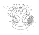
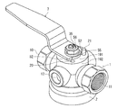
- FIG. 1 is a perspective view showing a first embodiment of a rapid exhaust valve for a railway vehicle according to the present invention.
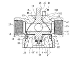
- FIG. 2 is an enlarged longitudinal sectional view of FIG. 1.
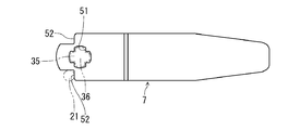
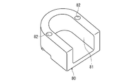
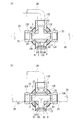
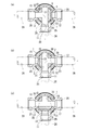
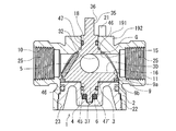
- (A) (b) (c) is sectional drawing which shows the rotation state of the valve body in 1st Embodiment. It is a top view which shows the handle for manual operation. It is the perspective view which showed the nozzle.
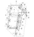
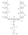
- It is a schematic diagram showing an embodiment of a railway vehicle piping system.
- FIG. 19 is a sectional view taken along line BB in FIG. It is the perspective view which attached the handle for manual operation to the rapid exhaust valve for rail vehicles of 3rd Embodiment shown in FIG.
- FIG. 19 is a cross-sectional view taken along line AA showing another example of the quick exhaust valve shown in FIG. 18 and showing an exhaust state of the exhaust valve.
- FIG. 1 is a perspective view of a first embodiment of a railway vehicle rapid exhaust valve according to the present invention
- FIG. 2 is a longitudinally enlarged sectional view of the rapid exhaust valve of FIG.
- the rapid exhaust valve for railcars (hereinafter referred to as a valve body 1) of the present invention includes a body 2, a valve body 3, a lid member 4, a seal member 5, a spring member 6 comprising a disc spring, a manual operation handle 7, and an exhaust.
- the orifice 8 is provided.
- the body 2 of the valve body 1 is formed in a one-piece structure with a material such as bronze, brass, stainless steel, and the like, and has an outflow inlet 10, 11 and an exhaust port 12 intersecting with the outflow inlet 10, 11.
- exhaust ports 12 are formed at intervals of 90 ° between the two outflow ports 10 and 11 connected in series.
- the valve body 1 can be piped in such a state that the direction of the two outlets 10 and 11 can be changed and the direction of the exhaust port 12 can be reversed by 180 ° due to the overall shape of the body 2.
- a valve body storage portion 16 having a spherical surface portion 15 is formed on a part of the inner periphery of the body 2, and a shaft mounting portion 17 is provided on the upper side of the valve body storage portion 16.
- the insertion hole 18 is provided in the.
- a flange portion 19 is formed in the upper portion of the shaft mounting portion 17, and mounting holes 20 are formed at four positions at 90 ° intervals in the flange portion 19, and a locking pin is provided in any one of the mounting holes 20. 21 is attached, for example, by press fitting or screwing.
- An opening 22 is formed on the lower side of the valve body storage portion 16 so that an internal thread 23 is provided in the opening 22.
- the spherical portion 15 is provided in a substantially hemispherical concave shape by a substantially hemispherical counterbore process.
- the exhaust port 12 has substantially the same diameter as the outflow ports 10 and 11 and is formed in communication with the valve body storage portion 16 together with the outflow ports 10 and 11.
- the exhaust port 12 is formed to penetrate, for example, with a diameter of ⁇ 12 mm, and a counterbore portion 24 of ⁇ 15 mm, for example, is formed around the exhaust port 12 by machining.
- a screwing portion 25 that is a female screw portion is formed on the inner peripheral side of the outflow inlets 10 and 11, and a pipe 26 can be connected to the outflow inlets 10 and 11 via the screwing portion 25.
- the valve body 3 is inserted into the valve body storage portion 16 through the opening 22 of the body 2 and is rotatably mounted in a state of being positioned in the vertical direction.
- the valve body 3 is provided with a spherical surface portion 28 in part, and in this embodiment, the outer peripheral surface of the valve body 3 is formed of a hemispherical spherical surface portion 28.
- a plurality of through holes 30, 31, 32 that can communicate with the outflow inlets 10, 11 or the exhaust port 12 are formed in three directions on the outer peripheral surface of the spherical surface portion 28.
- a mounting groove 33 that can be opposed to the outflow inlets 10 and 11 or the exhaust port 12 is formed in the lateral direction intersecting with 32.
- the mounting groove 33 is detachably mounted with an elastic seal member 5 capable of closing the outflow inlets 10 and 11 or the exhaust port 12.
- the mounting groove 33 is a circular concave groove, and the seal member 5 is formed in a disk shape that can be fitted into the circular concave groove 33.
- the through holes 30, 31, and 32 are formed in a full bore shape having substantially the same diameter as the outflow inlets 10, 11, or the exhaust port 12, and pressure loss when communicating with the outflow ports 10, 11, or the exhaust port 12 is suppressed. It has been.
- the through-holes 30, 31, and 32 have a narrowed diameter called a standard bore type (reduced diameter) having a flow path diameter of one stage (reduced diameter) or a reduced bore type having two stages. It can also be a type. Since the full bore type can suppress pressure loss more than other types, the flow characteristics are improved.
- an upper stem 35 to which the handle 7 can be attached is provided integrally or separately on the upper part of the valve body 3, and a fitting projection 36 is formed at the handle mounting position of the upper stem 35.
- a lower stem 37 is integrally provided on the side facing the upper stem 35.
- the upper stem 35 and the lower stem 37 are provided with substantially the same shaft diameter, and the valve body 3 is provided with an equal pressure by the air pressure in the pipe. It comes to grant.
- the valve body 3 has a shape that can be inserted into the spherical portion 15, and in this case, the through holes 30, 31, 32 and the seal member 5 rotate so as to face the outflow inlets 10, 11 or the exhaust port 12.
- the portion corresponding to the spherical surface portion 28 may have a shape other than the hemispherical surface.
- a gap G is provided between the spherical surface portion 28 and the spherical surface portion 15, and the amount of the gap G is adjusted by the rotation of the lid member 4, thereby restricting the amount of additional tightening when the valve body 3 is further tightened. it can.
- the seal member 5 attached to the valve body 3 is made of a polymer material such as PTFE (polytetrafluoroethylene) or PTFE containing carbon fiber.
- the seal member 5 rotates integrally with the valve body 3 when the valve body 3 is rotated, and can seal the outflow inlets 10 and 11 or the exhaust port 12, respectively, while the outflow inlets 10 and 11 or A fluid can be flowed when it deviates from the exhaust port 12.
- the lid member 4 is provided in a shape that allows the opening 22 to be covered, and a cylindrical portion 40 is formed on the outer periphery of the upper portion.
- the cylindrical portion 40 is provided with an outer diameter that can be fitted into the opening 22 of the body 2, and an O-ring 42 is attached to the outer periphery thereof.
- a male screw 43 that can be screwed into the female screw 23 of the body 2 is provided on the outer periphery of the lower portion of the cylindrical portion 40.
- the valve element 3 can be tightened by the male screw 43 and the female screw 23 via a spring member 6 described later.
- the opening 22 can be covered.
- An insertion hole 45 is provided at the central position of the lid member 4 on the valve body 3 side, and the gap between the insertion hole 45 and the columnar part 40 is thinned to reduce the weight of the entire lid member 4. Is planned.
- the height of the lid member 4 in FIG. 2 is kept low, whereby the overall height of the valve body 1 is also suppressed.
- the upper stem 35 is mounted in the insertion hole 18 of the body 2 via the seal material 47 made of an O-ring, and the lower stem 37 is installed in the insertion hole portion 45 of the lid member 4. It is a trunnion structure that is pivotally supported between the body 2 and the lid member 4 by being mounted via the '.
- a gap dimension 46 is provided between the upper stem 35 and the body 2.
- the valve body 3 is provided so as to be openable and closable via a handle 7 attached to the upper portion of the upper stem 35.
- a spring member 6 whose upper and lower surfaces are disc springs is mounted, and the sealing member 5 is moved by the elastic force of the spring member 6. Pressing, any one of the outflow ports 10 and 11 or the exhaust port 12 is hermetically closed, and the outflow ports 10 and 11 and the exhaust port 12, or the outflow ports 10 and 11 pass through the through ports 30, 31, and 32. So that they can communicate with each other.
- the exhaust orifice 8 is provided with an outer diameter that can be accommodated in the counterbore 24 of the exhaust port 12, and, for example, the hole diameter ⁇ d in FIG. , ⁇ 6 mm, ⁇ 8 mm, and ⁇ 10 mm, a communication hole 60 is drilled.
- the orifice 8 is covered with an annular cover 61 while being accommodated in the counterbore 24, and the cover 61 is screwed to the body 2 with screws 62 and fixed.
- the valve body 1 When the orifice diameters are set as described above, the valve body 1 can be set in a state where the valve body 1 is piped to the railway vehicle 70 shown in FIG. 10, and an appropriate exhaust port diameter can be selected with the same valve by attaching or removing the orifice 8. It becomes possible to do.
- the orifice 8 serves as a mechanism capable of appropriately adjusting the exhaust port area S shown by the two-dot chain line in FIG. 2 by selecting the exhaust port diameter. By adjusting the exhaust port area S, the railway vehicle can be used in emergency or security.
- the exhaust time for exhausting from the pressure pipe (air pipe) 71 can be set constant.
- the exhaust port area S ( ⁇ ⁇ ⁇ d 2 ) / 4 ( ⁇ d: hole diameter), and the hole diameter of the orifice 8 is ⁇ 6 mm, ⁇ 8 mm, ⁇ 10 mm, or the hole diameter of the exhaust port 12 is ⁇ 12 mm.
- the exhaust port area S is approximately 28.27 mm 2 , 50.27 mm 2 , 78.54 mm 2 , and 113.10 mm 2 , respectively.
- the lid member 4 is screwed into the opening 22 by an external thread 43 and an internal thread 23 via an O-ring 42, and is provided so as to be able to advance and retreat in the body 2.
- the pressing force of the seal member 5 due to can be adjusted.
- the spring member 6 is compressed and the valve body 3 is pushed in the insertion direction by the spring force of the spring member 6, and the adhesion force between the seal member 5 and the spherical surface portion 15 is increased.
- the primary back pressure (biflow) sealability is secured.
- the valve body 3 is mounted at a predetermined position of the valve body housing portion 16 while absorbing the dimensional error of the body 2 and the valve body 3 by the spring member 6.
- the spring member 6 may be in a mode other than the disc spring as long as it has an elastic force.
- the handle 7 shown in FIG. 4 is provided with a substantially cross-shaped fitting hole 51 that can be fitted to the fitting protrusion 36, and the handle 7 is inserted into the upper stem 35 through the fitting hole 51 at 90 ° intervals. It can be installed in any orientation. In this case, as long as the handle 7 can be attached to the upper stem 35 at 90 ° intervals, the fitting hole 51 and the fitting protrusion 36 may have a fitting shape other than a substantially cross shape.
- the handle 7 is formed with a notch-shaped stopper portion 52, and this stopper portion 52 abuts and locks on the locking pin 21 mounted in any one of the four mounting holes 20, thereby the handle 7.
- the flow path can be switched by rotating the handle 7 by 90 ° in an arbitrary operation direction.
- An exhaust groove 81 that allows the exhaust port 12 to communicate with the outside is formed inside the nozzle 80, and two through holes 82 for attaching screws 62 are formed at two locations on the outer periphery of the nozzle.
- the screw 62 can be fixed to the exhaust port 12.
- the nozzle 80 is fixed by screwing the nozzle 80 with the through hole 82 aligned with the female screw while the exhaust groove 81 is in a desired direction.
- the direction of the pressure air from the mouth 12 can be changed.
- the direction of the exhaust port 12 can be set more finely.
- FIG. 6 shows a state in which an elbow pipe 83 is connected to the exhaust port 12 of the valve body 1.
- a female screw portion 84 is formed on the end side of the exhaust port 12, and a male screw portion 85 formed on the elbow pipe 83 can be screwed to the female screw portion 84.
- the exhaust direction of the elbow pipe 83 may be freely changed while changing the screwing amount.
- the exhaust direction may be set while accommodating the orifice 8 having the communication hole 60 with an appropriate hole diameter ⁇ d in the counterbore portion 24 as in the case where the nozzle 80 is provided.
- the exhaust port area S can be adjusted by connecting an air joint to the exhaust port 12.
- a dustproof cap 90 may be provided, and the dustproof cap 90 may prevent foreign matter from entering the inside of the valve body 1 from the exhaust port 12.
- the dustproof cap 90 is provided with an annular connecting portion 91 that can be connected to the body 2, and the connecting portion 91 prevents the cap body 92 connected to the connecting portion 91 from falling off from the body 2.
- the cap body 92 when the pressure air is exhausted from the exhaust port 12, the cap body 92 is connected to the body 2 by the air pressure discharged from the exhaust port 12 while maintaining the connected state to the body 2 by the connecting portion 91.
- the exhaust port 12 is opened by being detached from the exhaust port 12.
- the exhaust port 12 can be returned to the closed state by attaching the cap body 92 to the exhaust port 12 as shown in FIG. It becomes.
- FIG. 7 shows a state in which the silencer 100 is attached to the valve body 1.
- the silencer 100 is formed with a male screw portion 101 that is screwed into the female screw portion 84, and is mounted on the exhaust port 12 side by screwing of the male screw portion 101.
- the silencer 100 may be any commercially available air, and its internal structure is not limited. When the silencer 100 is mounted, the exhaust sound from the valve body 1 when the pressure air is exhausted is reduced.
- FIG. 8 shows a state in which the check valve 110 is mounted on the valve body 1.
- the check valve 110 has a structure called a lift check valve, and includes a body portion 111, a check valve body 112, and a spring 113.
- the body part 111 has a substantially cylindrical shape, a communication hole 114 communicating with the exhaust port 12, a valve seat part 115 on which the check valve body 112 is seated, an annular locking part 116 for locking one end side of the spring 113,
- the external thread 117 is screwed into the female thread portion 85.
- the check valve body 110 is mounted in a state of being pressed to the valve seat 115 side by a spring 113 locked to the locking portion 116.
- the sealing member 5 seals the exhaust port 12, so that the primary side of the check valve 110 is in a non-pressure state, and the check valve body 112 is connected to the spring 113. It will be in the state seated on the valve seat part 115 by the elastic force. In this state, when the valve body 3 is rotated so that the seal member 5 is on the primary side of the piping to be in an exhaust state, the residual air pressure on the secondary side pushes the check valve body 112 against the elastic force of the spring 113. Opening it will exhaust the pressure air to the outside. Since the check valve 110 that opens in the exhaust direction is attached to the exhaust port 12 in this way, foreign matter and water can be prevented from entering the exhaust port 12 from the outside.
- the orifice 8 is accommodated in the counterbore 24 of the body 2, and the cover 61 is fixed with screws 62 from above to attach the orifice 8 to the body 2.
- the sealing member 5 and the sealing materials 47, 47 ′ are mounted on the valve body 3, and the valve body 3 is inserted into the valve body housing portion 16 of the spherical surface portion 15 from the lower portion of the body 2 through the opening 22, The stem 35 is inserted into the insertion hole 18. At this time, the seal member 5 is in contact with the body 2 in a state where no pressing force is applied.
- the spring member 6 made of a disc spring is attached to the insertion hole portion 45 of the lid member 4, and the lid member 4 is attached by screwing the male screw 45 and the female screw 23 while inserting the lower stem 37 into the insertion hole portion 45.
- the valve body 3 is pressed from the lower part of the body 2 through the thrust washer 9 ′ by the lid member 4.
- the lid member 4 is tightened and disassembled with a general-purpose tool such as a socket wrench (not shown), and the lid member 4 is adjusted while adjusting the amount of tightening of the lid member 4 so that the pressing force of the seal member 5 by the spring member 6 is in an appropriate state.
- valve body 3 has a so-called bottom entry structure in which the valve body 3 is inserted from below the body 2, the position of the valve body 3 with respect to the body 2 is adjusted by the lid member 4, and the body 2 and the valve body 3.
- the valve body 3 can be easily mounted at a predetermined position of the valve body storage portion 16 while absorbing the dimensional error.
- the valve body 1 may be provided in a top entry structure in which the valve body 3 is inserted from above the body 2.
- the locking pin 21 is attached to any one of the attachment holes 20, the fitting hole 51 is fitted to the fitting projection 36 of the upper stem 35, and fixed with the fixing nut 56 via the washer member 55.
- the handle 7 is attached to the upper stem 35 while arbitrarily setting the direction and the opening / closing operation direction.
- the direction of the two outlets 10 and 11 connected in series can be changed to reverse the direction of the exhaust port 12 by 180 °, and the handle 7 can be opened via the fitting hole 51 and the fitting projection 36. It is possible to change the orientation in the state to a direction parallel to or intersecting with the outflow inlets 10, 11, and an operation for opening and closing the handle 7 by attaching a locking pin 21 to any mounting hole 20 of the body 2. Since the direction can be changed, various modes of valves can be configured by combining these three elements.
- the handle 7 After assembly of the valve body 1, the handle 7 is rotated while providing a gap G between the valve body storage portion 16 and the spherical surface portion 28, and the valve body 3 is rotated every 90 ° while preventing accidents due to erroneous operation. It becomes possible. Thereby, any one or all of the outflow ports 10, 11, and 12 are communicated with each other via the through-holes 30, 31, 32 and the seal member 5, and the flow path can be switched.
- the seal member 5 At the closed position of the valve body 3, the seal member 5 is in a state where any of the outflow inlets 10, 11, and 12 is hermetically sealed.
- FIG. 3A shows a state in which the right and left outlets 10 and 11 are connected to enable supply of pressurized air, and the exhaust port 12 is directly sealed by the seal member 5.
- FIG. 3B shows a state in which the primary side outflow inlet 10 is sealed by the seal member 5 and the secondary side outflow inlet 11 and the exhaust port 12 communicate with each other. The pressure air is discharged from 11 through the exhaust port 12.
- FIG. 3C shows a state in which the primary outlet / inlet 11 is sealed by the seal member 5 so that the secondary outlet 10 and the exhaust 12 communicate with each other. Pressure air is discharged through the mouth 12.
- three or more outlets are provided in the body of the valve body, one exhaust port is provided between the outlets, and at least one of the outlets is connected to the exhaust port. It may be. Further, as a mechanism for adjusting the exhaust port area S, a communication hole having a desired exhaust port area S may be directly formed in the exhaust port of the body without attaching an orifice.
- the inlets 10 and 11 and the exhaust port 12 are formed in the valve body storage portion 16 having the spherical surface portion 15 with substantially the same diameter, and the through ports 30 and 31 are formed from the opening portion 22.
- the valve body 3 having the spherical surface portion 28 having the seal member 5 is rotatably inserted to form the body 2 in a one-piece structure, and the outflow ports 10 and 11, the exhaust port 12, and the through ports 30, 31, and 32 are formed.
- any one of the outlets 10 and 11 or the exhaust port 12 is hermetically closed with the seal member 5, and the outlets 10 and 11 and the exhaust port 12 or the outlets 10 and 11 are sealed.
- the valve body 1 has a trunnion structure in which the upper stem 35 is mounted on the insertion hole 18 of the body 2, and the lower stem 37 is mounted on the insertion hole 45 of the lid member 4. Is not moved to the secondary side due to pressure, and the seal member 5 for closing the outflow inlets 10 and 11 or the exhaust port 12 is disposed on the valve body 3 side, so that it is like a general ball valve.
- the flow path can be switched by one seal member 5 without requiring a plurality of seal members.
- the spherical surface portion 15 of the body 2, the spherical surface portion 28 of the valve body 3, and the seal member 5 can be reduced in size and weight by reducing the number of parts and reducing the number of parts without requiring high processing accuracy. If the processing accuracy of the spherical surface portion 15 of the valve body storage portion 16, more specifically, the opening portion (the valve seat surface of the body) of the outflow inlets 10 and 11 is ensured, the valve body 3 is inserted into the body 2, and the lid member By covering with 4, it can be easily assembled into a predetermined state while ensuring sealing performance. At the time of this assembly, a variety of flow paths can be switched by providing the seal member 5 at a predetermined position. Further, since the single seal member 5 is provided, a sealed space like a floating ball is not formed, and abnormal pressure increase does not occur.
- the sealing member 5 When the valve is closed, the sealing member 5 is pressed against the opening part of the inlet / outlet 10 or 11 or the outlet 12 and the sealing surface is elastically or plastically deformed. To prevent. For example, even when the seal member 5 is about to expand due to the supply of high-temperature air, the seal sealing force is applied by the pressurizing structure by the spring member 6 to prevent leakage due to biting, creep, stress relaxation, etc. Even when the seal member 5 is about to contract, the spring member 6 can provide the necessary sealing pressing force of the fluid, so that the sealing performance can be ensured. From the above, high sealing performance is exhibited against high-pressure air while maintaining compactness.
- FIG. 9 the other example of the rapid exhaust valve for rail vehicles of this invention is shown.
- the same part as the said embodiment is represented with the same code
- the valve main body 130 in this embodiment three outflow inlets 132, 133, 134 are formed in the body 131 at intervals of 90 °, and one exhaust port 135 is provided between the outflow inlets 132, 133, 134.
- the valve body 3 is rotated from the pressure air supply state, at least one of the outflow inlets 132, 133, and 134 and the exhaust port 135 can be communicated with each other.
- valve main body 130 If a two-way valve is used in the branch flow path, this two-way valve, a T-joint for branching, and a joint such as a nipple joint for connecting them are required. These are not necessary by using the valve main body 130, and it is advantageous in terms of piping work, cost, weight reduction, etc. by using it for the air piping 71 provided in the extremely small space in the railway vehicle 70. . Furthermore, a valve body (not shown) may be provided with four or more outflow inlets and one exhaust port, and a valve body having an appropriate through hole may be provided in the body.
- the nozzle 80 or the elbow pipe 83 is connected to the exhaust port 135 of the valve main body 130 so that the exhaust direction can be changed to four directions or any direction of 360 °, the installation location of the valve main body 130 can be changed.
- the exhaust direction can be set without difficulty.
- the opening time is typically 2 to 4 seconds
- the closing time is typically 3 to 5 seconds.
- These times are determined by supplying the air pressure value for opening or closing the door drive cylinder piston provided in the automatic door opening and closing device, the cylinder volume of the door drive cylinder, and the pressure chamber to the cylinder chamber.
- it is greatly influenced by the size of the aforementioned exhaust port area for exhausting the residual pressure air in the cylinder chamber in the closed or open direction.
- the time until each door is manually opened is the standard time described above. However, when all the doors are manually opened all at once, depending on the residual pressure air capacity and residual air pressure value. As a time until manual operation becomes possible, a time longer than the standard time is required.
- the doors are opened in different areas such as emergency doors from the outside of the railway vehicle (simultaneous opening of the left and right side doors, simultaneous opening of the left and right side doors).
- the exhaust hole is small and the size of the exhaust hole cannot be adjusted, so the exhaust required for opening the door for each exhaust pattern with different exhaust capacity Time has led to change.
- the door can be opened with a short exhaust time of several seconds.
- the piping capacity increases and the exhaust time is, for example, several times. It takes a long time of 10 seconds, and it takes time before the door can be opened.
- the exhaust time varies depending on the piping capacity of each pattern of door opening and closing, and the time until operation is possible varies greatly. It took a lot of waiting time.
- the conventional two-way / three-way cock valves with exhaust holes and the two-way / three-way ball cock valves are difficult to solve such problems.
- the size of the vehicle increases, making piping in a narrow space of the vehicle difficult and increasing the weight of the valve, making it difficult to meet the need for lighter vehicles. Further, a large torque is required for opening and closing the valve, and the steering wheel operation becomes difficult for passengers with weak power such as elderly people.
- the ball cock valve has a structure in which the body body is divided and fixed with screws, so the pressure air due to valve breakage when the pipes are screwed in, loose joint threads, or loose joint threads due to vehicle vibration. The risk of external leaks increases.
- the system main body 140 using the railway vehicle rapid exhaust valve of the present invention, as shown in FIGS. Arranged in the middle of the main pipe 141 and branch pipe 142 of the air pipe 71 for driving the automatic door opening and closing device 120 of the railway vehicle 70 shown by a two-dot chain line, or provided in a plural number in the pipe branching section 143
- the valve main body 1 is kept constant by preventing fluctuations in the exhaust time.
- the exhaust time can be adjusted by appropriately setting the exhaust port area S by the orifice 8 while reducing the size and weight of the entire air pipe 71 according to the position of the valve body 1 on the railcar 70. Even when the pipe capacity changes depending on each pattern at the time of opening and closing the door, the exhaust can be performed within a certain short predetermined time. In this case, since the valve body 1 can be operated with a light force and can be connected to the air pipe 71 via the body 2 having an integral structure, external leakage of pressurized air is also prevented.
- valve body 1 is provided in the middle of the pressure pipe 71 for opening the door inside the vehicle of the railway vehicle 70 or outside the vehicle, the automatic door 121 is opened manually from the inside and outside of the rail vehicle 70. Therefore, a desired area of the air pipe 71 can be quickly exhausted in an emergency or safety.
- the system main body 140 in this embodiment is provided with a compression device 150 consisting of a compressor, an air reservoir 151 consisting of a chamber and an accumulator on the primary side, and supply of pressurized air for driving the automatic door opening and closing device 120 to these.
- An air pipe 71 that is an exhaust path is connected.
- an automatic door opening / closing device 120 having a cylinder driven by opening / closing of an electromagnetic valve (not shown) and the valve body 1 are disposed.
- the pressure air generated by the compression device 150 is supplied to the air pipe 71 via the air reservoir 151.
- the air pipe 71 indicated by a solid line is branched into left and right first branch paths 153 and second branch paths 154 that are branch pipes 142 by T-shaped joints that become pipe branch sections 143 in the middle.
- a plurality of automatic door opening and closing devices 120 are provided on the first and second branch paths 153 and 154, respectively.
- the above-described bilateral valve body 1 is disposed in the middle of the main pipe 141 and branch pipe 142 of the air pipe 71.
- the valve body 130 may be provided at the pipe branching portion.
- valve body 1 provided on the primary side of the T-shaped joint 143 communicates the outlets 10 and 11 and the exhaust port 12 of the pipe line via the through ports 30, 31 and 32, and performs all automatic operations.
- Pressure air to the door opening / closing device 120 can be discharged, or the inlet / outlet ports 10, 11 can be connected to each other via the through-holes 30, 31, 32 to supply pressure air to all automatic door opening / closing devices 120.
- the inlets 10 and 11 and the exhaust port 12 are communicated to discharge pressure air to all the automatic door opening and closing devices 120 on the left and right sides, or the outlets 10 and 11 are communicated with each other on the left and right sides.
- each automatic door opening / closing device 120 communicates the inlet / outlet ports 10, 11 to the automatic door opening / closing device 120 with the exhaust port 12 to supply the pressure air to the automatic door opening / closing device 120.
- the automatic door opening and closing device 120 can be supplied with pressurized air by discharging or communicating with the outflow ports 10 and 11.
- valve body 1 is provided inside the railway vehicle 70 and outside the railway vehicle 70, respectively, and pressure air from the inside and outside of the railway vehicle 70 to the automatic door opening / closing device 120 is discharged by opening and closing each valve body 1. Or supply is possible. More specifically, the valve body 1 on the primary side of the first branch path 153 and the second branch path 154 is not shown, but is normally a glass plate that can be opened and closed with a hinge at an appropriate position inside the railway vehicle 70. It is provided in a state hidden in the door, and can be manually operated from the inside of the railway vehicle 70 by the handle 7 by opening the glass plate in an emergency or security.
- the valve body 1 provided in a state exposed to the left and right sides outside the railway vehicle 70 and the front and rear sides is provided so as to be manually operable from each direction outside the railway vehicle 70.
- the valve body 1 provided above each automatic door 121 is provided in a state concealed by a steel plate that can be opened and closed with a hinge, and is provided so that it can be manually operated from within the railway vehicle 70 by opening the steel plate. .
- the outlets 10 and 11 of all the valve bodies 1 are in communication with each other so that pressurized air can be supplied to the automatic door opening and closing device 120.
- the cylinder is driven by opening / closing the electromagnetic valve, and the automatic door opening / closing device 120 is automatically opened / closed, so that it is possible to get on / off the railway vehicle 70 and the like.
- FIG. 11 shows an exhaust state when only the individual automatic door opening / closing device 120 can be manually opened in an emergency.
- the alternate long and short dash line indicates the supply state of the pressurized air to the air pipe 71
- the broken line indicates the exhaust state of the pressurized air from the air pipe 71.
- FIG. 12 shows an exhaust state in a case where one side doors of the railway vehicle 70 can be manually opened simultaneously in an emergency. In this case, it is possible to manually open any one of the one-side doors by manually operating the valve body 1 on the outer surface of the railway vehicle 70 to bring the secondary side air piping into an exhausted state.
- FIG. 13 shows an exhaust state in a case where one side doors of the railway vehicle 70 can be manually opened simultaneously in an emergency as in the case of FIG. In this case, by manually operating the valve body 1 on the front and rear surface portions of the railway vehicle 70 to put the secondary side air piping into an exhausted state, any one of the one side doors can be manually opened.
- FIG. 14 shows an exhaust state when the automatic door opening / closing device 120 of the entire railway vehicle 70 can be manually opened in an emergency.
- the valve body 1 in the railway vehicle 70 by manually operating the valve body 1 in the railway vehicle 70 to bring the secondary side air piping 71 into an exhausted state, any of the automatic doors of the entire railway vehicle 70 is manually opened. Is possible.
- the exhaust port 12 of each valve body 1 of the railway vehicle 70 is fitted with the orifice 8 having a different exhaust port area S, and the exhaust time can be set constant in any exhaust state, and this exhaust time can be shortened.
- the hole diameter ⁇ d of the orifice 8 can be set in the piping state of the valve main body 1 without being affected by the capacity (length) of the door opening / closing air piping 71 and the arrangement position of the valve main body 1 depending on the railway vehicle 70.
- the time from the outside to the manual door opening operation is adjusted, and in this embodiment, the pressure in the air pipe 71 can be discharged within 5 seconds, for example, to enable the door opening operation.
- valve body 1 can be disposed in the middle of the main pipe 141 and branch pipe 142 of the air pipe 71 of the automatic door opening and closing device 120 in the railway vehicle 70 or in the pipe branching portion 143, Different air pipes 71 can be arranged at desired positions, and can be quickly exhausted from the desired position by switching the flow path to exhaust within a predetermined area in the railway vehicle 70 within a predetermined time. Furthermore, even when the piping is complicated, the valve main body 1 is provided at a predetermined position of the piping, and the exhaust time of the pressurized air can be shortened within a predetermined range.
- FIG. 15 shows another example of a railway vehicle piping system.
- the compressor 150 and the air reservoir 151 are provided on the primary side as described above, and an air pipe 71 for driving the automatic door opening and closing device 120 is connected to the air compressor 71.
- the two-sided valve body 1 shown in FIG. 3 for installation is disposed for installation inside the vehicle and for installation outside the vehicle.
- the three-sided valve main body 130 shown in FIG. The valve body 130 is provided at a pipe branching portion 143 between the first branching path 153 and the second branching path 154 with the outflow inlet 132 as the primary side and the outflow inlets 133 and 134 as the secondary side.
- the outflow inlet 132 and the outflow inlets 133 and 134 are communicated with each other so that the pressurized air can be supplied to all the automatic door opening and closing devices 120.
- FIG. 9B when the outflow ports 133 and 134 and the exhaust port 135 are communicated with each other, the doors on both sides of the railway vehicle 70 can be manually operated all at once. .
- the three-sided valve main body 130 is provided as the pipe branching portion 143 in place of the T-shaped joint, a valve on the primary side of the valve main body 130 becomes unnecessary, and space can be saved.
- the orifice diameter of the valve main body 1 provided on the primary side from the pipe branching portion 143 is ⁇ 10 mm, and is provided in each pipe line extending from the pipe branching portion 143 to the left and right doors.
- the exhaust time was obtained by simulation.
- the pipe diameter of the air pipe 71 is 3 / 8B
- the diameter of the exhaust port 135 is 10 mm
- the diameter of the orifice 8 is 10 mm
- 7 mm the diameter of the orifice 8
- 5 mm the pressure air pressure is 0.49 MPa.
- the exhaust time until the manual opening operation of the automatic door opening and closing device 120 was simulated with a calculation formula according to JISB 8373 in each exhaust pattern. Table 1 shows the exhaust pattern of the air pipe 71 and its simulation result.
- the exhaust time could be shortened within about 5 seconds.
- the exhaust time is as long as about 20 seconds at the maximum, and the exhaust time varies depending on the exhaust pattern. From the above, it was confirmed that when the piping system using the quick exhaust valve of the present invention is used, the exhaust time can be set short within a certain time.
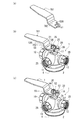
- FIG. 16 (a) is a perspective view of the handle 701
- FIGS. 16 (b) and 16 (c) are perspective views of the second embodiment of the rapid exhaust valve for a railway vehicle of the present invention
- FIG. (B) It is sectional drawing which shows the rotation state of the valve body of the rapid exhaust valve for rail vehicles shown to (c).
- the same part as 1st Embodiment is represented by the same code
- FIG. 16A is a perspective view of another type of handle 701 provided in the valve body 1
- FIG. 16B is a perspective view in which the handle 701 is provided in the valve body 1 of this example.
- the handle 701 is provided with a substantially cross-shaped fitting hole 51 in the connecting portion 702 like the handle 7, and the handle 701 is inserted into the upper stem 35 through the fitting hole 51. It is provided so that it can be mounted in any orientation at intervals. As long as the handle 701 can be attached to the upper stem 35 at 90 ° intervals, the fitting hole 51 may have a fitting shape other than a substantially cross shape.
- the connecting portion 702 is fixed to the upper stem 35 with a fixing nut 56 via a washer member 55.
- the stopper portion 520 of the handle 701 is formed by cutting out into a concave shape. As shown in FIG. 4B, when the handle 701 is attached to the valve body 1, the stopper portion 520 contacts the locking pin 21 attached to any one of the four attachment holes 20. By locking, the flow path can be switched by rotating the handle 701 180 degrees in an arbitrary operation direction while setting the direction and the operation direction of the handle 701.
- the outflow inlet 10 is the primary side and the outflow inlet 11 is the secondary side.
- the handle 701 is opened / closed by 180 ° to connect the outflow inlets 10 and 11 to supply pressurized air during operation, or the outflow inlet 10 is closed and the outflow inlet 11 and the exhaust port 12 are connected to perform exhaust work. Can do.
- the handle 7 is opened and closed to open and close the outflow inlets 10 and 11, and the pressure during operation. Air can be supplied or the outflow inlet 11 can be closed and the outflow inlet 10 and the exhaust port 12 can be communicated to perform an exhaust operation.
- the handle 7 is provided on the upper stem through the fitting hole 51 so that the handle 7 can be mounted in any direction at intervals of 90 °, and the stopper portion 52 is provided in any one of the mounting holes 20 provided on the body 2 at intervals of 90 °.
- a locking pin 21 that can lock the handle 7 so that the handle 7 can be mounted in any opening / closing operation direction, a body having a different exhaust port position with respect to the outflow inlet can be provided. There is no need to change the position of the stopper part or the position of the protruding part of the body that the stopper part locks, so that one kind of body 2 and handle 7 can be used to change the piping location and direction in the railway vehicle.
- FIG. 17A shows a state in which the outlets 10 and 11 communicate with each other so that pressurized air can be supplied.
- FIG. 17B the handles 7 and 701 are moved 180 degrees from FIG. 17A.
- FIG. 17 (c) shows a state in which the inflow / outlet opening 10 is closed by closing the outflow / inlet 10 and the outflow / inlet 11 and the exhaust 12 are in communication with each other.
- FIG. In this state the outflow inlet 11 is closed and the left outflow inlet 10 and the exhaust port 12 are communicated.
- the body 2 is provided in a one-piece structure, and the outflow inlets 10 and 11, the exhaust port 12 and the through holes 30, 31, and 32 are communicated with each other through a full bore diameter to secure the maximum flow path area.
- a large flow rate can be supplied.
- the supply amount of pressurized air during operation increases, and FIG. 17B and FIG. ).
- the secondary residual air pressure can be exhausted through the through holes 30, 31, 32 in a short time during vehicle repair / maintenance / emergency.
- a seal member is disposed on the outflow inlet side, a ball valve body is disposed at a position where a contact surface pressure necessary for sealing is applied to the seal member, and the ball valve body is rotated. It is structured to close the fluid by moving.
- a seal member in order to close each outflow inlet, it is necessary to arrange a seal member at a position where the diameter of the ball valve body spherical surface is larger than the flow path diameter of the outflow inlet. It is necessary to interfere and press the seal member.
- valve structure becomes complicated and large with an increase in the number of outflow inlets, leading to an increase in weight, and high dimensional accuracy of each component is also required.
- the seal member is disposed at a position where it interferes with the ball valve body and needs to be in pressure contact with each other, so that the structure inside the ball valve becomes complicated.
- a separate insert from the body is provided, and the insert is screwed from the piping connection of the body to protect the seal member and the seal member and the ball valve body along the flow path direction. It becomes a structure to tighten together.
- a cap is provided separately from the body, and the cap is screwed in from the flow path side of the body to hold the seal member, and the ball valve body and the seal member are moved along the flow path direction. It becomes a structure to tighten.
- the trunnion ball valve has a structure in which each seal member is tightened so as to come into contact with the ball valve body along the flow path direction from the pipe connection portion of the body.
- the upper stem 35 is inserted into the insertion hole 18 of the body 2 and the lower stem 37 is inserted into the lid member 4.
- the flow path can be switched by one seal member 5 without requiring a plurality of seal members unlike a general ball valve.
- the spherical surface portion 15 of the body 2, the spherical surface portion 28 of the valve body 3, and the seal member 5 can be reduced in size and weight by reducing the number of parts and reducing the number of parts without requiring high processing accuracy. If the processing accuracy of the spherical surface portion 15 of the valve body storage portion 16, more specifically, the opening portion (the valve seat surface of the body) of the outflow inlets 10 and 11 is ensured, the valve body 3 is inserted into the body 2, and the lid member By covering with 4, it can be easily assembled into a predetermined state while ensuring sealing performance. At the time of this assembly, by providing the seal member 5 at a predetermined position, various flow paths can be switched while preventing abnormal pressure increase.
- the pipe 26 shown in FIG. 17 is a bent pipe such as an elbow.
- valve body 3 Since the valve body 3 is pivotally supported between the body 2 and the lid member 4 and the torque performance is improved, the load at the time of operating the handle 7 is lightened, and the opening / closing operation of the valve body 3 becomes smooth. . At this time, by providing the upper stem 35 and the lower stem 37 with substantially the same diameter and applying an equal pressure, the valve body 3 can be opened and closed with a stable operability while keeping the operating torque low. Thus, even when installed in a narrow space in the railway vehicle, it can be easily operated with one hand without applying a large force.
- the valve body 3 to which the seal member 5 is mounted in advance is inserted from the opening 22 of the body 2 provided in a one-piece structure, and can be easily assembled by simply screwing the lid member while mounting the spring member.
- the one-piece structure can prevent external leakage from the body 2 after piping.
- the valve element 3 is pressed into the body by the spring member 6 by the bottom entry structure, the valve element 3 is safe without being projected to the outside. For these reasons, connection to the piping of the railway vehicle and maintenance are easy, and leakage and the like can be prevented and these operations can be performed safely.
- the gap member G is provided between the inner spherical surface portion 15 and the spherical surface portion 28 when the lid member 4 is screwed into the opening 22 and the male screw 43 is screwed into the female screw 23, and the valve body
- the spherical surface portion 3 and the inner spherical surface portion 15 can be rotated without sliding, and fluid pressure is applied to the seal member 5 only when it is closed, so that the seal member can be used without using a lubricant such as grease. 5 is minimized, and deformation and movement due to fluid pressure are also prevented, so that the high sealing performance and durability of the seal member 5 can be maintained.
- the wear of the seal member 5 is suppressed, it is excellent in economic efficiency, and the cost can be reduced when a large number of pipes are installed on one pipe in the railway vehicle.
- the opening 22 is covered with the lid member 4 so as to be tightened, and the sealing member 5 seals and closes any one of the outflow inlets 10, 11, 12 by the elastic force of the spring member 6 attached to the lid member 4. Therefore, the sealing performance can be ensured by following the spring member 6 so as to extend an appropriate amount according to the wear of the sheet member 5. Furthermore, when the sealing member 5 is worn due to deterioration over time or repeated opening and closing operations of the valve body 3 and it becomes difficult to maintain the sealing performance, the lid member 4 is tightened to increase the pressing force of the sealing member 5. The sealability can be recovered. For this reason, it is not necessary to frequently replace the seal member 5. It is difficult to apply a pressure deviated from the fluid pressure to the seal member 5, and the deformation of the seal member 5 can be prevented and the durability can be improved.
- the handle 7, 701 is spaced 90 ° through the fitting hole 51 to the upper stem.
- the locking pin 21 that can lock the stopper portions 52 and 520 is attached to any one or two of the mounting holes 20 provided in the body 2 at intervals of 90 °.
- 7, 701 can be mounted in any opening / closing operation direction, so that it can be mounted according to the piping location and orientation in the railway vehicle using one type of body 2, handle 7, 701, It can be installed side by side while ensuring operability in narrow installation spaces on the left and right sides of railway vehicles.
- the stopper portions 52 and 520 are locked to the locking pins 21 at intervals of 90 °, so that they can be reliably operated up to a predetermined angle while preventing malfunctions. Even when the valve body 1 is installed in a dark place or the like, the valve body can be easily operated to a predetermined open / close state by rotating the handle to the restriction position.
- FIG. 18 shows a perspective view of an example of a third embodiment of the rapid exhaust valve for a railway vehicle of the present invention
- FIG. 19 shows a longitudinal sectional view taken along the line AA of FIG.
- FIG. 20 is a longitudinal sectional view of the 45 ° oblique BB section line of FIG. 18,
- FIG. 21 is a perspective view in which this manual handle is attached to the third embodiment of the railway vehicle rapid exhaust valve of the present invention.
- FIG. 22 shows another example of the third embodiment of the quick exhaust valve shown in FIG. 18, and is a longitudinal sectional view taken along the line AA showing the exhaust state of the exhaust valve of this other example.
- the same part as 1st Embodiment or 2nd Embodiment is represented by the same code
- a planar portion 191 that forms a substantially circular outer edge portion is formed on the upper portion of the body 2, and the planar portion 191 is interposed via a substantially cylindrical side surface 192.
- the body 2 is integrated with the body 2.
- a mounting hole 18 for mounting the upper stem 35 of the valve body 3 is opened at the center of the flat surface portion 191, and mounting holes 20 are formed at four positions at intervals of 90 °.
- One of the locking pins 21 is attached by, for example, press-fitting or screwing.
- the outflow inlet 10 is the secondary side
- the outflow inlet 11 is the primary side.
- a mounting inner peripheral surface 9 a is formed on the lower inner peripheral surface of the valve body storage portion 16 of the body 2, and a mounting step 9 b is formed on the lower outer peripheral surface of the valve body 3.
- a holding ring 9 made of a material such as phosphor bronze or POM (polyoxymethylene) resin is fitted into the step 9b.
- the present invention is not limited to the use as a rapid exhaust valve for a railway vehicle in such a technical field.
- two-way, three-way, four-way, or It can also be used as a multi-way rotary valve. That is, the present invention is used as a flow rate adjusting rotary valve used for switching a flow path in a heat medium (cold / hot water) control piping system of a heat exchanger, and as a flow rate adjusting or opening / closing in a bypass piping such as steam.
- Rotary valves various multi-way valves used for branching in piping systems for high-pressure water, oil, gas, air, etc., various sanitary types that are easy to disassemble and assemble, easy to sterilize and flush, and have high maintainability It can also be used as a multi-way valve, a manual or automatic multi-way valve used for opening / closing, draining, testing, flow path switching, etc. in a fire prevention sprinkler facility disaster prevention valve unit.
Landscapes
- Engineering & Computer Science (AREA)
- General Engineering & Computer Science (AREA)
- Mechanical Engineering (AREA)
- Taps Or Cocks (AREA)
- Multiple-Way Valves (AREA)
- Sliding Valves (AREA)
- Details Of Valves (AREA)
- Self-Closing Valves And Venting Or Aerating Valves (AREA)
Abstract
Priority Applications (4)
| Application Number | Priority Date | Filing Date | Title |
|---|---|---|---|
| DE112014003555.6T DE112014003555T5 (de) | 2013-08-02 | 2014-08-04 | Schnellauslassventil für Schienenfahrzeuge sowie Verrohrungssystem eines Schienenfahrzeugs |
| US14/909,308 US20160178074A1 (en) | 2013-08-02 | 2014-08-04 | Rapid exhaust valve for railway vehicles and piping system of railway vehicle |
| JP2014553559A JP5775978B2 (ja) | 2013-08-02 | 2014-08-04 | 鉄道車両用急速排気弁と鉄道車両の配管システム |
| CN201480054667.8A CN105659011B (zh) | 2013-08-02 | 2014-08-04 | 铁路车辆用急速排气阀和铁路车辆的配管系统 |
Applications Claiming Priority (4)
| Application Number | Priority Date | Filing Date | Title |
|---|---|---|---|
| JP2013161658 | 2013-08-02 | ||
| JP2013-161658 | 2013-08-02 | ||
| JP2014026365 | 2014-02-14 | ||
| JP2014-026365 | 2014-02-14 |
Publications (1)
| Publication Number | Publication Date |
|---|---|
| WO2015016380A1 true WO2015016380A1 (fr) | 2015-02-05 |
Family
ID=52431899
Family Applications (1)
| Application Number | Title | Priority Date | Filing Date |
|---|---|---|---|
| PCT/JP2014/070515 Ceased WO2015016380A1 (fr) | 2013-08-02 | 2014-08-04 | Soupape d'échappement rapide pour véhicule ferroviaire ainsi que système de tuyauterie pour véhicule ferroviaire |
Country Status (5)
| Country | Link |
|---|---|
| US (1) | US20160178074A1 (fr) |
| JP (1) | JP5775978B2 (fr) |
| CN (1) | CN105659011B (fr) |
| DE (1) | DE112014003555T5 (fr) |
| WO (1) | WO2015016380A1 (fr) |
Cited By (3)
| Publication number | Priority date | Publication date | Assignee | Title |
|---|---|---|---|---|
| CN115506879A (zh) * | 2022-07-29 | 2022-12-23 | 重庆长安汽车股份有限公司 | 车辆的热管理系统及车辆 |
| WO2023106005A1 (fr) * | 2021-12-10 | 2023-06-15 | 株式会社不二工機 | Soupape de commutation de circuit d'écoulement |
| WO2023171034A1 (fr) * | 2022-03-09 | 2023-09-14 | 株式会社不二工機 | Soupape de commutation de trajet d'écoulement |
Families Citing this family (20)
| Publication number | Priority date | Publication date | Assignee | Title |
|---|---|---|---|---|
| US20170321814A1 (en) * | 2014-12-11 | 2017-11-09 | Kitz Corporation | Rotary valve and quick exhaust valve for railway vehicle |
| GB2546322A (en) * | 2016-01-15 | 2017-07-19 | Singh Bath Charanjit | A device for flushing a system |
| DE102016113467B4 (de) * | 2016-07-21 | 2023-01-26 | Heraeus Medical Gmbh | Knochenzement-Applikator mit Dreiwege-Ventil zur Druckentlastung und Verfahren zum Auspressen eines Knochenzements mit dem Knochenzement-Applikator |
| DE102016113468A1 (de) | 2016-07-21 | 2018-01-25 | Heraeus Medical Gmbh | Knochenzement-Applikator mit Dreiwege-Ventil zur Druckentlastung |
| US10295076B2 (en) * | 2016-11-02 | 2019-05-21 | Schaeffler Technologies AG & Co. KG | Modular electro-mechanical rotary valve with activated seal interface |
| CN110067877B (zh) * | 2018-01-24 | 2020-06-09 | 中车唐山机车车辆有限公司 | 一种可单独控制的双向供风截断塞门 |
| DE102018216217A1 (de) * | 2018-09-24 | 2020-03-26 | Lufthansa Technik Ag | Entlüftungsventil |
| CN108980408A (zh) * | 2018-09-28 | 2018-12-11 | 张伟 | 一种液体流向自动换向阀 |
| KR102586451B1 (ko) * | 2018-10-18 | 2023-10-06 | 현대자동차주식회사 | 머플러용 가변 밸브 및 이를 포함하는 듀얼 머플러 |
| US11473966B2 (en) * | 2018-12-19 | 2022-10-18 | A&D Company, Limited | Electronic balance |
| JP2020204369A (ja) * | 2019-06-18 | 2020-12-24 | Ckd株式会社 | ダイアフラムバルブの製造方法 |
| JP7238762B2 (ja) * | 2019-12-25 | 2023-03-14 | 新東工業株式会社 | 自動ガス抜き弁 |
| CN113442961B (zh) * | 2020-03-25 | 2023-04-18 | 中车唐山机车车辆有限公司 | 一种车辆门立罩挡缝板模块及列车 |
| CN112780948A (zh) * | 2020-12-25 | 2021-05-11 | 福建福清核电有限公司 | 一种核电厂sebim先导式安全阀充水排气装置及方法 |
| CN113147832B (zh) * | 2021-04-25 | 2023-06-20 | 郑州铁路职业技术学院 | 一种铁路调度控制中心人机交互用报警装置 |
| CN113983200A (zh) * | 2021-10-29 | 2022-01-28 | 火树科技有限公司 | 一种方便快速切换的三通阀 |
| CN114517888B (zh) * | 2022-03-09 | 2024-06-21 | 浙江工业大学 | 一种基于自增强理论的站用储氢气瓶的自增强工艺 |
| CN114834422B (zh) * | 2022-05-13 | 2024-07-19 | 中车南京浦镇车辆有限公司 | 一种能实现板式安装的双侧排风缓解阀 |
| CN115523309A (zh) * | 2022-10-25 | 2022-12-27 | 程超 | 一种自过滤易净型的新式阀门 |
| KR200499970Y1 (ko) * | 2025-03-25 | 2026-01-21 | 엔케이에너지 주식회사 | 압축가스용 레귤레이터 |
Citations (4)
| Publication number | Priority date | Publication date | Assignee | Title |
|---|---|---|---|---|
| JPH0236664U (fr) * | 1988-09-01 | 1990-03-09 | ||
| JPH0979391A (ja) * | 1995-09-14 | 1997-03-25 | Fanenshumitto Arnold | ボールバルブ |
| JPH10273040A (ja) * | 1997-03-31 | 1998-10-13 | Nabco Ltd | 鉄道車両用ボールコック |
| JP2012002355A (ja) * | 2010-05-20 | 2012-01-05 | Kitz Corp | 回転弁 |
Family Cites Families (29)
| Publication number | Priority date | Publication date | Assignee | Title |
|---|---|---|---|---|
| US2698731A (en) * | 1949-06-29 | 1955-01-04 | Gustave J Koehler | Fluid valve |
| US3485265A (en) * | 1965-12-01 | 1969-12-23 | Becton Dickinson Co | Three-way stopcock |
| US3552439A (en) * | 1967-11-07 | 1971-01-05 | Chester A Siver | Plug valve with resilient seal |
| US4232709A (en) * | 1978-10-20 | 1980-11-11 | Westinghouse Air Brake Company | Four-way ball valve |
| WO1984001799A1 (fr) * | 1982-11-05 | 1984-05-10 | Hydril Co | Procede et appareil a vanne de securite |
| US4681133A (en) * | 1982-11-05 | 1987-07-21 | Hydril Company | Rotatable ball valve apparatus and method |
| US5115837A (en) * | 1991-09-25 | 1992-05-26 | Tupper Willis E | Ball fuel valve with reserve position |
| US5439052A (en) * | 1994-01-29 | 1995-08-08 | Skinner; Earl F. | Pitless adapter valve for wells |
| US5482249A (en) * | 1994-06-21 | 1996-01-09 | Fisher Controls International, Inc. | Fluid control valve with attenuator and dynamic seal |
| US5927330A (en) * | 1996-02-06 | 1999-07-27 | Oil States Industries | Modular, high-volume, rotary selector valve |
| US5944055A (en) * | 1997-09-05 | 1999-08-31 | Dicky; Julius | Control valve with swivel connector |
| AU1597200A (en) * | 1998-10-16 | 2000-05-08 | 02 Technologies, Inc. | Bottled water cooler with built-in oxygen generator and oxygen injection system |
| US6675834B1 (en) * | 2002-02-11 | 2004-01-13 | Hung-Lin Lai | Structure for switching flow of fluid in a fluid-conveying system |
| US7089960B2 (en) * | 2003-06-13 | 2006-08-15 | Tlv Co. Ltd. | Ball valve |
| WO2005031200A1 (fr) * | 2003-09-23 | 2005-04-07 | Webstone Company, Inc. | Soupape de sectionnement munie d'une soupape en drain |
| US7789106B2 (en) * | 2003-09-23 | 2010-09-07 | Webstone Company, Inc. | Hot water fluid isolation valve |
| US20050121087A1 (en) * | 2003-12-09 | 2005-06-09 | Tien-Shou Tsai | Three-way valve |
| CA2480501C (fr) * | 2004-09-28 | 2011-03-29 | Argus Machine Co. Ltd. | Clapet a bille de raclage |
| US20060065313A1 (en) * | 2004-09-30 | 2006-03-30 | Sebastiano Saleri | Regulator and mixer ball valve |
| US7255131B2 (en) * | 2005-09-22 | 2007-08-14 | Paper John C | Valve for a fire hose line |
| US7409966B2 (en) * | 2006-05-04 | 2008-08-12 | Hung-Chung Chang | Ball valve |
| US20080169443A1 (en) * | 2007-01-17 | 2008-07-17 | Donald Loloff | Ball valve |
| US8375991B2 (en) * | 2009-01-26 | 2013-02-19 | Watts Regulator Company | Valve assembly |
| US8413684B2 (en) * | 2009-09-16 | 2013-04-09 | Schneider Electric Buildings, Llc | Ball valve with anti-rotational pressure plate |
| US8375977B2 (en) * | 2010-04-22 | 2013-02-19 | A.S. Jones & Company Inc. | Ball valve with single access port |
| CN202768948U (zh) * | 2012-08-31 | 2013-03-06 | 南车株洲电力机车有限公司 | 一种轨道车辆手动解钩阀 |
| DE102012109756B4 (de) * | 2012-10-12 | 2015-01-08 | Sed Flow Control Gmbh | Steigendes Handventil mit Hubbegrenzung |
| US8881767B2 (en) * | 2013-02-25 | 2014-11-11 | Conbraco Industries, Inc. | Ball valve and seat assembly with life-sustaining flow |
| DE102013206097A1 (de) * | 2013-04-05 | 2014-10-09 | Airbus Operations Gmbh | Absperrventil |
-
2014
- 2014-08-04 US US14/909,308 patent/US20160178074A1/en not_active Abandoned
- 2014-08-04 WO PCT/JP2014/070515 patent/WO2015016380A1/fr not_active Ceased
- 2014-08-04 JP JP2014553559A patent/JP5775978B2/ja active Active
- 2014-08-04 DE DE112014003555.6T patent/DE112014003555T5/de not_active Withdrawn
- 2014-08-04 CN CN201480054667.8A patent/CN105659011B/zh not_active Expired - Fee Related
Patent Citations (4)
| Publication number | Priority date | Publication date | Assignee | Title |
|---|---|---|---|---|
| JPH0236664U (fr) * | 1988-09-01 | 1990-03-09 | ||
| JPH0979391A (ja) * | 1995-09-14 | 1997-03-25 | Fanenshumitto Arnold | ボールバルブ |
| JPH10273040A (ja) * | 1997-03-31 | 1998-10-13 | Nabco Ltd | 鉄道車両用ボールコック |
| JP2012002355A (ja) * | 2010-05-20 | 2012-01-05 | Kitz Corp | 回転弁 |
Cited By (5)
| Publication number | Priority date | Publication date | Assignee | Title |
|---|---|---|---|---|
| WO2023106005A1 (fr) * | 2021-12-10 | 2023-06-15 | 株式会社不二工機 | Soupape de commutation de circuit d'écoulement |
| WO2023171034A1 (fr) * | 2022-03-09 | 2023-09-14 | 株式会社不二工機 | Soupape de commutation de trajet d'écoulement |
| JP7549369B2 (ja) | 2022-03-09 | 2024-09-11 | 株式会社不二工機 | 流路切換弁 |
| CN115506879A (zh) * | 2022-07-29 | 2022-12-23 | 重庆长安汽车股份有限公司 | 车辆的热管理系统及车辆 |
| CN115506879B (zh) * | 2022-07-29 | 2024-04-09 | 重庆长安汽车股份有限公司 | 车辆的热管理系统及车辆 |
Also Published As
| Publication number | Publication date |
|---|---|
| CN105659011A (zh) | 2016-06-08 |
| DE112014003555T5 (de) | 2016-04-28 |
| US20160178074A1 (en) | 2016-06-23 |
| JP5775978B2 (ja) | 2015-09-09 |
| JPWO2015016380A1 (ja) | 2017-03-02 |
| CN105659011B (zh) | 2017-12-08 |
Similar Documents
| Publication | Publication Date | Title |
|---|---|---|
| JP5775978B2 (ja) | 鉄道車両用急速排気弁と鉄道車両の配管システム | |
| JP6649272B2 (ja) | 回転弁と鉄道車両用急速排気弁 | |
| EP2438331B1 (fr) | Vanne d'arrêt vérifiable hemiwedge | |
| JP2017025958A (ja) | 回転弁とこれを用いた鉄道車両用急速排気弁 | |
| US10228064B2 (en) | Multi-ported refrigeration valve assembly | |
| WO2009020286A1 (fr) | Robinet à tournant sphérique doté d'une unité de prévention de retour de fluide | |
| JP2017025957A (ja) | 回転弁とこれを用いた鉄道車両用急速排気弁 | |
| EP4031788A1 (fr) | Ensemble clapet à bille | |
| US20110266480A1 (en) | Ball valve isolator | |
| JP6242046B2 (ja) | アクチュエータ付き回転弁 | |
| KR20050087770A (ko) | 가스공급용 안전밸브 | |
| JP2007139010A (ja) | ボールバルブ | |
| NO315758B1 (no) | Armatur, s¶rlig regulerings- og stengeklaff | |
| RU159493U1 (ru) | Запорно-регулирующий шаровой кран | |
| KR20170099511A (ko) | 역류방지 체크밸브 | |
| WO2016099337A1 (fr) | Robinet à tournant sphérique de fermeture et régulation | |
| RU2267683C1 (ru) | Шаровой кран двухстороннего действия для высоких давлений | |
| US6016826A (en) | Automatic center cavity equalizing valve | |
| JPH11148565A (ja) | ボールバルブ | |
| KR101098244B1 (ko) | 굴삭기 어태치먼트용 스톱밸브 | |
| RU2357141C1 (ru) | Кран двухконтурный | |
| RU2243438C2 (ru) | Шаровой кран двухстороннего действия для высоких давлений | |
| US20060207662A1 (en) | Pressure relief valve | |
| US20050230653A1 (en) | Low pressure stem gas seal | |
| WO2026092427A1 (fr) | Clapet à bille comprenant un dispositif de relâchement de pression unidirectionnel |
Legal Events
| Date | Code | Title | Description |
|---|---|---|---|
| ENP | Entry into the national phase |
Ref document number: 2014553559 Country of ref document: JP Kind code of ref document: A |
|
| 121 | Ep: the epo has been informed by wipo that ep was designated in this application |
Ref document number: 14831984 Country of ref document: EP Kind code of ref document: A1 |
|
| WWE | Wipo information: entry into national phase |
Ref document number: 14909308 Country of ref document: US |
|
| WWE | Wipo information: entry into national phase |
Ref document number: 112014003555 Country of ref document: DE |
|
| 122 | Ep: pct application non-entry in european phase |
Ref document number: 14831984 Country of ref document: EP Kind code of ref document: A1 |