WO2015050102A1 - Endoscope - Google Patents
Endoscope Download PDFInfo
- Publication number
- WO2015050102A1 WO2015050102A1 PCT/JP2014/076022 JP2014076022W WO2015050102A1 WO 2015050102 A1 WO2015050102 A1 WO 2015050102A1 JP 2014076022 W JP2014076022 W JP 2014076022W WO 2015050102 A1 WO2015050102 A1 WO 2015050102A1
- Authority
- WO
- WIPO (PCT)
- Prior art keywords
- insertion portion
- tube
- hand
- endoscope
- inner tube
- Prior art date
- Legal status (The legal status is an assumption and is not a legal conclusion. Google has not performed a legal analysis and makes no representation as to the accuracy of the status listed.)
- Ceased
Links
Images


Classifications
-
- A—HUMAN NECESSITIES
- A61—MEDICAL OR VETERINARY SCIENCE; HYGIENE
- A61B—DIAGNOSIS; SURGERY; IDENTIFICATION
- A61B1/00—Instruments for performing medical examinations of the interior of cavities or tubes of the body by visual or photographical inspection, e.g. endoscopes; Illuminating arrangements therefor
- A61B1/00112—Connection or coupling means
- A61B1/00121—Connectors, fasteners and adapters, e.g. on the endoscope handle
- A61B1/00126—Connectors, fasteners and adapters, e.g. on the endoscope handle optical, e.g. for light supply cables
-
- A—HUMAN NECESSITIES
- A61—MEDICAL OR VETERINARY SCIENCE; HYGIENE
- A61B—DIAGNOSIS; SURGERY; IDENTIFICATION
- A61B1/00—Instruments for performing medical examinations of the interior of cavities or tubes of the body by visual or photographical inspection, e.g. endoscopes; Illuminating arrangements therefor
- A61B1/00064—Constructional details of the endoscope body
- A61B1/00066—Proximal part of endoscope body, e.g. handles
-
- A—HUMAN NECESSITIES
- A61—MEDICAL OR VETERINARY SCIENCE; HYGIENE
- A61B—DIAGNOSIS; SURGERY; IDENTIFICATION
- A61B1/00—Instruments for performing medical examinations of the interior of cavities or tubes of the body by visual or photographical inspection, e.g. endoscopes; Illuminating arrangements therefor
- A61B1/00064—Constructional details of the endoscope body
- A61B1/00105—Constructional details of the endoscope body characterised by modular construction
-
- G—PHYSICS
- G02—OPTICS
- G02B—OPTICAL ELEMENTS, SYSTEMS OR APPARATUS
- G02B23/00—Telescopes, e.g. binoculars; Periscopes; Instruments for viewing the inside of hollow bodies; Viewfinders; Optical aiming or sighting devices
- G02B23/24—Instruments or systems for viewing the inside of hollow bodies, e.g. fibrescopes
- G02B23/2476—Non-optical details, e.g. housings, mountings, supports
-
- A—HUMAN NECESSITIES
- A61—MEDICAL OR VETERINARY SCIENCE; HYGIENE
- A61B—DIAGNOSIS; SURGERY; IDENTIFICATION
- A61B1/00—Instruments for performing medical examinations of the interior of cavities or tubes of the body by visual or photographical inspection, e.g. endoscopes; Illuminating arrangements therefor
- A61B1/04—Instruments for performing medical examinations of the interior of cavities or tubes of the body by visual or photographical inspection, e.g. endoscopes; Illuminating arrangements therefor combined with photographic or television appliances
-
- A—HUMAN NECESSITIES
- A61—MEDICAL OR VETERINARY SCIENCE; HYGIENE
- A61B—DIAGNOSIS; SURGERY; IDENTIFICATION
- A61B1/00—Instruments for performing medical examinations of the interior of cavities or tubes of the body by visual or photographical inspection, e.g. endoscopes; Illuminating arrangements therefor
- A61B1/06—Instruments for performing medical examinations of the interior of cavities or tubes of the body by visual or photographical inspection, e.g. endoscopes; Illuminating arrangements therefor with illuminating arrangements
Definitions
- the present invention relates to an endoscope, and more particularly to an endoscope structure suitable for a disposable specification.
- this type of endoscope has an insertion portion extending from a hand portion.
- An illumination optical system such as an optical fiber that transmits illumination light from a light source, and an optical system such as a relay lens that transmits image light and an optical fiber are provided inside the insertion portion (see Patent Documents 1 and 2).
- the distal end portion including the insertion portion is separable from the hand portion including the imaging portion.
- the present invention provides an endoscope including a hand portion and an insertion portion extending from the hand portion along an axis, wherein the hand portion and the insertion portion are separate members.
- a cylindrical connecting member that is configured and separable, and has elasticity, and the connecting member covers the distal end portion of the proximal portion and the proximal end portion of the insertion portion, and the proximal portion
- the insertion portion and the insertion portion are elastically in close contact with a peripheral surface of one member and are integrally joined with the other member of the insertion portion and the insertion portion, thereby connecting the proximal portion and the insertion portion to each other It is characterized by being separably connected by a member.
- the insertion portion can be made disposable or replaced by separating the hand portion and the insertion portion.
- the connecting member itself can function as a sealing member, a sealing member such as an O-ring is unnecessary, not only can the number of parts be reduced, but there is no need to form a housing portion for the sealing member,
- the configuration can be simplified. This makes it possible to provide an endoscope that is inexpensive and suitable for disposable specifications.
- an objective element is provided at the distal end portion of the insertion portion, and an imaging element is provided at the proximal portion.
- the endoscope includes an adjustment unit that variably adjusts a relative position of the one member and the connection member along the axis line of the hand portion and the insertion portion. Accordingly, for example, when a new insertion portion is connected to the proximal portion, the distance between the objective element and the imaging element can be finely adjusted according to the focal length.
- the adjusting means includes a pinion provided on the connection member and a rack provided on the one member of the hand portion and the insertion portion and meshing with the pinion, and the meshing is released by elastic deformation of the connection member.
- the adjustment means can have a simple configuration. Since the connecting member also has a function of releasing the above engagement, it is not necessary to provide a separate engagement release mechanism.
- the hand portion includes an outer casing and a holding portion that is housed in the outer casing so as to be movable along the axis, and the imaging element is held in the holding portion, and the insertion portion
- the position of the housing and the outer casing is fixed via the connection member, and the relative position of the insertion portion and the holding portion is adjusted by the adjusting means along the axis. Accordingly, the position of the holding portion (and hence the imaging element) and the objective element can be adjusted in the direction along the axis (axial direction) while keeping the outer casing and the connecting member from shifting from each other. The sealing performance between the two can be ensured.
- the insertion portion is provided with an outer tube extending along an axis and an inner tube accommodated in the outer tube, and illumination light from a light source is transmitted between the outer tube and the inner tube.
- An illumination light transmission medium made of any one of gas, liquid, and translucent resin is accommodated. Inside the inner tube, any of gas, liquid, or translucent resin that transmits image light to be observed is contained.
- An image light transmission medium comprising: Is preferred.
- the light source is provided at the proximal portion, and a conical recess having a conical shape whose diameter is reduced toward the insertion portion is formed inside the connection member, and the inner tube passes through the conical recess,
- a conical annular light guide made of glass, translucent resin, or gas that guides the illumination light between the outer tube and the inner tube between the inner surface of the conical recess and the outer surface of the inner tube It is preferable that a portion is provided. When separating the hand portion and the insertion portion, the illumination means can be easily separated between the light source and the light guide portion.
- an endoscope suitable for making the insertion portion disposable can be provided with a simple and inexpensive configuration that allows the hand portion and the insertion portion to be detachable while ensuring sealing performance. it can.
- FIG.1 (a) is a longitudinal cross-sectional view which shows the rigid endoscope which concerns on 1st Embodiment of this invention in the state in which the insertion part and the hand part were connected.
- FIG. 1B is a longitudinal sectional view showing the rigid endoscope in a state where the insertion portion and the hand portion are separated.
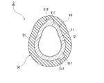
- FIG. 2 is a cross-sectional view taken along the line II-II in FIG. 1A, omitting the internal structure of the rigid endoscope.
- It is a longitudinal cross-sectional view which expands and shows a part of said rigid endoscope.
- It is a perspective view of the light guide member of the said rigid endoscope.
- It is a block diagram of the endoscope apparatus containing the said rigid endoscope.
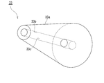
- FIG.6 (a) is a side view which shows the rigid endoscope which concerns on 2nd Embodiment of this invention in the state in which the insertion part and the hand part were connected.
- FIG. 6B is a side view showing the rigid endoscope according to the second embodiment with the insertion portion and the hand portion separated.
- the endoscope apparatus 1 includes a rigid endoscope 2, a camera control unit (CCU) 3, and a monitor 4.
- the rigid endoscope 2 is, for example, an ophthalmic endoscope, but the present invention is not limited to this.
- the rigid endoscope 2 includes a hand portion 10, an insertion portion 20, an illumination unit 30, and an observation unit 40.
- the insertion portion 20 is connected to the distal end of the hand portion 10 (left side in FIG. 1A).
- Illumination means 30 and observation means 40 are provided inside the hand portion 10 and the insertion portion 20.
- the hand portion 10 is held by an operator, and the insertion portion 20 is inserted into an observation target such as an eye socket or lacrimal gland of a human body.
- the observation object around the distal end of the insertion portion 20 is illuminated by the illumination means 30.
- the image light to be observed is taken into the endoscope 2 by the observation means 40 and displayed on the monitor 4 through image processing by the CCU 3.
- the hand portion 10 and the insertion portion 20 are constituted by separate members and are separable (detachable).
- the hand portion 10 includes an outer casing 11, an inner casing 12, a sleeve 13, and a shaft tube 14, and has a multiple cylindrical shape extending along the axis L.
- the cross-sectional shape of the hand portion 10 is a deformed ellipse shape similar to an oval shape.
- an inner casing 12 is accommodated in the outer casing 11, and a shaft tube 14 is accommodated in the inner casing 12 via a sleeve 13.
- the sleeve 13 and the shaft tube 14 are integrated with each other and are slidable in the axial direction (direction along the axis L) with respect to the outer casing 11 and the inner casing 12.
- the inner collar 12, the sleeve 13, and the shaft tube 14 may be integrated with each other and slidable in the axial direction with respect to the outer casing 11.
- the insertion portion 20 extends linearly along the axis L from the tip of the hand portion 10.
- the insertion portion 20 includes an outer tube 21 and an inner tube 22 and has a double circular tube shape.
- the material of the outer tube 21 is preferably a metal having elasticity, such as stainless steel, ordinary steel, iron, aluminum or the like.
- the outer tube 21 and thus the insertion portion 20 are extremely thin.
- the outer diameter of the outer tube 21 is several mm (2 mm to 3 mm) or less, preferably 1 mm or less, for example, about 0.9 mm, but the present invention is not limited to this.
- the inner tube 22 has a smaller diameter than the outer tube 21 and is accommodated in the outer tube 21 so as to be concentric with the outer tube 21.
- the material of the inner tube 22 is preferably a metal having elasticity, such as stainless steel, ordinary steel, iron, and aluminum. As shown in FIG. 1B, the base end portion (right end portion in the figure) of the inner tube 22 protrudes toward the hand portion 10 from the outer tube 21.
- a connecting pipe 23 is provided at the base end of the inner pipe 22.
- the connecting tube 23 is composed of a small-diameter tube portion 23 a on the distal end side (left in FIG. 3), a central tapered portion 23 b, and a large-diameter tube portion on the proximal end side (right in FIG. 3). 23c integrally.
- the inner tube 22 and the connecting tube 23 are integrally connected by fitting the tube portion 23 a into the outer periphery of the proximal end portion of the inner tube 22.
- a tapered portion 23b is integrally connected to the proximal end portion of the tube portion 23a.
- the diameter of the taper portion 23b is increased toward the proximal direction.
- the pipe portion 23c is integrally connected to the enlarged diameter end portion of the taper portion 23b.
- the shaft tube 14 of the hand portion 10 is fitted into the tube portion 23c so as to be slidable and detachable in the axial direction. Accordingly, the proximal end of the inner tube 22 is connected to the shaft tube 14 along the axis L via the connecting tube 23 so that the relative position can be adjusted and the separation is possible.
- a connecting member 50 is provided between the hand portion 10 and the insertion portion 20.
- the connecting member 50 is made of rubber (elastic material) and has elasticity.
- the connection member 50 integrally includes a covering cylinder portion 51 and a cap portion 52.
- the covering cylinder portion 51 is formed in a cylinder shape with the cylinder axis along the axis L, and the cross-sectional shape thereof is a deformed elliptical shape that is substantially similar to the hand portion 10.
- the base end part (the right end part in FIG.1 (b)) of the covering cylinder part 51 is opened.
- the tip end portion (left end portion in FIG. 1B) of the covering cylinder portion 51 is closed by the cap portion 52.
- the cap portion 52 has a conical wall shape that protrudes along the axis L in the tip direction (left in FIG. 1B).
- the cap 52 has a conical recess 52 a and an insertion hole 52 b formed along the axis L.
- the conical recess 52a has a conical shape with a diameter reduced toward the tip (left in FIG. 3).
- the base end on the large diameter side of the conical recess 52 a is opened to the internal space of the covering cylinder portion 51.
- An insertion hole 52b is connected to the tip on the small diameter side of the conical recess 52a.
- the insertion hole 52b has the same diameter as the tip portion of the conical recess 52a and reaches the tip surface of the connection member 50.
- connection member 50 covers the outer periphery of the proximal portion 10 and the insertion portion 20 so as to straddle between the distal end portion of the proximal portion 10 and the proximal end portion of the insertion portion 20. Yes. And the covering cylinder part 51 elastically adheres to the outer peripheral surface of the hand part 10 (one member), and the cap part 52 is joined integrally with the insertion part 20 (the other member). As a result, the hand portion 10 and the insertion portion 20 are detachably connected by the connection member 50.
- connection structure will be further described in detail.
- the base end portion of the outer tube 21 is fitted into the insertion hole 52b.
- the outer tube 21 and the cap portion 52 are integrally joined by an adhesive or the like.
- the protruding length of the outer tube 21 from the cap portion 52 is, for example, about 30 mm to 50 mm, but the present invention is not limited to this.
- the proximal end portion of the inner tube 22 protrudes from the outer tube 21 and penetrates the conical recess 52 a along the axis L, and is disposed inside the connection member 50.
- the dimension of the inner peripheral surface of the covering cylinder part 51 in a natural state (no load) is slightly smaller than the dimension of the outer peripheral surface of the front end part of the outer casing 11.
- the covering cylinder portion 51 covers the outer peripheral portion of the distal end portion of the outer casing 11, thereby being elastically adhered to the outer casing 11.
- the coated cylinder part 51 and the hand part 10 are detachably connected by this elastic force.
- a space between the inner peripheral surface of the covering cylinder portion 51 and the outer peripheral surface of the outer casing 11 is sealed in a liquid-tight manner.
- the cap portion 52 is separated from the proximal portion 10 in the distal direction (left in FIG. 1A) and covers the distal end surface of the proximal portion 10.
- a plurality (two in this case) of guide ridges 11 f are formed on the outer peripheral surface of the outer casing 11. These guide ridges 11f extend straight along the axis L and are spaced apart from each other in the circumferential direction.
- a number (here, two) of guide grooves 51f corresponding to the guide protrusions 11f are formed on the inner peripheral surface of the covering cylinder portion 51.
- the guide grooves 51f extend straight along the axis L, and are spaced apart from each other in the circumferential direction, and are disposed at positions corresponding to the guide protrusions 11f.
- Each guide ridge 11f is slidably fitted along the axis L in the corresponding guide groove 51f. As a result, the connection member 50 is prevented from rotating relative to the peripheral direction of the hand portion 10.
- a locking recess 11 e is formed in an annular shape along the circumferential direction of the outer casing 11 on the outer peripheral surface of the outer casing 11.
- a locking projection 51 e that protrudes inward in the radial direction is provided annularly along the circumferential direction of the covering cylinder 51 at the base end of the covering cylinder 51. The locking projection 51e is fitted and locked in the locking recess 11e. Thereby, the outer casing 11 and the connection member 50 are positioned in the axial direction.
- a position adjusting means 60 is provided between the connecting member 50 and the hand portion 10.
- the position adjusting means 60 includes a pinion 61 (circular gear) and a rack 62 (linear gear).
- the pinion 61 is rotatably embedded in the connection member 50.
- the connection member 50 is elastically in contact with the pinion 61, so that the space between the connection member 50 and the pinion 61 is liquid-tightly sealed.
- the rack 62 is fixed to the sleeve 13 of the hand portion 10.
- the pinion 61 and the rack 62 are engaged with each other.
- the pinion 61 By rotating the pinion 61, the axial relative positions of the connecting member 50, the sleeve 13, and the shaft tube 14 can be adjusted.
- the relative position between the connecting member 50 and the outer casing 11 is fixed. Further, the engagement between the pinion 61 and the rack 62 can be released by elastically deforming the connecting member 50.
- the observation means 40 includes an image optical system 41 and an image sensor 42.
- the image optical system 41 includes an objective lens 43 (object element), an image light transmission tube 44 (image light transmission member), and an imaging lens 45 (imaging element).
- the objective lens 43 is provided at the distal end of the inner tube 22 (that is, the distal end of the insertion portion 20).
- the image light transmission tube 44 includes the inner tube 22, the connecting tube 23, and the shaft tube 14, and extends in a straight line along the axis L. As shown in FIG. 3, the internal space of the image light transmission tube 44 is an image light transmission path 44d.
- the peripheral surface of the image light transmission path 44d (the inner surfaces of the tubes 22, 23, and 14) constitutes an image light path defining surface 44b.
- the image optical path defining surface 44b has a long cylindrical shape extending straight along the axis L so as to connect the objective lens 43 and the imaging lens 45.
- a dark color film (not shown) made of a black paint or the like is coated on the image optical path defining surface 44b. As a result, the image optical path defining surface 44b is a dark low reflection surface.
- the dark color is preferably black.
- the image optical path defining surface 44b will be referred to as a “low reflection surface 44b” as appropriate.
- the low reflection surface 44b has a cylindrical shape extending along the axis L.
- the low reflection surface 44b has a reflectance with respect to incident light from the inside smaller than the absorptance, and preferably has a sufficiently small reflectance.
- the imaging lens 45 is accommodated in the tip portion of the shaft tube 14 (holding portion) in the image light transmission tube 44. Therefore, the imaging lens 45 is provided in the hand portion 10.
- the imaging lens 45 is configured by a relay lens including a plurality of lenses in a row, and has a sufficiently large focal length corresponding to the distance between the lenses with the objective lens 43.
- a portion of the image light transmission tube 44 between the objective lens 43 and the imaging lens 45 is a cavity 44e, and no lens, optical fiber, or the like is provided between the lenses 43 and 45.
- the inner tube 22 and thus the cylindrical low reflection surface 44b communicates the objective lens 43 and the imaging lens 45, and air as an image light transmission medium is connected to the cavity 44e in the inner tube 22 (low reflection surface 44b). (Gas) is contained.
- an image sensor 42 is provided at the proximal end portion of the shaft tube 14.
- the image sensor 42 is configured by a CCD or a CMOS.
- the cable 5 is connected to the image sensor 42. As shown in FIG. 5, the cable 5 is pulled out from the proximal end portion of the hand portion 10 and connected to the CCU 3.
- the illumination unit 30 includes a plurality of light sources 31 and an illumination optical system 32.
- the light source 31 is comprised by LED (light emitting diode), Preferably it is comprised by white LED, This invention is not limited to this.
- the light source 31 is held by the sleeve 13 so as to face the distal direction (left in FIG. 1A) from the sleeve 13. Therefore, the light source 31 is arranged so as to be shifted from the axis L.
- Optical axis L 31 of the light source 31 is directed obliquely relative to the axis L.
- a plurality of light sources 31 are arranged in a ring shape in the circumferential direction of the sleeve 13 and surround the outer periphery of the distal end portion of the axial tube 14 (and thus the image light transmission tube 44).
- One annular light source may be provided so as to surround the image light transmission tube 44.
- the illumination optical system 32 includes an illumination light transmission tube 34, an exit lens 35 (illumination window), and a light guide member 33 (light guide portion).
- the illumination light transmission tube 34 is constituted by the outer tube 21 and the inner tube 22 of the insertion portion 20.
- a space 34e extending between the tubes 21 and 22 along the axis L is formed in an annular shape (cylindrical shape), and this annular cavity 34e constitutes an illumination light transmission path 34d in the insertion portion 10. ing.
- air (gas) is provided as an illumination light transmission medium.
- the outer peripheral surface (the inner surface of the outer tube 21) of the annular illumination light transmission path 34d is mirror-finished to form an outer reflecting surface 34a.
- the inner peripheral surface of the annular illumination light transmission path 34d (the outer surface of the inner tube 22) is mirror-finished to form an inner reflection surface 34b.
- the material for the mirror film include aluminum, but the present invention is not limited to this, and other glossy metals such as silver may be used.
- the inner reflection surface 34b has a cylindrical shape that extends along the axis L while surrounding the low reflection surface 44b so as to form a front and back surface with the low reflection surface 44b.
- the outer reflection surface 34a is concentric with the inner reflection surface 34b, surrounds the inner reflection surface 34b, and has a cylindrical shape extending along the axis L. Air (gas) as an illumination light transmission medium is provided between the reflecting surfaces 34a and 34b (between the outer tube 21 and the inner tube 22).
- the reflectance of the reflection surfaces 34a and 34b with respect to the illumination light is higher than the reflectance of the low reflection surface 44b with respect to the image light, and the absorption rate with respect to the illumination light of the reflection surfaces 34a and 34b is absorption with respect to the image light of the low reflection surface 44b. Lower than the rate.
- the exit lens 35 is configured by an annular concave lens.
- the exit lens 35 is fitted into the distal end portion of the illumination light transmission tube 34 (between the distal end portions of the outer tube 21 and the inner tube 22).
- the tip of the illumination light transmission path 34d is blocked by the exit lens 35.
- an annular flat glass may be provided at the tip of the illumination light transmission tube 34.
- the light guide member 33 has a conical ring shape having a center hole 33c.
- the light guide member 33 is made of transparent glass (illumination light transmission medium) and has translucency.
- the light guide member 33 may be made of a transparent optical resin (illumination light transmission medium) instead of glass.
- the light guide member 33 is accommodated in the conical recess 52a with the central axis aligned with the axis L. Accordingly, the light guide member 33 is interposed between the light source 31 and the insertion portion 20.
- the outer peripheral surface of the light guide member 33 is reduced in diameter toward the insertion portion 20 (and thus the illumination light transmission path 34d), and is in contact with the inner peripheral surface of the conical recess 52a.
- the end portion on the large diameter side of the light guide member 33 is directed to the light source 31, and the end portion on the small diameter side of the light guide member 33 is directed to the insertion portion 20.
- An annular end surface on the small diameter side of the light guide member 33 closes the base end portion of the illumination light transmission path 34d.
- a portion of the inner tube 22 and the tube portion 23a (that is, a portion of the image light transmission tube 44) is inserted through the center hole portion 33c.
- the inner peripheral surface of the center hole portion 33c is in contact with the outer peripheral surfaces of the inner tube 22 and the tube portion 23a. Therefore, the light guide member 33 surrounds the image light transmission tube 44.
- the outer peripheral surface of the light guide member 33 is mirror-finished by coating a mirror film (not shown) by vapor deposition or sputtering. As a result, the outer peripheral surface of the light guide member 33 constitutes the outer reflective surface 33a. Further, the outer peripheral surfaces of the inner tube 22 and the tube portion 23a are polished or mirror-finished by coating a mirror film (not shown) by vapor deposition or sputtering.
- the inner peripheral surface of the central hole portion 33c of the light guide member 33 is in contact with the outer peripheral surfaces of the inner tube 22 and the tube portion 23a that are mirrored, thereby forming a reflection surface 33b on the inner side of the light guide member 33. .
- An illumination light transmission medium made of glass is formed between the reflecting surfaces 33a and 33b. Examples of the material for the mirror film include aluminum, but the present invention is not limited to this, and other glossy metals such as silver may be used.
- the insertion unit 20 When observing an observation target such as an orbit of a human body with the endoscope 2, the insertion unit 20 is inserted into the observation target and illumination light is emitted from the light source 31.
- the transmission distance of the illumination light can be shortened and the transmission efficiency can be increased.
- the illumination light obliquely enters the light guide member 33 and is condensed (converged) toward the front end side of the light guide member 33 while being reflected by the reflection surfaces 33a and 33b. Illumination light can be reliably reflected by making the reflection surfaces 33a and 33b mirror surfaces, and loss of illumination light can be suppressed.
- the angle formed by the traveling direction of the illumination light and the axis L is increased.
- This illumination light is introduced into the illumination light transmission path 34 d from the tip of the light guide member 33. And it is propagated to the front end side of the illumination light transmission path 34d while being reflected by the reflecting surfaces 34a and 34b.
- Illumination light can be reliably reflected by making the reflecting surfaces 34a and 34b mirror surfaces. Even if the incident angle of the illumination light to the reflecting surfaces 34a and 34b is small, it can be reliably reflected and transmitted. Therefore, the loss of illumination light can be reduced.
- This illumination light is irradiated so as to diffuse from the exit lens 35 and illuminates the observation target.
- the angle of the optical axis L 31 of the angle and the light source 31 of the tapered outer peripheral surface of the light guide member 33 is appropriately set, can be adjusted emitting angle thus illumination range. That is, the emission angle can be increased by the light guide member 33, and the illumination range can be widened.
- the illuminated image light of the observation object enters the objective lens 43 and propagates to the proximal end side of the image light transmission path 44d.
- the image light enters the imaging lens 45 straight from the objective lens 43 and is imaged on the image sensor 42 by the imaging lens 45.
- the image sensor 42 converts this image light into an electrical signal. This signal is sent to the CCU 3 and displayed on the monitor 4 as an observation image.
- the sharpness (contrast) of the observed image can be ensured.
- the illumination light can be reliably prevented from entering the image light transmission path 44d by the inner tube 22, it is possible to more reliably prevent the observation image from becoming unclear.
- the rigid endoscope 2 since there are only two optical lenses of the image optical system 41, the objective lens 43 and the imaging lens 45, the total aberration can be sufficiently suppressed, and the aberration is corrected. This can save or simplify the trouble of reducing or reducing. Further, since the illumination light transmission medium of the illumination light transmission path 34d and the image light transmission medium of the image light transmission path 44d in the insertion section 20 are composed of air (gas), the internal structure of the insertion section 20 is simplified. it can. Therefore, the price of the rigid endoscope 2 can be reduced. In addition, the insertion portion 20 can be made extremely fine without worrying about damage to the optical element in the insertion portion 20.
- the insertion portion 20 is extremely thin, for example, having a diameter of 2 mm to 3 mm or less, preferably 1 mm or less, when the insertion portion 20 is bent by some bending load, the internal illumination light transmission medium and image light transmission medium are There is no damage. Further, since the objective lens 43 is provided at the distal end portion of the insertion portion 20, there is almost no possibility that the objective lens 43 is damaged even if the intermediate portion of the insertion portion 20 is curved. Furthermore, if the bending is within the elastic deformation region of the outer tube 21 and the inner tube 22, when the bending load is released, the insertion portion 20 naturally returns to the original straight state by the elastic restoring force of the tubes 21 and 22. Return. Therefore, it is possible to reliably irradiate the observation target with the illumination light, and to reliably collect and observe the image of the observation target.
- the used insertion portion 20 and the connection member 50 can be separated from the hand portion 10 and replaced with a new insertion portion 20 and connection member 50 each time it is used.
- the connecting member 50 is elastically deformed, the locking convex portion 51e is removed from the locking concave portion 11e, and the engagement between the pinion 61 and the rack 62 is released, and then the covering cylinder portion 51 of the connecting member 50 is removed. Pull out from the outer casing 11.
- the connection member 50 and the hand portion 10 can be easily separated, and consequently, the insertion portion 20 and the hand portion 10 can be separated.
- the engagement between the pinion 61 and the rack 62 can be released by elastic deformation of the connecting member 50, it is not necessary to provide a separate engagement release mechanism.
- the connecting member 50 is pulled out from the outer casing 11, the connecting tube 23 is pulled out from the shaft tube 14. Therefore, the observation means 40 is separated between the connecting tube 23 and the shaft tube 14. Further, the illumination means 30 can be easily separated between the light source 31 and the light guide member 33.
- the connecting tube 23 of the new insertion portion 20 is fitted into the shaft tube 14, and the covering cylinder portion 51 of the connecting member 50 integrated with the insertion portion 20 is removed. Fit into the outer periphery of the housing 11.
- the connection member 50 by inserting the guide protrusion 11f into the guide groove 51f, the connection member 50, and thus the insertion portion 20 and the proximal portion 10 can be positioned in the circumferential direction.
- the pinion 61 and the rack 62 are engaged with each other while the connecting member 50 is elastically deformed.
- the connecting member 50 and thus the insertion portion 20 and the hand portion 10 can be positioned in the axial direction.
- the position of the insertion portion 20 and the axial tube 14 is finely adjusted by turning the pinion 61 of the position adjusting means 60.
- the inter-lens distance between the objective lens 43 and the imaging lens 45 can be finely adjusted according to the focal length. It is also possible to adjust the magnification of the observation image by the position adjusting means 60.
- connection member 50 itself elastically adheres to the outer casing 11, so that the connection member 50 itself functions as a seal member. Therefore, the hand portion 10 and the insertion portion 20 can be detachably attached without complicating the seal structure. Therefore, a sealing member such as an O-ring is not necessary, and not only the number of parts can be reduced, but also a housing for the sealing member need not be formed, and the configuration can be simplified. Furthermore, the structure of the position adjusting means 60 is also simple. Therefore, even if the insertion portion 20 is disposable, it is possible to reliably avoid an increase in cost, and the endoscope 2 suitable for the disposable specification of the insertion portion 20 can be provided. Moreover, the trouble which wash
- FIG. 6A and FIG. 6B show an endoscope 2A according to the second embodiment of the present invention.
- a cylindrical connection member 55 made of elastic rubber is provided between the hand portion 10 and the insertion portion 20.
- the connecting member 55 covers the proximal portion 10 and the insertion portion 20 so as to straddle between the distal end portion of the proximal portion 10 and the proximal end portion of the insertion portion 20.
- the tapered cylindrical tip side portion 56 of the connecting member 55 is elastically adhered to the peripheral surface of the insertion portion 20 (one member), and the cylindrical proximal end side portion 57 of the connecting member 55 is at hand. It is joined integrally with the part 10 (the other member). As a result, the hand portion 10 and the insertion portion 20 are detachably connected by the connection member 55. Further, the pinion 61 of the adjusting means 60 is provided on the connection member 55, and the rack 62 is provided on the proximal end portion of the insertion portion 20.
- the illumination light transmission medium in the illumination light transmission path 34d may be made of a transparent optical resin, may be made of a liquid such as water, or may be made of an optical fiber.
- the image light transmission medium in the image light transmission path 44d may be made of a transparent optical resin, may be made of a liquid such as water, or may be made of an optical fiber or a relay lens.
- the illumination light transmission medium in the illumination light transmission path 34d is composed of a cylindrical transparent optical resin
- the image light transmission medium in the image light transmission path 44d is composed of a columnar transparent optical resin, and the above cylindrical shape
- the cylindrical transparent optical resin may be inserted into the center hole of the transparent optical resin.
- the inner tube 22 may be omitted.
- a mirror film is coated on the inner peripheral surface of the center hole of the cylindrical transparent optical resin
- a dark color film is coated on the outer peripheral surface of the cylindrical transparent optical resin.
- the outer reflective surface 33a may be configured by providing a mirror film on the inner peripheral surface of the conical recess 52a.
- the inner reflection surface 33b may be configured by providing a mirror film on the inner peripheral surface of the center hole portion 33c of the light guide member 33.
- the light guide member 33 may be omitted, the inside of the conical recess 52a may be a cavity, and the air (gas) in the conical recess 52a may be used as the illumination light transmission medium.
- the present invention is not limited to a rigid endoscope but can be applied to a flexible endoscope.
- the outer tube 21 or the inner tube 22 may be made of resin.
- Optical axis L 31 of the light source 31 may be parallel with the axis L.
- the present invention can be applied to, for example, an endoscope.
Landscapes
- Health & Medical Sciences (AREA)
- Life Sciences & Earth Sciences (AREA)
- Surgery (AREA)
- Physics & Mathematics (AREA)
- Optics & Photonics (AREA)
- Biomedical Technology (AREA)
- Animal Behavior & Ethology (AREA)
- Radiology & Medical Imaging (AREA)
- Nuclear Medicine, Radiotherapy & Molecular Imaging (AREA)
- Engineering & Computer Science (AREA)
- Biophysics (AREA)
- Heart & Thoracic Surgery (AREA)
- Medical Informatics (AREA)
- Molecular Biology (AREA)
- Pathology (AREA)
- General Health & Medical Sciences (AREA)
- Public Health (AREA)
- Veterinary Medicine (AREA)
- Astronomy & Astrophysics (AREA)
- General Physics & Mathematics (AREA)
- Endoscopes (AREA)
- Instruments For Viewing The Inside Of Hollow Bodies (AREA)
Abstract
La présente invention concerne un endoscope qui utilise une configuration simple et peu coûteuse qui permet d'accoupler une section portative et une section d'insertion et de les désaccoupler l'une de l'autre tandis que sont garanties des propriétés d'étanchéité, ce qui rend la section d'insertion appropriée à être jetée.
Un élément de raccordement élastique (50) se trouve entre la section portative (10) et la section d'insertion (20) d'un endoscope (2). L'élément de raccordement (50) enjambe et recouvre l'extrémité avant de la section portative (10) et l'extrémité de base de la section d'insertion (20), est en contact élastique rapproché avec la section portative (10), et est uni d'un seul tenant à la section d'insertion (20). Ainsi, la section portative (10) et la section d'insertion (20) sont rattachées de manière amovible l'une de l'autre.
Priority Applications (1)
| Application Number | Priority Date | Filing Date | Title |
|---|---|---|---|
| JP2015540495A JP6370301B2 (ja) | 2013-10-02 | 2014-09-30 | 内視鏡 |
Applications Claiming Priority (2)
| Application Number | Priority Date | Filing Date | Title |
|---|---|---|---|
| JP2013-207263 | 2013-10-02 | ||
| JP2013207263 | 2013-10-02 |
Publications (1)
| Publication Number | Publication Date |
|---|---|
| WO2015050102A1 true WO2015050102A1 (fr) | 2015-04-09 |
Family
ID=52778691
Family Applications (1)
| Application Number | Title | Priority Date | Filing Date |
|---|---|---|---|
| PCT/JP2014/076022 Ceased WO2015050102A1 (fr) | 2013-10-02 | 2014-09-30 | Endoscope |
Country Status (2)
| Country | Link |
|---|---|
| JP (1) | JP6370301B2 (fr) |
| WO (1) | WO2015050102A1 (fr) |
Citations (5)
| Publication number | Priority date | Publication date | Assignee | Title |
|---|---|---|---|---|
| JPH075376A (ja) * | 1993-06-17 | 1995-01-10 | Moritetsukusu:Kk | 硬性イメージスコープ |
| JPH07248454A (ja) * | 1994-03-11 | 1995-09-26 | Olympus Optical Co Ltd | 硬性内視鏡 |
| JPH08502905A (ja) * | 1992-09-01 | 1996-04-02 | エドウィン エル アデアー, | 分離可能の使い捨て管組立体を有する滅菌可能の内視鏡 |
| JPH10178A (ja) * | 1996-06-14 | 1998-01-06 | Machida Endscope Co Ltd | 内視鏡装置における照明光伝送系アダプター |
| WO1998035607A1 (fr) * | 1997-02-13 | 1998-08-20 | Matsushita Electric Industrial Co., Ltd. | Endoscope, son procede de production et element d'insertion |
Family Cites Families (2)
| Publication number | Priority date | Publication date | Assignee | Title |
|---|---|---|---|---|
| JP2587421Y2 (ja) * | 1992-04-30 | 1998-12-16 | ホーヤ株式会社 | 眼内観察用器具 |
| US8118431B2 (en) * | 2008-11-06 | 2012-02-21 | Clarity Medical Systems, Inc. | Split view adapter for a microscope |
-
2014
- 2014-09-30 WO PCT/JP2014/076022 patent/WO2015050102A1/fr not_active Ceased
- 2014-09-30 JP JP2015540495A patent/JP6370301B2/ja active Active
Patent Citations (5)
| Publication number | Priority date | Publication date | Assignee | Title |
|---|---|---|---|---|
| JPH08502905A (ja) * | 1992-09-01 | 1996-04-02 | エドウィン エル アデアー, | 分離可能の使い捨て管組立体を有する滅菌可能の内視鏡 |
| JPH075376A (ja) * | 1993-06-17 | 1995-01-10 | Moritetsukusu:Kk | 硬性イメージスコープ |
| JPH07248454A (ja) * | 1994-03-11 | 1995-09-26 | Olympus Optical Co Ltd | 硬性内視鏡 |
| JPH10178A (ja) * | 1996-06-14 | 1998-01-06 | Machida Endscope Co Ltd | 内視鏡装置における照明光伝送系アダプター |
| WO1998035607A1 (fr) * | 1997-02-13 | 1998-08-20 | Matsushita Electric Industrial Co., Ltd. | Endoscope, son procede de production et element d'insertion |
Also Published As
| Publication number | Publication date |
|---|---|
| JP6370301B2 (ja) | 2018-08-08 |
| JPWO2015050102A1 (ja) | 2017-03-09 |
Similar Documents
| Publication | Publication Date | Title |
|---|---|---|
| JPH0355943Y2 (fr) | ||
| US20110157574A1 (en) | Endoscope | |
| WO2015050100A1 (fr) | Endoscope rigide | |
| US8366611B2 (en) | Endoscope with sealing ring | |
| EP3592198B1 (fr) | Endoscope doté d'un couvercle à l'extrémité distale d'une canule | |
| JP2019500108A (ja) | 内視鏡システム | |
| JP2011237525A5 (fr) | ||
| JP6464251B2 (ja) | 照明ユニット及び内視鏡 | |
| US8531513B2 (en) | Assembly method for endoscope image pickup unit and endoscope | |
| JP5366575B2 (ja) | 複数機種の内視鏡 | |
| JP4841251B2 (ja) | 内視鏡 | |
| US20170255002A1 (en) | Image pickup optical system and image pickup unit of endoscope, and endoscope | |
| JPH10170794A (ja) | 内視鏡のレンズ装置 | |
| WO2015050101A1 (fr) | Endoscope | |
| WO2014068958A1 (fr) | Endoscope et partie d'insertion pour endoscope | |
| JP6370301B2 (ja) | 内視鏡 | |
| JP4083484B2 (ja) | 汚染防止型内視鏡の先端部 | |
| JP2009279181A (ja) | 内視鏡および内視鏡本体 | |
| JP2014191222A (ja) | 内視鏡用レンズユニットおよびこれを備えた内視鏡 | |
| CN110087527A (zh) | 内窥镜 | |
| US20200064531A1 (en) | Optical fiber connection device for connecting optical fiber and optical fiber assembly | |
| EP1662967A1 (fr) | Endoscope | |
| CN104883951A (zh) | 内窥镜装置 | |
| CN111031890B (zh) | 内窥镜用照明单元及内窥镜 | |
| JP6671967B2 (ja) | 内視鏡 |
Legal Events
| Date | Code | Title | Description |
|---|---|---|---|
| 121 | Ep: the epo has been informed by wipo that ep was designated in this application |
Ref document number: 14850945 Country of ref document: EP Kind code of ref document: A1 |
|
| ENP | Entry into the national phase |
Ref document number: 2015540495 Country of ref document: JP Kind code of ref document: A |
|
| NENP | Non-entry into the national phase |
Ref country code: DE |
|
| 122 | Ep: pct application non-entry in european phase |
Ref document number: 14850945 Country of ref document: EP Kind code of ref document: A1 |