WO2015129932A1 - ホイールローダ - Google Patents
ホイールローダ Download PDFInfo
- Publication number
- WO2015129932A1 WO2015129932A1 PCT/JP2015/059222 JP2015059222W WO2015129932A1 WO 2015129932 A1 WO2015129932 A1 WO 2015129932A1 JP 2015059222 W JP2015059222 W JP 2015059222W WO 2015129932 A1 WO2015129932 A1 WO 2015129932A1
- Authority
- WO
- WIPO (PCT)
- Prior art keywords
- boom
- bucket
- distance
- state
- wheel loader
- Prior art date
- Legal status (The legal status is an assumption and is not a legal conclusion. Google has not performed a legal analysis and makes no representation as to the accuracy of the status listed.)
- Ceased
Links
Images





Classifications
-
- E—FIXED CONSTRUCTIONS
- E02—HYDRAULIC ENGINEERING; FOUNDATIONS; SOIL SHIFTING
- E02F—DREDGING; SOIL-SHIFTING
- E02F3/00—Dredgers; Soil-shifting machines
- E02F3/04—Dredgers; Soil-shifting machines mechanically-driven
- E02F3/28—Dredgers; Soil-shifting machines mechanically-driven with digging tools mounted on a dipper- or bucket-arm, i.e. there is either one arm or a pair of arms, e.g. dippers, buckets
- E02F3/36—Component parts
- E02F3/42—Drives for dippers, buckets, dipper-arms or bucket-arms
- E02F3/43—Control of dipper or bucket position; Control of sequence of drive operations
- E02F3/431—Control of dipper or bucket position; Control of sequence of drive operations for bucket-arms, front-end loaders, dumpers or the like
- E02F3/434—Control of dipper or bucket position; Control of sequence of drive operations for bucket-arms, front-end loaders, dumpers or the like providing automatic sequences of movements, e.g. automatic dumping or loading, automatic return-to-dig
-
- E—FIXED CONSTRUCTIONS
- E02—HYDRAULIC ENGINEERING; FOUNDATIONS; SOIL SHIFTING
- E02F—DREDGING; SOIL-SHIFTING
- E02F3/00—Dredgers; Soil-shifting machines
- E02F3/04—Dredgers; Soil-shifting machines mechanically-driven
- E02F3/28—Dredgers; Soil-shifting machines mechanically-driven with digging tools mounted on a dipper- or bucket-arm, i.e. there is either one arm or a pair of arms, e.g. dippers, buckets
- E02F3/283—Dredgers; Soil-shifting machines mechanically-driven with digging tools mounted on a dipper- or bucket-arm, i.e. there is either one arm or a pair of arms, e.g. dippers, buckets with a single arm pivoted directly on the chassis
-
- E—FIXED CONSTRUCTIONS
- E02—HYDRAULIC ENGINEERING; FOUNDATIONS; SOIL SHIFTING
- E02F—DREDGING; SOIL-SHIFTING
- E02F9/00—Component parts of dredgers or soil-shifting machines, not restricted to one of the kinds covered by groups E02F3/00 - E02F7/00
- E02F9/08—Superstructures; Supports for superstructures
- E02F9/0841—Articulated frame, i.e. having at least one pivot point between two travelling gear units
-
- E—FIXED CONSTRUCTIONS
- E02—HYDRAULIC ENGINEERING; FOUNDATIONS; SOIL SHIFTING
- E02F—DREDGING; SOIL-SHIFTING
- E02F9/00—Component parts of dredgers or soil-shifting machines, not restricted to one of the kinds covered by groups E02F3/00 - E02F7/00
- E02F9/20—Drives; Control devices
- E02F9/2004—Control mechanisms, e.g. control levers
-
- E—FIXED CONSTRUCTIONS
- E02—HYDRAULIC ENGINEERING; FOUNDATIONS; SOIL SHIFTING
- E02F—DREDGING; SOIL-SHIFTING
- E02F9/00—Component parts of dredgers or soil-shifting machines, not restricted to one of the kinds covered by groups E02F3/00 - E02F7/00
- E02F9/20—Drives; Control devices
- E02F9/2025—Particular purposes of control systems not otherwise provided for
- E02F9/2029—Controlling the position of implements in function of its load, e.g. modifying the attitude of implements in accordance to vehicle speed
-
- E—FIXED CONSTRUCTIONS
- E02—HYDRAULIC ENGINEERING; FOUNDATIONS; SOIL SHIFTING
- E02F—DREDGING; SOIL-SHIFTING
- E02F9/00—Component parts of dredgers or soil-shifting machines, not restricted to one of the kinds covered by groups E02F3/00 - E02F7/00
- E02F9/20—Drives; Control devices
- E02F9/22—Hydraulic or pneumatic drives
- E02F9/2278—Hydraulic circuits
- E02F9/2296—Systems with a variable displacement pump
-
- E—FIXED CONSTRUCTIONS
- E02—HYDRAULIC ENGINEERING; FOUNDATIONS; SOIL SHIFTING
- E02F—DREDGING; SOIL-SHIFTING
- E02F9/00—Component parts of dredgers or soil-shifting machines, not restricted to one of the kinds covered by groups E02F3/00 - E02F7/00
- E02F9/26—Indicating devices
- E02F9/264—Sensors and their calibration for indicating the position of the work tool
- E02F9/265—Sensors and their calibration for indicating the position of the work tool with follow-up actions (e.g. control signals sent to actuate the work tool)
-
- E—FIXED CONSTRUCTIONS
- E02—HYDRAULIC ENGINEERING; FOUNDATIONS; SOIL SHIFTING
- E02F—DREDGING; SOIL-SHIFTING
- E02F9/00—Component parts of dredgers or soil-shifting machines, not restricted to one of the kinds covered by groups E02F3/00 - E02F7/00
- E02F9/26—Indicating devices
- E02F9/267—Diagnosing or detecting failure of vehicles
- E02F9/268—Diagnosing or detecting failure of vehicles with failure correction follow-up actions
Definitions
- a wheel loader often repeats excavation work and loading work for loading the excavated material into a vessel of a dump truck.
- an operation called V-shape operation is often repeated over a long period of time, which places a heavy burden on the operator. Therefore, in order to reduce the burden on the operator, there is a wheel loader equipped with a mode that partially automates the operation of the boom and bucket and assists loading work on the vessel or the like (see, for example, Patent Document 1). .
- the bucket loading operation is automatically started. Thereby, the operator can load with a bucket only by operating a boom lever.
- the wheel loader works by lowering the tip of the boom and placing the bucket close to the ground.
- the boom tip is raised to a position higher than the vessel of the transport work vehicle or the dump truck.
- the operator needs to perform a complicated operation such as operating the work machine with the right hand while moving the wheel loader by performing an accelerator operation (right foot), a brake operation (left foot), and a steering operation (left hand).
- an accelerator operation right foot
- a brake operation left foot
- a steering operation left hand
- One of the objects of the present invention is to provide a wheel loader that can easily carry and load excavated earth and sand.
- the wheel loader of the present invention is a wheel loader having a work machine including a boom and a bucket attached to the boom, the work state detecting means for detecting the work state of the wheel loader, and the work state detecting means.
- Target setting means for setting a relationship between a target position of the work implement and a movement distance of the wheel loader according to the work state detected in step; a movement distance detection means for detecting the movement distance of the wheel loader;
- a work implement control means for moving the boom and the bucket to a target position of the work implement determined according to the movement distance detected by the movement distance detection means.
- the target position of the work implement corresponding to the work state and the movement distance is set as the target setting means.
- the work implement control means moves the boom and bucket to this target position. For this reason, the operator only needs to perform the steering, the accelerator, and the brake operation, and it is not necessary to perform the operation of the work machine such as the boom lever and the bucket lever at the same time as the steering and the accelerator operation. Therefore, even an inexperienced operator can easily operate the wheel loader.
- the work equipment is automatically moved to an appropriate position while the wheel loader is moving, the work efficiency can be improved and fuel-saving operation can be realized as compared with the case where the work machine is moved after the wheel loader is moved. .
- the work state detection means includes a load determination means for determining whether or not a load is loaded on the bucket, and a forward / reverse determination means for determining forward and reverse of the wheel loader. And when the load determining means determines that the load is in the load state and the forward / backward determination means determines that the load is in reverse, the working state is detected as the load reverse state, and the target setting means is A relationship between a target position of the work implement and a moving distance of the wheel loader is set according to the reverse load state, and the work implement control means, when the work state is the reverse load state, It is preferable that the boom and the bucket are moved to the target position of the work implement determined according to the movement distance detected by the movement distance detection means.
- the work state detection means includes a load determination means for determining whether or not a load is loaded on the bucket, and a forward / reverse determination means for determining forward and reverse of the wheel loader. And when it is determined that the load is determined by the load determination means and the forward / backward determination means is forward, the working state is detected as a load advance state, and the target setting means is A relationship between a target position of the work implement and a moving distance of the wheel loader is set according to the load advance state, and the work implement control means, when the work state is the load advance state, It is preferable that the boom and the bucket are moved to the target position of the work implement determined according to the movement distance detected by the movement distance detection means.
- the work state detection means includes a load determination means for determining whether or not a load is loaded on the bucket, and a forward / reverse determination means for determining forward and reverse of the wheel loader. And when the load determining means determines that the load is in an empty state and the forward / backward determination means determines that the load is in reverse, the working state is detected as an unloaded reverse state, and the target setting The means sets the relationship between the target position of the work implement and the moving distance of the wheel loader according to the reverse load state, and the work implement control means is configured so that the work state is the empty reverse state. In this case, it is preferable that the boom and the bucket are moved to the target position of the working machine determined according to the movement distance detected by the movement distance detection means.
- the wheel loader of the present invention when the wheel loader moves a distance L1 from a boom angle at the start of movement in the reverse load state as the target position of the boom according to the reverse load state,
- the boom angle is set in proportion to the moving distance until the boom becomes horizontal, and the bucket is set to the tilt position in conjunction with the boom angle as the target position of the bucket according to the reverse load state. It is preferable to set the bucket cylinder length to be maintained.
- the target setting means includes a distance L2 that is a target movement distance in the forward load state, a first intermediate distance that is less than the distance L2, the first intermediate distance or more, and the distance A second intermediate distance less than L2 is set, and when the moving distance is less than the first intermediate distance, a boom angle at which the boom is horizontal is set as a target position of the boom according to the load advance state.
- the moving distance is not less than the first intermediate distance and less than the second intermediate distance Is a lifting position preset when the second intermediate distance is moved from the boom angle when the first intermediate distance is moved as a target position of the boom according to the load advance state.
- the boom angle is set in proportion to the travel distance to the boom angle that becomes the shoner position, and the bucket is maintained at the tilt position in conjunction with the boom angle as the target position of the bucket according to the load advance state.
- the boom angle of the raised positioner position is set as the boom target position according to the load advance state.
- the bucket cylinder length for maintaining the bucket in the tilt position is preferably set as the target position of the bucket according to the load advance state.
- the target setting means includes a distance L2 that is a target movement distance in the idle reverse state, a third intermediate distance that is less than the distance L2, the third intermediate distance or more, and the A fourth intermediate distance less than the distance L2 is set, and when the moving distance is less than the third intermediate distance, the boom is set in advance as a target position of the boom according to the reverse travel state.
- a boom angle as a position is set, and the wheel loader has moved the third intermediate distance from the bucket cylinder length at the start of the movement in the unloaded backward state as the target position of the bucket according to the unloaded backward state.
- the bucket cylinder length is set in proportion to the moving distance up to the bucket cylinder length at which the bucket is set to the initial position set in advance, and the moving distance is not less than the third intermediate distance.
- the boom at the time when the fourth intermediate distance is moved from the boom angle at the time when the third intermediate distance is moved as the target position of the boom according to the reverse travel state is set in proportion to the travel distance until the boom angle becomes horizontal, and the bucket is maintained at a preset initial position as a target position of the bucket in accordance with the idle load reverse state.
- the boom angle when the fourth intermediate distance is moved as the target position of the boom according to the idle reverse state Until the boom angle at which the boom at the time of the movement of the second distance L2 becomes a preset lowered positioner position, the boom angle is set in proportion to the movement distance, As the target position of the bucket in accordance with the condition, it is preferable to set the bucket cylinder length to maintain a preset initial position the bucket.
- the wheel loader includes boom position detection means for detecting the current position of the boom and bucket position detection means for detecting the current position of the bucket, wherein the target setting means is detected by the movement distance detection means.
- a current target position of the boom and bucket is calculated in accordance with the current travel distance, and the work implement control means calculates the current target position of the boom and the current position detected by the boom position detection means. It is preferable to calculate a deviation amount and a deviation amount between the current target position of the bucket and the current position detected by the bucket position detecting means, and move the boom and the bucket based on the deviation amount.
- the wheel loader of the present invention comprises a boom lever for operating the boom and a bucket lever for operating the bucket, and the work implement control means adds an operation amount by manual operation of the boom lever and the bucket lever. It is preferable to move the working machine.
- the wheel loader includes a boom lever for operating the boom and a bucket lever for operating the bucket, and the work implement control means adds an operation amount by manual operation of the boom lever and the bucket lever.
- the work implement control means adds an operation amount by manual operation of the boom lever and the bucket lever.
- the target setting means determines the movement distance of the wheel loader in relation to the position of the work implement and the movement distance of the wheel loader. It is preferable to correct with the movement distance stored when the machine moves to the target position.
- Explanatory drawing which shows the drive mechanism of a working machine typically.
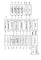
- the block diagram which shows the structure of a working machine controller.
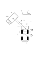
- Explanatory drawing which illustrates typically V shape work of a wheel loader.
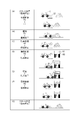
- Explanatory drawing which illustrates typically the work process of V shape work.
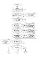
- the flowchart which shows the working machine control process of V shape work.
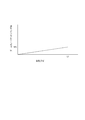
- the graph which shows the relationship between the movement distance in the reverse state of loading, and the target position of a working machine.
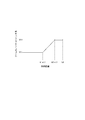
- the graph which shows the relationship between the movement distance in a load advance state, and the target position of a working machine.
- the graph which shows the relationship between the movement distance in an unreversed reverse state, and the target position of a working machine.
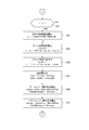
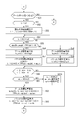
- the flowchart which shows the working machine control process in a cargo reverse state The flowchart which shows the work machine control process in a load advance state.
- the flowchart which shows the working machine control process in an unloaded reverse state The flowchart which shows the working machine control process in an unloaded reverse state.
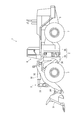
- FIG. 1 is a side view showing a wheel loader 1 according to an embodiment of the present invention.
- the wheel loader 1 is a large wheel loader 1 used in a mine or the like.
- the wheel loader 1 includes a vehicle body 2 composed of a front vehicle body 2A and a rear vehicle body 2B.
- a hydraulic pressure composed of an excavating / loading bucket 31, a boom 32, a bell crank 33, a connecting link 34, a bucket cylinder 35, a boom cylinder 36, and the like.
- a work machine 3 of the type is attached.
- the rear vehicle body 2B has a rear vehicle body frame 5 made of a thick metal plate or the like.
- a box-shaped cab 6 on which an operator enters is provided on the front side of the rear body frame 5, and an engine (not shown), a hydraulic pump driven by the engine, and the like are mounted on the rear side of the rear body frame 5.
- FIG. 2 is an explanatory diagram schematically showing a drive mechanism of the work machine 3.
- the wheel loader 1 includes a work machine controller 10, an engine 11, and a power take-off (PTO: power take-out device) 12.
- the PTO 12 distributes the output of the engine 11 to a traveling system that drives the wheels (tires) 7 and a hydraulic system that drives the work implement 3.
- the traveling system is a mechanism (traveling device) for causing the wheel loader 1 to travel, and includes a torque converter (T / C) 15, a transmission (not shown), an axle, and the like.
- the power output from the engine 11 is transmitted to the wheels 7 via the PTO 12, the torque converter 15, the transmission, and the axle.
- the hydraulic device system is a mechanism for mainly driving the work machine 3 (for example, the boom 32 and the bucket 31).
- the hydraulic system includes a hydraulic pump 21 for a work machine driven by the PTO 12, hydraulic pilot type bucket operation valves 22 and boom operation valves 23 provided in a discharge circuit of the hydraulic pump 21, and bucket operation valves 22.
- Electromagnetic proportional control valves for buckets 24 and 25 connected to the pilot pressure receiving unit and electromagnetic proportional control valves for booms 26 and 27 connected to each pilot pressure receiving unit of the boom operation valve 23 are provided.
- the electromagnetic proportional control valves 24 to 27 are connected to a pilot pump (not shown), and control the supply of hydraulic oil from the pilot pump to each pilot pressure receiving unit in accordance with a control signal from the work machine controller 10. Specifically, the electromagnetic proportional control valve 24 contracts the bucket cylinder 35 and switches the bucket operation valve 22 so that the bucket 31 moves to the loading position. Further, the electromagnetic proportional control valve 25 extends the bucket cylinder 35 and switches the bucket operation valve 22 so that the bucket 31 moves to the tilt position. The electromagnetic proportional control valve 26 switches the boom operation valve 23 so that the boom cylinder 36 is contracted and the boom 32 is lowered. Further, the electromagnetic proportional control valve 27 extends the boom cylinder 36 and switches the boom operation valve 23 so that the boom 32 is raised.
- the work machine controller 10 also includes a boom lever 41 and a bucket lever 42 provided on the cab 6, a semi-auto mode selection means 431 provided on a monitor 43 provided on the cab 6, and an approach length.
- a setting means 432, a boom angle sensor 44, a bucket angle sensor 45, a boom bottom pressure sensor 46, an engine controller 47, and a transmission controller 48 are connected.
- the boom lever 41 includes a lever angle sensor that detects a lever angle. When the operator operates the boom lever 41, the lever angle sensor detects a lever angle corresponding to the operation amount, and outputs it to the work machine controller 10 as a boom lever signal.
- the bucket lever 42 includes a lever angle sensor that detects a lever angle. When the operator operates the bucket lever 42, the lever angle sensor detects a lever angle corresponding to the operation amount, and outputs it to the work machine controller 10 as a bucket lever signal.
- the semi-auto mode selection means 431 displays a mode selection button on the monitor 43.
- an ON signal is output as the semi-auto mode selection signal, and the semi-auto loading mode is not selected.
- an OFF signal is output as a semi-auto mode selection signal.
- the approach length setting means 432 includes a moving distance L1 when moving backward in a state in which excavation of earth and sand is completed and a load of earth and sand is loaded on the bucket 31 in the V-shape work, After moving backward by the moving distance L1 and stopping, a moving distance L2 when moving toward the dump truck 60 is set.
- L is the total length of the wheel loader 1.
- the approach length setting means 432 displays “1” and “0.8” which are initial values of the approach lengths L1 and L2 on the monitor 43, and when the operator changes these numerical values, the input values are stored as set values. To the work machine controller 10.
- the boom angle sensor 44 includes, for example, a rotary encoder provided at a mounting portion (support shaft) of the boom 32 shown in FIG. 2 with respect to the vehicle body 2, and detects the boom angle between the center line of the boom 32 and the horizontal line. And outputs a detection signal. Accordingly, the boom angle sensor 44 constitutes a boom position detection means.
- the center line of the boom 32 is the YY line in FIG. 2, and the attachment portion (the center of the support shaft) of the boom 32 to the vehicle body 2 and the attachment portion of the bucket 31 (the center of the bucket support shaft). It is a connecting line. Therefore, when the YY line in FIG. 2 is along the horizontal line, the boom angle sensor 44 outputs a boom angle of 0 degrees. Further, when the tip of the boom 32 is raised from the state where the boom angle is 0 degrees, the boom angle sensor 44 outputs a positive value, and when the tip of the boom 32 is lowered, a negative value is output.
- the bucket angle sensor 45 is composed of, for example, a rotary encoder provided on the rotating shaft of the bell crank 33, and outputs 0 degrees when the blade edge of the bucket 31 is horizontal on the ground while the bucket 31 is grounded.
- a positive value is output
- the bucket angle sensor 45 constitutes a bucket position detection means.
- the boom bottom pressure sensor 46 detects the pressure on the bottom side of the boom cylinder 36. The boom bottom pressure increases when a load is loaded on the bucket 31 and decreases when the bucket 31 is empty.
- the engine controller 47 communicates with the work machine controller 10 via the Controller Area Network (CAN), and outputs engine operation information such as the rotation speed of the engine 11 to the work machine controller 10.
- the transmission controller 48 communicates with the work machine controller 10 via the CAN, and receives FR information indicating a selection state and a speed stage of the wheel loader 1 by the FR lever 49 and vehicle speed information output from the vehicle speed sensor 50. Output to the work machine controller 10.
- the vehicle speed sensor 50 is a sensor that detects the vehicle speed from the rotational speed of the drive shaft of the tire 7, and the vehicle speed information detected by the vehicle speed sensor 50 is output to the work machine controller 10 via the transmission controller 48.
- the work machine controller 10 includes a work state detection unit 110, a target setting unit 120, a movement distance detection unit 130, a work machine control unit 140, and a storage unit 150.
- the work state detection unit 110 includes a load determination unit 111 and a forward / backward determination unit 112.
- the load determination unit 111 determines whether or not a load is loaded in the bucket 31 based on the output value of the boom bottom pressure sensor 46.
- the forward / reverse determination means 112 determines whether the wheel loader 1 is in the forward movement state or the reverse movement state based on the FR information output from the transmission controller 48 according to the operation of the FR lever 49.
- the work state detection unit 110 detects the work state from the determination result of the load determination unit 111 and the determination result of the forward / reverse determination unit 112.
- the work state detection means 110 includes at least a wheel loader in a state where the excavation work is completed and the wheel loader 1 is moved backward, and a load state in order to carry the load to the dump truck 60 or the like.
- a load forward state in which 1 is moved forward and an unloaded reverse state in which the wheel loader 1 is moved backward after the load is loaded on the dump truck 60 or the like are detected.
- the target setting unit 120 sets the relationship between the movement distance of the wheel loader 1 and the target position of the work implement 3 according to the work state detected by the work state detection unit 110.
- a mathematical formula for calculating the target position of the work implement 3 specifically, the boom angle of the boom 32 and the bucket cylinder length of the bucket 31 is used.
- the relationship between the movement distance and the target position may be stored in a table structure.
- the movement distance detection means 130 receives vehicle speed information detected by the vehicle speed sensor 50 from the transmission controller 48 and calculates the current movement distance of the wheel loader 1.
- the work implement control means 140 outputs control signals for the electromagnetic proportional control valves 24 to 27 based on various pieces of input information, and operates the bucket 31 and the boom 32.
- the work machine controller 10 outputs an indicator command and a buzzer command to the monitor 43.
- the monitor 43 controls the display of the indicator 435 provided on the monitor 43 to notify the operator of information.
- the monitor 43 includes a buzzer 436 that sounds a warning sound. When a buzzer command is received, the monitor 43 sounds a warning sound by the buzzer 436 to warn the operator.
- the storage unit 150 stores various data input to the work machine controller 10 and stores various parameters necessary for controlling the work machine 3.
- V-shape work process Next, the V shape work by the wheel loader 1 will be described with reference to FIGS.
- the V shape work is performed by a plurality of work processes as described below.
- the operator advances the loaded wheel loader 1 toward the dump truck 60 as shown in FIG.
- the angle difference ⁇ between the direction of the wheel loader 1 at the stop position relative to the embankment and the direction toward the dump truck 60 is usually in the range of about 45 to 60 degrees.
- the moving distance to the dump truck 60 is set to L2 described above. The operator changes the direction by operating the steering, and advances the wheel loader 1 by the moving distance L2. When the wheel loader 1 reaches the side of the dump truck 60, the operator stops the wheel loader 1 by a brake operation.
- semi-automatic control that allows manual operation of the boom lever 41 and the bucket lever 42 by the operator during automatic control of the work machine 3 is further set. Specifically, the semi-automatic control is performed in each of the operation steps of FIG. 5C (C) Load reverse, (D) Load advance, and (F) Unload reverse.
- step S1 the lever operation commands (the boom lever operation command cmd_bm and the bucket lever operation command cmd_bk) are set to “0”.
- the variable sL indicating the starting distance is initialized to “0” in the load forward control and the idle reverse control (step S1).
- step S2 the work machine controller 10 determines whether or not the semi-automatic loading mode is “ON” based on the semi-automatic mode selection signal output from the semi-automatic mode selecting unit 431 (step S2).
- the semi-automatic loading mode is “OFF”
- the work machine controller 10 determines “NO” in step S2.
- the work machine controller 10 outputs an indicator command to the monitor 43, and when the indicator indicating that the semi-automatic loading mode is operating is displayed on the monitor 43, the indicator is erased (step S3).
- the work machine controller 10 repeats steps S1 to S3 until the semi-automatic loading mode is turned “ON”.
- Step S2 When the semi-automatic loading mode is “ON”, the work machine controller 10 determines YES in Step S2, outputs an indicator command to the monitor 43, and displays an indicator indicating that the semi-automatic loading mode is in operation on the monitor 43. (Step S4).
- the load determination unit 111 determines whether the load is in the loaded state or the empty state based on the boom bottom pressure sensor signal output from the boom bottom pressure sensor 46.
- the forward / reverse determination unit 112 determines whether the vehicle is moving forward or backward based on the FR information output from the transmission controller 48. From these pieces of information, the work state detection unit 110 can detect whether the wheel loader 1 is in the reverse load state, the forward load state, or the empty reverse state.
- the work state detection means 110 of the work machine controller 10 determines whether or not the backward movement detection has changed from OFF to ON (step S5).
- the work machine controller 10 determines “YES” in step S5 when it detects that the backward movement detection has changed from OFF to ON.
- the variable STAGE indicating the work stage is set to “2”
- the variable L indicating the movement distance is set to the initial value “0”
- the value of the current position is set in (cylinder length) (step S6).
- step S6 the work machine controller 10 sets the current boom angle based on the detection value of the boom angle sensor 44 to sp_bm, and sets the current bucket cylinder length to sp_bk based on the detection value of the bucket angle sensor 45. .
- step S7 the work state detection unit 110 of the work machine controller 10 determines whether or not it is detected that the load forward detection has changed from OFF to ON (step S7).
- the work implement controller 10 detects that the load advance detection has been turned ON and determines “YES” in step S7, the work implement controller 10 sets the variable STAGE indicating the work stage to “3” and the variable L indicating the movement distance. Is set to an initial value “0”, the current boom angle is set to sp_bm, and the current bucket cylinder length is set to sp_bk (step S8).
- step S9 the work state detection unit 110 of the work machine controller 10 determines whether or not it has been detected that the detection of the backward movement of the unloaded state has changed from OFF to ON (step S9).
- the work implement controller 10 detects that the unloading reverse detection has changed to ON and determines “YES” in step S9, the work implement controller 10 sets the variable STAGE indicating the work stage to “4” and sets the variable indicating the movement distance. L is set to an initial value “0”, the current boom angle is set to sp_bm, and the current bucket cylinder length is set to sp_bk (step S10).
- End condition judgment The work machine controller 10 determines whether or not the end condition is satisfied after performing the initial setting in steps S6, S8, and S10 or when it is determined NO in step S9 (step S11).
- the end condition is satisfied when any of the following six conditions is satisfied.
- End condition 1 is a case where the semi-auto mode is disabled by the output of the semi-auto mode selection means 431 of the monitor 43.
- Termination condition 2 is when the work state detection means 110 detects either an unloading advance or an excavation state.
- the empty forward state can be determined by the boom bottom pressure sensor signal and the FR information
- the excavation state can be determined by the boom bottom pressure sensor signal, the boom angle, the bucket cylinder length, and the like.
- Termination condition 3 is when the lever speed stage is F3 (forward 3rd speed) or higher. While the wheel loader 1 is in the V-shape work, the lever speed stage is selected only up to F2, and is set to F3 to indicate that the wheel loader 1 is not working and is traveling.
- the end condition 4 is when the work machine 3 is in a locked state.
- the wheel loader 1 is provided with a lock button so that the work implement 3 does not operate during traveling, and when the lock button is operated by the operator, it can be determined that the vehicle is not traveling but traveling. is there.
- End condition 5 refers to a case where the sensor or the electromagnetic proportional control valves (EPC valves) 24 to 27 have a failure to end the semi-auto mode with reference to FMEA (Failure Mode and Effect Analysis).
- the end condition 6 is a case where the engine is in the stopped state in the engine operating state input from the engine controller 47.
- the work machine controller 10 determines YES in step S11. In this case, the work machine controller 10 sets the value of STAGE to “1” indicating that it is in a standby state, and further outputs a buzzer command to the monitor 43 when a condition other than the end condition 2 is met, and sounds an abnormal end buzzer. (Step S13). Then, the work machine controller 10 returns to the process of step S1 and continues the process.
- the relationship between the moving distance of the wheel loader 1 and the target position of the work implement 3 is set according to each work state. Specifically, the target position of the work machine 3 when the wheel loader 1 moves a preset distance is set. Examples of the target position of the work machine 3 are shown in Tables 1 and 2, and the relationship between the movement distance set in Tables 1 and 2 and the target position is shown in FIGS.
- the parameters set in Tables 1 and 2 are stored in the storage unit 150 of the work machine controller 10.
- the boom angle raising positioner position and the lowering positioner position are boom angles set by the operator.
- the position of the bucket cylinder length is set to a position where the bucket angle becomes 0 degrees when the boom 32 is lowered and the bucket 31 is grounded.
- the bucket cylinder length is A2 when the high lift boom 32 is mounted, and B2 when the standard boom 32 is mounted.
- the operator can set the work machine 3 to continue to move in proportion to the moving distance in order to move the wheel loader 1 linearly without turning the steering.
- TP2 is set so that the boom angle is raised to the positioner position.
- the raising positioner position is set by the operator according to the height of the vessel 61 of the dump truck 60 on which the wheel loader 1 loads a load such as earth and sand.
- the bucket cylinder length is set so that the load in the bucket 31 is not spilled by maintaining the bucket 31 in the lift position when the boom angle changes.
- the operator operates the steering in the direction toward the dump truck 60 until the wheel loader 1 moves by the distance K1 ⁇ L2, so it is desirable to maintain the position of the work implement 3.
- the work implement 3 is raised to the positioner position before moving from the distance K1 ⁇ L2 to the distance K2 ⁇ L2, and the work implement 3 is raised and maintained at the positioner position until it moves from the distance K2 ⁇ L2 to L2.
- the bucket 31 can be prevented from interfering with the vessel 61.
- TP3 has no boom angle operation.
- the bucket cylinder length is set to a position where the bucket angle becomes 0 degrees when the bucket 31 is in the positioner position, that is, when the boom 32 is lowered and the bucket 31 is grounded.
- the boom angle is 0 degree
- the bucket cylinder length is the positioner position.
- the boom angle is the lowered positioner position
- the bucket cylinder length is the positioner position.
- the work machine controller 10 determines whether or not the movement distance L obtained by the movement distance detection means 130 is less than the set value L1 (step S21). [Current distance calculation] If the work machine controller 10 determines “YES” in step S21, the working distance detector 130 calculates the current moving distance L (step S22). The current moving distance L is obtained by ⁇ (abs (V) * 1000/3600 * ⁇ t). V is a vehicle speed (km / h), and is converted to a second speed (m / s) by multiplying by 1000/3600.
- ⁇ t is a program execution cycle (sec) in the work machine controller 10 and is, for example, 0.01 sec. If it is determined “NO” in step S21, the work machine controller 10 does not calculate the current movement distance L in step S22 because the movement of the distance L1 has already been completed.
- the target setting means 120 of the work machine controller 10 calculates the boom target position after the process of step S22 or when it is determined “NO” in step S21 (step S23).
- the angle of the boom 32 is controlled in proportion to the movement distance.
- the boom target position tp_bm (t) at the movement distance L is obtained by L / L1 * (TP1_bm-sp_bm) + sp_bm.
- TP1_bm is the boom angle at the target position TP1
- sp_bm is the start position of the boom 32 set in step S6.
- the boom target position tp_bm (t) is obtained by adding the start position, which is an initial value, to a value obtained by multiplying the ratio of the movement distance L to the set distance L1 and the difference between the target position and the start position of the boom 32. It is done.
- the target setting means 120 of the work machine controller 10 calculates the bucket target position after the process of step S23 (step S24).
- the bucket target position is obtained in the same way as the boom target position. That is, in the backward movement operation of the load, as described above, the angle of the boom 32 is controlled in proportion to the moving distance. Specifically, as described in Table 2, the bucket angle is set corresponding to the boom angle, and the bucket cylinder length is also set corresponding to the bucket angle. Therefore, the cylinder length of the bucket cylinder 35 that moves the bucket 31 is also controlled in conjunction with the angle of the boom 32.
- the bucket target position tp_bk (t) at the movement distance L is obtained by L / L1 * (TP1_bk ⁇ sp_bk) + sp_bk.
- TP1_bk is the bucket cylinder length at the target position TP1
- sp_bk is the start position of the bucket 31 set in step S6. That is, the bucket target position tp_bk (t) is obtained by adding the start position, which is an initial value, to a value obtained by multiplying the ratio of the movement distance L to the set distance L1 by the difference between the target position and the start position of the bucket 31. It is done.
- the target setting means 120 uses the bucket cylinder position when the wheel loader moves the distance L1 as the bucket target position tp_bk (t) at the movement distance L from the bucket cylinder length at the start of movement in the reverse load state.
- the bucket cylinder length proportional to the travel distance is set up to the bucket cylinder length. That is, the target setting means 120 sets the bucket cylinder length that maintains the bucket 31 in the tilt position in conjunction with the boom angle.
- the work implement control means 140 of the work implement controller 10 includes the actual boom angle detected by the boom angle sensor 44, the actual bucket cylinder length detected based on the detection value of the bucket angle sensor 45, the target The amount of deviation from the position is calculated (step S25). That is, the boom target deviation angle ⁇ bm is obtained by boom target position tp_bm (t) ⁇ actual boom angle BmAngle, and the bucket target deviation length ⁇ bk is obtained by bucket target position tp_bk (t) ⁇ actual bucket cylinder length BkLength.
- the work machine control means 140 of the work machine controller 10 calculates a boom lever operation command cmd_bm after the process of step S25 (step S26).
- the boom lever operation command cmd_bm is used to command the flow rate of hydraulic oil in the electromagnetic proportional control valves 26 and 27 in the range of ⁇ 100% to + 100%, and the auto boom command based on the boom target deviation angle ⁇ bm obtained in step S25.
- the boom lever command BmLever that is input when the operator is operating the boom lever 41.
- the auto boom command is a function interp ( ⁇ bm, BmCmdFlow, DeltaBmAngle) for obtaining a target flow rate corresponding to the boom target deviation angle ⁇ bm from a boom flow rate table BmCmdFlow that defines the relationship between the boom deviation angle and the target flow rate shown in FIG. ).
- the boom lever command is added to the auto boom command (%).
- the target flow rate is reduced to about ⁇ 20 to + 20%, and the moving speed of the boom 32 is also lowered.
- the value of the target flow rate can be increased, so that the moving speed of the boom 32 can be improved.
- the work machine control means 140 of the work machine controller 10 calculates the bucket lever operation command cmd_bk after the process of step S26 (step S27).
- the bucket lever operation command cmd_bk commands the flow rate of hydraulic oil in the electromagnetic proportional control valves 24 and 25 in the range of ⁇ 100% to + 100%, and is an auto bucket command based on the bucket target deviation length ⁇ bk obtained in step S25.
- the bucket lever command BkLever that is input when the operator is operating the bucket lever 42.
- the auto bucket command is a function interp ( ⁇ bk, BkCmdFlow, DeltaBmLength) for obtaining a target flow rate corresponding to the bucket target deviation length ⁇ bk from the bucket flow rate table BkCmdFlow that defines the relationship between the bucket deviation length and the target flow rate shown in FIG. ).
- the bucket lever command is added to the auto bucket command (%).
- the target flow rate is reduced to about ⁇ 20 to + 20%, and the moving speed of the bucket 31 is also lowered.
- the value of the target flow rate can be increased, so that the moving speed of the bucket 31 can be improved.
- the boom lever operation command cmd_bm and bucket lever operation command cmd_bk obtained in steps S26 and S27 are input to the electromagnetic proportional control valves 24 to 26 from the work implement control means 140, whereby the bucket operation valve 22, the boom operation valve 23 is controlled, the bucket cylinder 35 and the boom cylinder 36 are operated, and the work implement 3 moves.
- step S27 the work machine controller 10 returns to FIG. 6 and executes step S5 and subsequent steps again.
- NO is determined in step S5
- NO is also determined in other steps S7 and S9, and NO in step S11. Since it is determined as “2” in step S12, the reverse load control shown in FIG. 10 is repeatedly executed.
- the work machine 3 is set to move to the target position TP1 when the movement distance becomes L1, but when the operator's lever operation is added, The working machine 3 may reach the target position TP1 before the moving distance becomes L1.
- step S25 After the work implement 3 moves to the target position TP1, the deviation amount obtained in step S25 becomes 0, so the work implement 3 is maintained at the target position TP1.
- the accelerator operation and the steering operation are performed by the operator, if the traveling speed is made much faster than usual by the accelerator operation, the supply flow rate of hydraulic oil to the work machine cannot catch up, and before the work machine 3 finishes moving. There is also a possibility that the movement of the distance L1 is completed. In this case, after the movement of the wheel loader 1 is completed, only the work machine 3 moves.
- FIG. 11 shows a processing flow of the load forward control.
- the work machine controller 10 determines whether or not the movement distance L obtained by the movement distance detection unit 130 is less than the set value L2 (step S31).
- the movement distance detection unit 130 calculates the current movement distance by the same method as in step S22 (step S32).
- step S32 the work machine controller 10 does not calculate the current movement distance L in step S32 because the movement of the distance L2 has already been completed.
- the work machine controller 10 determines whether the movement distance L is equal to or greater than K1 ⁇ L2 and less than K2 ⁇ L2 after the process of step S32 or when “NO” is determined in step S31 (step S31). S33).
- the work machine controller 10 determines NO in step S33. For example, if the distance coefficient K1 is 0.5, and before the moving distance L1 reaches half of the set distance L2, the work machine controller 10 determines NO in step S33.
- step S33 If the target setting means 120 of the work machine controller 10 determines NO in step S33, it substitutes the actual boom angle BmAngle for the boom target position tp_bm (t) (step S34), and the actual bucket cylinder for the bucket target position tp_bk (t).
- the length BkLength is substituted (step S35). That is, the target setting unit 120 sets the boom target position and the bucket target position to the current position. Therefore, in the deviation amount calculation process (step S39), which is the same process as step S25 described above, the boom target deviation angle ⁇ bm is obtained by the boom target position tp_bm (t) ⁇ the actual boom angle BmAngle, and the bucket target deviation length ⁇ bk is determined by the bucket.
- each deviation amount is “0”. Accordingly, in the boom lever operation command calculation process (step S40) and the bucket lever operation command calculation process (step S41), which are the same processes as steps S26 and S27 described above, since the deviation amount is 0, the auto boom command and the auto bucket The command is 0% flow rate. For this reason, only when the boom lever 41 and the bucket lever 42 are manually operated, the flow rate corresponding to the boom lever command and the bucket lever command is calculated as each operation command.
- the work implement 3 is maintained at TP1 in the automatic control by the work implement controller 10, but when the operator manually operates, depending on the operation Thus, the work machine 3 can be moved.
- the work machine controller 10 determines “YES” in step S33, that is, if the movement distance L is equal to or greater than K1 ⁇ L2 and less than K2 ⁇ L2, whether the start distance sL is set to K1 ⁇ L2. (Step S36). If the determination is “NO” in step S36, the work machine controller 10 sets K1 ⁇ L2 (first intermediate distance) to the starting distance sL, and sets sp_bm to the boom at the time of the current movement, that is, the first intermediate distance. An angle is set and the bucket cylinder length at the time of the first intermediate distance movement is set in sp_bk (step S36A).
- the boom target position tp_bm (t) at the movement distance L is obtained by (L ⁇ sL) / (L2 * (K2 ⁇ K1)) * (TP2_bm ⁇ sp_bm) + sp_bm.
- TP2_bm is the boom angle at the target position TP2
- sp_bm is the start position of the boom 32 lifting control set in step S36A.
- L-sL is the moving distance from the point of K1 ⁇ L2 (first intermediate distance)
- (L2 * (K2-K1)) is the point of K2 ⁇ L2 (second intermediate distance) from the point of K1 ⁇ L2 It is the distance to.
- the boom target position tp_bm (t) is the ratio of the travel distance from the point K1 ⁇ L2 to the distance (L2 * (K2-K1)) from the point K1 ⁇ L2 to the point K2 ⁇ L2 (L-sL ) And the difference between the target position and start position of the boom 32 (TP2_bm-sp_bm) and the start position (sp_bm) that is the initial value is added.
- the target setting means 120 of the work machine controller 10 calculates the bucket target position, similarly to step S24 (step S38). That is, the bucket target position tp_bk (t) at the movement distance L is obtained by (L ⁇ sL) / (L2 * (K2 ⁇ K1)) * (TP2_bk ⁇ sp_bk) + sp_bk. Therefore, the target setting means 120 moves the first intermediate distance as the target position of the boom corresponding to the load advancement state when the movement distance is not less than the first intermediate distance and less than the second intermediate distance.
- the boom angle is set in proportion to the moving distance from the boom angle at the time point to the boom angle at which the boom 32 is set to the preset position position when the second intermediate distance is moved.
- the target setting means 120 tilts the bucket 31 when the bucket 31 moves from the bucket cylinder length at the time when the first intermediate distance is moved to the second intermediate distance as the bucket target position according to the load advance state.
- the bucket cylinder length is set in proportion to the moving distance up to the bucket cylinder length as the position. That is, the target setting means 120 sets the bucket cylinder length that maintains the bucket 31 in the tilt position in conjunction with the boom angle.
- the work implement control means 140 of the work implement controller 10 calculates the deviation amount between the actual boom angle, bucket cylinder length, and the target position after step S35 or step S38, as in step S25 (step S39). .
- the work machine control means 140 of the work machine controller 10 calculates the boom lever operation command cmd_bm (step S40) and the bucket lever operation command cmd_bk (step S41) after the process of step S39.
- the process in step S40 is the same as that in step S26, and the process in step S41 is the same as that in step S27. Therefore, the description thereof is omitted.
- the boom lever operation command cmd_bm and the bucket lever operation command cmd_bk obtained in steps S40 and S41 are input from the work implement control means 140 to the electromagnetic proportional control valves 24 to 26, whereby the bucket operation valve 22, the boom operation valve 23 is controlled, the bucket cylinder 35 and the boom cylinder 36 are operated, and the work implement 3 moves.
- the work machine controller 10 returns to FIG. 6 after the process of step S41, and executes step S5 and subsequent steps again.
- the load advancement detection is already ON, so it is determined NO in step S7, NO is also determined in other steps S5 and S9, and NO in step S11. Since it is determined as “3” in step S12, the load forward control shown in FIG. 11 is repeatedly executed.
- FIG. 12 and FIG. 13 show the processing flow of the unreversed reverse control.
- the work machine controller 10 compares the boom bottom pressure with the set value A (kg) to confirm whether the load is “empty” (step S51). Since the boom bottom pressure is not less than the set value A, when the work implement controller 10 detects NO (loaded state) in step S51, the work implement controller 10 ends the unloaded reverse control and returns to FIG. As a result, it is possible to prevent the boom 32 from being lowered in the loaded state.
- step S51 the work machine controller 10 determines whether or not the movement distance L obtained by the movement distance detection means 130 is less than the set value L2 (step S52).
- step S52 the movement distance detection means 130 calculates the current movement distance L by the same method as steps S22 and S32 (step S53). If it is determined “NO” in step S52, the work machine controller 10 does not calculate the current movement distance L in step S53 because the movement of the distance L2 has already been completed.
- the work machine controller 10 determines whether or not the movement distance L is less than K3 ⁇ L2 (third intermediate distance) after the process of step S52 or when “NO” is determined in step S52 (step S54). ).
- K3 is 0.2
- the work machine controller 10 determines YES in step S54.
- the target setting unit 120 of the work machine controller 10 determines YES in step S54, it determines whether or not the deviation length between the actual bucket cylinder length BkLength and the bucket target position TP3_bk is greater than a set value (for example, 10 mm). Determination is made (step S55).
- the work implement target TP3 for the unloading reverse control is that the boom 32 is not operated and only the bucket 31 is moved to the positioner position. Since the bucket 31 immediately after loading is in the loading position and different from the positioner position, the work machine controller 10 determines YES in step S55.
- the target setting unit 120 of the work machine controller 10 determines YES in step S55, it calculates a boom target position (step S56) and a bucket target position (step S57).
- the target setting means 120 substitutes the actual boom angle BmAngle for the boom target position tp_bm (t) in step S56 (step S56).
- the target setting means 120 determines that the bucket 31 is set in advance at the initial position (this embodiment) when the wheel loader 1 moves the third intermediate distance from the bucket cylinder length at the start of the movement in the idle reverse state.
- the bucket cylinder length is set in proportion to the moving distance up to the bucket cylinder length which becomes the positioner position).
- the target setting means 120 of the work machine controller 10 determines NO in step S55 when the deviation length between the absolute value of the actual bucket cylinder length BkLength and the bucket target position TP3_bk becomes smaller than 10 mm. In this case, since the bucket 31 has moved to the approximate positioner position, the work machine controller 10 does not need to move the bucket 31 any more. Therefore, the target setting means 120 substitutes the actual boom angle BmAngle for the boom target position tp_bm (t) (step S58) and sets the actual bucket cylinder length BkLength for the bucket target position tp_bk (t), as in steps S34 and S35. Substitute (step S59).
- Step S68 An amount calculation process (step S68), a boom lever operation command calculation process (step S69), and a bucket lever operation command calculation process (step S70) are executed.
- step S68 An amount calculation process
- step S69 a boom lever operation command calculation process
- step S70 a bucket lever operation command calculation process
- the work machine controller 10 determines NO in steps S54 and S64, and step S60. It determines with YES.
- step S61 determines whether or not the start distance sL is set to K3 ⁇ L2 (step S61). If it is determined “NO” in step S61, the work machine controller 10 sets K3 ⁇ L2 to the starting distance sL, sets the current boom angle to sp_bm, and sets the current bucket cylinder length to sp_bk. Set (step S61A). For this reason, the work machine controller 10 executes step S61A only once as well as step S36A. Next, the work machine controller 10 calculates the boom target position in the same manner as in Step S37 (Step S62). Here, as shown in FIG.
- the boom target position tp_bm (t) at the movement distance L is obtained by (L ⁇ sL) / (L2 * (K4 ⁇ K3)) * (TP4_bm ⁇ sp_bm) + sp_bm.
- TP4_bm is a boom angle at the target position TP4, and the boom angle is set to be horizontal, that is, 0 degrees.
- sp_bm is the control start position for lowering the angle of the boom 32 set in step S61A.
- L-sL is the moving distance from the point K3 ⁇ L2
- (L2 * (K4-K3)) is the distance from the point K3 ⁇ L2 to the point K4 ⁇ L2. That is, the boom target position tp_bm (t) is the ratio of the moving distance from the point K3 ⁇ L2 to the distance from the point K3 ⁇ L2 to the point K4 ⁇ L2, and the difference between the target position of the boom 32 and the control start position.
- the target setting means 120 sets the boom 32 at the time when the fourth intermediate distance is moved from the boom angle when the third intermediate distance is moved as the target position of the boom 32 according to the idle reverse state.
- the boom angle is set in proportion to the movement distance until the boom angle becomes horizontal.
- the work machine controller 10 calculates the bucket target position in the same manner as in Step S38 (Step S63). That is, the bucket target position tp_bk (t) at the movement distance L is obtained by (L-sL) / (L2 * (K4-K3)) * (TP4_bk-sp_bk) + sp_bk.
- the target setting means 120 sets the bucket cylinder length for maintaining the bucket 31 at a preset initial position (positioner position in the present embodiment) as the target position of the bucket 31 according to the idle reverse state. Set.
- the work machine controller 10 performs the processes of steps S68 to S70 after the process of step S63.
- the work machine controller 10 determines NO in steps S54 and S60, and determines YES in step S64.
- step S64 determines that the start distance sL is set to K4 ⁇ L2 similarly to the step S61 (step S65).
- step S65 determines “NO” in step S65, it sets K4 ⁇ L2 to the starting distance sL, sets the current boom angle to sp_bm, and sets the current bucket cylinder length to sp_bk. Set (step S65A). For this reason, the work machine controller 10 executes step S65A only once as in steps S36A and S61A.
- step S66 calculates the boom target position in the same manner as in step S62 (step S66).
- TP5_bm is a boom angle at the target position TP5, and is set to a lowered positioner position that can be set by the operator.
- sp_bm is the control start position of the boom 32 set in step S65A, and is the position of the target value TP4 if automatic control is performed.
- L-sL is the moving distance from the point of K4 ⁇ L2
- (L2 * (1-K4)) is the distance from the point of K4 ⁇ L2 to the point of L2. That is, the boom target position tp_bm (t) is a ratio of the moving distance from the point K4 ⁇ L2 to the distance from the point K4 ⁇ L2 to the point L2, and the difference between the target position of the boom 32 and the control start position. The initial value of the control start position is added to the multiplied value.
- the target setting means 120 determines that the boom 32 at the time of moving the second distance L2 from the boom angle at the time of moving the fourth intermediate distance as the target position of the boom 32 according to the reverse travel state.
- the boom angle is set in proportion to the movement distance up to the horizontal boom angle.
- the work machine controller 10 calculates the bucket target position in the same manner as in Step S63 (Step S67). That is, the bucket target position tp_bk (t) at the movement distance L is obtained by (L-sL) / (L2 * (1-K4)) * (TP5_bk-sp_bk) + sp_bk.
- the target setting means 120 sets the bucket cylinder length for maintaining the bucket 31 at a preset initial position (positioner position in the present embodiment) as the target position of the bucket 31 according to the idle reverse state. Set.
- the work machine controller 10 performs the processes of steps S68 to S70 after the process of step S67. By repeating the above control, the V shape operation can be repeated.
- the work machine controller 10 realizes semi-automatic control in the backward work of loading, the forward work of loading, and the backward work of empty load. Therefore, the operator manually operates the boom lever 41 and the bucket lever 42 during the automatic control of the work machine 3. Can intervene. For this reason, an operator's intention can be reflected in the movement of the work machine 3. For example, the work machine 3 can be moved at a higher speed, and the operability can be improved.
- the present invention is not limited to the above-described embodiments, and modifications, improvements, and the like within the scope that can achieve the object of the present invention are included in the present invention.
- the semi-automatic control of the present invention is executed in the case of the backward load operation, the forward load operation, and the empty reverse operation.
- the present invention is applied to only one or only two of these operations. It is possible to perform semi-automatic control.
- the relationship between the moving distance of the wheel loader 1 and the target position of the work implement 3 in each work is not limited to that shown in FIGS.
- the work implement 3 in the reverse load control, the work implement 3 may be set to move to the target position TP1 when it has moved to an intermediate position less than the movement distance L1.
- the boom 32 In the forward load control, the boom 32 is gently moved to the new target position set between the target positions TP1 and TP2 without being maintained at the target position TP1 during the movement of the first intermediate distance (K1 ⁇ L2). It may be raised.
- the work implement 3 may be moved to the lowered positioner position when moving to the fourth intermediate distance (K4 ⁇ L2), and thereafter the work implement 3 may be maintained at the position of TP5. .
- the operator may be able to set the relationship between the moving distance of the wheel loader 1 corresponding to each work and the target position of the work implement 3.
- numerical values of the distance coefficients K1 to K4 are displayed on the monitor 43, and the numerical values are changed by the operator and stored in the storage means 150, so that the moving distance of the wheel loader 1 corresponding to each work and the working machine 3
- the operator may change the relationship with the target position.
- the present invention is semi-automatic control that allows manual operation of the boom lever 41 and the bucket lever 42, the distance that the work implement 3 has reached the target position by manual operation is stored in the storage unit 150 and stored in the storage unit 150.
- the operator may change the relationship between the moving distance of the wheel loader 1 corresponding to each work and the target position of the work implement 3 by changing the numerical values of the distance coefficients K1 to K4 according to the stored distance. For example, in the load forward control, since K1 is 0.5, the work implement 3 is maintained at the target position TP1 until the wheel loader 1 moves to the intermediate point of L2, but the operator moves to the intermediate point. For example, when the work machine 3 is moved toward the target position TP2 by operating the boom lever 41 at a point of 0.4 ⁇ L2, the distance coefficient K1 is set to 0.4. That's fine. Thereby, at the time of semi-automatic control of the work machine 3, it is possible to realize control reflecting the operation preference of each operator.
- the semi-automatic control in which the manual operation by the boom lever 41 or the bucket lever 42 can be intervened during the control of the work machine 3, but the fully automatic operation in which the manual operation is not intervened in the control of the work machine 3 is described.
- Control may be used, or semi-automatic control and automatic control may be selected.
- a mode that does not involve manual operation may be selected.
- the target moving distance of the wheel loader 1, the actual moving distance, the target position of the work implement 3, the actual position, and the like may be displayed on the monitor 43 during semi-automatic control to support the operator.
- load discrimination means 112 ... forward / reverse discrimination means, 120 ... target setting means, 130 ... Moving distance detection means, 140 ... work machine control means, 150 ... storage means, 431 Semi-automatic mode selection means, 432 ... approach length setting means, 435 ... indicator, 436 ... buzzer.
Landscapes
- Engineering & Computer Science (AREA)
- Mining & Mineral Resources (AREA)
- Civil Engineering (AREA)
- General Engineering & Computer Science (AREA)
- Structural Engineering (AREA)
- Mechanical Engineering (AREA)
- Operation Control Of Excavators (AREA)
Priority Applications (9)
| Application Number | Priority Date | Filing Date | Title |
|---|---|---|---|
| CN201580000326.7A CN105143560A (zh) | 2015-03-25 | 2015-03-25 | 轮式装载机 |
| PCT/JP2015/059222 WO2015129932A1 (ja) | 2015-03-25 | 2015-03-25 | ホイールローダ |
| US14/767,475 US20160281323A1 (en) | 2015-03-25 | 2015-03-25 | Wheel Loader |
| JP2015528796A JPWO2015129932A1 (ja) | 2015-03-25 | 2015-03-25 | ホイールローダ |
| EP16768897.7A EP3176332B1 (de) | 2015-03-25 | 2016-03-24 | Radlader |
| PCT/JP2016/059451 WO2016152994A1 (ja) | 2015-03-25 | 2016-03-24 | ホイールローダ |
| CN201680002502.5A CN106661858B (zh) | 2015-03-25 | 2016-03-24 | 轮式装载机 |
| US15/514,401 US10876270B2 (en) | 2015-03-25 | 2016-03-24 | Wheel loader |
| JP2017508435A JP6619799B2 (ja) | 2015-03-25 | 2016-03-24 | ホイールローダ |
Applications Claiming Priority (1)
| Application Number | Priority Date | Filing Date | Title |
|---|---|---|---|
| PCT/JP2015/059222 WO2015129932A1 (ja) | 2015-03-25 | 2015-03-25 | ホイールローダ |
Publications (1)
| Publication Number | Publication Date |
|---|---|
| WO2015129932A1 true WO2015129932A1 (ja) | 2015-09-03 |
Family
ID=54009238
Family Applications (2)
| Application Number | Title | Priority Date | Filing Date |
|---|---|---|---|
| PCT/JP2015/059222 Ceased WO2015129932A1 (ja) | 2015-03-25 | 2015-03-25 | ホイールローダ |
| PCT/JP2016/059451 Ceased WO2016152994A1 (ja) | 2015-03-25 | 2016-03-24 | ホイールローダ |
Family Applications After (1)
| Application Number | Title | Priority Date | Filing Date |
|---|---|---|---|
| PCT/JP2016/059451 Ceased WO2016152994A1 (ja) | 2015-03-25 | 2016-03-24 | ホイールローダ |
Country Status (5)
| Country | Link |
|---|---|
| US (2) | US20160281323A1 (de) |
| EP (1) | EP3176332B1 (de) |
| JP (2) | JPWO2015129932A1 (de) |
| CN (2) | CN105143560A (de) |
| WO (2) | WO2015129932A1 (de) |
Cited By (10)
| Publication number | Priority date | Publication date | Assignee | Title |
|---|---|---|---|---|
| EP3156548A1 (de) * | 2015-10-15 | 2017-04-19 | J.C. Bamford Excavators Limited | Verfahren zur bereitstellung eines alarms |
| WO2017126182A1 (ja) * | 2016-10-28 | 2017-07-27 | 株式会社小松製作所 | 積込機械の制御システム及び積込機械の制御方法 |
| DE112016000719T5 (de) | 2016-11-09 | 2018-08-09 | Komatsu Ltd. | Arbeitsfahrzeug und Verfahren zur Kalibrierung von Daten |
| WO2019168012A1 (ja) * | 2018-02-28 | 2019-09-06 | 株式会社小松製作所 | 積込機械の制御装置および制御方法 |
| US10570582B2 (en) | 2016-11-23 | 2020-02-25 | Caterpillar Inc. | System and method for operating a material-handling machine |
| JP2020165108A (ja) * | 2019-03-28 | 2020-10-08 | 日立建機株式会社 | 作業車両 |
| WO2020203596A1 (ja) * | 2019-04-04 | 2020-10-08 | 株式会社小松製作所 | 作業機械を含むシステム、コンピュータによって実行される方法、学習済みの姿勢推定モデルの製造方法、および学習用データ |
| WO2024043074A1 (ja) * | 2022-08-24 | 2024-02-29 | 株式会社小松製作所 | 作業機械、作業機械を含むシステム、および作業機械の制御方法 |
| WO2024043075A1 (ja) * | 2022-08-24 | 2024-02-29 | 株式会社小松製作所 | 作業機械、作業機械を含むシステム、および作業機械の制御方法 |
| US20240410128A1 (en) * | 2021-11-02 | 2024-12-12 | Kobelco Construction Machinery Co., Ltd. | Load discharge system |
Families Citing this family (40)
| Publication number | Priority date | Publication date | Assignee | Title |
|---|---|---|---|---|
| CN105544632B (zh) * | 2016-01-29 | 2017-09-29 | 徐工集团工程机械股份有限公司科技分公司 | 一种用于控制装载机铲斗自动放平的系统 |
| JP6552996B2 (ja) * | 2016-06-07 | 2019-07-31 | 日立建機株式会社 | 作業機械 |
| WO2017086488A1 (ja) * | 2016-11-29 | 2017-05-26 | 株式会社小松製作所 | 建設機械の制御装置及び建設機械の制御方法 |
| KR102459514B1 (ko) * | 2017-03-31 | 2022-10-27 | 현대두산인프라코어 주식회사 | 건설기계의 제어 장치 및 건설기계의 제어 방법 |
| EP3450634B1 (de) | 2017-08-30 | 2021-03-03 | Topcon Positioning Systems, Inc. | Verfahren und vorrichtung zur maschinenbedienerbefehlsdämpfung |
| US11293168B2 (en) | 2018-02-28 | 2022-04-05 | Deere & Company | Method of limiting flow through accelerometer feedback |
| US10954650B2 (en) | 2018-02-28 | 2021-03-23 | Deere & Company | Hydraulic derate stability control |
| US10954654B2 (en) | 2018-02-28 | 2021-03-23 | Deere & Company | Hydraulic derate stability control and calibration |
| US11525238B2 (en) * | 2018-02-28 | 2022-12-13 | Deere & Company | Stability control for hydraulic work machine |
| US10648154B2 (en) | 2018-02-28 | 2020-05-12 | Deere & Company | Method of limiting flow in response to sensed pressure |
| US10829907B2 (en) | 2018-02-28 | 2020-11-10 | Deere & Company | Method of limiting flow through sensed kinetic energy |
| JP6946226B2 (ja) * | 2018-03-29 | 2021-10-06 | 株式会社小松製作所 | 作業車両の制御システム、方法、及び作業車両 |
| JP7141843B2 (ja) * | 2018-03-30 | 2022-09-26 | 株式会社小松製作所 | 作業機械の制御装置及び作業機械の制御方法 |
| CN108505579B (zh) * | 2018-04-25 | 2023-08-18 | 山东临工工程机械有限公司 | 挖掘机电控开式节流液压系统 |
| JP7175666B2 (ja) * | 2018-07-31 | 2022-11-21 | 株式会社小松製作所 | 指標値特定装置および指標値特定方法 |
| US11512447B2 (en) | 2018-11-06 | 2022-11-29 | Deere & Company | Systems and methods to improve work machine stability based on operating values |
| KR102785874B1 (ko) | 2019-02-04 | 2025-03-21 | 스미도모쥬기가이고교 가부시키가이샤 | 쇼벨 |
| EP3926103B1 (de) * | 2019-02-15 | 2025-10-29 | Sumitomo Heavy Industries, Ltd. | Bagger |
| CN113366210B (zh) * | 2019-04-04 | 2023-07-14 | 株式会社小松制作所 | 作业车辆、作业车辆的控制装置、以及作业车辆的控制方法 |
| CN110206090A (zh) * | 2019-04-28 | 2019-09-06 | 江苏徐工工程机械研究院有限公司 | 一种装载机铲装作业挡位控制方法、装置及系统 |
| CN110306622A (zh) * | 2019-06-18 | 2019-10-08 | 江苏徐工工程机械研究院有限公司 | 一种装载机工作装置举升高度自动控制方法、装置及系统 |
| CN110331757A (zh) * | 2019-07-18 | 2019-10-15 | 江苏徐工工程机械研究院有限公司 | 装载机铲斗举升控制方法、系统和控制器 |
| US11408449B2 (en) * | 2019-09-27 | 2022-08-09 | Topcon Positioning Systems, Inc. | Dithering hydraulic valves to mitigate static friction |
| US11828040B2 (en) | 2019-09-27 | 2023-11-28 | Topcon Positioning Systems, Inc. | Method and apparatus for mitigating machine operator command delay |
| AU2019240588B2 (en) | 2019-10-01 | 2021-05-06 | Caterpillar Inc. | Method and system for operating implement assemblies of machines |
| EP3907332B1 (de) * | 2020-05-06 | 2023-03-01 | Sandvik Mining and Construction Oy | Antriebsregelung bei ladevorgängen einer bergbaumaschine |
| JP7354978B2 (ja) | 2020-09-29 | 2023-10-03 | コベルコ建機株式会社 | アタッチメントの目標軌跡変更システム |
| US11946230B2 (en) * | 2020-10-28 | 2024-04-02 | Deere & Company | Container load assist system and method for a work vehicle |
| JP7534936B2 (ja) * | 2020-11-27 | 2024-08-15 | 株式会社小松製作所 | ホイールローダの制御システム、方法、およびホイールローダ |
| DE102020215197A1 (de) | 2020-12-02 | 2022-06-02 | Zf Friedrichshafen Ag | Teilautonome Steuerung einer Baumaschine im Y-Zyklus |
| JP7565769B2 (ja) | 2020-12-04 | 2024-10-11 | 株式会社小松製作所 | 作業車両及び作業車両の制御方法 |
| JP7609703B2 (ja) * | 2021-05-19 | 2025-01-07 | 株式会社小松製作所 | 積込機械の制御システム及び制御方法 |
| US20250111802A1 (en) * | 2021-05-20 | 2025-04-03 | Komatsu Ltd. | Display system, work machine, and display method |
| CN113898017A (zh) * | 2021-10-11 | 2022-01-07 | 中联重科股份有限公司 | 多路阀及挖掘机 |
| JP2024036922A (ja) | 2022-09-06 | 2024-03-18 | 株式会社小松製作所 | 作業機械、作業機械を含むシステム、および作業機械の制御方法 |
| JP2024055024A (ja) * | 2022-10-06 | 2024-04-18 | 日立建機株式会社 | 作業機械 |
| US12535816B2 (en) * | 2023-02-13 | 2026-01-27 | Caterpillar Inc. | System and method for reducing cargo damage of loading machine |
| JP2024168627A (ja) * | 2023-05-24 | 2024-12-05 | 株式会社小松製作所 | 作業機械を制御するためのシステムおよび方法 |
| CN117432023B (zh) * | 2023-11-21 | 2025-07-22 | 广西柳工元象科技有限公司 | 一种自动铲装控制方法、装置和装载机 |
| WO2025142079A1 (ja) * | 2023-12-28 | 2025-07-03 | 株式会社クボタ | 作業車両、制御装置、およびローダを制御する方法 |
Citations (9)
| Publication number | Priority date | Publication date | Assignee | Title |
|---|---|---|---|---|
| JPH0585230A (ja) * | 1991-09-30 | 1993-04-06 | Komatsu Ltd | 建設車両の制御装置 |
| JPH0549859U (ja) * | 1991-12-11 | 1993-07-02 | 株式会社小松製作所 | 自動制御指令スイッチ装置 |
| JPH10159124A (ja) * | 1996-12-02 | 1998-06-16 | Komatsu Ltd | ブルドーザのドージング装置 |
| JP2008248523A (ja) * | 2007-03-29 | 2008-10-16 | Komatsu Ltd | 作業車両 |
| JP2009057978A (ja) * | 2003-09-02 | 2009-03-19 | Komatsu Ltd | 作業車両用エンジンのパワー出力の制御方法及び制御装置 |
| JP2009197425A (ja) | 2008-02-20 | 2009-09-03 | Komatsu Ltd | 建設機械 |
| WO2010052831A1 (ja) * | 2008-11-04 | 2010-05-14 | 株式会社小松製作所 | 作業車両 |
| WO2011108550A1 (ja) * | 2010-03-05 | 2011-09-09 | 株式会社小松製作所 | 作業用車両のダンパ作動制御装置およびダンパ作動制御方法 |
| JP2011236759A (ja) * | 2010-05-07 | 2011-11-24 | Komatsu Ltd | 作業車両及び作業車両の制御方法 |
Family Cites Families (18)
| Publication number | Priority date | Publication date | Assignee | Title |
|---|---|---|---|---|
| JPH03109593A (ja) | 1989-09-25 | 1991-05-09 | Ricoh Co Ltd | 情報処理装置の表示装置 |
| JPH0722159Y2 (ja) * | 1990-02-23 | 1995-05-24 | 松下電工株式会社 | 身体乾燥機 |
| JP2789871B2 (ja) | 1991-08-20 | 1998-08-27 | 松下電器産業株式会社 | 触媒浄化装置 |
| US5584346A (en) * | 1992-07-27 | 1996-12-17 | Komatsu Est Corp. | Control system for a motor grader |
| JP3794763B2 (ja) * | 1996-09-13 | 2006-07-12 | 株式会社小松製作所 | ブルドーザのドージング装置 |
| JPH1088625A (ja) | 1996-09-13 | 1998-04-07 | Komatsu Ltd | 自動掘削機、自動掘削方法および自動積み込み方法 |
| CN1077187C (zh) | 1996-12-12 | 2002-01-02 | 新卡特彼勒三菱株式会社 | 用于建工机械的控制装置 |
| JP3653153B2 (ja) * | 1996-12-20 | 2005-05-25 | 新キャタピラー三菱株式会社 | 建設機械の制御装置 |
| JP3763638B2 (ja) * | 1997-05-15 | 2006-04-05 | 株式会社小松製作所 | ブルドーザのドージング装置 |
| US6167336A (en) * | 1998-05-18 | 2000-12-26 | Carnegie Mellon University | Method and apparatus for determining an excavation strategy for a front-end loader |
| JP2000303492A (ja) | 1999-04-23 | 2000-10-31 | Hitachi Constr Mach Co Ltd | 建設機械のフロント制御装置 |
| US7076354B2 (en) | 2000-03-24 | 2006-07-11 | Komatsu Ltd. | Working unit control apparatus of excavating and loading machine |
| JP4140940B2 (ja) | 2000-03-24 | 2008-08-27 | 株式会社小松製作所 | 掘削積込機械の作業機制御装置 |
| KR101601977B1 (ko) | 2009-08-24 | 2016-03-09 | 두산인프라코어 주식회사 | 훨로더 작업기의 자동 운전 제어 장치 및 방법 |
| US9037358B2 (en) | 2010-12-24 | 2015-05-19 | Komatsu Ltd. | Wheel loader |
| US8706364B2 (en) | 2012-03-30 | 2014-04-22 | Komatsu Ltd. | Wheel loader and method for controlling wheel loader |
| US8948978B2 (en) * | 2012-07-10 | 2015-02-03 | Caterpillar Inc. | System and method for machine control |
| RU2658708C1 (ru) * | 2014-10-13 | 2018-06-22 | Сандвик Майнинг Энд Констракшн Ой | Устройство для управления рабочей машиной |
-
2015
- 2015-03-25 WO PCT/JP2015/059222 patent/WO2015129932A1/ja not_active Ceased
- 2015-03-25 CN CN201580000326.7A patent/CN105143560A/zh active Pending
- 2015-03-25 JP JP2015528796A patent/JPWO2015129932A1/ja active Pending
- 2015-03-25 US US14/767,475 patent/US20160281323A1/en not_active Abandoned
-
2016
- 2016-03-24 EP EP16768897.7A patent/EP3176332B1/de active Active
- 2016-03-24 CN CN201680002502.5A patent/CN106661858B/zh active Active
- 2016-03-24 JP JP2017508435A patent/JP6619799B2/ja active Active
- 2016-03-24 WO PCT/JP2016/059451 patent/WO2016152994A1/ja not_active Ceased
- 2016-03-24 US US15/514,401 patent/US10876270B2/en active Active
Patent Citations (9)
| Publication number | Priority date | Publication date | Assignee | Title |
|---|---|---|---|---|
| JPH0585230A (ja) * | 1991-09-30 | 1993-04-06 | Komatsu Ltd | 建設車両の制御装置 |
| JPH0549859U (ja) * | 1991-12-11 | 1993-07-02 | 株式会社小松製作所 | 自動制御指令スイッチ装置 |
| JPH10159124A (ja) * | 1996-12-02 | 1998-06-16 | Komatsu Ltd | ブルドーザのドージング装置 |
| JP2009057978A (ja) * | 2003-09-02 | 2009-03-19 | Komatsu Ltd | 作業車両用エンジンのパワー出力の制御方法及び制御装置 |
| JP2008248523A (ja) * | 2007-03-29 | 2008-10-16 | Komatsu Ltd | 作業車両 |
| JP2009197425A (ja) | 2008-02-20 | 2009-09-03 | Komatsu Ltd | 建設機械 |
| WO2010052831A1 (ja) * | 2008-11-04 | 2010-05-14 | 株式会社小松製作所 | 作業車両 |
| WO2011108550A1 (ja) * | 2010-03-05 | 2011-09-09 | 株式会社小松製作所 | 作業用車両のダンパ作動制御装置およびダンパ作動制御方法 |
| JP2011236759A (ja) * | 2010-05-07 | 2011-11-24 | Komatsu Ltd | 作業車両及び作業車両の制御方法 |
Cited By (22)
| Publication number | Priority date | Publication date | Assignee | Title |
|---|---|---|---|---|
| EP3156548A1 (de) * | 2015-10-15 | 2017-04-19 | J.C. Bamford Excavators Limited | Verfahren zur bereitstellung eines alarms |
| US10882445B2 (en) | 2015-10-15 | 2021-01-05 | J. C. Bamford Excavators Limited | Method for providing an alert for a distance travelled by a working vehicle |
| WO2017126182A1 (ja) * | 2016-10-28 | 2017-07-27 | 株式会社小松製作所 | 積込機械の制御システム及び積込機械の制御方法 |
| JP6208899B1 (ja) * | 2016-10-28 | 2017-10-04 | 株式会社小松製作所 | 積込機械の制御システム及び積込機械の制御方法 |
| CN107250461A (zh) * | 2016-10-28 | 2017-10-13 | 株式会社小松制作所 | 装载机械的控制系统及装载机械的控制方法 |
| US10047495B2 (en) | 2016-10-28 | 2018-08-14 | Komatsu Ltd. | Loader control system and loader control method |
| CN107250461B (zh) * | 2016-10-28 | 2018-10-12 | 株式会社小松制作所 | 装载机械的控制系统及装载机械的控制方法 |
| DE112016000719T5 (de) | 2016-11-09 | 2018-08-09 | Komatsu Ltd. | Arbeitsfahrzeug und Verfahren zur Kalibrierung von Daten |
| US10570582B2 (en) | 2016-11-23 | 2020-02-25 | Caterpillar Inc. | System and method for operating a material-handling machine |
| JP7088691B2 (ja) | 2018-02-28 | 2022-06-21 | 株式会社小松製作所 | 積込機械の制御装置、制御方法および遠隔操作システム |
| JP2019151972A (ja) * | 2018-02-28 | 2019-09-12 | 株式会社小松製作所 | 積込機械の制御装置および制御方法 |
| AU2019227672B2 (en) * | 2018-02-28 | 2021-07-01 | Komatsu Ltd. | Loading machine control device and control method |
| WO2019168012A1 (ja) * | 2018-02-28 | 2019-09-06 | 株式会社小松製作所 | 積込機械の制御装置および制御方法 |
| US11619025B2 (en) | 2018-02-28 | 2023-04-04 | Komatsu Ltd. | Loading machine control device and control method |
| JP2020165108A (ja) * | 2019-03-28 | 2020-10-08 | 日立建機株式会社 | 作業車両 |
| WO2020203596A1 (ja) * | 2019-04-04 | 2020-10-08 | 株式会社小松製作所 | 作業機械を含むシステム、コンピュータによって実行される方法、学習済みの姿勢推定モデルの製造方法、および学習用データ |
| JPWO2020203596A1 (de) * | 2019-04-04 | 2020-10-08 | ||
| JP7419348B2 (ja) | 2019-04-04 | 2024-01-22 | 株式会社小松製作所 | 作業機械を含むシステム、コンピュータによって実行される方法、および学習済みの姿勢推定モデルの製造方法 |
| US20240410128A1 (en) * | 2021-11-02 | 2024-12-12 | Kobelco Construction Machinery Co., Ltd. | Load discharge system |
| US12606981B2 (en) * | 2021-11-02 | 2026-04-21 | Kobelco Construction Machinery Co., Ltd. | Load discharge system |
| WO2024043074A1 (ja) * | 2022-08-24 | 2024-02-29 | 株式会社小松製作所 | 作業機械、作業機械を含むシステム、および作業機械の制御方法 |
| WO2024043075A1 (ja) * | 2022-08-24 | 2024-02-29 | 株式会社小松製作所 | 作業機械、作業機械を含むシステム、および作業機械の制御方法 |
Also Published As
| Publication number | Publication date |
|---|---|
| JPWO2016152994A1 (ja) | 2017-07-20 |
| US10876270B2 (en) | 2020-12-29 |
| CN105143560A (zh) | 2015-12-09 |
| US20170298591A1 (en) | 2017-10-19 |
| US20160281323A1 (en) | 2016-09-29 |
| WO2016152994A1 (ja) | 2016-09-29 |
| JP6619799B2 (ja) | 2019-12-11 |
| EP3176332B1 (de) | 2023-03-22 |
| CN106661858B (zh) | 2020-09-04 |
| CN106661858A (zh) | 2017-05-10 |
| EP3176332A4 (de) | 2018-03-21 |
| JPWO2015129932A1 (ja) | 2018-01-11 |
| EP3176332A1 (de) | 2017-06-07 |
Similar Documents
| Publication | Publication Date | Title |
|---|---|---|
| JP6619799B2 (ja) | ホイールローダ | |
| US6246939B1 (en) | Method and apparatus for controlling angles of working machine | |
| US7555855B2 (en) | Automatic digging and loading system for a work machine | |
| US9441348B1 (en) | Hydraulic system with operator skill level compensation | |
| CN104603430B (zh) | 轮式装载机及轮式装载机的发动机控制方法 | |
| US11391017B2 (en) | Wheel loader | |
| CN104066898B (zh) | 用于控制施工机械倾卸操作的方法 | |
| JPWO2016125916A1 (ja) | 作業車両の制御システム、制御方法、及び作業車両 | |
| US9702117B2 (en) | Work vehicle control method, work vehicle control device, and work vehicle | |
| EP3660225B1 (de) | Radlader | |
| US9809948B2 (en) | Work vehicle control method, work vehicle control device, and work vehicle | |
| US20200056354A1 (en) | Work vehicle | |
| WO2019131758A1 (ja) | ホイールローダ | |
| US10501910B2 (en) | System and method for controlling a lift assembly of a work vehicle | |
| US10358798B2 (en) | Work vehicle and method of controlling operation | |
| JP2021031874A (ja) | 作業機械 | |
| WO2020065915A1 (ja) | ホイールローダ | |
| US12398537B2 (en) | Control device for construction machine and construction machine equipped with same | |
| JP2026050042A (ja) | 建設機械のための建設機械制御装置及び建設機械 | |
| JP2026048439A (ja) | 建設機械制御装置及び建設機械 | |
| WO2026063097A1 (ja) | 作業機械のための油圧駆動装置 | |
| EP4733485A1 (de) | Baumaschine | |
| KR20160133322A (ko) | 휠 로더의 제어 방법 및 시스템 | |
| JPH11247234A (ja) | 建設機械の作業機制御装置 |
Legal Events
| Date | Code | Title | Description |
|---|---|---|---|
| WWE | Wipo information: entry into national phase |
Ref document number: 201580000326.7 Country of ref document: CN |
|
| ENP | Entry into the national phase |
Ref document number: 2015528796 Country of ref document: JP Kind code of ref document: A |
|
| WWE | Wipo information: entry into national phase |
Ref document number: 2015741469 Country of ref document: EP |
|
| WWE | Wipo information: entry into national phase |
Ref document number: 14767475 Country of ref document: US |
|
| 121 | Ep: the epo has been informed by wipo that ep was designated in this application |
Ref document number: 15741469 Country of ref document: EP Kind code of ref document: A1 |
|
| NENP | Non-entry into the national phase |
Ref country code: DE |