WO2016006147A1 - 金属試料中の窒素の分析方法、金属試料中の窒素の分析装置、溶鋼中の窒素濃度調整方法および鋼の製造方法 - Google Patents
金属試料中の窒素の分析方法、金属試料中の窒素の分析装置、溶鋼中の窒素濃度調整方法および鋼の製造方法 Download PDFInfo
- Publication number
- WO2016006147A1 WO2016006147A1 PCT/JP2015/002447 JP2015002447W WO2016006147A1 WO 2016006147 A1 WO2016006147 A1 WO 2016006147A1 JP 2015002447 W JP2015002447 W JP 2015002447W WO 2016006147 A1 WO2016006147 A1 WO 2016006147A1
- Authority
- WO
- WIPO (PCT)
- Prior art keywords
- nitrogen
- gas
- metal sample
- analysis
- argon gas
- Prior art date
- Legal status (The legal status is an assumption and is not a legal conclusion. Google has not performed a legal analysis and makes no representation as to the accuracy of the status listed.)
- Ceased
Links
Images



Classifications
-
- G—PHYSICS
- G01—MEASURING; TESTING
- G01N—INVESTIGATING OR ANALYSING MATERIALS BY DETERMINING THEIR CHEMICAL OR PHYSICAL PROPERTIES
- G01N21/00—Investigating or analysing materials by the use of optical means, i.e. using sub-millimetre waves, infrared, visible or ultraviolet light
- G01N21/62—Systems in which the material investigated is excited whereby it emits light or causes a change in wavelength of the incident light
- G01N21/66—Systems in which the material investigated is excited whereby it emits light or causes a change in wavelength of the incident light electrically excited, e.g. electroluminescence
- G01N21/67—Systems in which the material investigated is excited whereby it emits light or causes a change in wavelength of the incident light electrically excited, e.g. electroluminescence using electric arcs or discharges
-
- B—PERFORMING OPERATIONS; TRANSPORTING
- B22—CASTING; POWDER METALLURGY
- B22D—CASTING OF METALS; CASTING OF OTHER SUBSTANCES BY THE SAME PROCESSES OR DEVICES
- B22D11/00—Continuous casting of metals, i.e. casting in indefinite lengths
- B22D11/001—Continuous casting of metals, i.e. casting in indefinite lengths of specific alloys
-
- B—PERFORMING OPERATIONS; TRANSPORTING
- B22—CASTING; POWDER METALLURGY
- B22D—CASTING OF METALS; CASTING OF OTHER SUBSTANCES BY THE SAME PROCESSES OR DEVICES
- B22D11/00—Continuous casting of metals, i.e. casting in indefinite lengths
- B22D11/10—Supplying or treating molten metal
- B22D11/108—Feeding additives, powders, or the like
-
- B—PERFORMING OPERATIONS; TRANSPORTING
- B22—CASTING; POWDER METALLURGY
- B22D—CASTING OF METALS; CASTING OF OTHER SUBSTANCES BY THE SAME PROCESSES OR DEVICES
- B22D11/00—Continuous casting of metals, i.e. casting in indefinite lengths
- B22D11/10—Supplying or treating molten metal
- B22D11/11—Treating the molten metal
-
- B—PERFORMING OPERATIONS; TRANSPORTING
- B22—CASTING; POWDER METALLURGY
- B22D—CASTING OF METALS; CASTING OF OTHER SUBSTANCES BY THE SAME PROCESSES OR DEVICES
- B22D11/00—Continuous casting of metals, i.e. casting in indefinite lengths
- B22D11/16—Controlling or regulating processes or operations
-
- C—CHEMISTRY; METALLURGY
- C21—METALLURGY OF IRON
- C21C—PROCESSING OF PIG-IRON, e.g. REFINING, MANUFACTURE OF WROUGHT-IRON OR STEEL; TREATMENT IN MOLTEN STATE OF FERROUS ALLOYS
- C21C7/00—Treating molten ferrous alloys, e.g. steel, not covered by groups C21C1/00 - C21C5/00
- C21C7/10—Handling in a vacuum
-
- C—CHEMISTRY; METALLURGY
- C22—METALLURGY; FERROUS OR NON-FERROUS ALLOYS; TREATMENT OF ALLOYS OR NON-FERROUS METALS
- C22C—ALLOYS
- C22C38/00—Ferrous alloys, e.g. steel alloys
- C22C38/002—Ferrous alloys, e.g. steel alloys containing In, Mg, or other elements not provided for in one single group C22C38/001 - C22C38/60
-
- C—CHEMISTRY; METALLURGY
- C22—METALLURGY; FERROUS OR NON-FERROUS ALLOYS; TREATMENT OF ALLOYS OR NON-FERROUS METALS
- C22C—ALLOYS
- C22C38/00—Ferrous alloys, e.g. steel alloys
- C22C38/02—Ferrous alloys, e.g. steel alloys containing silicon
-
- C—CHEMISTRY; METALLURGY
- C22—METALLURGY; FERROUS OR NON-FERROUS ALLOYS; TREATMENT OF ALLOYS OR NON-FERROUS METALS
- C22C—ALLOYS
- C22C38/00—Ferrous alloys, e.g. steel alloys
- C22C38/04—Ferrous alloys, e.g. steel alloys containing manganese
-
- G—PHYSICS
- G01—MEASURING; TESTING
- G01N—INVESTIGATING OR ANALYSING MATERIALS BY DETERMINING THEIR CHEMICAL OR PHYSICAL PROPERTIES
- G01N21/00—Investigating or analysing materials by the use of optical means, i.e. using sub-millimetre waves, infrared, visible or ultraviolet light
- G01N21/62—Systems in which the material investigated is excited whereby it emits light or causes a change in wavelength of the incident light
- G01N21/71—Systems in which the material investigated is excited whereby it emits light or causes a change in wavelength of the incident light thermally excited
- G01N21/73—Systems in which the material investigated is excited whereby it emits light or causes a change in wavelength of the incident light thermally excited using plasma burners or torches
-
- G—PHYSICS
- G01—MEASURING; TESTING
- G01N—INVESTIGATING OR ANALYSING MATERIALS BY DETERMINING THEIR CHEMICAL OR PHYSICAL PROPERTIES
- G01N33/00—Investigating or analysing materials by specific methods not covered by groups G01N1/00 - G01N31/00
- G01N33/0004—Gaseous mixtures, e.g. polluted air
- G01N33/0009—General constructional details of gas analysers, e.g. portable test equipment
- G01N33/0027—General constructional details of gas analysers, e.g. portable test equipment concerning the detector
- G01N33/0036—General constructional details of gas analysers, e.g. portable test equipment concerning the detector specially adapted to detect a particular component
-
- G—PHYSICS
- G01—MEASURING; TESTING
- G01N—INVESTIGATING OR ANALYSING MATERIALS BY DETERMINING THEIR CHEMICAL OR PHYSICAL PROPERTIES
- G01N33/00—Investigating or analysing materials by specific methods not covered by groups G01N1/00 - G01N31/00
- G01N33/20—Metals
- G01N33/202—Constituents thereof
- G01N33/2022—Non-metallic constituents
- G01N33/2025—Gaseous constituents
-
- G—PHYSICS
- G01—MEASURING; TESTING
- G01N—INVESTIGATING OR ANALYSING MATERIALS BY DETERMINING THEIR CHEMICAL OR PHYSICAL PROPERTIES
- G01N33/00—Investigating or analysing materials by specific methods not covered by groups G01N1/00 - G01N31/00
- G01N33/20—Metals
- G01N33/205—Metals in liquid state, e.g. molten metals
Definitions
- the present invention relates to a method for analyzing nitrogen in a metal sample, an analyzer for nitrogen in a metal sample, a method for adjusting the nitrogen concentration in molten steel, and a method for producing steel.
- the present invention particularly relates to an analysis method, an analysis apparatus, a method for adjusting the nitrogen concentration in molten steel, and a method for producing steel suitable for the determination of nitrogen contained in metal samples such as steel and titanium alloys.
- nitrogen components included in metals such as titanium alloys and steels are known to have various effects on various properties of metals.
- nitrogen is an interstitial solid solution strengthening element, and is an effective element for stabilizing the ⁇ phase of titanium alloys and steels and improving strength.
- nitrogen is known to reduce the toughness of steel.
- the components are adjusted during refining based on the analytical value of nitrogen. Therefore, as a method for analyzing nitrogen in a metal that can also be used for component adjustment during such refining, a method capable of quickly and accurately quantifying nitrogen in a metal sample is required.
- Non-Patent Document 1 nitrogen contained in steel has been analyzed by wet methods such as distillation-bispyrazolone spectrophotometric method, inert gas melting-thermal conductivity method in (inert gas fusion thermal conductivity detection) method) is known (Non-Patent Document 1). Among them, an inert gas melting-thermal conductivity method is widely used as a method for analyzing nitrogen components in a steel manufacturing process from the viewpoint of rapid analysis values.
- Non-Patent Documents 2 to 4 For metals other than steel, wet analysis and inert gas melting-thermal conductivity methods are known (Non-Patent Documents 2 to 4).
- the thermal conductivity method is an impulse heating furnace (impulse furnace) that melts a metal sample in a graphite crucible in an inert gas stream (carrier gas) and generates nitrogen gas by melting the sample. Is introduced into a thermal conductivity detector, and the thermal conductivity of a carrier gas containing nitrogen gas is measured to quantitate nitrogen in the metal sample.
- impulse furnace impulse heating furnace
- carrier gas carrier gas
- the gas generated from the metal sample is not limited to nitrogen.
- nitrogen gas for example, taking a steel sample as an example, when the steel sample is melted in a graphite crucible under an inert gas atmosphere, hydrogen gas and carbon monoxide gas are generated in addition to nitrogen gas as disclosed in Patent Document 1. It is known to do. These are gasified by hydrogen or oxygen contained in the steel sample or gasified by reacting with a graphite crucible. Such a gas coexisting with nitrogen (hereinafter referred to as a coexisting gas) deteriorates the accuracy of nitrogen determination. In particular, since carbon monoxide gas exhibits a thermal conductivity close to that of nitrogen gas, if it is not removed, it causes a great analysis error.
- the mixed gas of nitrogen gas and carrier gas from which the coexisting gas that hinders the analysis is removed is introduced into the thermal conductivity detector, the thermal conductivity is measured, and the relational expression between the thermal conductivity and the nitrogen concentration, And from the weight value of the sample measured in advance, the nitrogen concentration in the steel sample is calculated.
- the reagents used in the oxidizer, the de-CO 2 , and the dehydrator are deteriorated when the measurement of the sample is repeated and their functions are lowered, so that the analysis accuracy is maintained by periodically replacing them.
- the nitrogen analysis value may become abnormal even if thorough removal of the coexisting gas and replacement of the reagent are performed.
- helium has a very low abundance in the air, so it is not economical to separate and produce helium from the air, and its production is crude produced with natural gas. This is done by a method of purifying helium gas. Therefore, helium gas production is limited to some countries, and supply may be suspended depending on the political trend of the producing country. In recent years, the demand for refrigerants and medical use has been increasing so much that the price of helium gas is considered to be very high and will continue to rise in the future. Therefore, the inert gas melting-thermal conductivity method that requires helium is a costly and endangered technique.
- Non-Patent Document 5 Patent Document 2 or Patent Document 3.
- a spark discharge is applied to the surface of a steel sample for several seconds, and the nitrogen concentration in the sample is quickly determined by measuring the light emitted when the excited nitrogen atoms generated from the sample surface return to the ground state. It is known to be good at sex.
- the spark discharge emission spectroscopic analysis method is inferior in accuracy and precision of the analysis value. The first reason for this is that nitrogen has a higher ionization energy than other elements, so that excitation and emission are not easy.
- the analysis wavelength of nitrogen atoms is in the vacuum ultraviolet region of 149 nm, it is caused by absorption by oxygen, significant attenuation in optical systems such as mirrors and lenses, and long-term attenuation due to deterioration of the optical system surface over time. Thus, it is not easy to detect stably.
- Patent Document 2 and Patent Document 3 techniques for solving such problems are disclosed.
- the measured absolute amount of the steel sample is so small that it is less than 1 mg. Representativeness is poor, and improvement in accuracy is inherently limited.
- Patent Documents 4 to 6 disclose techniques for achieving the target nitrogen concentration by analyzing the nitrogen concentration of the molten steel immediately before adjusting the nitrogen concentration and adjusting the nitrogen concentration adjusting process based on the result. ing.
- the nitrogen concentration of molten steel is measured by subjecting a sample taken from the molten steel to an inert gas melting-thermal conductivity apparatus.
- the inert gas melting-thermal conductivity method has a potential problem that the nitrogen analysis value becomes abnormal.
- the present invention has been made in view of such circumstances, a method for analyzing nitrogen in a metal sample, which accurately and inexpensively quantifies the content of nitrogen in the metal sample, an analyzer for nitrogen in the metal sample, and in the molten steel It aims at providing the nitrogen concentration adjustment method and the manufacturing method of steel.
- the present inventors have studied to solve the above problems, and obtained the following knowledge.
- argon gas blown into molten steel is trapped in the collected sample, and when this sample is measured by the inert gas melting-thermal conductivity method, argon gas with low thermal conductivity is generated for both nitrogen gas and coexisting gas. To do. It is considered that the argon gas reaches the thermal conductivity detector without being removed, and the analysis value is abnormal. Then, although the means to remove argon gas similarly to coexisting gas was examined, since argon gas is inert gas etc., it did not come to find an effective removal means.
- Argon gas is an inert gas like helium gas, so it is suitable for melting steel samples.
- Argon gas is an inert gas like helium gas, so it is suitable for melting steel samples.
- the inventors further examined another nitrogen detection method and came up with a nitrogen detection method using discharge luminescence in a gas. That is, a metal sample containing a nitrogen component is melted by impulse heating in an argon gas atmosphere to gasify the nitrogen component, and then the argon gas containing nitrogen generated by melting the metal sample is analyzed by a discharge luminescence method. To determine the amount of nitrogen in the metal sample. As a result, it was found that the nitrogen content in the metal sample can be quantified accurately and at low cost.
- a metal sample containing a nitrogen component is melted by impulse heating in an argon gas atmosphere to vaporize the nitrogen component, and the nitrogen gas generated from the melting step and the argon gas are obtained by a gas discharge luminescence method.
- An analysis step of analyzing and quantifying nitrogen in the metal sample. A method for analyzing nitrogen in the metal sample.
- the emission wavelength of argon gas is at least one of 697 nm, 727 nm, 751 nm, 764 nm, 772 nm, 795 nm, 801 nm, 812 nm, and 826 nm.
- An impulse heating furnace that melts a metal sample containing a nitrogen component in an argon gas atmosphere to vaporize the nitrogen component, an argon gas supply unit that supplies argon gas to the impulse heating furnace, and the impulse
- An argon gas supply unit that supplies argon gas to the impulse heating furnace, and the impulse
- a discharge light emitting part for emitting nitrogen gas generated in a heating furnace and an argon gas in the impulse heating furnace by a gas discharge light emission method, and photometry for measuring nitrogen emitted from the discharge light emitting part to quantify nitrogen in the metal sample
- An analyzer for nitrogen in a metal sample comprising an analysis unit.
- the analyzer for nitrogen in a metal sample according to [5], wherein the photometric analysis unit further includes means for measuring the emission intensity of the argon.
- [10] In the method for adjusting the nitrogen concentration in molten steel, a sample is taken from the molten steel, and the nitrogen concentration of the collected sample is set to the metal sample according to any one of [1] to [4], [9] A method for adjusting the nitrogen concentration in molten steel, characterized in that analysis is performed using an analysis method for nitrogen in the steel, and conditions for adjusting the nitrogen concentration are determined based on a nitrogen analysis value obtained by the analysis. [11] A method for producing steel, comprising continuously casting a molten steel whose nitrogen concentration is adjusted by the method for adjusting a nitrogen concentration in molten steel according to [10] above to produce steel.
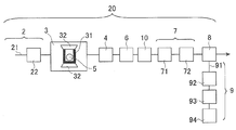
- FIG. 1 is a diagram showing an analyzer for nitrogen in a metal sample of the present invention.
- FIG. 2 is a diagram showing an analyzer for nitrogen in another metal sample of the present invention.
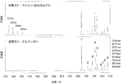
- FIG. 3 is a diagram showing emission intensity when discharging a mixed gas of argon gas and nitrogen gas and argon gas.
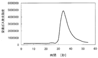
- FIG. 4 is a diagram in which the emission intensity at a wavelength of 337 nm is measured over time when a steel sample is melted in an argon stream and discharged in argon gas.
- FIG. 5 is a diagram showing uncorrected analysis values and corrected analysis values when the nitrogen analyzer of the present invention is continuously operated for a long time and a steel standard sample is analyzed at intervals of several hours.
- FIG. 6 is a diagram showing an analyzer for nitrogen in another metal sample of the present invention.
- FIG. 7 is a graph showing the relationship between the integrated value of emission intensity and the amount of nitrogen in a steel sample (Example 3).
- FIG. 1 is a diagram showing an example of an analyzer for nitrogen in a metal sample of the present invention.
- the nitrogen analyzer 1 includes an argon gas supply unit 2 and a nitrogen component contained in the metal sample 5 by melting the metal sample 5 in an atmosphere of argon gas supplied by the argon gas supply unit 2.
- an oxidizer 6 that oxidizes carbon oxide gas to water vapor and carbon dioxide
- a column unit 7 that removes water vapor and carbon dioxide from a mixed gas mainly composed of argon gas, and nitrogen-containing argon gas from which water vapor and carbon dioxide have been removed
- a discharge light emitting unit 8 that emits light by providing a light
- a photometric analysis unit 9 that measures light emitted from the discharge light emitting unit 8 to quantify nitrogen in the metal sample.
- the metal sample analyzed by the nitrogen analyzer 1 include a sample made of a titanium alloy and a sample made of steel.
- the argon gas supply unit 2 includes an argon gas supply source (not shown), an argon gas supply line 21, and a flow rate regulator 22 as a flow rate control unit provided on the argon gas supply line 21. .
- a graphite crucible 31 charged with the metal sample 5 and an electrode 32 holding the graphite crucible 31 are arranged, and the electrode 32 is connected to a power source (not shown).
- the metal sample 5 in the graphite crucible 31 is quickly moved by applying an AC current of, for example, 700 A to the electrode 32 in an atmosphere of argon gas supplied via the argon gas supply unit 2.
- the nitrogen component, hydrogen component, oxygen component and argon component contained in the metal sample 5 are vaporized to generate nitrogen gas, hydrogen gas, carbon monoxide and argon gas.
- the dust filter 4 removes the dust caused by the metal sample 5 and the graphite crucible 31 from the argon-based mixed gas (nitrogen-containing argon gas) generated in the impulse heating furnace 3 to protect the subsequent discharge light emitting unit 8. It is installed between the impulse heating furnace 3 and the oxidizer 6 as necessary.
- the dust filter 4 for example, a filter made of silica fiber or polytetrafluoroethylene and having excellent air permeability can be used.
- the oxidizer 6 is used to oxidize hydrogen gas and carbon monoxide gas generated from the metal sample 5 to water vapor and carbon dioxide gas, respectively, and is installed in the front stage of the column unit 7 as necessary.
- copper oxide or the like can be used for the oxidizer 6.
- the column unit 7 includes a de-CO 2 unit 71 and a dehydrator 72, and is used to remove carbon dioxide and water vapor in the mixed gas, respectively, and is installed in front of the discharge light emitting unit 8 as necessary.
- a de-CO 2 unit 71 sodium hydroxide can be used
- the dehydrator 72 powder such as magnesium perchlorate can be used.
- the discharge light-emitting unit 8 flows a nitrogen-containing argon gas from which carbon dioxide and water vapor have been removed between electrodes arranged at regular intervals, and loads an alternating voltage between the pair of electrodes in the nitrogen-containing argon gas. Causes a discharge.
- a material having a high light transmittance such as quartz glass can be used, and an electrolyte or a metal can be used as the electrode. That is, a known gas discharge device or silent discharge type ozone generator having such a structure can be used.
- the photometric analysis unit 9 includes an optical fiber 91 for introducing light (for example, wavelength 337 nm) emitted when the nitrogen gas excited by the discharge in the discharge light emitting unit 8 returns to the ground state to the spectroscopic unit 92, and nitrogen gas
- the spectroscopic unit 92 for extracting the emission wavelength of light and the emission wavelength of argon gas
- the photometric unit 93 for measuring the luminescence intensity divided by the spectroscopic unit 92
- the concentration of nitrogen in the steel obtained by the photometric unit 93 It is comprised from the calculating part 94 which calculates.
- the optical fiber 91 is not necessarily used between the discharge light emitting unit 8 and the spectroscopic unit 92, and the light from the discharge light emitting unit 8 can be directly guided to the spectroscopic unit 92.
- the spectroscopic unit 92 may be a spectroscopic device using an optical filter such as a bandpass filter or a diffraction grating.
- the photometry unit 93 can use a light receiving means such as a photomultiplier tube, a CCD (Charge-Coupled Device), a photodiode or the like.
- the calculation unit 94 calculates the nitrogen concentration in the metal sample from the integrated value of the emission intensity obtained by the photometry unit 93 and the weight value of the sample measured in advance.
- nitrogen contained in the metal sample 5 can be quantitatively analyzed as follows.
- the metal sample 5 is put into the graphite crucible 31.
- Argon gas is continuously supplied from the argon gas supply unit 2 to the impulse heating furnace 3.
- a current is applied to the electrode 32 to melt the metal sample 5 in an argon gas atmosphere.
- a mixed gas mainly composed of argon gas containing nitrogen gas generated by melting of the metal sample 5 is sent to the dust filter 4, and the dust is removed by the dust filter 4. And removing carbon monoxide.
- an alternating voltage is applied between the pair of electrodes while flowing a nitrogen-containing argon gas from which carbon dioxide and water vapor have been removed, thereby generating a discharge in the nitrogen-containing gas.
- the light emitted from the discharge is analyzed by the photometric analysis unit 9 to determine the concentration of nitrogen in the metal sample from the amount of nitrogen gas generated by melting the metal sample 5.
- the metal sample 5 since the nitrogen gas generated by melting the metal sample 5 is transported with argon gas and nitrogen is analyzed by the discharge light emission method, the metal sample is compared with the conventional technology transported with helium gas. The influence of the argon gas generated from 5 can be ignored, and analysis can be performed at a lower cost. In addition, the concern about the stoppage of gas supply is eliminated.
- the photometric analysis unit 9 is further provided with means for measuring the emission intensity of the argon gas, and the emission intensity of the argon gas is measured, and the standard is obtained by dividing the emission intensity of the nitrogen gas by the emission intensity of the argon gas.
- the heating temperature of the metal sample containing the nitrogen component is preferably 2500 ° C. or higher.
- the analyzer of the present invention is not limited to the above example, and can be appropriately changed.
- the analyzer of the present invention can further include an infrared absorption carbon dioxide measuring device 10 subsequent to the oxidizer 6, that is, between the oxidizer 6 and the column unit 7 (FIG. 2: the present invention).
- Analyzer 20 for nitrogen in other metal samples Oxygen in the molten metal sample reacts with the graphite crucible to generate carbon monoxide gas. When this carbon monoxide is oxidized, carbon dioxide is generated. By measuring this carbon dioxide with the infrared absorption carbon dioxide measuring device 10, in addition to nitrogen, the oxygen concentration in the metal can be quantified simultaneously.
- the infrared absorption type carbon dioxide measuring device 10 a device for measuring the concentration of carbon dioxide gas based on the infrared absorption amount of carbon dioxide gas intrinsic wavelength can be used.
- a buffer 40 can be further provided between the column unit 7 and the discharge light emitting unit 8 (FIG. 6: another metal sample of the present invention). Inside nitrogen analyzer 30). When the nitrogen content of the metal sample 5 is high, the nitrogen gas in the argon gas also has a high concentration, so that the nitrogen molecule is not sufficiently excited in the discharge light emitting unit 8 and the analysis value may be low. . On the other hand, by providing the buffer 40, the argon gas containing the high-concentration nitrogen generated by the metal sample 5 is guided to the discharge light emitting unit 8 through the buffer 40.
- the buffer 40 is preferably a path switching type buffer 40 in the pipe so that it can be selected whether or not to pass through the buffer 40 according to the concentration of nitrogen gas.
- the buffer 40 has a container-like structure having a sufficiently larger cross-sectional area than the piping, and the inside is filled with argon gas. When an analysis gas containing a high concentration of nitrogen gas flows into the buffer 40, the analysis gas is diluted with an internal argon gas, and the concentration of the nitrogen gas in the analysis gas flowing into the discharge light emitting unit 8 is reduced.
- FIG. 3 is a diagram showing the light emission intensity when light is measured by the photometric analysis unit 9 when the gas is discharged by flowing a mixed gas of argon gas and nitrogen gas or argon gas through the discharge light emitting unit 8. From FIG. 3, 337 nm, 357 nm, 380 nm, and 406 nm are observed as emission wavelengths of nitrogen gas, and 697 nm, 727 nm, 751 nm, 764 nm, 772 nm, 795 nm, 801 nm, 812 nm, and 826 nm are observed as emission wavelengths of argon gas, respectively.
- FIG. 3 337 nm, 357 nm, 380 nm, and 406 nm are observed as emission wavelengths of nitrogen gas, and 697 nm, 727 nm, 751 nm, 764 nm, 772 nm, 795 nm, 801 nm, 812 nm, and 826
- FIG. 4 is a diagram in which the emission intensity at an emission wavelength of 337 nm when a steel sample is melted in an argon stream and discharged in an argon gas is measured over time.
- the emission intensity at 337 nm changes with time, sufficient nitrogen detection sensitivity can be obtained by reading the integrated value for a certain period of time (for example, 20 seconds from 30 to 50 seconds from the start of measurement).
- any one of 337 nm, 357 nm, 380 nm, and 406 nm is measured as the emission wavelength of nitrogen gas, and the integrated value for a certain period of time is read with a calibration curve and converted into a nitrogen amount. By dividing, the nitrogen concentration in the steel sample can be obtained.
- any one of 697 nm, 727 nm, 751 nm, 764 nm, 772 nm, 795 nm, 801 nm, and 812 nm is measured as the emission wavelength of the argon gas, and an integrated value for a certain time is obtained in the same manner as in the case of the nitrogen gas.
- the discharge luminescence method is used as a method for analyzing nitrogen gas in argon gas.
- nitrogen gas generated from a metal sample melted in argon gas can be measured with high sensitivity without being affected by argon present in the metal sample.
- a hydrogen analyzer normally installed in an ironworks analysis room can be used as a device having both the argon gas supply unit 2 and the impulse heating furnace 3. Desired nitrogen can be analyzed by connecting the discharge light emission unit 8, the photometric analysis unit 9, and, if necessary, the buffer 40 to the exhaust gas portion of the hydrogen analyzer.
- the heating temperature of the impulse heating furnace needs to be 2500 ° C. or higher. This is because nitrogen in the steel does not vaporize at the standard heating temperature (about 2000 ° C.) for hydrogen analysis in steel. By using 2500 degreeC or more, when utilizing the hydrogen analyzer in steel, the problem that nitrogen in steel does not vaporize is solved.
- hydrogen and nitrogen in steel can be measured simultaneously in one sample by using a two-stage heating method such as 2000 ° C. and 3000 ° C.
- a metal sample is collected at an appropriately selected time point (such as immediately before the treatment for adjusting the nitrogen concentration) in the steelmaking process (refining process).
- the nitrogen concentration of the collected sample is analyzed using the method for analyzing nitrogen in the metal sample of the present invention.
- the conditions for the steelmaking process, particularly the treatment for adjusting the nitrogen concentration in the steel are determined, and the nitrogen concentration in the molten steel in the steelmaking process is adjusted.
- the method for adjusting the nitrogen concentration in the molten steel is not particularly limited. For example, it can be performed by using a vacuum degassing facility such as an RH vacuum degassing apparatus (RH vacuum degasser). As a result, the nitrogen concentration in the steel product can be reliably set to the target value.
- steel can be manufactured by continuously casting the molten steel whose nitrogen concentration is adjusted by the method for adjusting the nitrogen concentration in the molten steel of the present invention.
- the hot metal discharged from the blast furnace is charged into the converter through a hot metal preliminary process as necessary.
- secondary refining is performed on the molten steel produced from the converter.
- the nitrogen concentration in the molten steel is adjusted using the method for adjusting the nitrogen concentration in the molten steel of the present invention.
- continuous casting is performed to produce steel.
- the impulse heating furnace 3, the dust filter 4, the oxidizer 6 and the column unit 7 were configured by using only necessary portions from a nitrogen / oxygen analyzer EMGA-2200 (manufactured by Horiba, Ltd.).
- EMGA-2200 manufactured by Horiba, Ltd.
- an ozone generator ED-OG-R6 manufactured by Ecodesign Co., Ltd.
- the photometric analysis unit 9 was used with an ICCD (Intensified CCD) detector DH-520 (manufactured by Andor Technology) attached to an imaging spectrometer iHR320 (manufactured by Horiba, Ltd.).
- the measurement wavelength of nitrogen gas used in the photometric analysis unit was 337 nm, and the nitrogen concentration in the sample was determined from the integrated value of the emission intensity at the wavelength.
- Test Example 2 (Comparative Example 1)
- the same 13 samples as in Test Example 1 were measured by the method of Appendix 2 of JIS G1228 (2006) (ammonia distillation separation bispyrazolone absorption photometry). The highest purity products were used for hydrochloric acid, sulfuric acid, sodium hydroxide and other reagents used. Each sample was weighed to 4 g, dissolved in hydrochloric acid and then subjected to a predetermined operation. The absorbance was measured with a spectrophotometer 100-20 (manufactured by Hitachi, Ltd.), and nitrogen in the sample was measured.
- Example 3 (Comparative Example 2)
- Ten actual samples as in Example 1 were measured by the method of Annex 5 of JIS G1228 (2006) (inert gas melting-thermal conductivity method).
- the sample weighed 1 g
- the carrier gas was helium gas
- a nitrogen / oxygen analyzer EMGA-2200 manufactured by Horiba, Ltd.
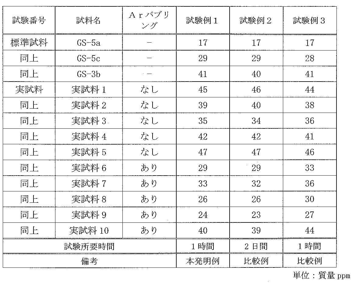
- Table 1 shows the test results.
- the cause of the positive error in the process sample of Test Example 3 is that argon gas bubbles having a thermal conductivity larger than that of nitrogen gas are present in the sample, so that the argon gas sensitizes the signal value in the thermal conductivity detector. This is because.
- test example 2 which is a wet analysis method and the test example 1 of the present invention are not affected by the argon gas, the analysis results of nitrogen coincided. That is, it can be seen that this analysis method is an effective analysis method even for a metal sample containing argon gas as bubbles. However, when the test times are compared, in this analysis method, the analysis time per sample is several minutes, and the total is about 1 hour. However, in Test Example 2, which is a wet analysis method, the results are found through a number of work steps. So it took 2 days. From the above, it was shown that the method of the present invention is a method for accurately and quickly giving the nitrogen concentration in the metal.
- Steel standard sample GS-3b (nitrogen concentration 41 ppm) was repeatedly measured under the same apparatus configuration and the same conditions as in Test Example 1. The measurement was repeated twice at a time to obtain the average analytical value, and the measurement was repeated 7 times at intervals of several hours. However, argon gas was allowed to flow through the nitrogen analyzer 1 even during the analysis, and the discharge was continued in the discharge light emitting unit 8.
- the photometric analysis unit 9 measured the emission intensity of 357 nm of nitrogen gas and the emission intensity of 697 nm of argon gas, and obtained the nitrogen concentration from the integrated value of the ratio obtained by dividing the former by the latter.
- the buffer unit 40 When the nitrogen analyzer 1 shown in FIG. 6 is used and the nitrogen-containing argon gas is bypassed to the buffer unit 40 (when the buffer unit 40 is used) under the same conditions as in Test Example 1, the buffer unit 40 is not used. (When 40 is not used), the steel standard sample JSS366-7 (nitrogen concentration 6 ppm), the steel standard sample GS-5a (17 ppm), the steel standard sample GS-3c (32 ppm), the steel standard sample GS- 2c (145 ppm) was analyzed. A blank test was also conducted. The sample weight was 1 g excluding GS-2c, and GS-2c was 0.5 g and 1 g.
- FIG. 7 shows the relationship between the integrated value of the obtained emission intensity and the nitrogen amount in the steel sample. From FIG. 7, when the buffer part 40 is not used, the emission intensity of nitrogen is saturated in the high nitrogen region, but even when the nitrogen content is high by using the buffer part 40, the emission intensity and the nitrogen amount are Shows a highly linear correlation.
- carbon is 0.03-0.06% by mass
- silicon is 0.10% by mass or less
- manganese is 0.3-1.0% by mass
- phosphorus is 0.050% by mass or less
- sulfur is 0.00%.
- a nitrogen concentration adjustment test was performed using a molten steel containing 005% by mass or less with a target nitrogen concentration of 50 ppm by mass.
- the hot metal discharged from the blast furnace was subjected to desulfurization treatment and dephosphorization hot metal pretreatment, and the hot metal was decarburized and refined in a converter to produce molten steel.
- metallic aluminum was added to deoxidize the molten steel and metal components were added.
- the obtained molten steel was conveyed to an RH vacuum degassing apparatus and subjected to vacuum degassing refining.
- the RH vacuum degassing apparatus first, after argon gas is refluxed for a predetermined time under high vacuum conditions, an analysis sample is taken from the molten steel, and then the reflux gas is changed to a mixed gas of argon gas and nitrogen to perform nitriding treatment. gave. A sample taken from the molten steel was immediately cut and polished and subjected to nitrogen analysis. Nitrogen analysis was measured using the nitrogen analyzer shown in FIG. 1 of the present invention. The obtained nitrogen analysis value was input to the calculation formula of the RH degassing apparatus during the nitriding treatment and reflected in the nitriding treatment, and the nitriding treatment was controlled with 50 mass ppm as the target value.
- a sample is finally taken from the molten steel that has been processed, and the nitrogen concentration is measured by the method of Appendix 2 of JIS G1228 (2006) (ammonia distillation separation bispyrazolone absorption photometry) and compared with the target value. It was. The above process was performed 20 charges.
- Table 2 shows the results obtained as described above.
- the average value of the charge obtained by performing nitrogen analysis on the sample before the nitriding process in the RH degassing apparatus was 50.1 ppm by mass, which was almost the target, and the standard deviation was good.
- the average value was 47.6 mass ppm, which is lower than the target, and the variation (standard deviation) was 4.28 mass ppm which is relatively more than twice as bad. there were.
Landscapes
- Chemical & Material Sciences (AREA)
- Engineering & Computer Science (AREA)
- Health & Medical Sciences (AREA)
- Mechanical Engineering (AREA)
- Life Sciences & Earth Sciences (AREA)
- Physics & Mathematics (AREA)
- Pathology (AREA)
- General Health & Medical Sciences (AREA)
- General Physics & Mathematics (AREA)
- Immunology (AREA)
- Biochemistry (AREA)
- Analytical Chemistry (AREA)
- Metallurgy (AREA)
- Materials Engineering (AREA)
- Organic Chemistry (AREA)
- Nuclear Medicine, Radiotherapy & Molecular Imaging (AREA)
- Medicinal Chemistry (AREA)
- Food Science & Technology (AREA)
- Plasma & Fusion (AREA)
- Combustion & Propulsion (AREA)
- Investigating, Analyzing Materials By Fluorescence Or Luminescence (AREA)
- Investigating And Analyzing Materials By Characteristic Methods (AREA)
Abstract
Description
本発明は上記知見に基づくものであり、特徴は以下の通りである。
[1]窒素成分を含有する金属試料をアルゴンガス雰囲気下でインパルス加熱により溶融させ、前記窒素成分を気化させる溶融工程と、前記溶融工程より生成する窒素ガスおよび前記アルゴンガスを気体放電発光法により分析して前記金属試料中の窒素を定量する分析工程と、を有することを特徴とする、金属試料中の窒素の分析方法。
[2]上記[1]において、前記気体放電発光法により窒素を定量するにあたり、窒素ガスの発光波長である、337nm、357nm、380nm、406nmのいずれか1以上を計測することを特徴とする、金属試料中の窒素の分析方法。
[3]上記[1]または[2]において、前記気体放電発光法により窒素を定量するにあたり、窒素ガスの発光強度を、同時またはアルゴンガスのみを通気している窒素ガスの非測定時に測定したアルゴンガスの発光強度で補正することを特徴とする、金属試料中の窒素の分析方法。
[4]上記[3]において、前記気体放電発光法により窒素を定量するにあたり、アルゴンガスの発光波長が697nm、727nm、751nm、764nm、772nm、795nm、801nm、812nm、826nmのいずれか1以上を計測することを特徴とする、金属試料中の窒素の分析方法。
[5]窒素成分を含有する金属試料を、アルゴンガス雰囲気下で溶融させて、前記窒素成分を気化させるインパルス加熱炉と、前記インパルス加熱炉にアルゴンガスを供給するアルゴンガス供給部と、前記インパルス加熱炉で生成した窒素ガスおよび前記インパルス加熱炉内のアルゴンガスを気体放電発光法により発光させる放電発光部と、前記放電発光部からの発光強度を測定して金属試料中の窒素を定量する測光分析部を備えることを特徴とする、金属試料中の窒素の分析装置。
[6]上記[5]において、前記測光分析部が、前記アルゴンの発光強度を計測する手段を更に備えることを特徴とする、金属試料中の窒素の分析装置。
[7]上記[5]または[6]において、前記インパルス加熱炉と前記放電発光部の間に、二酸化炭素を測定するための赤外線吸収式二酸化炭素測定装置をさらに備えることを特徴とする、金属試料中の窒素の分析装置。
[8]上記[5]~[7]のいずれかにおいて、前記インパルス加熱炉と前記放電発光部の間に、アルゴンガスの窒素成分を希釈するためのバッファ部をさらに備えることを特徴とする、金属試料中の窒素の分析装置。
[9]上記[1]~[4]のいずれかにおいて、前記インパルス加熱により窒素成分を気化させるにあたり、前記窒素成分を含有する金属試料の加熱温度を2500℃以上とすることを特徴とする、金属試料中の窒素の分析方法。
[10]溶鋼中の窒素濃度を調整する方法において、溶鋼から試料を採取し、採取した該試料の窒素濃度を、上記[1]~[4]、[9]のいずれかに記載の金属試料中の窒素の分析方法を用いて分析し、該分析により得られた窒素分析値に基づいて、窒素濃度を調整する処理の条件を決定することを特徴とする溶鋼中の窒素濃度調整方法。
[11]上記[10]に記載の溶鋼中の窒素濃度調整方法により窒素濃度が調整された溶鋼に対して、連続鋳造を行い鋼を製造することを特徴とする鋼の製造方法。
(試験例1(本発明例))
図1に示す窒素分析装置1を用いて、鉄鋼標準試料を3試料、実試料を10試料分析した。実試料10試料のうちの半分は溶鋼にアルゴンガスをバブリングして凝固させた鋼塊から採取した試料であり、残りの半分はバブリングしないで凝固させた鋼塊から採取したものである。サンプル重量は約1gとした。なお、アルゴンガス供給部2は、市販の高純度アルゴンガスボンベに流量調節器をとりつけて準備した。インパルス加熱炉3、ダストフィルタ4、酸化器6およびカラム部7は、窒素・酸素分析装置EMGA-2200(株式会社堀場製作所製)より、必要部分だけを使用することで構成した。放電発光部8はオゾン発生器 ED-OG-R6(エコデザイン株式会社製)を用いた。測光分析部9は、イメージングスペクトロメータiHR320(株式会社堀場製作所製)にICCD(Intensified CCD)検出器DH-520(アンドールテクノロジー製)を取り付けて使用した。測光分析部で用いた窒素ガスの測定波長は337nmとし、該波長の発光強度の積分値から試料中の窒素濃度を求めた。
(試験例2(比較例1))
試験例1と同じ13試料をJIS G1228(2006)の付属書2の方法(アンモニア蒸留分離ビスピラゾロン吸光光度法)で測定した。使用する塩酸、硫酸、水酸化ナトリウムおよびその他の試薬類は最高純度品を用いた。各試料のはかりとり量(weighing)は4gとし、塩酸で溶解してから所定の操作を行った後、分光光度計100-20型(日立製作所製)で吸光度を測定して、試料中の窒素濃度を求めた。
(試験例3(比較例2))
実施例1と同じ実試料10試料をJIS G1228(2006)の付属書5の方法(不活性ガス融解-熱伝導度法)で測定した。試料のはかりとり量は1g、キャリアガスはヘリウムガスとし、測定は窒素・酸素分析装置EMGA-2200(株式会社堀場製作所製)を使用した。
化学成分として、炭素が0.03~0.06質量%、珪素が0.10質量%以下、マンガンが0.3~1.0質量%、燐が0.050質量%以下、硫黄が0.005質量%以下を含有する溶鋼にて、目標窒素濃度を50質量ppmとする窒素濃度調整試験を行った。
高炉から出銑された溶銑に対して脱硫処理及び脱燐処理の溶銑予備処理を施し、この溶銑を用いて転炉にて脱炭精錬して、溶鋼を溶製した。転炉から取鍋への出鋼時、金属アルミニウムを添加して溶鋼を脱酸するとともに、金属成分を添加した。次いで、得られた溶鋼をRH真空脱ガス装置に搬送して真空脱ガス精錬を施した。RH真空脱ガス装置では、はじめに高真空条件にてアルゴンガスを所定時間還流させたのち、溶鋼から分析サンプルを採取して、次いで還流ガスをアルゴンガスと窒素の混合ガスに変えて加窒処理を施した。溶鋼から採取されたサンプルを直ちに切断研磨し、窒素分析を行った。
窒素分析は、本発明の図1に示す窒素分析装置を用いて測定した。得られた窒素分析値を、加窒処理中のRH脱ガス装置での計算式に入力し加窒処理に反映し、加窒処理は50質量ppmを目標値としてコントロールした。
RH脱ガス装置の加窒処理前に採取したサンプルをJIS G1228(2006)の付属書5の方法(不活性ガス融解-熱伝導度法)で測定した。この分析方法以外は上記本発明例と同様に行った。以上の処理を20チャージ実施した。

一方、不活性ガス融解-熱伝導度法で窒素分析した比較例では、平均値は目標より低い47.6質量ppm、ばらつき(標準偏差)も相対的に2倍以上悪い4.28質量ppmであった。これは採取した溶鋼サンプル中に直前まで還流していたアルゴンガスが偶発的に含まれていたため、不活性ガス融解-熱伝導度法の分析値が実際の窒素濃度よりも高い値となり、その後の加窒処理が不足となったことが原因と考えられる。
2 アルゴンガス供給部
3 インパルス加熱炉
4 ダストフィルタ
5 金属試料
6 酸化器
7 カラム部
8 放電発光部
9 測光分析部
10 赤外線吸収式二酸化炭素測定装置
21 アルゴンガス供給ライン
22 流量調節器
31 黒鉛るつぼ
32 電極
40 バッファ部
71 脱CO2器
72 脱水器
91 光ファイバー
92 分光部
93 測光部
94 演算部
Claims (11)
- 窒素成分を含有する金属試料をアルゴンガス雰囲気下でインパルス加熱により溶融させ、前記窒素成分を気化させる溶融工程と、
前記溶融工程より生成する窒素ガスおよび前記アルゴンガスを気体放電発光法により分析して前記金属試料中の窒素を定量する分析工程と、
を有することを特徴とする、金属試料中の窒素の分析方法。 - 前記気体放電発光法により窒素を定量するにあたり、窒素ガスの発光波長である、337nm、357nm、380nm、406nmのいずれか1以上を計測することを特徴とする、請求項1に記載の金属試料中の窒素の分析方法。
- 前記気体放電発光法により窒素を定量するにあたり、窒素ガスの発光強度を、同時またはアルゴンガスのみを通気している窒素ガスの非測定時に測定したアルゴンガスの発光強度で補正することを特徴とする、請求項1または2に記載の金属試料中の窒素の分析方法。
- 前記気体放電発光法により窒素を定量するにあたり、アルゴンガスの発光波長が697nm、727nm、751nm、764nm、772nm、795nm、801nm、812nm、826nmのいずれか1以上を計測することを特徴とする、請求項3に記載の金属試料中の窒素の分析方法。
- 窒素成分を含有する金属試料を、アルゴンガス雰囲気下で溶融させて、前記窒素成分を気化させるインパルス加熱炉と、
前記インパルス加熱炉にアルゴンガスを供給するアルゴンガス供給部と、
前記インパルス加熱炉で生成した窒素ガスおよび前記インパルス加熱炉内のアルゴンガスを気体放電発光法により発光させる放電発光部と、
前記放電発光部からの発光強度を測定して金属試料中の窒素を定量する測光分析部を備えることを特徴とする、金属試料中の窒素の分析装置。 - 前記測光分析部が、前記アルゴンの発光強度を計測する手段を更に備えることを特徴とする、請求項5に記載の金属試料中の窒素の分析装置。
- 前記インパルス加熱炉と前記放電発光部の間に、二酸化炭素を測定するための赤外線吸収式二酸化炭素測定装置をさらに備えることを特徴とする、請求項5または6に記載の金属試料中の窒素の分析装置。
- 前記インパルス加熱炉と前記放電発光部の間に、アルゴンガスの窒素成分を希釈するためのバッファ部をさらに備えることを特徴とする、請求項5~7のいずれか一項に記載の金属試料中の窒素の分析装置。
- 前記インパルス加熱により窒素成分を気化させるにあたり、前記窒素成分を含有する金属試料の加熱温度を2500℃以上とすることを特徴とする、請求項1~4のいずれか一項に記載の金属試料中の窒素の分析方法。
- 溶鋼中の窒素濃度を調整する方法において、
溶鋼から試料を採取し、
採取した該試料の窒素濃度を、請求項1~4、9のいずれか一項に記載の金属試料中の窒素の分析方法を用いて分析し、
該分析により得られた窒素分析値に基づいて、窒素濃度を調整する処理の条件を決定することを特徴とする溶鋼中の窒素濃度調整方法。 - 請求項10に記載の溶鋼中の窒素濃度調整方法により窒素濃度が調整された溶鋼に対して、連続鋳造を行い鋼を製造することを特徴とする鋼の製造方法。
Priority Applications (5)
| Application Number | Priority Date | Filing Date | Title |
|---|---|---|---|
| US15/324,176 US10641711B2 (en) | 2014-07-09 | 2015-05-14 | Method for analyzing nitrogen in metal sample, apparatus for analyzing nitrogen in metal sample, method for adjusting nitrogen concentration in molten steel, and method for manufacturing steel |
| JP2015542887A JP5846344B1 (ja) | 2014-07-09 | 2015-05-14 | 金属試料中の窒素の分析方法、金属試料中の窒素の分析装置、溶鋼中の窒素濃度調整方法および鋼の製造方法 |
| CN201580037442.6A CN106537123B (zh) | 2014-07-09 | 2015-05-14 | 金属试样中的氮的分析方法、金属试样中的氮的分析装置、钢水中的氮浓度调节方法和钢的制造方法 |
| EP15818600.7A EP3139155B1 (en) | 2014-07-09 | 2015-05-14 | Method for analyzing nitrogen in metal samples, device for analyzing nitrogen in metal samples, method for adjusting nitrogen concentration in molten steel, and steel production method |
| KR1020167034468A KR101897887B1 (ko) | 2014-07-09 | 2015-05-14 | 금속 시료 중의 질소의 분석 방법, 금속 시료 중의 질소의 분석 장치, 용강 중의 질소 농도 조정 방법 및 강의 제조 방법 |
Applications Claiming Priority (4)
| Application Number | Priority Date | Filing Date | Title |
|---|---|---|---|
| JP2014-141039 | 2014-07-09 | ||
| JP2014141039 | 2014-07-09 | ||
| JP2015-008583 | 2015-01-20 | ||
| JP2015008583 | 2015-01-20 |
Publications (1)
| Publication Number | Publication Date |
|---|---|
| WO2016006147A1 true WO2016006147A1 (ja) | 2016-01-14 |
Family
ID=55063809
Family Applications (1)
| Application Number | Title | Priority Date | Filing Date |
|---|---|---|---|
| PCT/JP2015/002447 Ceased WO2016006147A1 (ja) | 2014-07-09 | 2015-05-14 | 金属試料中の窒素の分析方法、金属試料中の窒素の分析装置、溶鋼中の窒素濃度調整方法および鋼の製造方法 |
Country Status (7)
| Country | Link |
|---|---|
| US (1) | US10641711B2 (ja) |
| EP (1) | EP3139155B1 (ja) |
| JP (1) | JP5846344B1 (ja) |
| KR (1) | KR101897887B1 (ja) |
| CN (1) | CN106537123B (ja) |
| TW (1) | TWI580946B (ja) |
| WO (1) | WO2016006147A1 (ja) |
Cited By (4)
| Publication number | Priority date | Publication date | Assignee | Title |
|---|---|---|---|---|
| JP2019074486A (ja) * | 2017-10-19 | 2019-05-16 | 大陽日酸株式会社 | 二酸化炭素ガス中の窒素ガス分析方法及び装置 |
| CN110132942A (zh) * | 2019-06-06 | 2019-08-16 | 北京科技大学 | 一种基于分析不规则试样的金属原位分析仪 |
| CN113640338A (zh) * | 2020-04-27 | 2021-11-12 | 上海梅山钢铁股份有限公司 | 一种铝质复合脱氧剂中氮含量的检测方法 |
| JP2023160452A (ja) * | 2022-04-22 | 2023-11-02 | 株式会社神戸製鋼所 | 高清浄窒素含有鋼の溶製方法、および、その溶製方法で製造された窒素含有鋼 |
Families Citing this family (6)
| Publication number | Priority date | Publication date | Assignee | Title |
|---|---|---|---|---|
| CN111289405B (zh) * | 2020-03-02 | 2022-07-01 | 哈尔滨理工大学 | 铝合金熔体氢分压惰性气体循环在线连续检测装置及其检测方法 |
| CN113447631A (zh) * | 2021-06-21 | 2021-09-28 | 西安交通大学 | 一种痕量氧分压下不锈钢氧化实验装置及实验方法 |
| CN114280100B (zh) * | 2021-12-29 | 2024-09-17 | 攀钢集团西昌钢钒有限公司 | 一种金属锰中氮含量的检测方法 |
| EP4560310A4 (en) * | 2022-07-19 | 2025-11-12 | Nippon Steel Corp | QUANTITATIVE ANALYSIS METHOD AND QUANTITATIVE ANALYSIS DEVICE |
| CN117269449A (zh) * | 2023-09-22 | 2023-12-22 | 湖南华菱涟源钢铁有限公司 | 一种螺纹钢中氮溶解度的测定方法 |
| WO2025177655A1 (ja) * | 2024-02-22 | 2025-08-28 | Jfeスチール株式会社 | 窒素濃度予測方法、窒素濃度制御方法、窒素濃度予測装置、及び窒素濃度制御装置 |
Citations (4)
| Publication number | Priority date | Publication date | Assignee | Title |
|---|---|---|---|---|
| JP2000055794A (ja) * | 1998-08-03 | 2000-02-25 | Horiba Ltd | 試料中の元素分析装置 |
| JP2000310606A (ja) * | 1999-04-27 | 2000-11-07 | Nisshin Steel Co Ltd | 不活性ガス搬送融解−熱伝導度法による鋼中の窒素の定量分析方法および分析装置 |
| JP2003139708A (ja) * | 2001-11-05 | 2003-05-14 | Kawasaki Steel Corp | 溶融金属中の成分の分析方法および分析装置 |
| JP2011099770A (ja) * | 2009-11-06 | 2011-05-19 | Taiyo Nippon Sanso Corp | アルゴンガス中の窒素濃度の測定方法 |
Family Cites Families (23)
| Publication number | Priority date | Publication date | Assignee | Title |
|---|---|---|---|---|
| FR1565337A (ja) | 1967-06-29 | 1969-05-02 | ||
| JPS613016A (ja) | 1984-06-16 | 1986-01-09 | Toyo Alum Kk | メタリツク塗膜の色調測定方法および色調測定装置 |
| JP3324186B2 (ja) | 1993-03-29 | 2002-09-17 | 株式会社島津製作所 | 発光分光分析装置 |
| CN1047444C (zh) | 1993-09-03 | 1999-12-15 | 日本贺利氏电测骑士公司 | 测定钢水中碳、氢和氮浓度的方法和装置 |
| JP3160827B2 (ja) * | 1993-09-03 | 2001-04-25 | 新日本製鐵株式会社 | 溶鋼中の炭素、水素、窒素濃度の順次連続測定方法及び装置 |
| JPH0921767A (ja) * | 1995-07-05 | 1997-01-21 | Sumitomo Metal Ind Ltd | 蛍光x線分析方法 |
| JP3083984B2 (ja) * | 1995-11-29 | 2000-09-04 | 新日本製鐵株式会社 | 鋼中成分分析用試料の加工方法 |
| JPH09152319A (ja) | 1995-11-30 | 1997-06-10 | Nippon Steel Corp | 表面品質検査方法 |
| JPH10281996A (ja) | 1997-04-09 | 1998-10-23 | Kawasaki Steel Corp | 発光分光分析方法及び装置 |
| JPH11132954A (ja) * | 1997-10-28 | 1999-05-21 | Nisshin Steel Co Ltd | 発光分光分析法による鋼中の窒素の定量分析方法 |
| JP3613016B2 (ja) | 1998-07-15 | 2005-01-26 | Jfeスチール株式会社 | 溶鋼中窒素濃度の調整方法 |
| JP4449188B2 (ja) | 2000-07-25 | 2010-04-14 | Jfeスチール株式会社 | 溶融金属中の成分の分析方法および分析装置 |
| CN1286399A (zh) | 2000-08-11 | 2001-03-07 | 钢铁研究总院 | 钢中氧化物快速测定方法 |
| JP2003310606A (ja) * | 2002-04-18 | 2003-11-05 | Ge Medical Systems Global Technology Co Llc | 超音波画像表示装置および超音波画像表示方法 |
| CN1160553C (zh) | 2002-04-19 | 2004-08-04 | 钢铁研究总院 | 金属原位统计分布分析方法 |
| US7484551B2 (en) * | 2003-10-10 | 2009-02-03 | Nucor Corporation | Casting steel strip |
| JP4844087B2 (ja) | 2005-10-31 | 2011-12-21 | Jfeスチール株式会社 | 溶鋼中の窒素濃度調整方法及び大入熱用鋼の製造方法 |
| JP4784501B2 (ja) * | 2006-12-12 | 2011-10-05 | 株式会社日立製作所 | 高圧水素流量計 |
| CN101105456B (zh) | 2007-08-13 | 2010-07-21 | 攀钢集团攀枝花钢铁研究院 | 一种合金钢样品夹杂含量快速测定的分析方法 |
| JP2011227467A (ja) * | 2010-03-31 | 2011-11-10 | Toray Ind Inc | 感光性黒色樹脂組成物、樹脂ブラックマトリクス基板 |
| KR101452233B1 (ko) | 2011-03-25 | 2014-10-22 | 도레이 카부시키가이샤 | 흑색 수지 조성물, 수지 블랙 매트릭스 기판 및 터치패널 |
| JP5836187B2 (ja) | 2012-04-20 | 2015-12-24 | 株式会社神戸製鋼所 | 真空脱ガス処理方法 |
| JP6281580B2 (ja) | 2016-01-27 | 2018-02-21 | トヨタ自動車株式会社 | 内燃機関の制御装置 |
-
2015
- 2015-05-14 KR KR1020167034468A patent/KR101897887B1/ko active Active
- 2015-05-14 US US15/324,176 patent/US10641711B2/en active Active
- 2015-05-14 JP JP2015542887A patent/JP5846344B1/ja active Active
- 2015-05-14 CN CN201580037442.6A patent/CN106537123B/zh active Active
- 2015-05-14 EP EP15818600.7A patent/EP3139155B1/en active Active
- 2015-05-14 WO PCT/JP2015/002447 patent/WO2016006147A1/ja not_active Ceased
- 2015-07-03 TW TW104121645A patent/TWI580946B/zh active
Patent Citations (4)
| Publication number | Priority date | Publication date | Assignee | Title |
|---|---|---|---|---|
| JP2000055794A (ja) * | 1998-08-03 | 2000-02-25 | Horiba Ltd | 試料中の元素分析装置 |
| JP2000310606A (ja) * | 1999-04-27 | 2000-11-07 | Nisshin Steel Co Ltd | 不活性ガス搬送融解−熱伝導度法による鋼中の窒素の定量分析方法および分析装置 |
| JP2003139708A (ja) * | 2001-11-05 | 2003-05-14 | Kawasaki Steel Corp | 溶融金属中の成分の分析方法および分析装置 |
| JP2011099770A (ja) * | 2009-11-06 | 2011-05-19 | Taiyo Nippon Sanso Corp | アルゴンガス中の窒素濃度の測定方法 |
Cited By (6)
| Publication number | Priority date | Publication date | Assignee | Title |
|---|---|---|---|---|
| JP2019074486A (ja) * | 2017-10-19 | 2019-05-16 | 大陽日酸株式会社 | 二酸化炭素ガス中の窒素ガス分析方法及び装置 |
| CN110132942A (zh) * | 2019-06-06 | 2019-08-16 | 北京科技大学 | 一种基于分析不规则试样的金属原位分析仪 |
| CN110132942B (zh) * | 2019-06-06 | 2021-01-12 | 北京科技大学 | 一种基于分析不规则试样的金属原位分析仪 |
| CN113640338A (zh) * | 2020-04-27 | 2021-11-12 | 上海梅山钢铁股份有限公司 | 一种铝质复合脱氧剂中氮含量的检测方法 |
| JP2023160452A (ja) * | 2022-04-22 | 2023-11-02 | 株式会社神戸製鋼所 | 高清浄窒素含有鋼の溶製方法、および、その溶製方法で製造された窒素含有鋼 |
| JP7739221B2 (ja) | 2022-04-22 | 2025-09-16 | 株式会社神戸製鋼所 | 高清浄窒素含有鋼の溶製方法 |
Also Published As
| Publication number | Publication date |
|---|---|
| KR101897887B1 (ko) | 2018-09-12 |
| CN106537123A (zh) | 2017-03-22 |
| KR20170007368A (ko) | 2017-01-18 |
| JP5846344B1 (ja) | 2016-01-20 |
| JPWO2016006147A1 (ja) | 2017-04-27 |
| EP3139155A4 (en) | 2017-07-05 |
| US10641711B2 (en) | 2020-05-05 |
| TW201602555A (zh) | 2016-01-16 |
| TWI580946B (zh) | 2017-05-01 |
| EP3139155A1 (en) | 2017-03-08 |
| CN106537123B (zh) | 2019-06-21 |
| US20170199129A1 (en) | 2017-07-13 |
| EP3139155B1 (en) | 2019-05-01 |
Similar Documents
| Publication | Publication Date | Title |
|---|---|---|
| JP5846344B1 (ja) | 金属試料中の窒素の分析方法、金属試料中の窒素の分析装置、溶鋼中の窒素濃度調整方法および鋼の製造方法 | |
| CN102803949B (zh) | 金属试样中的硫的分析方法和分析装置 | |
| EP0215483B1 (en) | Method of spectroscopically determining the composition of molten iron | |
| JP7832555B2 (ja) | 定量分析方法および定量分析装置 | |
| JP6447198B2 (ja) | 排ガス成分の分析装置および溶鋼の減圧脱炭処理方法 | |
| JP5896153B2 (ja) | 溶鋼の脱硫方法および製造方法 | |
| JP5684674B2 (ja) | 分析方法及び分析装置 | |
| JP5079382B2 (ja) | 溶鋼の精錬方法 | |
| JP2810790B2 (ja) | 溶融金属の直接的化学分析方法 | |
| JP4022347B2 (ja) | 分析試料中の酸素分析法 | |
| JP3439974B2 (ja) | 分析試料中の酸化物の種類別酸素又は酸化物の分析方法及び分析装置 | |
| EP2743683A1 (en) | Molten iron desulfurization method | |
| JPH10183290A (ja) | 球状黒鉛鋳鉄の材質管理方法 | |
| JP6493379B2 (ja) | 金属スラブ清浄度の評価方法および金属スラブ清浄度の評価装置 | |
| Kinoshiro et al. | New Post-combustion Ultraviolet Fluorescence Spectroscopy for Precise Determination of Trace Sulfur in Steel | |
| JP2001234230A (ja) | 脱炭精錬の終点判定方法 | |
| CN121068528A (zh) | 一种测定红外光学玻璃用高纯硒中氧含量的方法 | |
| Dorado et al. | Chemical analysis of nitrogen in steel | |
| Shyne et al. | Preparation of Spectrographic Standards of Low Boron Content for Determination of Boron in Iron | |
| CN111650295A (zh) | 一种硅粉碳含量的检测方法 | |
| JPH0221547B2 (ja) | ||
| JPH0518962A (ja) | 金属試料中の炭素および硫黄の分析方法 | |
| JPH06337245A (ja) | 発光分光分析方法 | |
| JPH02170909A (ja) | 転炉の吹止成分推定方法 |
Legal Events
| Date | Code | Title | Description |
|---|---|---|---|
| ENP | Entry into the national phase |
Ref document number: 2015542887 Country of ref document: JP Kind code of ref document: A |
|
| 121 | Ep: the epo has been informed by wipo that ep was designated in this application |
Ref document number: 15818600 Country of ref document: EP Kind code of ref document: A1 |
|
| REEP | Request for entry into the european phase |
Ref document number: 2015818600 Country of ref document: EP |
|
| WWE | Wipo information: entry into national phase |
Ref document number: 2015818600 Country of ref document: EP |
|
| ENP | Entry into the national phase |
Ref document number: 20167034468 Country of ref document: KR Kind code of ref document: A |
|
| WWE | Wipo information: entry into national phase |
Ref document number: 15324176 Country of ref document: US |
|
| NENP | Non-entry into the national phase |
Ref country code: DE |