WO2016039129A1 - 硬化した光硬化性樹脂組成物の製造方法及び装置 - Google Patents
硬化した光硬化性樹脂組成物の製造方法及び装置 Download PDFInfo
- Publication number
- WO2016039129A1 WO2016039129A1 PCT/JP2015/073832 JP2015073832W WO2016039129A1 WO 2016039129 A1 WO2016039129 A1 WO 2016039129A1 JP 2015073832 W JP2015073832 W JP 2015073832W WO 2016039129 A1 WO2016039129 A1 WO 2016039129A1
- Authority
- WO
- WIPO (PCT)
- Prior art keywords
- irradiation
- resin composition
- photocurable resin
- curing
- output
- Prior art date
- Legal status (The legal status is an assumption and is not a legal conclusion. Google has not performed a legal analysis and makes no representation as to the accuracy of the status listed.)
- Ceased
Links
Images










Classifications
-
- C—CHEMISTRY; METALLURGY
- C08—ORGANIC MACROMOLECULAR COMPOUNDS; THEIR PREPARATION OR CHEMICAL WORKING-UP; COMPOSITIONS BASED THEREON
- C08F—MACROMOLECULAR COMPOUNDS OBTAINED BY REACTIONS ONLY INVOLVING CARBON-TO-CARBON UNSATURATED BONDS
- C08F2/00—Processes of polymerisation
- C08F2/46—Polymerisation initiated by wave energy or particle radiation
-
- B—PERFORMING OPERATIONS; TRANSPORTING
- B01—PHYSICAL OR CHEMICAL PROCESSES OR APPARATUS IN GENERAL
- B01J—CHEMICAL OR PHYSICAL PROCESSES, e.g. CATALYSIS OR COLLOID CHEMISTRY; THEIR RELEVANT APPARATUS
- B01J19/00—Chemical, physical or physico-chemical processes in general; Their relevant apparatus
- B01J19/08—Processes employing the direct application of electric or wave energy, or particle radiation; Apparatus therefor
- B01J19/12—Processes employing the direct application of electric or wave energy, or particle radiation; Apparatus therefor employing electromagnetic waves
- B01J19/122—Incoherent waves
- B01J19/123—Ultraviolet light
-
- B—PERFORMING OPERATIONS; TRANSPORTING
- B01—PHYSICAL OR CHEMICAL PROCESSES OR APPARATUS IN GENERAL
- B01J—CHEMICAL OR PHYSICAL PROCESSES, e.g. CATALYSIS OR COLLOID CHEMISTRY; THEIR RELEVANT APPARATUS
- B01J19/00—Chemical, physical or physico-chemical processes in general; Their relevant apparatus
- B01J19/08—Processes employing the direct application of electric or wave energy, or particle radiation; Apparatus therefor
- B01J19/12—Processes employing the direct application of electric or wave energy, or particle radiation; Apparatus therefor employing electromagnetic waves
- B01J19/122—Incoherent waves
- B01J19/128—Infrared light
-
- B—PERFORMING OPERATIONS; TRANSPORTING
- B05—SPRAYING OR ATOMISING IN GENERAL; APPLYING FLUENT MATERIALS TO SURFACES, IN GENERAL
- B05D—PROCESSES FOR APPLYING FLUENT MATERIALS TO SURFACES, IN GENERAL
- B05D3/00—Pretreatment of surfaces to which liquids or other fluent materials are to be applied; After-treatment of applied coatings, e.g. intermediate treating of an applied coating preparatory to subsequent applications of liquids or other fluent materials
- B05D3/02—Pretreatment of surfaces to which liquids or other fluent materials are to be applied; After-treatment of applied coatings, e.g. intermediate treating of an applied coating preparatory to subsequent applications of liquids or other fluent materials by baking
- B05D3/0254—After-treatment
- B05D3/0263—After-treatment with IR heaters
-
- B—PERFORMING OPERATIONS; TRANSPORTING
- B05—SPRAYING OR ATOMISING IN GENERAL; APPLYING FLUENT MATERIALS TO SURFACES, IN GENERAL
- B05D—PROCESSES FOR APPLYING FLUENT MATERIALS TO SURFACES, IN GENERAL
- B05D3/00—Pretreatment of surfaces to which liquids or other fluent materials are to be applied; After-treatment of applied coatings, e.g. intermediate treating of an applied coating preparatory to subsequent applications of liquids or other fluent materials
- B05D3/06—Pretreatment of surfaces to which liquids or other fluent materials are to be applied; After-treatment of applied coatings, e.g. intermediate treating of an applied coating preparatory to subsequent applications of liquids or other fluent materials by exposure to radiation
- B05D3/061—Pretreatment of surfaces to which liquids or other fluent materials are to be applied; After-treatment of applied coatings, e.g. intermediate treating of an applied coating preparatory to subsequent applications of liquids or other fluent materials by exposure to radiation using U.V.
- B05D3/065—After-treatment
- B05D3/067—Curing or cross-linking the coating
-
- B—PERFORMING OPERATIONS; TRANSPORTING
- B05—SPRAYING OR ATOMISING IN GENERAL; APPLYING FLUENT MATERIALS TO SURFACES, IN GENERAL
- B05D—PROCESSES FOR APPLYING FLUENT MATERIALS TO SURFACES, IN GENERAL
- B05D7/00—Processes, other than flocking, specially adapted for applying liquids or other fluent materials to particular surfaces or for applying particular liquids or other fluent materials
- B05D7/02—Processes, other than flocking, specially adapted for applying liquids or other fluent materials to particular surfaces or for applying particular liquids or other fluent materials to macromolecular substances, e.g. rubber
- B05D7/04—Processes, other than flocking, specially adapted for applying liquids or other fluent materials to particular surfaces or for applying particular liquids or other fluent materials to macromolecular substances, e.g. rubber to surfaces of films or sheets
-
- B—PERFORMING OPERATIONS; TRANSPORTING
- B29—WORKING OF PLASTICS; WORKING OF SUBSTANCES IN A PLASTIC STATE IN GENERAL
- B29B—PREPARATION OR PRETREATMENT OF THE MATERIAL TO BE SHAPED; MAKING GRANULES OR PREFORMS; RECOVERY OF PLASTICS OR OTHER CONSTITUENTS OF WASTE MATERIAL CONTAINING PLASTICS
- B29B13/00—Conditioning or physical treatment of the material to be shaped
- B29B13/08—Conditioning or physical treatment of the material to be shaped by using wave energy or particle radiation
-
- B—PERFORMING OPERATIONS; TRANSPORTING
- B29—WORKING OF PLASTICS; WORKING OF SUBSTANCES IN A PLASTIC STATE IN GENERAL
- B29C—SHAPING OR JOINING OF PLASTICS; SHAPING OF MATERIAL IN A PLASTIC STATE, NOT OTHERWISE PROVIDED FOR; AFTER-TREATMENT OF THE SHAPED PRODUCTS, e.g. REPAIRING
- B29C35/00—Heating, cooling or curing, e.g. crosslinking or vulcanising; Apparatus therefor
- B29C35/02—Heating or curing, e.g. crosslinking or vulcanizing during moulding, e.g. in a mould
- B29C35/08—Heating or curing, e.g. crosslinking or vulcanizing during moulding, e.g. in a mould by wave energy or particle radiation
- B29C35/0805—Heating or curing, e.g. crosslinking or vulcanizing during moulding, e.g. in a mould by wave energy or particle radiation using electromagnetic radiation
-
- B—PERFORMING OPERATIONS; TRANSPORTING
- B29—WORKING OF PLASTICS; WORKING OF SUBSTANCES IN A PLASTIC STATE IN GENERAL
- B29C—SHAPING OR JOINING OF PLASTICS; SHAPING OF MATERIAL IN A PLASTIC STATE, NOT OTHERWISE PROVIDED FOR; AFTER-TREATMENT OF THE SHAPED PRODUCTS, e.g. REPAIRING
- B29C35/00—Heating, cooling or curing, e.g. crosslinking or vulcanising; Apparatus therefor
- B29C35/02—Heating or curing, e.g. crosslinking or vulcanizing during moulding, e.g. in a mould
- B29C35/08—Heating or curing, e.g. crosslinking or vulcanizing during moulding, e.g. in a mould by wave energy or particle radiation
- B29C35/10—Heating or curing, e.g. crosslinking or vulcanizing during moulding, e.g. in a mould by wave energy or particle radiation for articles of indefinite length
-
- B—PERFORMING OPERATIONS; TRANSPORTING
- B29—WORKING OF PLASTICS; WORKING OF SUBSTANCES IN A PLASTIC STATE IN GENERAL
- B29C—SHAPING OR JOINING OF PLASTICS; SHAPING OF MATERIAL IN A PLASTIC STATE, NOT OTHERWISE PROVIDED FOR; AFTER-TREATMENT OF THE SHAPED PRODUCTS, e.g. REPAIRING
- B29C71/00—After-treatment of articles without altering their shape; Apparatus therefor
- B29C71/04—After-treatment of articles without altering their shape; Apparatus therefor by wave energy or particle radiation, e.g. for curing or vulcanising preformed articles
-
- C—CHEMISTRY; METALLURGY
- C08—ORGANIC MACROMOLECULAR COMPOUNDS; THEIR PREPARATION OR CHEMICAL WORKING-UP; COMPOSITIONS BASED THEREON
- C08F—MACROMOLECULAR COMPOUNDS OBTAINED BY REACTIONS ONLY INVOLVING CARBON-TO-CARBON UNSATURATED BONDS
- C08F2/00—Processes of polymerisation
- C08F2/01—Processes of polymerisation characterised by special features of the polymerisation apparatus used
-
- C—CHEMISTRY; METALLURGY
- C08—ORGANIC MACROMOLECULAR COMPOUNDS; THEIR PREPARATION OR CHEMICAL WORKING-UP; COMPOSITIONS BASED THEREON
- C08F—MACROMOLECULAR COMPOUNDS OBTAINED BY REACTIONS ONLY INVOLVING CARBON-TO-CARBON UNSATURATED BONDS
- C08F2/00—Processes of polymerisation
- C08F2/46—Polymerisation initiated by wave energy or particle radiation
- C08F2/48—Polymerisation initiated by wave energy or particle radiation by ultraviolet or visible light
-
- C—CHEMISTRY; METALLURGY
- C08—ORGANIC MACROMOLECULAR COMPOUNDS; THEIR PREPARATION OR CHEMICAL WORKING-UP; COMPOSITIONS BASED THEREON
- C08F—MACROMOLECULAR COMPOUNDS OBTAINED BY REACTIONS ONLY INVOLVING CARBON-TO-CARBON UNSATURATED BONDS
- C08F2/00—Processes of polymerisation
- C08F2/46—Polymerisation initiated by wave energy or particle radiation
- C08F2/48—Polymerisation initiated by wave energy or particle radiation by ultraviolet or visible light
- C08F2/50—Polymerisation initiated by wave energy or particle radiation by ultraviolet or visible light with sensitising agents
-
- C—CHEMISTRY; METALLURGY
- C08—ORGANIC MACROMOLECULAR COMPOUNDS; THEIR PREPARATION OR CHEMICAL WORKING-UP; COMPOSITIONS BASED THEREON
- C08F—MACROMOLECULAR COMPOUNDS OBTAINED BY REACTIONS ONLY INVOLVING CARBON-TO-CARBON UNSATURATED BONDS
- C08F290/00—Macromolecular compounds obtained by polymerising monomers on to polymers modified by introduction of aliphatic unsaturated end or side groups
-
- C—CHEMISTRY; METALLURGY
- C08—ORGANIC MACROMOLECULAR COMPOUNDS; THEIR PREPARATION OR CHEMICAL WORKING-UP; COMPOSITIONS BASED THEREON
- C08F—MACROMOLECULAR COMPOUNDS OBTAINED BY REACTIONS ONLY INVOLVING CARBON-TO-CARBON UNSATURATED BONDS
- C08F290/00—Macromolecular compounds obtained by polymerising monomers on to polymers modified by introduction of aliphatic unsaturated end or side groups
- C08F290/02—Macromolecular compounds obtained by polymerising monomers on to polymers modified by introduction of aliphatic unsaturated end or side groups on to polymers modified by introduction of unsaturated end groups
- C08F290/06—Polymers provided for in subclass C08G
- C08F290/067—Polyurethanes; Polyureas
-
- C—CHEMISTRY; METALLURGY
- C08—ORGANIC MACROMOLECULAR COMPOUNDS; THEIR PREPARATION OR CHEMICAL WORKING-UP; COMPOSITIONS BASED THEREON
- C08G—MACROMOLECULAR COMPOUNDS OBTAINED OTHERWISE THAN BY REACTIONS ONLY INVOLVING UNSATURATED CARBON-TO-CARBON BONDS
- C08G59/00—Polycondensates containing more than one epoxy group per molecule; Macromolecules obtained by polymerising compounds containing more than one epoxy group per molecule using curing agents or catalysts which react with the epoxy groups
- C08G59/18—Macromolecules obtained by polymerising compounds containing more than one epoxy group per molecule using curing agents or catalysts which react with the epoxy groups ; e.g. general methods of curing
-
- C—CHEMISTRY; METALLURGY
- C08—ORGANIC MACROMOLECULAR COMPOUNDS; THEIR PREPARATION OR CHEMICAL WORKING-UP; COMPOSITIONS BASED THEREON
- C08G—MACROMOLECULAR COMPOUNDS OBTAINED OTHERWISE THAN BY REACTIONS ONLY INVOLVING UNSATURATED CARBON-TO-CARBON BONDS
- C08G59/00—Polycondensates containing more than one epoxy group per molecule; Macromolecules obtained by polymerising compounds containing more than one epoxy group per molecule using curing agents or catalysts which react with the epoxy groups
- C08G59/18—Macromolecules obtained by polymerising compounds containing more than one epoxy group per molecule using curing agents or catalysts which react with the epoxy groups ; e.g. general methods of curing
- C08G59/20—Macromolecules obtained by polymerising compounds containing more than one epoxy group per molecule using curing agents or catalysts which react with the epoxy groups ; e.g. general methods of curing characterised by the epoxy compounds used
- C08G59/32—Epoxy compounds containing three or more epoxy groups
- C08G59/38—Epoxy compounds containing three or more epoxy groups together with di-epoxy compounds
-
- C—CHEMISTRY; METALLURGY
- C08—ORGANIC MACROMOLECULAR COMPOUNDS; THEIR PREPARATION OR CHEMICAL WORKING-UP; COMPOSITIONS BASED THEREON
- C08G—MACROMOLECULAR COMPOUNDS OBTAINED OTHERWISE THAN BY REACTIONS ONLY INVOLVING UNSATURATED CARBON-TO-CARBON BONDS
- C08G59/00—Polycondensates containing more than one epoxy group per molecule; Macromolecules obtained by polymerising compounds containing more than one epoxy group per molecule using curing agents or catalysts which react with the epoxy groups
- C08G59/18—Macromolecules obtained by polymerising compounds containing more than one epoxy group per molecule using curing agents or catalysts which react with the epoxy groups ; e.g. general methods of curing
- C08G59/40—Macromolecules obtained by polymerising compounds containing more than one epoxy group per molecule using curing agents or catalysts which react with the epoxy groups ; e.g. general methods of curing characterised by the curing agents used
-
- B—PERFORMING OPERATIONS; TRANSPORTING
- B01—PHYSICAL OR CHEMICAL PROCESSES OR APPARATUS IN GENERAL
- B01J—CHEMICAL OR PHYSICAL PROCESSES, e.g. CATALYSIS OR COLLOID CHEMISTRY; THEIR RELEVANT APPARATUS
- B01J2219/00—Chemical, physical or physico-chemical processes in general; Their relevant apparatus
- B01J2219/08—Processes employing the direct application of electric or wave energy, or particle radiation; Apparatus therefor
- B01J2219/12—Processes employing electromagnetic waves
- B01J2219/1203—Incoherent waves
-
- B—PERFORMING OPERATIONS; TRANSPORTING
- B05—SPRAYING OR ATOMISING IN GENERAL; APPLYING FLUENT MATERIALS TO SURFACES, IN GENERAL
- B05D—PROCESSES FOR APPLYING FLUENT MATERIALS TO SURFACES, IN GENERAL
- B05D2252/00—Sheets
- B05D2252/02—Sheets of indefinite length
-
- B—PERFORMING OPERATIONS; TRANSPORTING
- B05—SPRAYING OR ATOMISING IN GENERAL; APPLYING FLUENT MATERIALS TO SURFACES, IN GENERAL
- B05D—PROCESSES FOR APPLYING FLUENT MATERIALS TO SURFACES, IN GENERAL
- B05D2502/00—Acrylic polymers
-
- B—PERFORMING OPERATIONS; TRANSPORTING
- B05—SPRAYING OR ATOMISING IN GENERAL; APPLYING FLUENT MATERIALS TO SURFACES, IN GENERAL
- B05D—PROCESSES FOR APPLYING FLUENT MATERIALS TO SURFACES, IN GENERAL
- B05D2503/00—Polyurethanes
-
- B—PERFORMING OPERATIONS; TRANSPORTING
- B05—SPRAYING OR ATOMISING IN GENERAL; APPLYING FLUENT MATERIALS TO SURFACES, IN GENERAL
- B05D—PROCESSES FOR APPLYING FLUENT MATERIALS TO SURFACES, IN GENERAL
- B05D2504/00—Epoxy polymers
-
- B—PERFORMING OPERATIONS; TRANSPORTING
- B29—WORKING OF PLASTICS; WORKING OF SUBSTANCES IN A PLASTIC STATE IN GENERAL
- B29C—SHAPING OR JOINING OF PLASTICS; SHAPING OF MATERIAL IN A PLASTIC STATE, NOT OTHERWISE PROVIDED FOR; AFTER-TREATMENT OF THE SHAPED PRODUCTS, e.g. REPAIRING
- B29C35/00—Heating, cooling or curing, e.g. crosslinking or vulcanising; Apparatus therefor
- B29C35/02—Heating or curing, e.g. crosslinking or vulcanizing during moulding, e.g. in a mould
- B29C35/08—Heating or curing, e.g. crosslinking or vulcanizing during moulding, e.g. in a mould by wave energy or particle radiation
- B29C35/0805—Heating or curing, e.g. crosslinking or vulcanizing during moulding, e.g. in a mould by wave energy or particle radiation using electromagnetic radiation
- B29C2035/0822—Heating or curing, e.g. crosslinking or vulcanizing during moulding, e.g. in a mould by wave energy or particle radiation using electromagnetic radiation using IR radiation
-
- B—PERFORMING OPERATIONS; TRANSPORTING
- B29—WORKING OF PLASTICS; WORKING OF SUBSTANCES IN A PLASTIC STATE IN GENERAL
- B29C—SHAPING OR JOINING OF PLASTICS; SHAPING OF MATERIAL IN A PLASTIC STATE, NOT OTHERWISE PROVIDED FOR; AFTER-TREATMENT OF THE SHAPED PRODUCTS, e.g. REPAIRING
- B29C35/00—Heating, cooling or curing, e.g. crosslinking or vulcanising; Apparatus therefor
- B29C35/02—Heating or curing, e.g. crosslinking or vulcanizing during moulding, e.g. in a mould
- B29C35/08—Heating or curing, e.g. crosslinking or vulcanizing during moulding, e.g. in a mould by wave energy or particle radiation
- B29C35/0805—Heating or curing, e.g. crosslinking or vulcanizing during moulding, e.g. in a mould by wave energy or particle radiation using electromagnetic radiation
- B29C2035/0827—Heating or curing, e.g. crosslinking or vulcanizing during moulding, e.g. in a mould by wave energy or particle radiation using electromagnetic radiation using UV radiation
Definitions
- the present invention relates to a method and apparatus for producing a cured photocurable resin composition, and more particularly to a technique for curing a photocurable resin composition by hybrid irradiation of infrared irradiation and ultraviolet irradiation. It is.
- a photocurable resin composition is composed mainly of (1) a monomer, (2) a prepolymer (oligomer), and (3) a photopolymerization initiator, and the monomer acts as a diluent.
- the prepolymer forms the core of the cured resin, but the monomer and prepolymer do not easily undergo a polymerization reaction by themselves, so photopolymerization
- An initiator is a component for causing such a polymerization reaction.
- Photoinitiators absorb light (especially ultraviolet light) and activate it to cause reactions such as cleavage reactions, hydrogen abstraction, and electron transfer, resulting in the formation of substances that initiate polymerization reactions such as radical molecules and hydrogen ions. Is done. These generated substances react with monomers and prepolymers to cause a three-dimensional crosslinking polymerization reaction. When molecules of a certain size or more are formed by such a polymerization reaction, the photocurable resin composition changes from a liquid state to a solid state and is cured.
- the light irradiated to activate the photopolymerization initiator is typically ultraviolet (UV), and such photocuring is also referred to as UV curing.
- the above-mentioned photocurable resin composition is used in various applications, for example, when producing a hard coat layer of a hard coat film.
- a hard coat layer When applied to a hard coat layer, there is a case where a thin film is required, and in this case, there is a problem that curling of the film occurs.
- metal oxide ultrafine particles such as colloidal silica
- the presence of the additive as described above may reduce the crosslink density and may deteriorate the hard characteristics. Therefore, there is a difficult problem that it is necessary to achieve both curl prevention and hard characteristics.
- Japanese Patent Application Laid-Open No. 8-39577 a technique for irradiating infrared rays and blowing hot air before irradiating with ultraviolet rays is described in Japanese Patent Application Laid-Open No. 8-39577.
- an ultraviolet curable aqueous solution applied to an irradiated object for example, printed matter
- infrared irradiation is performed, and then ultraviolet irradiation is performed to cure the coating film.
- 8-39953 discloses a technique in which an ultraviolet curable ink is applied to paper (printed material), and then irradiated with infrared rays and then irradiated with ultraviolet rays to cure the ink.
- a large number of ultraviolet curing lamps are required when volatile components are removed and cured simultaneously only by ultraviolet irradiation, but volatile components are removed by infrared irradiation. This is based on the principle that the curing rate can be improved without increasing the number of ultraviolet lamps by carrying out the curing by ultraviolet irradiation thereafter.
- the photopolymerization initiator is increased in order to accelerate the curing reaction by ultraviolet irradiation, but the photopolymerization initiator is relatively expensive, and thus has a problem of increasing the processing cost, and The curing reaction is accelerated to some extent under the low illuminance condition of ultraviolet irradiation, but there is also a problem that it is not so great under the high illuminance condition. Therefore, there is a demand for a technique that can perform the photocuring reaction at a lower cost and more reliably under any ultraviolet irradiation conditions.
- the present invention has been made in view of the above points, and an object of the present invention is to provide a manufacturing method and an apparatus for improving a cured photocurable resin composition by solving the drawbacks of the prior art as described above. Another object of the present invention is to provide a curing technique for a photocurable resin composition capable of significantly reducing the ultraviolet irradiation time required for the conventional photocuring reaction. Furthermore, another object of the present invention is to provide a curing technique capable of increasing the crosslink density and improving the scratch resistance to cure the photocurable resin composition. Still another object of the present invention is to provide a curing technique capable of reducing curling of a photocurable resin composition cured without using a special additive.
- the photocurable resin composition from which volatile components have been removed by heat treatment is irradiated with infrared rays (IR) at least before or after being irradiated with ultraviolet rays (UV).
- IR infrared rays
- UV ultraviolet rays
- the photocurable resin composition is irradiated with UV for a time shorter than the irradiation time necessary for the composition to reach a predetermined degree of curing only by the ultraviolet irradiation, and the degree of curing equal to or higher than the predetermined degree of curing. Is produced, and a method for producing a cured photocurable resin composition is provided.
- the predetermined degree of curing is such that the surface of the cured photocurable resin composition is not damaged when the surface is rubbed with a rubbing material under predetermined conditions.
- the rubbing material is steel wool.
- the predetermined condition is to reciprocate the rubbing substance a predetermined number of times (for example, 10) with a load of 500 g / cm 2 .
- the occurrence of the scratch is confirmed by visually and / or haze-measuring the surface after rubbing the surface.
- UV irradiation is performed within a first predetermined time after IR irradiation.
- the first predetermined time is, for example, 14 seconds.
- IR irradiation is performed within a second predetermined time after performing UV irradiation.
- the second predetermined time is, for example, one hour.
- the photocurable resin composition is a photoradical curing system or a photocationic curing system.
- the photo radical curing system is at least one of a polyester acrylate system, a urethane acrylate system, and an epoxy acrylate system.
- the post-IR irradiation is performed when the photocurable resin composition is a photocationic curing system.
- UV ultraviolet rays
- IR infrared
- the conveyance speed can be set to a speed within a range of 1 m / min to 200 m / min.
- the heating means may include at least one of at least one IR lamp, a hot air sprayer, and an electric heater.
- the UV lamp can be selected from an electrodeless lamp, a high-pressure mercury lamp, a metal halide lamp, and an LED.
- the effective irradiation dimension of the UV irradiation apparatus is such that the width perpendicular to the conveyance direction is 200 mm and the length along the conveyance direction is 200 mm.
- the vertical distance between the UV lamp and the test sample is 53 mm.
- the effective irradiation dimension of the IR irradiation apparatus is such that the width perpendicular to the conveyance direction is 200 mm and the length along the conveyance direction is 200 mm.
- the vertical distance between each IR lamp and the test sample on the transport means surface is 53 mm.
- the present invention it is possible to perform the curing process at a lower cost and faster than the prior art. Furthermore, it is possible to accelerate the cross-linking reaction and improve the scratch resistance to perform the curing treatment. Moreover, it is possible to reduce the usage-amount of the photoinitiator used in order to obtain the same degree of hardening. Furthermore, it is possible to reduce curling of the cured photocurable resin composition without using a special additive.
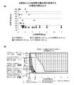
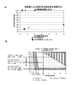
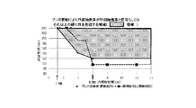
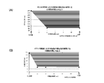
- FIG. 5 is a graph showing the relationship between the UV irradiation time and the UV output with the IR irradiation intensity as a parameter, and the test result when the polyester acrylate system is used as the photo radical curing system (Example 1).
- (B) is a region diagram in which regions for respective IR irradiation intensities are defined based on the plot diagram. Schematic of an IR / UV hybrid irradiation system used to examine the effect of scratch resistance from pre-IR irradiation as a function of time from IR irradiation to UV irradiation.
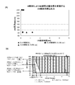
- FIG. 5 is a graph showing the relationship between the UV irradiation time and the UV output, using the IR irradiation intensity as a parameter, and the test result when the urethane acrylate system is used as the photo-radical curing system (A) is the test result.
- (B) is a region diagram in which regions for respective IR irradiation intensities are defined based on the plot diagram.
- FIG. 5 is a graph showing the relationship between the UV irradiation time and the UV output, using the IR irradiation intensity as a parameter, and the test result when the epoxy acrylate system is used as the photo radical curing system (A) is the test result.
- FIG. 3 is a graph showing the relationship between UV irradiation time and UV output, with IR irradiation intensity as a parameter, when the photopolymerization initiator Irgacure 184 used in Example 1 of FIG. 3 is replaced with lucillin TPO.
- A is a plot of test results
- B is an area diagram in which regions for each IR irradiation intensity are defined based on the plot.
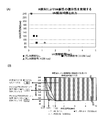
- FIG. 9 is a graph showing the relationship between the UV irradiation time and the UV output, with the IR irradiation intensity as a parameter, the test result when IR irradiation was performed after UV irradiation using the photocurable resin composition of FIG. 9 (Example 5).
- (A) is a plot of test results
- (B) is an area diagram in which regions for each IR irradiation intensity are defined based on the plot.
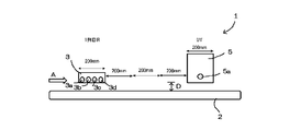
- the IR / UV hybrid irradiation system 1 having the basic configuration shown in FIG. 1 was used.
- the irradiation system 1 has an endless belt 2 having a width of 600 mm as a conveying means for conveying a test sample in the direction of arrow A.
- the transport speed of the endless belt 2 can be set to an arbitrary speed between the minimum speed (0.5 m / min) and the maximum speed (200 m / min). In this test, 1 m / min The conveying speed was set in the range of 200 m / min.
- a first-row IR irradiation device 3 is disposed above the endless belt 2 on the upstream side of the endless belt 2, and the second-row IR irradiation device 4 is positioned 200 mm away from the first-row IR irradiation device 3 on the downstream side. Is disposed, and the UV irradiation device 5 is disposed at a position further 200 mm away from the second row IR irradiation device 4 on the downstream side.
- These IR irradiation devices 3 and 4 and the UV irradiation device 5 can be disposed with their positions interchanged, and at least one of the irradiation devices can be removed. However, in the present system 1, the separation distance in the transport direction A between the pair of adjacent irradiation devices is maintained at 200 mm.
- the first-row IR irradiation device 3 has four IR lamps 3a to 3d, and these four IR lamps extend with their longitudinal axis directions orthogonal to the transport direction A. And spaced apart from each other.
- the IR irradiation device 3 has an irradiation opening whose length in the direction of the conveyance direction A is 200 mm and whose width in the direction orthogonal to the conveyance direction A is 300 mm.
- each of the IR lamps 3a to 3d is a carbon IR heater having a rated output of 1 kW (rated voltage: 230V), an output wavelength of 1 to 6 ⁇ m, and an output range of 4.2 to 33.3 W / cm. It is variable. Further, each IR lamp has a length (light emission length) of 300 mm and a diameter of 19 mm.
- the second row IR irradiation device 4 has four IR lamps 4a to 4d, and the configuration thereof is the same as that of the first row IR irradiation device 3.
- the UV irradiation device 5 has one UV lamp 5a, and the UV lamp 5a extends in the longitudinal direction perpendicular to the transport direction A.
- the UV irradiation apparatus 5 has an irradiation opening having a length in the direction of the conveyance direction A of 200 mm and a width in the direction orthogonal to the conveyance direction A of 250 mm.
- the UV lamp 5a is variable in an output wavelength range of 200 nm to 450 nm and an output range of 84 to 240 W / cm.
- the UV lamp 5a has a length (light emission length) of 250 mm and a diameter of 13 mm.
- the distance D between the test sample (not shown) conveyed on the endless belt 2 and each of the lamps 3a to 3d, 4a to 4d, and 5a is 53 mm.
- the setting of the irradiation intensity, that is, the output of each IR irradiation device 3, 4 is set by multiplying the voltage V of the power source (not shown) and the current A, while the irradiation intensity of the UV irradiation device 5, that is, the output,
- the output of the power source (not shown) is set in units of 1% in the range of 35 to 100%.
- the rated maximum output of each IR irradiation device 3, 4 used in the illustrated example is 1,000 W, and the effective irradiation width of each IR lamp is 300 mm (30 cm), so the maximum output is 33.3 W / cm.
- the minimum output that can be adjusted by a power source is 125 W
- the minimum output is 4.17 W / cm (that is, about 4.2 W / cm) divided by the effective irradiation width.
- the maximum output (100% output) of the UV irradiation apparatus 5 used in the illustrated example is 240 W / cm, and the minimum output is 35%, that is, 84 W / cm.
- Each irradiation time of IR and UV is determined from the transport speed of the endless belt 2 and the opening length in the transport direction A of each IR / UV irradiation device 3, 4 and 5. That is, in this test, since the minimum conveyance speed is 1 m / min and the maximum conveyance speed is 200 m / min, the IR irradiation time by the first row IR irradiation device 3 at the minimum conveyance speed is 200 mm / 1 m / min.
- pre-IR irradiation that is, UV irradiation is performed after performing IR irradiation on the test sample
- post IR irradiation that is, IR irradiation is performed after performing UV irradiation on the test sample
- the test sample used was a PET film used as a support and a photocurable resin composition formed on the support to a thickness of 10 ⁇ m.
- the thickness of the support used in the pre-IR irradiation mode is 100 ⁇ m
- the post-IR irradiation mode The thickness of the support used in was 50 ⁇ m.
- the size of the PET support is A4 size, and the PET support is placed on the endless belt 2 with the longitudinal direction of the PET support perpendicular to the transport direction. Therefore, IR and UV irradiation is performed with a width of 210 mm. Become.
- the test sample was prepared by applying a photocurable resin composition solution onto a PET support using a # 14 bar coater, and then oven drying at a temperature of 60 ° C. for 1 minute as a heat treatment. This was performed by removing volatile components such as a solvent from the solution. Of course, the heat treatment in this case can be performed by IR irradiation, hot air blowing, an electric heater or the like.
- the test sample used in the present verification is sufficiently coated with the photocurable resin composition solution on the PET support and then heat-treated to substantially remove volatile components such as a solvent.
- a film made of a photocurable resin composition is formed to a thickness of 10 ⁇ m on the support by drying.
- Test samples are prepared using different types of photo-curable resin compositions, and are roughly classified into photo radical curing systems and photo cation curing systems.
- the specific photocurable resin composition used in this verification is as follows.
- Photo-radical curing system (1) Polyester acrylate type 100 parts by weight of trimethylolpropane triacrylate (TMPTA: Aronix M-309 manufactured by Toagosei Co., Ltd.) as a photo-curable resin composition, 1-hydroxy-cyclohexyl-phenyl as a photopolymerization initiator -5 parts by weight of a ketone (BASF, Irgacure 184) is dissolved in 105 parts by weight of methyl ethyl ketone to prepare a 50% solid content solution.
- TMPTA trimethylolpropane triacrylate
- BASF Irgacure 184
- Urethane acrylate (urethane acrylate resin containing polyester acrylate (TMPTA) as a reactive monomer) 60 parts by weight of urethane acrylate (BASF Ralomer LR9029), 40 parts by weight of TMTPA, 5 parts by weight of Irgacure 184 as a photopolymerization initiator were dissolved in 105 parts by weight of MEK to prepare a 50% solid solution.
- TMPTA polyester acrylate
- Irgacure 184 as a photopolymerization initiator
- Epoxy acrylate epoxy acrylate resin containing polyester acrylate (TMPTA) as a reactive monomer
- An epoxy acrylate (Nagase ChemteX Denacol DA722) 60 parts by weight, TMPTA 40 parts by weight, photopolymerization initiator Irgacure 184 5 parts by weight are dissolved in MEK 105 parts by weight to prepare a 50% solid solution.
- Photocationic curing system 60 parts by weight of tetrafunctional sorbitol glycidyl ether (Denacol EX612 manufactured by Nagase ChemteX Corporation) as a photocurable resin composition, bifunctional epoxycyclohexylmethyl-epoxycyclohexanecarboxylate (alicyclic epoxy: Cyracure manufactured by Dow Chemical Co., Ltd.) UVR6110) 40 parts by weight, 8 parts by weight of 50% allylsulfonium hexafluorophosphate salt (solvent diluted product) as a photopolymerization initiator are dissolved in 104 parts by weight of methyl ethyl ketone (MEK), and a 50% solid content solution is obtained.
- MK methyl ethyl ketone
- the test sample (not shown) to be transported placed on the endless belt 2 is first subjected to IR irradiation and then to UV irradiation.
- the pre-IR irradiation mode In the system of FIG. 1, two IR irradiation devices 3 and 4 are provided, but it is needless to say that any number of IR irradiation devices can be provided.
- At least one test sample is not irradiated with IR but only irradiated with UV to cure the photocurable resin composition of the test sample. Let it be a control (UV cured sample) for comparison. Then, for at least one other test sample, IR irradiation is first performed, and then UV irradiation is performed to cure the photocurable resin composition of the test sample (IR + UV cured sample). Next, a scratch resistance test is performed on the UV cured sample and the IR + UV cured sample to compare the degree of scratching of both.
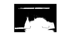
- FIG. 2 is a photograph showing one comparative example of a UV cured sample and an IR + UV cured sample subjected to a scratch resistance test.
- the UV irradiation condition for the example of FIG. 2 is that the UV output is 240 W / cm and the UV irradiation time is 1.2 seconds
- the IR irradiation condition is that the IR output is 33.3 W / cm and the IR irradiation time is 1.2.
- the elapsed time from IR irradiation to UV irradiation is 1.2 seconds.
- the left sample in FIG. 2 is a UV cured sample, and the right sample is an IR + UV cured sample. As is apparent from the photograph in FIG.
- the surface of the left UV cured sample not subjected to the pre-IR irradiation has a considerable scratch on the surface as if it was clouded by the scratch resistance test. It is understood that the surface of the right IR + UV cured sample undergoing the test is substantially free of observable scratches by a scratch resistance test.
- FIG. 3 shows the results when a polyester acrylate system is used as the photo-curable resin composition in the above-mentioned photo radical curing system.
- FIG. 3A is a plot of test results
- FIG. 3B is a region diagram created based on the plot of FIG.
- the IR output of the IR irradiation devices 3 and 4 was set to zero, 4.2 W / cm, 8.4 W / cm, 16.7 W / cm, or 33.3 W / cm. Curing treatment is performed by gradually changing the conveyance speed of the endless belt 2 on which the sample is placed from 1 m / min to 40 m / min, and gradually changing the UV irradiation time from 0.3 seconds to 12 seconds. went. Therefore, in FIG. 3A, the IR output is used as a parameter, and the result of the curing process is plotted in a graph in which the vertical axis indicates UV output (W / cm) and the horizontal axis indicates UV irradiation time (sec). FIG. 3B shows a region where the photocurable resin composition exhibits appropriate scratch resistance by UV irradiation by connecting test results for the same test conditions in the plot of FIG.
- the UV output is about 95 W / cm or more in a region that exhibits appropriate scratch resistance in the case of no pre-IR irradiation (that is, curing processing using only conventional UV irradiation).
- the UV irradiation time must be 5 seconds or more.
- the maximum value of the UV output under the test conditions is 240 W / cm.
- the UV irradiation time is 2 seconds, but as the UV output increases, the corresponding minimum UV irradiation time gradually decreases. Therefore, when a UV output exceeding 240 W / cm is used, the UV irradiation time is estimated to be shorter than 2 seconds.
- pre-IR irradiation when pre-IR irradiation is set to the minimum output of 4.2 W / cm, it is shown that the above-described UV output exhibits appropriate scratch resistance even at 84 W / cm, which is lower than 95 W / cm. In the UV output, it indicates that the UV irradiation time must be about 2.2 seconds or more. Note that 84 W / cm is only the lowest output that can be generated by the UV irradiation device 5 of the present system 1, and appropriate scratch resistance is exhibited by performing pre-IR irradiation even at a UV output lower than this. It is estimated that the minimum UV irradiation time required in that case will be longer.
- FIG. 3B it is shown that as the IR irradiation output is increased stepwise, the region where appropriate scratch resistance is obtained gradually shifts toward the shorter UV irradiation time.
- the IR output is a maximum of 33.3 W / cm
- the minimum UV irradiation time required at the minimum UV output of 84 W / cm is about 1 second
- the maximum UV irradiation output is It has been shown that the minimum UV irradiation time required at 240 W / cm is 0.3 seconds.
- the photocurable resin composition reaches a predetermined degree of cure only by UV irradiation. It is understood that a degree of cure equal to or greater than the predetermined degree of cure is generated by irradiating the photocurable resin composition with UV for a shorter UV irradiation time than necessary for UV irradiation.
- the predetermined degree of cure means that the scratch resistance of the surface of the photocurable resin composition has reached an appropriate level.
- the photocurable resin composition after the curing treatment When a surface is subjected to a scratch resistance test manually or with an abrasion tester, it can be visually confirmed that the surface is not scratched and / or desired when a haze value is measured by a haze tester. This means that a haze measurement value (%) of 1 is obtained. In addition, it is confirmed visually that the region that exhibits scratch resistance only by UV irradiation in FIG. 3B is not scratched when a test sample cured by UV irradiation alone is subjected to a scratch resistance test.
- the region that exhibits scratch resistance only by UV irradiation is the test sample when pre-IR irradiation is performed in that the surface of the test sample is not damaged by curing only with UV irradiation.
- the degree of curing is further improved.
- the photocurable resin composition can be appropriately obtained by UV irradiation over a shorter UV irradiation time that cannot be obtained by UV irradiation alone. Can be cured. That is, the curing treatment of the photocurable resin composition can be performed more rapidly, and a further improved degree of curing can be achieved.
- the second-row IR irradiating device 4 in the system 1 of FIG. 1 is maintained in a non-operating state, and the first-row IR irradiating device 3 and the UV irradiating device 5 spaced 600 mm away from the first-row IR irradiating device 3.
- the test sample was cured using only the test sample. With the IR output maintained at 33.3 W / cm and the UV output maintained at 84 W / cm, the transport speed was gradually changed to change the elapsed time from the IR irradiation device 3 to the UV irradiation device 5. Then, it was verified as to how long UV irradiation should be performed after IR irradiation. The result is shown in FIG.
- UV irradiation should be performed within 14 seconds after IR irradiation.
- the influence of the change in the level of the IR output and the UV output is negligible.
- FIG. 6 shows the results when the urethane acrylate system is used as the photo-curable resin composition in the above-mentioned photo radical curing system. Also in this case, the curing process is performed using the hybrid system of FIG. 6A is a plot of the test results, and FIG. 6B is a region diagram created based on the plot of FIG. 6A. As is apparent from the graph of FIG. 6, it is understood that this case shows the same curing tendency as in the case of Example 1 as a whole.
- the minimum and maximum values of the IR output and the UV output described above are the minimum and maximum values in the hybrid system of FIG. 1 used in this verification, and exhibit the scratch resistance by the hybrid curing process of the present invention. It should be noted that this is not the minimum and maximum values necessary for this. It is presumed that the effects of the present invention can be exhibited even in the output range exceeding the minimum and maximum values of the IR output and UV output used in this verification. This can be said not only in this embodiment but also in other embodiments.
- FIG. 7 shows the results when the epoxy acrylate system is used as the photo-curable resin composition in the above-mentioned photo radical curing system. Also in this case, the curing process is performed using the hybrid system of FIG.
- FIG. 7A is a plot of test results
- FIG. 7B is a region diagram created based on the plot of FIG. 7A. As is apparent from the graph of FIG. 7, it is understood that the same curing tendency as in Examples 1 and 2 is exhibited in this case as a whole.
- the scratch resistance is expressed even at 84 W / cm, which is the minimum output of the UV irradiation used in this verification. It is shown that the minimum value of the irradiation time is further shortened to 1.2 seconds (2 seconds in Example 2).
- the UV output is 240 W / cm or less, which is the maximum value, the minimum UV irradiation time necessary to develop the scratch resistance by performing pre-IR irradiation is compared with the case where pre-IR irradiation is not performed. It has been shown to be even shorter.
- the minimum required UV irradiation time is 0.6 seconds when the UV output is the minimum 84 W / cm. (Example 2 is 1.2 seconds), and when the UV output is the maximum 240 W / cm, the minimum necessary UV irradiation time is 0.2 seconds (0.4 Example 2). Seconds).
- the minimum UV irradiation time required to develop the scratch resistance is almost the same regardless of whether pre-IR irradiation is performed or pre-IR irradiation is performed ( About 0.2 seconds).
- Fig. 8 (A) is a plot of the test results
- Fig. 8 (B) is a graph of Fig. 8 (A). It is an area diagram created based on the plot.
- the scratch resistance is not exhibited even when the UV irradiation of 12 seconds which is the maximum UV irradiation time in the present verification is performed at the minimum output of 84 W / cm in the present verification.
- the UV irradiation of 12 seconds which is the maximum UV irradiation time in this verification the appearance of scratch resistance is observed when the UV output is 120 W / cm or more.
- the minimum necessary UV irradiation time is 4 seconds (about 2 seconds in Example 1) even at the maximum UV output (240 W / cm) in this verification.
- Example 4 the minimum UV irradiation time necessary for developing scratch resistance is significantly shortened by performing pre-IR irradiation.
- the IR output is 8.4 W / cm, which is the minimum value in this verification, it is indicated that the UV output needs to be about 95 W / cm or more in order to develop the scratch resistance.
- the UV output is about 95 W / cm
- the minimum UV irradiation time necessary for developing the scratch resistance is shortened to 2.4 seconds, while the maximum UV output is At a certain 240 W / cm, the time is shortened to 1.5 seconds.
- Example 4 the effect of shortening the minimum necessary UV irradiation time by the pre-IR irradiation based on the present invention is even greater.
- FIG. 9 shows the results when the above-described photocationic curing system is used as the photocurable resin composition.
- FIG. 9A is a plot of test results
- FIG. 9B is an area diagram created based on the plot of FIG. 9A. Also in this case, the curing process is performed using the hybrid system of FIG. As is apparent from the graph of FIG. 9, it is understood that the same curing tendency as in Example 1 is exhibited in this case as a whole.
- the minimum required UV irradiation time is 0.2 seconds when the UV output is the minimum 84 W / cm.
- the minimum necessary UV irradiation time is 0.12 seconds.
- the UV curing reaction is a three-dimensional crosslinking reaction by a photopolymerization initiator, and the crosslinking network is formed by a growth reaction from a polymerization initiation active species (polymerization initiation point) generated from the photopolymerization initiator by UV irradiation.
- a polymerization initiation active species polymerization initiation point
- the acrylic group of TMPTA undergoes addition polymerization in a chain by radicals, and the curing reaction proceeds.
- the crosslink density of the cured film depends on the number of polymerization initiation points produced by UV irradiation and the reaction rate of the acrylic group double bond of TMPTA.
- the curing reaction proceeds by ring-opening polymerization of an epoxy group.
- the scratch resistance of the cured film depends on the crosslinking density of the film surface, when the superiority of the scratch resistance is exhibited by IR irradiation before UV irradiation, the amount of polymerization initiation species by IR irradiation (that is, UV The photopolymerization initiator decomposition efficiency by irradiation) and changes in the acrylic group reaction rate should be studied.
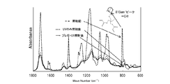
- FIG. 10 shows the change in IR absorption spectrum before and after UV irradiation, which was obtained only by (1) the spectrum before UV irradiation and (2) UV irradiation (output 240 W / cm, irradiation time 1.2 seconds).
- FIG. 11 shows the result of the conversion of acrylic double bond (reaction rate of acrylic group) obtained as a result.
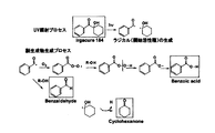
- FIG. 13 shows a cured film (dotted line in the figure) obtained by UV irradiation (output 240 W / cm, irradiation time 1.2 seconds) of TMPTA containing 5% of Irgacure 184, and the same sample before UV irradiation.
- the GC-MS measurement results are shown for a cured film (solid line in the figure) obtained by IR irradiation (output: 33.3 W / cm, irradiation time: 1.2 seconds).
- the amount of decomposition of the photopolymerization initiator depends on the amount of absorbed energy of the photopolymerization initiator, and should be constant under the same UV irradiation conditions (in this case, output 240 W / cm, 1.2 seconds)
- UV irradiation conditions in this case, output 240 W / cm, 1.2 seconds
- IR irradiation before UV irradiation reduces the amount of unreacted residual photopolymerization initiator and increases the amount of benzoic acid produced. I understand that Therefore, it is understood from this that the decomposition efficiency of the photopolymerization initiator is increased by performing IR irradiation before UV irradiation.
- a polyfunctional acrylate such as TMPTA used for a normal UV curing reaction
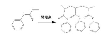
- a crosslinking reaction occurs due to UV irradiation, and the cured film becomes insoluble in a solvent, so that it becomes difficult to analyze the product by an analyzer such as a chromatogram. Therefore, when photoinitiated polymerization is performed using a monofunctional monomer such as benzyl acrylate as shown in FIG. 14, a chain polymer soluble in a solvent is obtained as the polymerization proceeds.
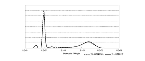
- benzyl acrylate containing 5% of Irgacure 184 was irradiated with UV, and the resulting polymer was analyzed by GPC (Gel Permeation Chromatography).
- FIG. 15 shows a chromatogram of a product obtained with a UV output of 240 W / cm and an irradiation time of 1.2 seconds.
- the IR irradiation conditions when IR irradiation was performed before UV irradiation were an output of 33.3 W / cm and an irradiation time of 2.4 seconds. From this figure, it can be seen that the peak of the produced polymer is shifted to the high molecular weight side by performing IR irradiation before UV irradiation.
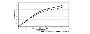
- FIG. 17 shows the results of performing UV irradiation for 0.6 seconds and 1.2 seconds, and analyzing the obtained polymer by GPC. From this result, by performing IR irradiation before UV irradiation, both the number average molecular weight and the weight average molecular weight defined by the following formulas (1) and (2) are increased as compared with the case of only UV irradiation. You can see that Usually, when the decomposition efficiency of the photopolymerization initiator is increased and the concentration of the polymerization initiation radical is increased, both the number average molecular weight and the weight average molecular weight are theoretically decreased.
- the curing reaction of the photocurable resin composition is improved by performing IR irradiation before UV irradiation. The principle was explained based on the actual measurement values. That is, first, (1) the FTIR measurement shows that the conversion rate of the acrylic group is increased with reference to FIGS. 10 and 11, and then (2) the GC is referred to with reference to FIGS.
- the MS measurement shows that the decomposition efficiency of Irgacure 184 has increased, and (3) with reference to FIGS. 14 to 16, the GPC measurement shows that the conversion rate from monomer to polymer has increased. Show.
- the measurement results by these three measurement methods all indicate that the curing reaction is improved by performing IR irradiation before UV irradiation rather than UV irradiation alone. Only Irgacure 184 is used. When quantitatively observing the photocuring reaction of the photocurable resin composition, it is important that not only the photocurable resin composition but also the photopolymerization initiator is thermally stable.
- Irgacure 127 manufactured by BASF, compound name: 2-hydroxy-1- ⁇ 4- [4- (2-hydroxy-2-methyl-propionyl) -benzyl] -phenyl ⁇ - 2-methyl-propan-1-one
- BASF compound name: 2-hydroxy-1- ⁇ 4- [4- (2-hydroxy-2-methyl-propionyl) -benzyl] -phenyl ⁇ - 2-methyl-propan-1-one
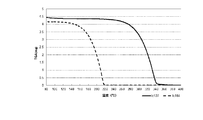
- Irgacure 127 has a higher sublimation temperature than Irgacure 184, and can therefore sublime due to heat generation during UV irradiation. As a result, it is considered that the possibility that the concentration changes even during the curing reaction by UV irradiation is lower.
- the cyclohexanedimethanol monoacrylate (manufactured by Nippon Kasei Co., Ltd.) is used for the measurement of the photolysis efficiency of Irgacure 127 by the GC-MS measurement method of (3), and Measured using methoxypolyethylene glycol (# 400) monoacrylate (AM-90G) (manufactured by Shin-Nakamura Chemical Co., Ltd.) I went again.
- test samples used in these measurements were basically prepared according to the test sample preparation method described above. That is, each test sample is obtained by applying a photocurable resin composition on a support of a PET film having an A4 size and a thickness of 100 ⁇ m. However, the thickness of the applied photocurable resin composition was 10 ⁇ m for (1) FRIT measurement and (3) GPC measurement, but was 5 ⁇ m for (2) GC-MS measurement.
- polyester acrylate M-8100 manufactured by Toa Gosei Co., Ltd.
- Irgacure 127 was formed to a thickness of 10 ⁇ m on a PET film support.
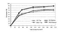
- a plurality of test samples were prepared by coating. Using these IR-UV hybrid curing systems, these test samples were output with the UV lamp while keeping the IR irradiation constant (IR output: 33 W / cm, IR irradiation time: 1.2 seconds). The UV irradiation amount of each test sample was changed to change the UV irradiation amount of each test sample, and the double bond conversion rate of the acrylic group in each case was determined.
- FIG. 19 The resulting curve showing the change in acrylic group double bond conversion rate as a function of UV irradiation energy is shown in FIG.
- “Top” like “UV-Top” and “IRUV-Top” means the surface side of the coating layer, and the surface side from the surface to the depth of 2 ⁇ m in the coating layer.
- the averaged data in the part, while “Bottom” such as “UV-Bottom” and “IRUV-Bottom” means the coating layer between the coating layer and the PET film support. It is the bottom surface side, which is data averaged in the bottom surface portion from the bottom surface to the depth of 2 ⁇ m in the coating layer.
- UV is data in the case of only UV irradiation without pre-IR irradiation
- IRUV is data in the case of performing UV irradiation after performing pre-IR irradiation.
- GC-MS Gas Chromatography Mass Spectrometry
- the substance to be inspected is made a gas and the components are separated using the chromatography method.
- GC gas chromatography
- MS mass spectrum
- a cured product cured by UV irradiation is measured by such a GC-MS method, and the decomposition efficiency (polymerization initiation active species generation efficiency) of the photopolymerization initiator is determined by performing pre-IR irradiation before UV irradiation.
- Irgacure 127 used in this verification also generates a radical by causing a cleavage reaction by UV irradiation, and the radical that did not contribute to the initiation of polymerization in the curing reaction by UV irradiation has various decompositions. It becomes a product and remains in the polymerized polymer which is a cured film.
- the degradation efficiency of Irgacure 127 which is a photopolymerization initiator, is increased by pre-IR irradiation by comparing the ratio of unreacted Irgacure 127 remaining in the cured film and the degradation living organisms. Can be determined. If the decomposition efficiency of Irgacure 127 is the same with and without pre-IR irradiation, this ratio should remain constant.
- a plurality of test samples were prepared by applying cyclohexanedimethanol monoacrylate (manufactured by Nippon Kasei Co., Ltd.) containing 50% of Irgacure 127 to a thickness of 5 ⁇ m on a PET film support.
- cyclohexanedimethanol monoacrylate is used as a support as a dissolution field for irgacure 127 to be irradiated with UV.
- these test samples were only irradiated with UV (output: 240 W / cm, irradiation time: 0.6 seconds) without pre-IR irradiation to form a coating film.
- the cured film obtained in the case of curing and pre-IR irradiation (output: 33.3 W / cm, irradiation time: 1.2 seconds), and then UV irradiation was performed under the same conditions to cure the coating film.
- GC-MS measurement was performed for each of the cured films obtained in this case.
- the respective measurement data obtained in that case are shown in FIG. 20, and the measurement data indicated by a dotted line is a case of curing only by UV irradiation without pre-IR irradiation, whereas the measurement data indicated by a solid line is This is a case where UV irradiation is performed after curing with pre-IR irradiation.
- FIG. 20 The respective measurement data obtained in that case are shown in FIG. 20, and the measurement data indicated by a dotted line is a case of curing only by UV irradiation without pre-IR irradiation, whereas the measurement data indicated by a solid line is This is a case where UV irradiation is
- the portion indicated as “unreacted initiator” indicates the unreacted residual amount of Irgacure 127, but the unreacted residual by pre-IR irradiation compared to the case of only UV irradiation. It can be seen that the amount is decreasing (ie, the solid line portion is less than the dotted line portion). Further, in FIG. 20, peaks shown as “decomposed products” are various decomposition products generated by radicals generated by the cleavage reaction of Irgacure 127 by UV irradiation. On the other hand, in FIG.
- the peak at 10 to 11 minutes on the horizontal axis is a peak derived from cyclohexanedimethanol monoacrylate and is independent of the decomposed product of Irgacure 127 and unreacted residual initiator.
- the decomposition amount of the photopolymerization initiator originally depends on the absorption energy by UV irradiation, and should be constant under the above UV irradiation conditions (output: 240 W / cm, irradiation time: 0.6 seconds).
- the measurement result of FIG. 20 shows that the amount of degrading living organisms is increased (ie, the area of the signal is increased) by performing pre-IR irradiation before UV irradiation. Yes.
- the ratio between the unreacted residual photopolymerization initiator (Irgacure 127) and various decomposition products is calculated.
- the calculation is performed for each UV irradiation condition, and the result is shown in FIG.
- the ratio between the unreacted residual photopolymerization initiator and the degrading living organisms is further increased by performing pre-IR irradiation, and the difference is further increased as the UV irradiation energy is increased. You can see that it is getting bigger. Therefore, it is understood from this result that the decomposition efficiency of the photopolymerization initiator is improved by performing pre-IR irradiation.
- a polyfunctional monomer is used in the curing reaction by UV irradiation.
- the polymer is insolubilized by a crosslinking reaction, and chromatographic analysis such as GPC becomes difficult.
- a monofunctional acrylate such as AM-90G
- a linear polymer soluble in a solvent can be obtained without proceeding with the crosslinking reaction.
- the number average molecular weight is defined by the formula (1).
- the number of polymers produced by this polymerization depends on the amount of active species for initiating photopolymerization produced by UV irradiation. That is, as the amount of the active species for initiating photopolymerization increases, the number of molecules of the generated polymer increases. In the presence of a certain amount of polymerizable acrylic monomer, theoretically, the number average molecular weight decreases as the number of molecules of the generated polymer increases. As shown in FIG.
- the number average molecular weight of the polymer obtained by UV irradiation of AM-90G decreases as the UV irradiation energy increases until reaching a certain level. Consistent with the considerations. And it is understood that the polymer (UV) obtained only by UV irradiation always has a larger number average molecular weight than the polymer (IR + UV) obtained by UV irradiation after pre-IR irradiation.
- FIG. 23 shows the change in the number average molecular weight of the polymer obtained when the UV irradiation conditions are constant (output: 240 W / cm) and the output of the pre-IR irradiation is changed. As shown in FIG. 23, it is understood that the number average molecular weight of the produced polymer gradually decreases when the output in pre-IR irradiation is increased.
- FIG. 17 is for a benzyl acrylate composition containing 5% Irgacure 184
- FIG. 22 is for AM-90G containing 2% Irgacure 127.
- Irgacure 127 has a higher sublimation temperature than Irgacure 184, it is less likely to sublimate / volatilize due to the heat generated during IR irradiation and UV irradiation. Therefore, the number average molecular weight is measured. It seems that there is an area where is reduced.
- the pre-IR irradiation is performed even if the amount of the photopolymerization initiator to be contained in the photocurable resin composition is reduced. There is a possibility that the scratch resistance equivalent to or higher than that in the case where there is not present. Therefore, in the present Example, it verified about the effect of pre IR irradiation at the time of reducing the quantity of a photoinitiator.
- the UV irradiation output needs to be 120 W / cm or more in order to develop the scratch resistance even when pre-IR irradiation is performed in the system of 2% photopolymerization initiator.
- a UV irradiation time of about 6 seconds or more is required.
- pre-IR irradiation is not performed in a system with a photopolymerization initiator of 5%, but scratch resistance is developed at about 90 W / cm or more, and at 90 W / cm, the UV irradiation time of about 6 seconds or more is also used. is necessary.
- the UV output is 120 W / cm or more
- scratch resistance is exhibited by performing pre-IR irradiation with a shorter UV irradiation time than when pre-IR irradiation is not performed.
- the minimum UV irradiation time required for developing scratch resistance by performing pre-IR irradiation is 1.2 seconds. This is significantly shorter than about 2.5 seconds when IR irradiation is not performed.
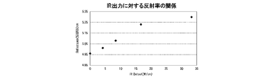
- the fact that the decomposition efficiency of the photopolymerization initiator is improved by pre-IR irradiation indicates that the crosslink density of the polymer in the cured film is increased and the density of the cured film itself is increased. Therefore, in order to verify this, the reflectance of the cured film was measured, and the result is shown in FIG. As shown in FIG. 25, it was obtained by performing only UV irradiation (output 240 W / cm, irradiation time 1.2 seconds) without pre-IR irradiation on TMPTA containing 5% Irgacure 184 as a test sample.
- the measurement result of the reflectivity of the cured film is in the range of about 4.9 to 5.1, while pre-IR irradiation (output 33.3 W / cm, irradiation time 1.2) on the test sample having the same configuration.
- the measurement result of the reflectance of the cured film obtained by performing the same UV irradiation is in the range of about 5.3 to 5.5.
- FIG. 25 it is shown that the reflectivity of the surface of the cured product is increased by performing IR irradiation for 1.2 seconds at an output of 33.3 W / cm before UV irradiation. It was found that the reflectance of the cured film can be controlled by adjusting the output of this pre-IR irradiation. That is, according to one embodiment of the present invention, it is possible to manufacture a cured film having a desired reflectance by controlling the IR dose of pre-IR irradiation.
- the UV output and irradiation time are fixed at 240 W / cm and 1.2 seconds respectively, and the pre-IR irradiation time is also fixed at 1.2 seconds.
- the surface reflectance of a cured product of TMPTA obtained when UV irradiation is carried out while changing only the output of 0 to 33.3 W / cm is shown.
- This figure shows that the surface reflectance of the cured product obtained by UV irradiation increases as a function of the output of pre-IR irradiation. Therefore, with respect to the surface reflectance, it is possible to obtain an approximate curve with the output of the pre-IR irradiation as a dependent variable, and a desired value of surface reflectivity can be obtained using the approximate curve determined in this way. It is possible to determine the power of the pre-IR irradiation to obtain.
- the cured film is simply adjusted by adjusting the pre-IR irradiation output in the production process without changing the material composition. It is possible to easily set the reflectance of the surface to a desired value.
- one viewpoint in this embodiment of post IR irradiation is whether post-curing of the photocationic curing system can be accelerated by post IR irradiation. That is, since the starting active species of the photocation curing system is an acid, the life of the curing growth process is long, and the curing reaction proceeds for a long time after UV irradiation, so that a curing period is often required. As described above, it has been found that pre-IR irradiation accelerates the curing reaction, so post-IR irradiation can also accelerate the curing reaction and reduce or eliminate the curing period that may be required after UV irradiation. There is a probability of being. Therefore, in order to verify this point, a test sample was prepared as follows.
- UV irradiation is performed, and then IR irradiation (post IR irradiation) is performed to examine the acceleration effect of the curing reaction by post IR irradiation, and the result is shown in the graph of FIG. .
- the IR irradiation output was set to 33.3 W / cm.
- the acceleration effect of the curing reaction is determined on the basis of the UV irradiation time necessary for the test sample after treatment to exhibit scratch resistance. That is, as shown in FIG. 27A, the minimum necessary UV irradiation time is 4 seconds when the UV irradiation output is 84 W / cm, and the case of FIG. 9 in which no post IR irradiation is performed.
- FIG. 27B shows the result of examining the curing reaction acceleration effect of post-IR irradiation when the IR irradiation power is changed while maintaining the state where the UV output is set to 240 W / cm which is the maximum value in this verification. It is shown in In this case as well, the determination of the curing reaction acceleration effect is based on the IR irradiation time necessary for the test sample after treatment to exhibit scratch resistance. That is, as shown in FIG. 27 (B), the minimum IR irradiation time required for exhibiting scratch resistance is 2 when the output of the post IR irradiation is 8.3 W / cm which is the lowest value in this verification. Furthermore, the minimum IR irradiation time required for exhibiting scratch resistance at the post-IR irradiation output of 33.3 W / cm, which is the maximum value in this verification, is 0.06 seconds.
- post-curing of the photocationic curing system can be accelerated by performing post IR irradiation.
- the tack free time can be shortened and the curing time can be shortened.
- a post IR process is performed when a curing period is required. It is thought that the curing period can be shortened or eliminated by this.
- the second viewpoint in the embodiment of this post IR irradiation is that the post-IR irradiation reduces the curing shrinkage stress generated by the UV curing reaction, and exhibits curl reduction and crack generation inhibiting effects. This is the point.
- the post-curing acceleration effect in the cured film can be obtained by performing the post-IR irradiation within a predetermined time after UV irradiation (1 hour in the case of a photocationic curing system). It has been found that the stress relaxation effect can be exhibited by performing post IR irradiation at an arbitrary time after UV irradiation regardless of the elapsed time from UV irradiation.
- the minimum required IR irradiation time is 24 seconds, and 33.3 W / In the case of cm, the minimum required IR irradiation time was 0.3 seconds.
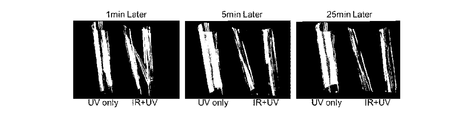
- FIG. 29 A specific example in which the stress relaxation effect (particularly, the curl reduction effect) is exhibited by post IR irradiation after UV irradiation is shown in the photograph of FIG.
- the leftmost photograph is a comparative example showing a state after 1 minute has elapsed after post-IR irradiation
- the middle photograph is a comparative example showing a state after 5 minutes has elapsed after post-IR irradiation
- the rightmost photograph is a comparative example showing a state after the lapse of 25 minutes after the post-IR irradiation
- “UV only” is a test sample which was not subjected to the post-IR irradiation only with the UV irradiation
- “IR + UV” is a test sample subjected to post IR irradiation after UV irradiation.
- the test sample used in the verification of this example uses a PET film having a film thickness of 50 ⁇ m as a support, and a 10 ⁇ m film of TMPTA containing 5% Irgacure 184 as a photocurable resin composition thereon. It is coated with a thickness.
- the UV irradiation condition is a UV output of 240 W / cm and the UV irradiation time is 1.2 seconds
- the post IR irradiation condition is an IR output of 33.3 W / cm and the IR irradiation time.
- the post-IR irradiation is performed after 2.4 seconds from the UV irradiation.
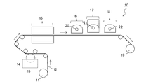
- a curing device 10 for a photocurable resin composition constructed according to one embodiment of the present invention will be described.
- a long base 12 is wound around the feed roll 11 and the base 12 is sequentially sent in the transport direction indicated by the arrows.
- a PET film as a support can be used as the substrate 12.
- the base material 12 passes through the coating zone 13, and in that case, the coating liquid 14 is applied onto the base material 12 with a predetermined film thickness.
- the coating liquid 14 can be a 50% solid content solution containing the photocurable resin composition as described above.
- the substrate 12 on which the coating liquid 14 has been applied to a predetermined film thickness is passed through a drying zone (IR lamp, hot air, electric heater, etc.) 15 to remove volatile components such as a solvent.
- a film made of a photocurable resin composition having a desired thickness by being substantially removed from the coating solution coated on 12 is formed on the substrate 12 in a sufficiently dried state.
- the base material 12 is sequentially passed through the infrared irradiation zone 16, the ultraviolet irradiation zone 17, and the infrared irradiation zone 18, and is formed on the base material 12 with a desired film thickness. Is cured.
- a predetermined number of infrared heaters 20 are disposed in the infrared irradiation zone 16, a predetermined number of ultraviolet light sources 21 are disposed in the ultraviolet irradiation zone 17, and a predetermined number of infrared heaters 22 are disposed in the infrared irradiation zone 18. Is arranged. After being cured, the substrate 12 is taken up on a take-up roll 19.
- the infrared irradiation zone 16 is provided for performing the pre-IR irradiation described above, and the infrared irradiation zone 18 is provided for performing the post-IR irradiation described above.
- both infrared irradiation zones 16 and 18 are activated, but when only one of pre-IR irradiation and post-IR irradiation is performed. Only one of the infrared irradiation zones 16 and 18 is activated.
- the IR irradiation is performed at least before and after the UV irradiation, and the unique IR exhibited by such pre-IR irradiation and post-IR irradiation. The effect will be described.
- IR / UV hybrid irradiation system 2 Endless belt 3: First row IR irradiation device 3a: IR lamp 4: Second row IR irradiation device 4a: IR lamp 5: UV irradiation device 5a: UV lamp 10: curing device 11 : Feed roll 12: Base material 13: Coating zone 14: Coating solution 15: Drying zone 16: Infrared irradiation zone 17: Ultraviolet irradiation zone 18: Infrared irradiation zone 19: Winding roll 20: Infrared heater 21: Ultraviolet light source 22 : Infrared heater
Landscapes
- Chemical & Material Sciences (AREA)
- Health & Medical Sciences (AREA)
- Chemical Kinetics & Catalysis (AREA)
- Organic Chemistry (AREA)
- Medicinal Chemistry (AREA)
- Polymers & Plastics (AREA)
- Toxicology (AREA)
- Physics & Mathematics (AREA)
- Electromagnetism (AREA)
- Engineering & Computer Science (AREA)
- General Health & Medical Sciences (AREA)
- Mechanical Engineering (AREA)
- Oral & Maxillofacial Surgery (AREA)
- Thermal Sciences (AREA)
- Life Sciences & Earth Sciences (AREA)
- Wood Science & Technology (AREA)
- Plasma & Fusion (AREA)
- Application Of Or Painting With Fluid Materials (AREA)
- Polymerisation Methods In General (AREA)
- Treatments Of Macromolecular Shaped Articles (AREA)
- Polyesters Or Polycarbonates (AREA)
- Polyurethanes Or Polyureas (AREA)
- Epoxy Resins (AREA)
- Processes Of Treating Macromolecular Substances (AREA)
- Heating, Cooling, Or Curing Plastics Or The Like In General (AREA)
Abstract
Description
光硬化性樹脂組成物を所定の経路に沿って搬送する搬送手段、
該搬送手段を任意に設定された搬送速度で駆動する駆動手段、
該光硬化性樹脂組成物から揮発成分を除去する加熱手段、
該搬送経路の上方で且つ該加熱手段の下流側に位置されており該光硬化性樹脂組成物に紫外線(UV)を照射する紫外線照射装置、
該紫外線照射装置の上流側及び下流側の少なくとも一方において該搬送経路の上方に位置されており該光硬化性樹脂組成物に赤外線(IR)を照射する赤外線照射装置、
を有している硬化装置が提供される。
(1)ポリエステルアクリレート系
光硬化性樹脂組成物としてトリメチロールプロパン・トリアクリレート(TMPTA:東亞合成製アロニックスM-309)100重量部、光重合開始剤として1-ヒドロキシ-シクロヘキシル-フェニル-ケトン(BASF社製、イルガキュア184)5重量部、をメチルエチルケトン105重量部に溶解して50%固形分溶液を調製。
ウレタンアクリレート(BASF社製ラロマーLR9029)を60重量部、TMTPAを40重量部、光重合開始剤としてイルガキュア184を5重量部、をMEK105重量部に溶解し、50%固形分溶液を調製。
エポキシアクリレート(ナガセケムテックス社製デナコールDA722)を60重量部、TMPTAを40重量部、光重合開始剤イルガキュア184を5重量部、をMEK105重量部に溶解し、50%固形分溶液を調製。
光硬化性樹脂組成物として4官能ソルビトールグリシジルエーテル(ナガセケムテックス社製デナコールEX612)60重量部、2官能エポキシシクロヘキシルメチル-エポキシシクロヘキサンカルボキシレート(脂環式エポキシ:ダウケミカル社製Cyracure UVR6110)40重量部、光重合開始剤として50%アリルスルフォニウムヘキサフルオロフォスフェート・ソルト(溶剤希釈品)8重量部、をメチルエチルケトン(MEK)104重量部に溶解し、50%固形分溶液を調製。
重量平均分子量 Mw=ΣMi2Ni/ΣMiNi (2)
尚、Mi:各分子iの分子量
Ni:分子量Miの分子iの個数
以上図10乃至17を参照して、UV照射前にIR照射を行うことによって光硬化性樹脂組成物の硬化反応が向上されていることについて実測値に基づいて原理的に説明した。即ち、先ず、(1)図10及び11を参照してFTIR測定によりアクリル基の変換率が上昇していることを示しており、次に、(2)図12及び13を参照して、GC-MS測定によりイルガキュア184の分解効率が上昇していることを示しており、更に、(3)図14乃至16を参照してGPC測定によりモノマーからポリマーへの転換率が上昇していることを示している。これら3つの測定方法による測定結果は、いずれもがUV照射のみよりもUV照射前にIR照射を行うことによって硬化反応が向上されることを示しているが、いずれの測定においても光重合開始剤としてはイルガキュア184のみを使用しているに過ぎない。光硬化性樹脂組成物の光硬化反応を定量的に観測する場合には、光硬化性樹脂組成物のみならず特に光重合開始剤が熱的に安定なものであることが重要である。何故ならば、光硬化性樹脂組成物や光重合開始剤がUV照射時に発生する熱によって昇華
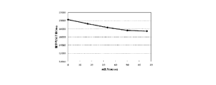
したり蒸発したりする場合には、光硬化反応の定量的な測定が不正確となる場合があるからである。例えば、別の光重合開始剤としてはイルガキュア127(BASF社製、化合物名:2-ヒドロキシ-1-{4-[4-(2-ヒドロキシ-2-メチル-プロピオニル)-ベンジル]-フェニル}-2-メチル-プロパン-1-オン)があり、イルガキュア184と比較すると昇華性が一層低いことが知られている。即ち、温度の関数としての重量減曲線特性を表している図18に示されるように、イルガキュア127はイルガキュア184と比較して昇華温度が一層高く、従って、UV照射時における発熱によっても昇華する可能性が低く、その結果、UV照射による硬化反応中においてもその濃度が変化する可能性は一層低いものと考えられる。
この場合には、5%のイルガキュア127を含むポリエステルアクリレートM-8100(東亜合成社製)をPETフィルム支持体上に10μmの厚さに塗布して複数のテストサンプルを作成した。これらのテストサンプルを、前述したIR-UVハイブリッド硬化システムを使用して、IR照射量を一定(IR出力:33W/cm、IR照射時間:1.2秒)にしたままで、UVランプの出力を変えることによって夫々のテストサンプルのUV照射量を変化させて夫々のテストサンプルをUV硬化させ、夫々の場合におけるアクリル基の二重結合コンバージョン率を決定した。その結果得られた、UV照射エネルギの関数としてのアクリル基二重結合コンバージョン率の変化を示す曲線を図19に示してある。尚、図19において、「UV-Top」及び「IRUV-Top」のように「Top」とあるのは塗布層の表面側のことであって、表面から塗布層内2μmの深さまでの表面側部分においての平均化されたデータのことであり、一方、「UV-Bottom」及び「IRUV-Bottom」のように「Bottom」とあるのは塗布層とPETフィルム支持体との間の塗布層の底面側のことであって、底面から塗布層内2μmの深さまでの底面部分において平均化されたデータのことである。更に、「UV」とはプレIR照射無しでのUV照射のみの場合のデータであって、一方「IRUV」とはプレIR照射を行った後にUV照射を行った場合のデータである。この結果から、全体的には、プレIR照射を行うことによってアクリル基の二重結合コンバージョン率が増加することが理解される。そして、プレIR照射を行った場合には、プレIR照射を行わなかった場合と比較して、同量のUV照射エネルギーに対して約10%以上の反応率が増加されていることが分かる。
GC-MS(ガスクロマトグラフィー質量分析)では、先ず、検査すべき物質を気体とさせて、クロマトグラフィー法を用いて成分分離を行う(所謂ガスクロマトグラフィー(GC))。そして、GCで分離した夫々の単一成分についてマススペクトル(MS)を測定して、分子量や開裂パターンの情報等から成分の同定を行う。この様なGC-MS法によって、UV照射によって硬化させた硬化物を測定し、光重合開始剤の分解効率(重合開始活性種生成効率)がUV照射の前にプレIR照射を行うことによってどのように変化するかを検証した。前述したイルガキュア184の場合と同様に、本検証において使用したイルガキュア127も、UV照射によって開裂反応を起こしてラジカルを生成し、UV照射による硬化反応における重合開始に寄与しなかったラジカルは種々の分解生成物となり硬化膜である重合ポリマー中に残存する。この場合に、硬化膜中に残存する未反応のイルガキュア127と分解生生物との比率を比較することによって、光重合開始剤であるイルガキュア127の分解効率がプレIR照射によって増加されるか否かを見極めることができる。もしもプレIR照射を行った場合と行わなかった場合とでイルガキュア127の分解効率が同じである場合には、この比率は一定のままであるはずである。
この場合には、2%のイルガキュア127を含むメトキシポリエチレングリコール(#400)モノアクリレート(AM-90G)(新中村化学社製)をPETフィルム支持体上に10μmの厚さに塗布して複数のテストサンプルを作成した。これらのテストサンプルを、前述したIR-UVハイブリッド硬化システムを使用して、IR照射量を一定(IR出力:33W/cm、IR照射時間:1.2秒)にしたままで、UVランプの出力を変えることによって夫々のテストサンプルのUV照射量を変化させて夫々のテストサンプルをUV硬化させ、夫々の場合に得られたポリマーの分子量をGPC(ゲル透過クロマトグラフィー)によって決定した。
溶媒履歴を短時間の高温加熱によって消去することにより、溶媒乾燥後の材料の最安定化コンフォメーションや分散微粒子の最安定分散状態を形成することができる。これにより、硬化膜の密着性、柔軟性、平滑性の向上、カールの低減、屈折率の増加等を期待することが可能となる。
コーティング/印刷時に発生する材料中の応力の履歴を消去することにより、硬化膜の密着性、柔軟性、平滑性の向上等を期待することが可能となる。
粘度低下により一層高い反応率が得られ、硬度(架橋密度)、屈折率の向上等を期待することが可能となる。又、より平滑性の高い表面状態が形成されることも期待することが可能となる。
次に、ポストIR照射により発揮される独特の効果としては以下のものがある。
UV硬化後の短時間の高温加熱により、架橋反応により生じた応力の緩和時間が短縮され、従って硬化膜の密着性、柔軟性の改善、カールの低減等を期待することが可能となる。
後硬化速度の加速により、カチオン硬化系の生産性の向上、硬化プロセスの安定性の向上等を期待することが可能となる。
UV硬化プロセスにおける問題点の一つである分解臭の低減又は除去を期待することが可能となる。
2:エンドレスベルト
3:1列目IR照射装置
3a:IRランプ
4:2列目IR照射装置
4a:IRランプ
5:UV照射装置
5a:UVランプ
10:硬化装置
11:送り出しロール
12:基材
13:塗工ゾーン
14:塗工液
15:乾燥ゾーン
16:赤外線照射ゾーン
17:紫外線照射ゾーン
18:赤外線照射ゾーン
19:巻取りロール
20:赤外線ヒーター
21:紫外線光源
22:赤外線ヒーター
Claims (16)
- 加熱処理によって揮発成分を除去した光硬化性樹脂組成物を紫外線照射する前又は後の少なくとも一方において赤外線照射を行い、該光硬化性樹脂組成物が該紫外線照射のみによって所定の硬化度に到達するのに必要な照射時間よりも短い紫外線照射時間にわたって該光硬化性樹脂組成物の紫外線照射を行って該所定の硬化度以上の硬化度を発生させる、ことを特徴とする硬化した光硬化性樹脂組成物を製造する方法。
- 該所定の硬化度とは、硬化された該光硬化性樹脂組成物の表面を所定の条件において摺擦物質で摺擦した場合に該表面において傷付きが発生しない程度の硬化度である請求項1記載の方法。
- 該摺擦物資がスチールウールである請求項2記載の方法。
- 該所定の条件が荷重500g/cm2で該摺擦物質を該表面上を所定回数往復させることを包含している請求項1又は2記載の方法。
- 紫外線照射する前に赤外線照射を行う場合には、該赤外線照射を行った後14秒以内に該紫外線照射を行う請求項1乃至4の内のいずれか1項記載の方法。
- 紫外線照射した後に赤外線照射を行う場合には、該紫外線照射を行った後1時間以内に該赤外線照射を行う請求項1乃至5の内のいずれか1項記載の方法。
- 該光硬化性樹脂組成物が光ラジカル硬化系又は光カチオン硬化系のいずれかである請求項1乃至6の内のいずれか1項記載の方法。
- 該光ラジカル硬化系が、ポリエステルアクリレート系、ウレタンアクリレート系、エポキシアクリレート系、の内の一つである請求項7記載の方法。
- 養生期間を少なくとも短縮させるか及び/又は応力緩和効果を発揮させるために、紫外線照射の後に赤外線照射を行う請求項1乃至7の内のいずれか1項記載の方法。
- 光硬化性樹脂組成物を所定の経路に沿って搬送する搬送手段、
該搬送手段を任意に設定された搬送速度で駆動する駆動手段、
該光硬化性樹脂組成物から揮発成分を除去する加熱手段、
該搬送経路の上方で且つ該加熱手段の下流側に位置されており該光硬化性樹脂組成物に紫外線を照射する紫外線照射装置、
該紫外線照射装置の上流側及び下流側の少なくとも一方において該搬送経路の上方に位置されており該光硬化性樹脂組成物に赤外線を照射する少なくとも1個の赤外線照射装置、
を有している光硬化性樹脂組成物の硬化装置。 - 加熱処理によって揮発成分を除去した光硬化性樹脂組成物に対して第1出力レベルで赤外線照射を行い、次いで、該光硬化性樹脂組成物に対して所定の出力レベルの紫外線照射を行って該光硬化性樹脂組成物を硬化させ、前記第1出力レベルに対応する値の反射率を有する硬化した光硬化性樹脂組成物を製造する方法。
- 該第1出力レベルとそれに対応する値の反射率とは、該光硬化性樹脂組成物の組成に基づいて予め決定されている請求項11記載の方法。
- 紫外線に照射させることにより硬化された光硬化性樹脂組成物において、該光硬化性樹脂組成物が該紫外線の照射によって硬化された場合に有する反射率よりも一層高い反射率を有していることを特徴とする光硬化性樹脂組成物。
- 該紫外線照射を行う前に該光硬化性樹脂組成物を赤外線に照射させることによって該一層高い反射率が得られている請求項13記載の光硬化性樹脂組成物。
- 光硬化性樹脂組成物の紫外線照射による硬化時における反射率を制御する方法において、
該光硬化性樹脂組成物に赤外線を照射し、
次いで、該光硬化性樹脂組成物に紫外線を照射して該光硬化性樹脂組成物を硬化させる、
上記各ステップを有しており、硬化された該光硬化性樹脂組成物の反射率を該赤外線の照射量によって可変的に制御する方法。 - 前記反射率は該赤外線照射を行わなかった場合と比較して該赤外線照射を該紫外線照射の前に行うことによって一層増加されている請求項15記載の方法。
Priority Applications (7)
| Application Number | Priority Date | Filing Date | Title |
|---|---|---|---|
| KR1020167015135A KR101892832B1 (ko) | 2014-09-11 | 2015-08-25 | 경화된 광경화성 수지 조성물의 제조를 위한 장치 및 방법 |
| CA2931079A CA2931079C (en) | 2014-09-11 | 2015-08-25 | Apparatus and method for manufacturing a cured photocurable resin composition |
| EP15840770.0A EP3061773B1 (en) | 2014-09-11 | 2015-08-25 | Method and device for manufacturing cured light-curing resin composition |
| JP2016547342A JP6554106B2 (ja) | 2014-09-11 | 2015-08-25 | 硬化した光硬化性樹脂組成物の製造方法及び装置 |
| US15/108,762 US9868796B2 (en) | 2014-09-11 | 2015-08-25 | Method and device for manufacturing cured light-curing resin composition |
| CN201580025851.4A CN106459243B (zh) | 2014-09-11 | 2015-08-25 | 制造固化的光固化性树脂组合物的设备和方法 |
| US15/819,839 US10273316B2 (en) | 2014-09-11 | 2017-11-21 | Method and device for manufacturing cured light-curing resin composition |
Applications Claiming Priority (2)
| Application Number | Priority Date | Filing Date | Title |
|---|---|---|---|
| JP2014185132 | 2014-09-11 | ||
| JP2014-185132 | 2014-09-11 |
Related Child Applications (2)
| Application Number | Title | Priority Date | Filing Date |
|---|---|---|---|
| US15/108,762 A-371-Of-International US9868796B2 (en) | 2014-09-11 | 2015-08-25 | Method and device for manufacturing cured light-curing resin composition |
| US15/819,839 Division US10273316B2 (en) | 2014-09-11 | 2017-11-21 | Method and device for manufacturing cured light-curing resin composition |
Publications (1)
| Publication Number | Publication Date |
|---|---|
| WO2016039129A1 true WO2016039129A1 (ja) | 2016-03-17 |
Family
ID=55458885
Family Applications (1)
| Application Number | Title | Priority Date | Filing Date |
|---|---|---|---|
| PCT/JP2015/073832 Ceased WO2016039129A1 (ja) | 2014-09-11 | 2015-08-25 | 硬化した光硬化性樹脂組成物の製造方法及び装置 |
Country Status (8)
| Country | Link |
|---|---|
| US (2) | US9868796B2 (ja) |
| EP (1) | EP3061773B1 (ja) |
| JP (1) | JP6554106B2 (ja) |
| KR (1) | KR101892832B1 (ja) |
| CN (1) | CN106459243B (ja) |
| CA (1) | CA2931079C (ja) |
| TW (1) | TWI688590B (ja) |
| WO (1) | WO2016039129A1 (ja) |
Cited By (9)
| Publication number | Priority date | Publication date | Assignee | Title |
|---|---|---|---|---|
| JP2016088980A (ja) * | 2014-10-31 | 2016-05-23 | 株式会社ダイセル | レーザー光照射による硬化物の製造方法 |
| JP2016200746A (ja) * | 2015-04-13 | 2016-12-01 | コニカミノルタ株式会社 | 電子写真感光体の製造方法 |
| WO2016208596A1 (ja) * | 2015-06-22 | 2016-12-29 | 住友化学株式会社 | 有機電子素子の製造方法及び正孔注入層の形成方法 |
| WO2016208597A1 (ja) * | 2015-06-22 | 2016-12-29 | 住友化学株式会社 | 有機電子素子の製造方法及び有機薄膜の形成方法 |
| US9868796B2 (en) | 2014-09-11 | 2018-01-16 | Heraeus Kabushiki Kaisha | Method and device for manufacturing cured light-curing resin composition |
| JP2019123821A (ja) * | 2018-01-18 | 2019-07-25 | 凸版印刷株式会社 | 樹脂成形体および樹脂成形体の製造方法 |
| JP2020007393A (ja) * | 2018-07-03 | 2020-01-16 | 凸版印刷株式会社 | 樹脂成形体および樹脂成形体の製造方法 |
| JP2020070405A (ja) * | 2018-11-02 | 2020-05-07 | 凸版印刷株式会社 | 樹脂成形体および樹脂成形体の製造方法 |
| JP2022098091A (ja) * | 2020-12-21 | 2022-07-01 | シャープ株式会社 | フィルム |
Families Citing this family (3)
| Publication number | Priority date | Publication date | Assignee | Title |
|---|---|---|---|---|
| CN110446760B (zh) | 2017-05-22 | 2021-12-24 | 乐金华奥斯株式会社 | 耐污染性优异的低光泽固化物及其制备方法 |
| JP6440802B1 (ja) * | 2017-11-08 | 2018-12-19 | 住友化学株式会社 | 有機デバイスの製造方法 |
| JP2023007731A (ja) * | 2021-07-02 | 2023-01-19 | 住友電気工業株式会社 | 光ファイバの製造方法および製造装置 |
Citations (7)
| Publication number | Priority date | Publication date | Assignee | Title |
|---|---|---|---|---|
| JPS5048092A (ja) * | 1973-08-29 | 1975-04-28 | ||
| JPS59132974A (ja) * | 1983-01-21 | 1984-07-31 | Touka Shikiso Kagaku Kogyo Kk | 紫外線硬化塗装金属板の高速硬化法 |
| JPS59168073A (ja) * | 1983-03-15 | 1984-09-21 | Mitsubishi Chem Ind Ltd | 被膜形成性組成物およびそれを用いた合成樹脂成形品の表面改良法 |
| JPS61165754A (ja) * | 1985-01-17 | 1986-07-26 | Asahi Chem Ind Co Ltd | パタ−ン形成法 |
| JPH11128826A (ja) * | 1997-10-30 | 1999-05-18 | Kansai Paint Co Ltd | コ−ティング方法 |
| JP2001170561A (ja) * | 1999-12-17 | 2001-06-26 | Toppan Forms Co Ltd | Uv硬化型感圧接着剤皮膜の硬化方法 |
| JP2004505159A (ja) * | 2000-07-31 | 2004-02-19 | ピーピージー インダストリーズ オハイオ, インコーポレイテッド | 改善された引っ掻き抵抗性を有する二重硬化コーティング組成物、コーティング基板、およびそれに関連する方法 |
Family Cites Families (11)
| Publication number | Priority date | Publication date | Assignee | Title |
|---|---|---|---|---|
| JPS5098092A (ja) | 1974-01-05 | 1975-08-04 | ||
| DE4122743C1 (ja) * | 1991-07-10 | 1992-11-26 | Fraunhofer-Gesellschaft Zur Foerderung Der Angewandten Forschung Ev, 8000 Muenchen, De | |
| JPH0839953A (ja) | 1994-07-28 | 1996-02-13 | Iwasaki Electric Co Ltd | 紫外線硬化型インキの硬化方法 |
| JPH0839577A (ja) | 1994-07-28 | 1996-02-13 | Iwasaki Electric Co Ltd | 紫外線硬化型水性樹脂用の硬化装置 |
| JPH09118706A (ja) * | 1995-10-25 | 1997-05-06 | Nippon Paint Co Ltd | 光重合性組成物の硬化方法 |
| US5922783A (en) * | 1997-02-27 | 1999-07-13 | Loctite Corporation | Radiation-curable, cyanoacrylate-containing compositions |
| JP4552480B2 (ja) | 2004-03-31 | 2010-09-29 | 日本製紙株式会社 | ハードコートフィルム及びその製造方法 |
| US8956457B2 (en) * | 2006-09-08 | 2015-02-17 | Tokyo Electron Limited | Thermal processing system for curing dielectric films |
| US20100183820A1 (en) * | 2009-01-16 | 2010-07-22 | Ford Global Technologies, Llc | Methods for curing uv-curable coatings |
| JP5048092B2 (ja) * | 2010-02-16 | 2012-10-17 | 東芝テック株式会社 | アンテナおよび携帯機器 |
| KR101892832B1 (ko) | 2014-09-11 | 2018-08-28 | 헤라우스 가부시키 가이샤 | 경화된 광경화성 수지 조성물의 제조를 위한 장치 및 방법 |
-
2015
- 2015-08-25 KR KR1020167015135A patent/KR101892832B1/ko active Active
- 2015-08-25 CA CA2931079A patent/CA2931079C/en active Active
- 2015-08-25 CN CN201580025851.4A patent/CN106459243B/zh active Active
- 2015-08-25 US US15/108,762 patent/US9868796B2/en active Active
- 2015-08-25 EP EP15840770.0A patent/EP3061773B1/en active Active
- 2015-08-25 JP JP2016547342A patent/JP6554106B2/ja active Active
- 2015-08-25 WO PCT/JP2015/073832 patent/WO2016039129A1/ja not_active Ceased
- 2015-09-11 TW TW104130085A patent/TWI688590B/zh active
-
2017
- 2017-11-21 US US15/819,839 patent/US10273316B2/en active Active
Patent Citations (7)
| Publication number | Priority date | Publication date | Assignee | Title |
|---|---|---|---|---|
| JPS5048092A (ja) * | 1973-08-29 | 1975-04-28 | ||
| JPS59132974A (ja) * | 1983-01-21 | 1984-07-31 | Touka Shikiso Kagaku Kogyo Kk | 紫外線硬化塗装金属板の高速硬化法 |
| JPS59168073A (ja) * | 1983-03-15 | 1984-09-21 | Mitsubishi Chem Ind Ltd | 被膜形成性組成物およびそれを用いた合成樹脂成形品の表面改良法 |
| JPS61165754A (ja) * | 1985-01-17 | 1986-07-26 | Asahi Chem Ind Co Ltd | パタ−ン形成法 |
| JPH11128826A (ja) * | 1997-10-30 | 1999-05-18 | Kansai Paint Co Ltd | コ−ティング方法 |
| JP2001170561A (ja) * | 1999-12-17 | 2001-06-26 | Toppan Forms Co Ltd | Uv硬化型感圧接着剤皮膜の硬化方法 |
| JP2004505159A (ja) * | 2000-07-31 | 2004-02-19 | ピーピージー インダストリーズ オハイオ, インコーポレイテッド | 改善された引っ掻き抵抗性を有する二重硬化コーティング組成物、コーティング基板、およびそれに関連する方法 |
Non-Patent Citations (1)
| Title |
|---|
| See also references of EP3061773A4 * |
Cited By (17)
| Publication number | Priority date | Publication date | Assignee | Title |
|---|---|---|---|---|
| US9868796B2 (en) | 2014-09-11 | 2018-01-16 | Heraeus Kabushiki Kaisha | Method and device for manufacturing cured light-curing resin composition |
| US10273316B2 (en) | 2014-09-11 | 2019-04-30 | Heraeus Kabushiki Kaisha | Method and device for manufacturing cured light-curing resin composition |
| JP2016088980A (ja) * | 2014-10-31 | 2016-05-23 | 株式会社ダイセル | レーザー光照射による硬化物の製造方法 |
| JP2016200746A (ja) * | 2015-04-13 | 2016-12-01 | コニカミノルタ株式会社 | 電子写真感光体の製造方法 |
| US10333067B2 (en) | 2015-06-22 | 2019-06-25 | Sumitomo Chemical Company, Limited | Method for manufacturing organic electronic element, and method for forming electron hole injection layer |
| JPWO2016208597A1 (ja) * | 2015-06-22 | 2018-04-05 | 住友化学株式会社 | 有機電子素子の製造方法及び有機薄膜の形成方法 |
| JPWO2016208596A1 (ja) * | 2015-06-22 | 2018-04-05 | 住友化学株式会社 | 有機電子素子の製造方法及び正孔注入層の形成方法 |
| WO2016208597A1 (ja) * | 2015-06-22 | 2016-12-29 | 住友化学株式会社 | 有機電子素子の製造方法及び有機薄膜の形成方法 |
| WO2016208596A1 (ja) * | 2015-06-22 | 2016-12-29 | 住友化学株式会社 | 有機電子素子の製造方法及び正孔注入層の形成方法 |
| JP2019123821A (ja) * | 2018-01-18 | 2019-07-25 | 凸版印刷株式会社 | 樹脂成形体および樹脂成形体の製造方法 |
| JP7298112B2 (ja) | 2018-01-18 | 2023-06-27 | 凸版印刷株式会社 | 樹脂成形体および樹脂成形体の製造方法 |
| JP2020007393A (ja) * | 2018-07-03 | 2020-01-16 | 凸版印刷株式会社 | 樹脂成形体および樹脂成形体の製造方法 |
| JP2020070405A (ja) * | 2018-11-02 | 2020-05-07 | 凸版印刷株式会社 | 樹脂成形体および樹脂成形体の製造方法 |
| JP7275533B2 (ja) | 2018-11-02 | 2023-05-18 | 凸版印刷株式会社 | 樹脂成形体の製造方法 |
| JP2022098091A (ja) * | 2020-12-21 | 2022-07-01 | シャープ株式会社 | フィルム |
| JP7549519B2 (ja) | 2020-12-21 | 2024-09-11 | シャープ株式会社 | フィルム |
| US12331184B2 (en) | 2020-12-21 | 2025-06-17 | Sharp Kabushiki Kaisha | Film |
Also Published As
| Publication number | Publication date |
|---|---|
| CN106459243B (zh) | 2018-12-11 |
| JP6554106B2 (ja) | 2019-07-31 |
| CA2931079A1 (en) | 2016-03-17 |
| TW201625721A (zh) | 2016-07-16 |
| US20180171036A1 (en) | 2018-06-21 |
| EP3061773B1 (en) | 2020-06-17 |
| US10273316B2 (en) | 2019-04-30 |
| EP3061773A4 (en) | 2017-06-28 |
| JPWO2016039129A1 (ja) | 2017-06-29 |
| CA2931079C (en) | 2019-07-23 |
| KR20170026321A (ko) | 2017-03-08 |
| US9868796B2 (en) | 2018-01-16 |
| EP3061773A1 (en) | 2016-08-31 |
| KR101892832B1 (ko) | 2018-08-28 |
| TWI688590B (zh) | 2020-03-21 |
| US20160326275A1 (en) | 2016-11-10 |
| CN106459243A (zh) | 2017-02-22 |
Similar Documents
| Publication | Publication Date | Title |
|---|---|---|
| JP6554106B2 (ja) | 硬化した光硬化性樹脂組成物の製造方法及び装置 | |
| JP6482591B2 (ja) | 光硬化性組成物 | |
| JP7155002B2 (ja) | パターン形成方法、加工基板の製造方法、光学部品の製造方法、回路基板の製造方法、電子部品の製造方法、インプリントモールドの製造方法 | |
| KR102385158B1 (ko) | 패턴 형성 방법, 임프린트 전처리 코팅 재료, 및 기판의 전처리 방법 | |
| JP6632340B2 (ja) | 密着層形成組成物、硬化物パターンの製造方法、光学部品の製造方法、回路基板の製造方法、インプリント用モールドの製造方法、およびデバイス部品 | |
| WO2017170625A1 (ja) | パターン形成方法、加工基板の製造方法、光学部品の製造方法、回路基板の製造方法、電子部品の製造方法、インプリントモールドの製造方法 | |
| JP7011386B2 (ja) | 密着層形成組成物および物品製造方法 | |
| JP6333050B2 (ja) | 化合物、光硬化性組成物、硬化物、これを用いた、パターン形状を有する膜の製造方法、光学部品の製造方法、回路基板の製造方法、電子部品の製造方法 | |
| JP2016029138A (ja) | 硬化性組成物、その硬化物、硬化物の製造方法、光学部品の製造方法、回路基板の製造方法、および電子部品の製造方法 | |
| Dickey et al. | Study of the kinetics of step and flash imprint lithography photopolymerization | |
| JP5971938B2 (ja) | 硬化物の製造方法およびパターン形成方法 | |
| JP7155545B2 (ja) | 樹脂硬化方法、及び樹脂硬化装置 | |
| JP6108765B2 (ja) | 光硬化性組成物およびパターン形成方法 | |
| HK1230220B (en) | Method and device for manufacturing cured light-curing resin composition | |
| HK1230220A1 (en) | Method and device for manufacturing cured light-curing resin composition | |
| WO2019208613A1 (ja) | 硬化性組成物およびパターンの製造方法 | |
| Yin et al. | Structure–property relationship and influences of phenolic compounds on the mechanical and thermomechanical properties of UV‐cured acrylic resin networks | |
| Sun et al. | The photosensitive properties of polysiloxane acrylate resin containing tertiary amine groups | |
| JP2017060907A (ja) | 紫外線硬化型塗料のキュアリング方法 |
Legal Events
| Date | Code | Title | Description |
|---|---|---|---|
| 121 | Ep: the epo has been informed by wipo that ep was designated in this application |
Ref document number: 15840770 Country of ref document: EP Kind code of ref document: A1 |
|
| ENP | Entry into the national phase |
Ref document number: 2931079 Country of ref document: CA |
|
| REEP | Request for entry into the european phase |
Ref document number: 2015840770 Country of ref document: EP |
|
| WWE | Wipo information: entry into national phase |
Ref document number: 2015840770 Country of ref document: EP |
|
| ENP | Entry into the national phase |
Ref document number: 20167015135 Country of ref document: KR Kind code of ref document: A |
|
| ENP | Entry into the national phase |
Ref document number: 2016547342 Country of ref document: JP Kind code of ref document: A |
|
| WWE | Wipo information: entry into national phase |
Ref document number: 15108762 Country of ref document: US |
|
| NENP | Non-entry into the national phase |
Ref country code: DE |