WO2016129098A1 - Carte de circuit de montage de composant électronique et boîtier de pièces électriques pour climatiseur - Google Patents
Carte de circuit de montage de composant électronique et boîtier de pièces électriques pour climatiseur Download PDFInfo
- Publication number
- WO2016129098A1 WO2016129098A1 PCT/JP2015/053951 JP2015053951W WO2016129098A1 WO 2016129098 A1 WO2016129098 A1 WO 2016129098A1 JP 2015053951 W JP2015053951 W JP 2015053951W WO 2016129098 A1 WO2016129098 A1 WO 2016129098A1
- Authority
- WO
- WIPO (PCT)
- Prior art keywords
- board
- component mounting
- mounting board
- terminal block
- electronic component
- Prior art date
- Legal status (The legal status is an assumption and is not a legal conclusion. Google has not performed a legal analysis and makes no representation as to the accuracy of the status listed.)
- Ceased
Links
Images





Classifications
-
- F—MECHANICAL ENGINEERING; LIGHTING; HEATING; WEAPONS; BLASTING
- F24—HEATING; RANGES; VENTILATING
- F24F—AIR-CONDITIONING; AIR-HUMIDIFICATION; VENTILATION; USE OF AIR CURRENTS FOR SCREENING
- F24F13/00—Details common to, or for air-conditioning, air-humidification, ventilation or use of air currents for screening
- F24F13/20—Casings or covers
-
- H—ELECTRICITY
- H05—ELECTRIC TECHNIQUES NOT OTHERWISE PROVIDED FOR
- H05K—PRINTED CIRCUITS; CASINGS OR CONSTRUCTIONAL DETAILS OF ELECTRIC APPARATUS; MANUFACTURE OF ASSEMBLAGES OF ELECTRICAL COMPONENTS
- H05K1/00—Printed circuits
- H05K1/02—Details
-
- H—ELECTRICITY
- H05—ELECTRIC TECHNIQUES NOT OTHERWISE PROVIDED FOR
- H05K—PRINTED CIRCUITS; CASINGS OR CONSTRUCTIONAL DETAILS OF ELECTRIC APPARATUS; MANUFACTURE OF ASSEMBLAGES OF ELECTRICAL COMPONENTS
- H05K1/00—Printed circuits
- H05K1/18—Printed circuits structurally associated with non-printed electric components
-
- H—ELECTRICITY
- H05—ELECTRIC TECHNIQUES NOT OTHERWISE PROVIDED FOR
- H05K—PRINTED CIRCUITS; CASINGS OR CONSTRUCTIONAL DETAILS OF ELECTRIC APPARATUS; MANUFACTURE OF ASSEMBLAGES OF ELECTRICAL COMPONENTS
- H05K7/00—Constructional details common to different types of electric apparatus
- H05K7/14—Mounting supporting structure in casing or on frame or rack
Definitions
- the present invention relates to an electronic component mounting board on which electronic components including a terminal block for wiring are mounted and an electrical component box of an air conditioner.
- the conventional air conditioner shown in Patent Document 1 includes an air conditioner body, an electrical component box installed in the air conditioner body, a terminal block fixed in the electrical component box and having a plurality of terminals, And an electronic component mounting board on which the terminal block is mounted.
- Each of the plurality of terminal blocks is installed on the electronic component mounting board, and has a function of relaying and connecting the wiring introduced into the electrical component box and the electronic component mounted on the electronic component mounting board.
- the terminal block since the terminal block has a larger mounting area than a general electronic component, the size of the terminal block may be a constraint for downsizing the substrate.
- the terminal block is installed on the electronic component mounting board so that a part of the terminal block protrudes from the end of the electronic component mounting board, so that the installation area of the electronic component is relatively It is spreading.
- An electronic component mounting board cannot mount an electronic component within a range of several mm from the end of the board to the center of the board due to restrictions when mounting the parts on the production line. Therefore, a marginal area of several mm from the edge of the board to the center side of the board is provided on the outer peripheral portion of the electronic component mounting board, and a groove is carved between the margin area and the area closer to the center of the board than the margin area. Yes.
- the board in the blank area is called a discarded board because it is folded from the groove and separated from the area on the center side of the board after mounting the electronic component.
- the electronic component mounting board configured as described above is transported in a state where the board portion is fixed to the transport machine when the component is mounted, and the component mounting is performed through the solder printer, the component mounting machine, and the reflow furnace. Finally, by discarding the discarded substrate, the substrate body on which the electronic component is mounted is completed.
- the terminal block is installed so as to straddle the groove as in the prior art shown in Patent Document 1, the direction in which the discarded substrate is folded at the substrate manufacturing stage is limited to the direction opposite to the terminal block side. There was a problem that workability was low.
- the present invention has been made in view of the above, and an object thereof is to obtain an electronic component mounting board capable of improving workability.
- an electronic component mounting board is formed on a component mounting board on which an electronic component is mounted and an end portion of the component mounting board, and does not mount an electronic component.
- the air conditioner according to the present invention has an effect that workability can be improved.
- the air conditioner which concerns on Embodiment 1 of this invention WHEREIN: The perspective view which looked at the housing
- the air conditioner which concerns on Embodiment 1 of this invention WHEREIN The figure which shows the inside of the electrical component box which removed the cover shown in FIG. Detailed view of the terminal block shown in FIG.
- the electronic component mounting board which concerns on Embodiment 1 of this invention WHEREIN: The elements on larger scale of an electronic component mounting board
- WHEREIN The side view of the electronic component mounting board which shows the state in the middle of bending the discard board
- WHEREIN The elements on larger scale of an electronic component mounting board
- FIG. 13 is a cross-sectional view taken along line AA shown in FIG. 13 in the electrical component box of the air conditioner according to Embodiment 3 of the present invention.
- FIG. 15 is a cross-sectional view taken along the line AA shown in FIG. 15 in the air conditioner electrical component box according to Embodiment 4 of the present invention.
- FIG. 1 is a diagram schematically showing an air conditioner according to Embodiment 1 of the present invention.
- the air conditioner 100 includes a ceiling-embedded indoor unit 2, an outdoor unit 1 connected to the indoor unit 2 via the indoor / outdoor wiring 3, and a wired remote control wiring 5 that is a signal line for signal transmission. And a wired remote controller 4 connected to the indoor unit 2. Information transmitted and received between the wired remote controller 4 and the indoor unit 2 is transmitted to the wired remote controller wiring 5.
- the indoor / outdoor wiring 3 includes a power supply wiring for supplying power for driving the fan motor and the compressor of the outdoor unit 1 and a signal for transmitting a signal between the indoor unit 2 and the outdoor unit 1. Lines are included.
- the indoor unit 2 includes a housing 21 formed by bending a plate material into a square shape, and a decorative panel 22 attached to the lower surface of the housing 21.
- the casing 21 is fixed to the top wall with fixing bolts (not shown).
- the casing 21 includes a fan driven by a fan motor installed in the center of the casing 21, a bell mouth installed in the center of the casing 21, and a heat exchanger installed so as to surround the fan.
- a fan motor installed in the center of the casing 21
- a bell mouth installed in the center of the casing 21
- a heat exchanger installed so as to surround the fan.
- the outdoor unit 1 is provided with a rectangular parallelepiped external panel 1a which is an outer casing of the outdoor unit 1, a compressor, a heat exchanger, and a fan driven by a fan motor.
- a refrigeration cycle is configured by the heat exchanger of the indoor unit 2, the compressor of the outdoor unit 1, and the heat exchanger of the outdoor unit 1.
- the heat exchanger of the indoor unit 2 functions as an evaporator, and during the heating operation, the heat exchanger of the indoor unit 2 functions as a condenser.
- FIG. 2 is a perspective view of the casing of the indoor unit from which the decorative panel shown in FIG. 1 is removed, as viewed from below, in the air conditioner according to Embodiment 1 of the present invention.
- the indoor unit 2 shown in FIG. 2 is assembled to the housing 21 from the lower surface of the housing 21, and the drain pan 24 that receives the drain water condensed by the heat exchanger installed in the housing 21 is assembled to the lower surface of the drain pan 24.
- an union joint portion 28 installed on the side surface of the housing 21.
- the union joint part 28 includes a liquid-side union joint part to which a refrigerant pipe through which a liquid refrigerant flows is connected and a gas-side union joint part to which a refrigerant pipe through which a gaseous refrigerant flows is connected.
- the drain pan 24 has a plurality of air outlets 24 a provided at positions facing each of the plurality of air outlets formed in the decorative panel 22, and a suction port 24 b formed at the center of the drain pan 24.
- the inlet 24b of the drain pan 24 is provided at a position facing the inlet of the decorative panel 22 shown in FIG. Insertion holes for the fastening member 40 are formed at the four corners of the drain pan 24.
- the drain pan 24 is fixed to the housing 21 by the fastening member 40 being screwed into a female screw portion (not shown) of the housing 21.
- the electrical component box 26 is fixed to the lower surface of the drain pan 24. The position where the electrical component box 26 is installed is between one outlet 24 a and the inlet 24 b among the plurality of outlets 24 a formed in the drain pan 24.
- FIG. 3 is a partial enlarged view of the indoor unit from which the decorative panel shown in FIG. 1 is removed in the air conditioner according to Embodiment 1 of the present invention.
- the electrical component box 26 includes a casing 26 a that forms an outline of the electrical component box 26, and a lid 26 b that closes an opening of the casing 26 a of the electrical component box 26.
- the casing 26a is provided with a flange portion 26f, and a hole for inserting the fastening member 41 is formed in the flange portion 26f.
- the electrical component box 26 is fixed to the indoor unit 2 by screwing the fastening member 41 into the housing 21.
- the lid 26b is fixed to the casing 26a by a fastening member 26c.
- a wiring introduction part 24d1 into which the indoor / outdoor wiring 3 is introduced, and a wiring introduction part 24d2 into which the wired remote control wiring 5 and the power supply wiring 6 are introduced are formed, and the wiring introduction part 24d1 and the wiring introduction part
- the indoor / outdoor wiring 3, the wired remote control wiring 5, and the power supply wiring 6 introduced from 24 d 2 are wired inside the electrical component box 26.
- the drain pan 24 is formed with a wiring introduction part 24d1 into which the indoor / outdoor wiring 3 is introduced, and a wiring introduction part 24d2 into which the wired remote control wiring 5 and the power supply wiring 6 are introduced.
- the wiring introduction section for introducing the indoor / outdoor wiring 3, the wired remote control wiring 5 and the power supply wiring 6 is not limited to the illustrated example.
- one wiring introduction portion that introduces the indoor / outdoor wiring 3, the wired remote control wiring 5, and the power supply wiring 6 at a time may be formed in the drain pan 24.
- FIG. 4 is a diagram showing the inside of the electrical component box with the lid shown in FIG. 3 removed in the air conditioner according to Embodiment 1 of the present invention.
- a component mounting board 26d1 is installed inside the housing 26a.
- the component mounting board 26d1 is fixed to the housing 26a via a board mounting component.
- a flange portion 26a1 for fixing the lid 26b to the housing 26a is formed at the corner of the inner peripheral surface of the housing 26a.
- the flange portions 26a1 are provided at two locations, and each of the flange portions 26a1 is provided with a screw hole for screwing a fastening member.
- a flange portion 26f for fixing the electrical component box 26 to the casing 21 of the indoor unit 2 is formed on the outer peripheral surface on the longitudinal surface side of the casing 26a.
- flanges 26f are provided at two locations, and screw holes for screwing the fastening member 41 are provided in each flange 26f.
- the electronic component is soldered to the component mounting board 26d1.
- the component mounting board 26d1 includes a terminal block 33 that relays and connects the indoor / outdoor wiring 3 and the electronic components installed in the electrical box 26, the wired remote control wiring 5 and the electronic components installed in the electrical box 26.
- the terminal block 53 for relay connection and the terminal block 63 for relay connection of the power supply wiring 6 and the electronic components installed in the electrical component box 26 are soldered.
- the terminal block 33 is fixed on the component mounting board 26d1 so that a part of the terminal block 33 protrudes from the end of the short side of the component mounting board 26d1.
- each of the terminal block 53 and the terminal block 63 is fixed on the component mounting board 26d1 so that a part thereof protrudes from the end portion of the short side of the component mounting board 26d1.
- the indoor / outdoor wiring 3 is connected to the terminal block 33.
- a wired remote control wiring 5 is connected to the terminal block 53.
- the power supply wiring 6 is connected to the terminal block 63.
- the indoor / outdoor wiring 3 is screwed to the terminal block 33, the wired remote control wiring 5 is screwed to the terminal block 53, and the power supply wiring 6 is screwed to the terminal block 63.
- the power supply wiring 6 is, for example, a wiring for a single-phase three-wire 200V, but the type of the power-supply wiring 6 is not limited to this, and may be a single-phase two-wire 100V wiring or a three-phase three-wire 200V wiring.
- three terminal blocks are soldered to the component mounting board 26d1 in the illustrated example, any one terminal block is fixed on the component mounting board 26d1, and the other terminal blocks are fixed to the electrical component box 26. It may be done.
- FIG. 5 is a detailed view of the terminal block shown in FIG.
- FIG. 5 shows a detailed structure of the terminal block 63 shown in FIG. 4, and the terminal block 63 is installed in each of a pedestal portion 63a having a plurality of wiring connection portions 63b and a plurality of wiring connection portions 63b. And a second washer 63e provided opposite to the first washer 63d and provided on the screw head 63c1 side of the screw 63c.
- the two wiring connection portions 63b are a set of terminals.
- the first washer 63d has an insertion hole 63d1 into which the screw 63c is inserted and a lead terminal 63d2.
- the first washer 63d is installed so as to be movable in the insertion direction of the screw 63c in the wiring connection portion 63b.
- the wiring connection portion 63b is formed with an insertion hole 63b2 of the lead terminal 63d2 and a female screw portion 63b1 into which the male screw portion 63c2 of the screw 63c is screwed.
- the female screw part 63b1 is formed by a tapping process.
- the lead terminal 63d2 is inserted into the insertion hole 63b2 formed in the wiring connection portion 63b.
- the lead terminal 63d2 inserted into the insertion hole 63b2 is passed through a through hole formed in the component mounting board 26d1, and soldered to the pattern wiring on the component mounting board 26d1.
- the front end of the male screw portion 63c2 is temporarily fixed to the female screw portion 63b1 provided in the wiring connection portion 63b, and is interposed between the first washer 63d and the second washer 63e. Install the wiring core.
- the first washer 63d approaches the second washer 63e, and the core wire of the wiring is crimped by the first washer 63d and the second washer 63e, and the pattern wiring on the component mounting board 26d1 And electrically connected.
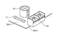
- FIG. 6 is a partially enlarged view of the electronic component mounting board in the electronic component mounting board according to Embodiment 1 of the present invention.
- the electronic component mounting board 26d shown in FIG. 6 is formed on the end part of the component mounting board 26d1 for mounting the electronic component, the discarded board 26d2 on which the electronic component is not mounted, and the component mounting board 26d1.
- a groove portion 26d3 formed between the substrate 26d2 and a terminal block 63 that is disposed between the component mounting substrate 26d1 and the discard substrate 26d2 across the groove portion 26d3 and fixed to the component mounting substrate 26d1;
- the substrate 26d2 is not in contact with the bottom surface portion of the terminal block 63 that is discarded from the groove portion 26d3 and protrudes toward the substrate 26d2.
- a terminal block 63, an electrolytic capacitor 70, and a fuse 71 are shown as electronic components.
- the discarded substrate 26d2 has a cutout hole 26d21 larger than the bottom surface portion of the terminal block 63 in a region where the bottom surface portion of the terminal block 63 protruding from the groove 26d3 is projected in the direction of the discarded substrate 26d2.
- FIG. 7 is a partial enlarged view of the component mounting board after the discarded board is cut off in the electronic component mounting board according to Embodiment 1 of the present invention.
- the terminal block 63 is installed so as to protrude from the end 26d11 on the short side of the component mounting board 26d1.
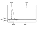
- FIG. 8 is a front view of the electronic component mounting board before mounting the electronic component in the electronic component mounting board according to Embodiment 1 of the present invention.
- the electronic component mounting board 26d has a rectangular shape including long sides facing each other and short sides facing each other in plan view. Two groove portions 26d3 extending from one short side to the other short side are engraved in the component mounting board 26d1.
- Two terminal insertion holes 26d12 are formed in the component mounting board 26d1 in parallel with the groove 26d3.
- the lead terminal 63d2 shown in FIG. 5 is inserted into each of the two terminal insertion holes 26d12.
- a rectangular cutout hole 26d21 is formed in the discard board 26d2 at a position facing the two terminal insertion holes 26d12.
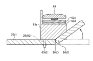
- FIG. 9 is a side view of the electronic component mounting board 26d showing a state where the discard board 26d2 is being bent in the electronic component mounting board 26d according to Embodiment 1 of the present invention.
- FIG. 9 shows a state in which the discarded board 26d2 is bent on the terminal block 63 side installed on the component mounting board 26d1.
- the discard board 26d2 has the cutout hole 26d21 larger than the bottom surface of the portion of the terminal block 63 that protrudes from the component mounting board 26d1. Therefore, as shown in FIG.
- the terminal block 63 enters the cutout hole 26d21, and the terminal block 63 does not interfere with the discarded board 26d2.
- the interference refers to a state in which the bent board 26d2 hits the terminal block 63. Accordingly, when the discard board 26d2 is separated from the component mounting board 26d1, not only the discard board 26d2 can be bent below the paper surface, but also the discard board 26d2 can be bent above the paper surface. The efficiency of the work of removing from the substrate 26d1 can be improved.
- the discarded board 26d2 can be folded alternately and repeatedly on the upper side and the lower side of the paper surface, so that compared to the case where the discarded board 26d2 is folded only on the lower side of the paper surface.
- the portion of the board in which the groove 26d3 is formed is easily damaged, and the discarded board 26d2 can be quickly separated from the component mounting board 26d1.
- FIG. FIG. 10 is a partially enlarged view of the electronic component mounting board in the electronic component mounting board according to Embodiment 2 of the present invention.
- a discarded board 26d2-1 that does not have the notched hole 26d21 is used instead of the discarded board 26d2 that has the notched hole 26d21 according to the first embodiment.
- the electronic component mounting board 26d-1 of the second embodiment has a spacer 72 installed between the terminal block 63 and the component mounting board 26d1, and the terminal block 63 is interposed between the component mounting board 26d1 and the spacer 72. Fixed to.
- the electronic component mounting board 26d-1 shown in FIG. 10 is formed on the component mounting board 26d1 on which the electronic component is mounted, on the end part of the component mounting board 26d1, and on the disposal board 26d2-1 on which the electronic component is not mounted.
- a stand 63 is provided.
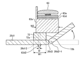
- FIG. 11 is a side view of the electronic component mounting board showing a state in the middle of bending the discarded board in the electronic component mounting board according to Embodiment 2 of the present invention.
- FIG. 11 shows a state where the discarded board 26d2-1 is bent on the terminal block 63 side installed on the component mounting board 26d1.
- the spacer 72 is installed between the terminal block 63 and the component mounting board 26d1, and has an insertion hole 72a for inserting the lead terminal 63d2.
- the spacer 72 has a width W1 in the direction from the component mounting board 26d1 to the discarded board 26d2-1 larger than the diameter D of the terminal insertion hole 26d12.
- the width W1 of the spacer 72 is formed to be narrower than the width W2 of the pedestal portion 63a in the direction from the component mounting board 26d1 to the discard board 26d2-1.
- the width from the central axis of the spacer 72 to the side surface on the groove 26d3 side is narrower than the width from the central axis of the terminal insertion hole 26d12 to the groove 26d3.
- the width W1 of the spacer 72 is desirably as wide as possible under these dimensional conditions in order to stably fix the terminal block 63 on the component mounting board 26d1.
- the spacer 72 configured in this way When the spacer 72 configured in this way is installed between the terminal block 63 and the component mounting board 26d1, the portion of the terminal block 63 installed on the component mounting board 26d1 that protrudes from the component mounting board 26d1 is discarded. It is separated from the substrate 26d2-1. Therefore, as shown in FIG. 11, when the discarded substrate 26d2-1 is bent above the paper surface, the terminal block 63 does not interfere with the substrate until the discarded substrate 26d2-1 is bent at a certain angle. Therefore, when the discard board 26d2-1 is separated from the component mounting board 26d1, the discard board 26d2-1 can be bent not only below the paper surface but also above the paper surface. The efficiency of the operation of removing from the component mounting board 26d1 can be improved.
- FIG. 12 is a partially enlarged view of the component mounting board after separating the discarded board in the electronic component mounting board according to Embodiment 2 of the present invention.
- the terminal block 63 is installed so as to protrude from the end 26d11 on the short side of the component mounting board 26d1.
- the terminal block 63 is fixed on the component mounting board 26d1 via the spacer 72.
- FIG. 13 is a diagram showing the inside of the electrical component box with the lid removed in the air conditioner according to Embodiment 3 of the present invention.
- an indoor unit 2A is used instead of the indoor unit 2 of the first embodiment.
- the indoor unit 2A includes a drain pan 24 and an electrical component box 26.
- a component mounting board 26d1 is installed in the electrical component box 26.
- a terminal block 33, a terminal block 53, and a terminal block 63 are provided on the component mounting board 26d1. Fixed. A part of each of the terminal block 33, the terminal block 53, and the terminal block 63 is supported by the terminal block support portion 80a.
- FIG. 14 is a cross-sectional view taken along the line AA shown in FIG. 13 in the electrical component box of the air conditioner according to Embodiment 3 of the present invention.
- the electrical component box 26 is provided with a substrate installation component 80 that is spaced apart from the electrical component box 26 and fixes the component mounting board 26 d 1 in the electrical component box 26.
- the board mounting component 80 includes a board support portion 80b that supports the component mounting board 26d1, and a terminal block support section 80a that supports a portion of the terminal block 63 installed on the component mounting board 26d1 that protrudes from the component mounting board 26d1. And have.
- the stress is distributed to the contact portion 7 between the terminal block 63 and the terminal block support portion 80a and the soldered portion between the lead terminal 63d2 and the component mounting board 26d1. Accordingly, the stress applied to the soldering portion is reduced, the strength reduction of the soldering portion can be suppressed, and the reliability can be improved.
- FIG. FIG. 15 is a diagram showing the inside of an electrical component box with the lid removed in the air conditioner according to Embodiment 4 of the present invention.
- an indoor unit 2B is used instead of the indoor unit 2 of the first embodiment.
- the indoor unit 2B includes a drain pan 24 and an electrical component box 26.
- a component mounting board 26d1 is installed in the electrical component box 26, and a terminal block 33, a terminal block 53, and a terminal block 63 are provided on the component mounting board 26d1. Fixed. A part of each of the terminal block 33, the terminal block 53, and the terminal block 63 is supported by the terminal block support portion 80c.
- FIG. 16 is a cross-sectional view taken along line AA shown in FIG. 15 in the electrical component box of the air conditioner according to Embodiment 4 of the present invention.
- the electrical component box 26 is provided with a board installation component 80 ⁇ / b> A that is spaced apart from the electrical component box 26 and fixes the component mounting board 26 d 1 in the electrical component box 26.
- the terminal block 63 is fixed to the component mounting board 26d1 via the spacer 72.
- the board mounting component 80A includes a board support portion 80b that supports the component mounting board 26d1, and a terminal block support section 80c that supports a portion of the terminal block 63 installed on the component mounting board 26d1 that protrudes from the component mounting board 26d1. And have.
- the terminal block support portion 80c shown in FIG. 16 is formed such that the width in the direction from the board installation component 80A toward the terminal block 63 is thicker than the terminal block support portion 80a of the third embodiment by the thickness of the spacer 72. .
- the terminal block support part 80c causes the terminal block Part of is supported. Therefore, the stress applied when the wiring is connected to the terminal block 63 is distributed to the contact portion 7 between the terminal block 63 and the terminal block support portion 80c, and the soldering portion between the lead terminal 63d2 and the component mounting board 26d1. Is done. Accordingly, the stress applied to the soldering portion is reduced, the strength reduction of the soldering portion can be suppressed, and the reliability can be improved.
- the screw type terminal block has been described as an example.
- the type of the terminal block is not limited to the screw type, and the electronic component mounting boards 26d and 26d of the first and second embodiments. -1 and the electrical component box of the air conditioner of the third and fourth embodiments can be applied to terminal blocks other than screw type such as tab type or spring lock type.
- the ceiling-embedded indoor unit is used.
- the electronic component mounting boards 26d and 26d-1 in the first and second embodiments are indoor units other than the ceiling-embedded type, for example, a ceiling-suspended type. It can also be applied to ceiling cassette type or wall-mounted type indoor units.
- the example of the electrical component box installed in the indoor unit of the air conditioner has been described.
- the electronic component mounting board of the first to fourth embodiments is installed in the outdoor unit of the air conditioner. It can also be applied to electrical component boxes.
- the electronic component mounting substrate according to the first to fourth embodiments can be applied to various devices other than the air conditioner as long as the device is mounted with a substrate on which a wiring terminal block is installed.
- the electronic component mounting boards 26d and 26d-1 are formed on the component mounting board 26d1 on which the electronic components are mounted and the end portions of the component mounting board 26d1.
- Board 26d2, 26d2-1 not mounted, groove portion 26d3 formed between component mounting board 26d1 and discard board 26d2, 26d2-1, and component mounting board 26d1 and waste board 26d2, 26d2 across the groove 26d3 -1 and terminal blocks 33, 53, 63 fixed to the component mounting board 26d1, and the discarded boards 26d2, 26d2-1 are disposed on the side of the discarded boards 26d2, 26d2-1 from the groove 26d3. There is no contact with the bottom surface of the protruding terminal blocks 33, 53, 63.
- the configuration described in the above embodiment shows an example of the contents of the present invention, and can be combined with another known technique, and can be combined with other configurations without departing from the gist of the present invention. It is also possible to omit or change the part.
Landscapes
- Engineering & Computer Science (AREA)
- Microelectronics & Electronic Packaging (AREA)
- Chemical & Material Sciences (AREA)
- Combustion & Propulsion (AREA)
- Mechanical Engineering (AREA)
- General Engineering & Computer Science (AREA)
- Air Filters, Heat-Exchange Apparatuses, And Housings Of Air-Conditioning Units (AREA)
- Structures For Mounting Electric Components On Printed Circuit Boards (AREA)
- Structure Of Printed Boards (AREA)
Abstract
La présente invention concerne une carte de circuit de montage de composant électronique (26d) qui comprend : une carte de circuit de montage de composant (26d1) pour monter un composant électronique ; une carte de déchet (26d2) formée au niveau d'une partie d'extrémité de la carte de circuit de montage de composant (26d1), aucun composant électronique n'étant monté sur la carte de déchet (26d2) ; une partie de rainure (26d3) formée entre la carte de circuit de montage de composant (26d1) et la carte de déchet (26d2) ; et une base de borne (63) installée entre la carte de circuit de montage de composant (26d1) et la carte de déchet (26d2) et couvrant la partie de rainure (26d3), la base de borne (63) étant fixée sur la carte de circuit de montage de composant (26d1). La carte de déchet (26d2) possède un trou d'encoche (26d21) qui est plus grand que la partie de surface inférieure de la base de borne (63) dans une région où la partie de surface inférieure de la base de borne (63) fait saillie dans la direction de la carte de déchet (26d2). La carte de déchet (26d2) n'a pas de contact avec la base de borne (63) en raison du trou d'encoche (26d21).
Priority Applications (3)
| Application Number | Priority Date | Filing Date | Title |
|---|---|---|---|
| PCT/JP2015/053951 WO2016129098A1 (fr) | 2015-02-13 | 2015-02-13 | Carte de circuit de montage de composant électronique et boîtier de pièces électriques pour climatiseur |
| CN201590000234.4U CN205883696U (zh) | 2015-02-13 | 2015-02-13 | 电子部件安装基板以及空调机的电气部件箱 |
| JP2016574593A JP6479057B2 (ja) | 2015-02-13 | 2015-02-13 | 電子部品実装基板および空気調和機の電気品箱 |
Applications Claiming Priority (1)
| Application Number | Priority Date | Filing Date | Title |
|---|---|---|---|
| PCT/JP2015/053951 WO2016129098A1 (fr) | 2015-02-13 | 2015-02-13 | Carte de circuit de montage de composant électronique et boîtier de pièces électriques pour climatiseur |
Publications (1)
| Publication Number | Publication Date |
|---|---|
| WO2016129098A1 true WO2016129098A1 (fr) | 2016-08-18 |
Family
ID=56614443
Family Applications (1)
| Application Number | Title | Priority Date | Filing Date |
|---|---|---|---|
| PCT/JP2015/053951 Ceased WO2016129098A1 (fr) | 2015-02-13 | 2015-02-13 | Carte de circuit de montage de composant électronique et boîtier de pièces électriques pour climatiseur |
Country Status (3)
| Country | Link |
|---|---|
| JP (1) | JP6479057B2 (fr) |
| CN (1) | CN205883696U (fr) |
| WO (1) | WO2016129098A1 (fr) |
Cited By (1)
| Publication number | Priority date | Publication date | Assignee | Title |
|---|---|---|---|---|
| CN110621140A (zh) * | 2019-09-20 | 2019-12-27 | 井翠红 | 一种无线电监测装置 |
Citations (6)
| Publication number | Priority date | Publication date | Assignee | Title |
|---|---|---|---|---|
| JPS63100889U (fr) * | 1986-12-19 | 1988-06-30 | ||
| JPH0521908A (ja) * | 1991-07-09 | 1993-01-29 | Canon Inc | 捨て板付プリント基板 |
| JP2000164993A (ja) * | 1998-11-26 | 2000-06-16 | Toshiba Corp | プリント配線板およびプリント配線板用母材 |
| JP2003092479A (ja) * | 2001-09-19 | 2003-03-28 | Yamatake Corp | プリント基板保持構造 |
| JP2008311360A (ja) * | 2007-06-13 | 2008-12-25 | Toyota Motor Corp | 端子の接続構造 |
| JP2011052959A (ja) * | 2010-12-20 | 2011-03-17 | Mitsubishi Electric Corp | 空気調和機 |
Family Cites Families (28)
| Publication number | Priority date | Publication date | Assignee | Title |
|---|---|---|---|---|
| JPS5428613Y2 (fr) * | 1974-03-12 | 1979-09-13 | ||
| JPS5361056U (fr) * | 1976-10-27 | 1978-05-24 | ||
| JPS54146861U (fr) * | 1978-04-04 | 1979-10-12 | ||
| JPS55107293A (en) * | 1980-01-09 | 1980-08-16 | Nippon Musical Instruments Mfg | Method of manufacturing device for mounting electric parts |
| JPS579180U (fr) * | 1980-06-17 | 1982-01-18 | ||
| JPS57168266U (fr) * | 1981-04-17 | 1982-10-23 | ||
| JPS59123973U (ja) * | 1983-02-08 | 1984-08-21 | 沖電気工業株式会社 | 端子台 |
| JPS6088576U (ja) * | 1983-11-24 | 1985-06-18 | シャープ株式会社 | プリント配線基板 |
| JPS62136895A (ja) * | 1985-12-11 | 1987-06-19 | 松下電器産業株式会社 | 端子台付電子回路装置 |
| JPH0342626Y2 (fr) * | 1985-12-13 | 1991-09-06 | ||
| JPS62157072U (fr) * | 1986-03-26 | 1987-10-06 | ||
| JPS6433768U (fr) * | 1987-08-24 | 1989-03-02 | ||
| JPH0221775U (fr) * | 1988-07-28 | 1990-02-14 | ||
| JPH0463490A (ja) * | 1990-07-03 | 1992-02-28 | Fujitsu Ltd | 可動部品のプリント板実装構造 |
| JPH04167490A (ja) * | 1990-10-30 | 1992-06-15 | Mitsubishi Electric Corp | プリント配線板 |
| JPH04199758A (ja) * | 1990-11-29 | 1992-07-20 | Casio Electron Mfg Co Ltd | 回路基板 |
| JPH05160539A (ja) * | 1991-12-05 | 1993-06-25 | Sony Corp | プリント基板およびその製造方法 |
| JP2548114Y2 (ja) * | 1991-12-12 | 1997-09-17 | 富士通株式会社 | 回路基板 |
| JPH0676872A (ja) * | 1992-08-28 | 1994-03-18 | Toshiba Corp | プリント配線基板 |
| JPH06169152A (ja) * | 1992-11-30 | 1994-06-14 | Hitachi Telecom Technol Ltd | 印刷配線板構造 |
| US5277596A (en) * | 1992-12-16 | 1994-01-11 | The Whitaker Corporation | Method of producing a card edge mounted connector and the resulting assembly thereof |
| US5407367A (en) * | 1993-09-27 | 1995-04-18 | Vernitron Corporation | Barrier terminal strip assembly |
| JPH08236181A (ja) * | 1995-02-28 | 1996-09-13 | Fuji Electric Co Ltd | アダプタ付き端子台 |
| JPH11230569A (ja) * | 1998-02-12 | 1999-08-27 | Mitsubishi Electric Corp | 天井埋込形空気調和装置 |
| JP2007120818A (ja) * | 2005-10-26 | 2007-05-17 | Mitsubishi Electric Corp | 空気調和機 |
| JP5283189B2 (ja) * | 2009-09-11 | 2013-09-04 | Necインフロンティア株式会社 | プリント基板 |
| US9437997B2 (en) * | 2013-04-26 | 2016-09-06 | Signalcraft Technologies | Process for attaching devices to a circuit board |
| JP6226810B2 (ja) * | 2014-05-12 | 2017-11-08 | 三菱電機株式会社 | 基板及びコネクタの位置ずれ規制方法 |
-
2015
- 2015-02-13 WO PCT/JP2015/053951 patent/WO2016129098A1/fr not_active Ceased
- 2015-02-13 JP JP2016574593A patent/JP6479057B2/ja not_active Expired - Fee Related
- 2015-02-13 CN CN201590000234.4U patent/CN205883696U/zh not_active Expired - Fee Related
Patent Citations (6)
| Publication number | Priority date | Publication date | Assignee | Title |
|---|---|---|---|---|
| JPS63100889U (fr) * | 1986-12-19 | 1988-06-30 | ||
| JPH0521908A (ja) * | 1991-07-09 | 1993-01-29 | Canon Inc | 捨て板付プリント基板 |
| JP2000164993A (ja) * | 1998-11-26 | 2000-06-16 | Toshiba Corp | プリント配線板およびプリント配線板用母材 |
| JP2003092479A (ja) * | 2001-09-19 | 2003-03-28 | Yamatake Corp | プリント基板保持構造 |
| JP2008311360A (ja) * | 2007-06-13 | 2008-12-25 | Toyota Motor Corp | 端子の接続構造 |
| JP2011052959A (ja) * | 2010-12-20 | 2011-03-17 | Mitsubishi Electric Corp | 空気調和機 |
Cited By (2)
| Publication number | Priority date | Publication date | Assignee | Title |
|---|---|---|---|---|
| CN110621140A (zh) * | 2019-09-20 | 2019-12-27 | 井翠红 | 一种无线电监测装置 |
| CN110621140B (zh) * | 2019-09-20 | 2020-12-18 | 井翠红 | 一种无线电监测装置 |
Also Published As
| Publication number | Publication date |
|---|---|
| JPWO2016129098A1 (ja) | 2017-04-27 |
| JP6479057B2 (ja) | 2019-03-06 |
| CN205883696U (zh) | 2017-01-11 |
Similar Documents
| Publication | Publication Date | Title |
|---|---|---|
| US6470699B1 (en) | Ceiling cassette type air conditioner | |
| JP3985834B2 (ja) | 電装品アセンブリ、それを備えた空気調和装置の室外ユニット、及び空気調和装置 | |
| CN205878524U (zh) | 空调机 | |
| CN206191781U (zh) | 空调机的室外机 | |
| JP5879534B2 (ja) | カバー、及び、空気調和装置の室外ユニット | |
| JP6479057B2 (ja) | 電子部品実装基板および空気調和機の電気品箱 | |
| JP5193000B2 (ja) | 空気調和機用室外機及びその組立方法 | |
| CN100436952C (zh) | 空调机的室内机 | |
| WO2020075243A1 (fr) | Unité extérieure pour climatiseur | |
| JP2004170054A (ja) | 空気調和機 | |
| JP4684796B2 (ja) | 空気調和機の室外機 | |
| JP2008144982A (ja) | 空気調和機の室外機 | |
| CN211600896U (zh) | 天花板悬吊型空调装置室内机 | |
| JP7069411B2 (ja) | 空気調和機の室内機 | |
| JP6019217B2 (ja) | 空気調和機 | |
| JP7112030B2 (ja) | 空気調和機の室外機 | |
| KR100339007B1 (ko) | 공기 조화기의 콘트롤 박스 | |
| JP2017150757A (ja) | 基板、及びこれを備えた空気調和装置、並びに基板の製造方法 | |
| JP4609436B2 (ja) | 空気調和装置 | |
| JP2015117859A (ja) | 空気調和機の室外機 | |
| JPH11211144A (ja) | 空気調和機の壁掛式室内ユニット | |
| WO2019159314A1 (fr) | Unité intérieure de climatiseur | |
| JP2000249362A (ja) | ビルトイン型空気調和機 | |
| JP6885128B2 (ja) | 端子台およびその端子台を取り付けた空気調和機 | |
| JPH0212501Y2 (fr) |
Legal Events
| Date | Code | Title | Description |
|---|---|---|---|
| 121 | Ep: the epo has been informed by wipo that ep was designated in this application |
Ref document number: 15881973 Country of ref document: EP Kind code of ref document: A1 |
|
| ENP | Entry into the national phase |
Ref document number: 2016574593 Country of ref document: JP Kind code of ref document: A |
|
| NENP | Non-entry into the national phase |
Ref country code: DE |
|
| 122 | Ep: pct application non-entry in european phase |
Ref document number: 15881973 Country of ref document: EP Kind code of ref document: A1 |