WO2017010441A1 - アタッチメントの連結装置 - Google Patents
アタッチメントの連結装置 Download PDFInfo
- Publication number
- WO2017010441A1 WO2017010441A1 PCT/JP2016/070371 JP2016070371W WO2017010441A1 WO 2017010441 A1 WO2017010441 A1 WO 2017010441A1 JP 2016070371 W JP2016070371 W JP 2016070371W WO 2017010441 A1 WO2017010441 A1 WO 2017010441A1
- Authority
- WO
- WIPO (PCT)
- Prior art keywords
- attachment
- connecting device
- hole
- alignment
- strut
- Prior art date
- Legal status (The legal status is an assumption and is not a legal conclusion. Google has not performed a legal analysis and makes no representation as to the accuracy of the status listed.)
- Ceased
Links
Images



Classifications
-
- B—PERFORMING OPERATIONS; TRANSPORTING
- B66—HOISTING; LIFTING; HAULING
- B66C—CRANES; LOAD-ENGAGING ELEMENTS OR DEVICES FOR CRANES, CAPSTANS, WINCHES, OR TACKLES
- B66C23/00—Cranes comprising essentially a beam, boom, or triangular structure acting as a cantilever and mounted for translatory of swinging movements in vertical or horizontal planes or a combination of such movements, e.g. jib-cranes, derricks, tower cranes
- B66C23/18—Cranes comprising essentially a beam, boom, or triangular structure acting as a cantilever and mounted for translatory of swinging movements in vertical or horizontal planes or a combination of such movements, e.g. jib-cranes, derricks, tower cranes specially adapted for use in particular purposes
- B66C23/26—Cranes comprising essentially a beam, boom, or triangular structure acting as a cantilever and mounted for translatory of swinging movements in vertical or horizontal planes or a combination of such movements, e.g. jib-cranes, derricks, tower cranes specially adapted for use in particular purposes for use on building sites; constructed, e.g. with separable parts, to facilitate rapid assembly or dismantling, for operation at successively higher levels, for transport by road or rail
- B66C23/34—Self-erecting cranes, i.e. with hoisting gear adapted for crane erection purposes
- B66C23/344—Self-erecting cranes, i.e. with hoisting gear adapted for crane erection purposes adapted for transport purposes
-
- F—MECHANICAL ENGINEERING; LIGHTING; HEATING; WEAPONS; BLASTING
- F16—ENGINEERING ELEMENTS AND UNITS; GENERAL MEASURES FOR PRODUCING AND MAINTAINING EFFECTIVE FUNCTIONING OF MACHINES OR INSTALLATIONS; THERMAL INSULATION IN GENERAL
- F16B—DEVICES FOR FASTENING OR SECURING CONSTRUCTIONAL ELEMENTS OR MACHINE PARTS TOGETHER, e.g. NAILS, BOLTS, CIRCLIPS, CLAMPS, CLIPS OR WEDGES; JOINTS OR JOINTING
- F16B7/00—Connections of rods or tubes, e.g. of non-circular section, mutually, including resilient connections
- F16B7/04—Clamping or clipping connections
- F16B7/0433—Clamping or clipping connections for rods or tubes being in parallel relationship
-
- B—PERFORMING OPERATIONS; TRANSPORTING
- B66—HOISTING; LIFTING; HAULING
- B66C—CRANES; LOAD-ENGAGING ELEMENTS OR DEVICES FOR CRANES, CAPSTANS, WINCHES, OR TACKLES
- B66C23/00—Cranes comprising essentially a beam, boom, or triangular structure acting as a cantilever and mounted for translatory of swinging movements in vertical or horizontal planes or a combination of such movements, e.g. jib-cranes, derricks, tower cranes
- B66C23/18—Cranes comprising essentially a beam, boom, or triangular structure acting as a cantilever and mounted for translatory of swinging movements in vertical or horizontal planes or a combination of such movements, e.g. jib-cranes, derricks, tower cranes specially adapted for use in particular purposes
- B66C23/26—Cranes comprising essentially a beam, boom, or triangular structure acting as a cantilever and mounted for translatory of swinging movements in vertical or horizontal planes or a combination of such movements, e.g. jib-cranes, derricks, tower cranes specially adapted for use in particular purposes for use on building sites; constructed, e.g. with separable parts, to facilitate rapid assembly or dismantling, for operation at successively higher levels, for transport by road or rail
-
- B—PERFORMING OPERATIONS; TRANSPORTING
- B66—HOISTING; LIFTING; HAULING
- B66C—CRANES; LOAD-ENGAGING ELEMENTS OR DEVICES FOR CRANES, CAPSTANS, WINCHES, OR TACKLES
- B66C23/00—Cranes comprising essentially a beam, boom, or triangular structure acting as a cantilever and mounted for translatory of swinging movements in vertical or horizontal planes or a combination of such movements, e.g. jib-cranes, derricks, tower cranes
- B66C23/18—Cranes comprising essentially a beam, boom, or triangular structure acting as a cantilever and mounted for translatory of swinging movements in vertical or horizontal planes or a combination of such movements, e.g. jib-cranes, derricks, tower cranes specially adapted for use in particular purposes
- B66C23/26—Cranes comprising essentially a beam, boom, or triangular structure acting as a cantilever and mounted for translatory of swinging movements in vertical or horizontal planes or a combination of such movements, e.g. jib-cranes, derricks, tower cranes specially adapted for use in particular purposes for use on building sites; constructed, e.g. with separable parts, to facilitate rapid assembly or dismantling, for operation at successively higher levels, for transport by road or rail
- B66C23/34—Self-erecting cranes, i.e. with hoisting gear adapted for crane erection purposes
- B66C23/346—Self-erecting cranes, i.e. with hoisting gear adapted for crane erection purposes with locking devices
-
- B—PERFORMING OPERATIONS; TRANSPORTING
- B66—HOISTING; LIFTING; HAULING
- B66C—CRANES; LOAD-ENGAGING ELEMENTS OR DEVICES FOR CRANES, CAPSTANS, WINCHES, OR TACKLES
- B66C23/00—Cranes comprising essentially a beam, boom, or triangular structure acting as a cantilever and mounted for translatory of swinging movements in vertical or horizontal planes or a combination of such movements, e.g. jib-cranes, derricks, tower cranes
- B66C23/62—Constructional features or details
- B66C23/64—Jibs
- B66C23/68—Jibs foldable or otherwise adjustable in configuration
-
- B—PERFORMING OPERATIONS; TRANSPORTING
- B66—HOISTING; LIFTING; HAULING
- B66C—CRANES; LOAD-ENGAGING ELEMENTS OR DEVICES FOR CRANES, CAPSTANS, WINCHES, OR TACKLES
- B66C2700/00—Cranes
- B66C2700/03—Cranes with arms or jibs; Multiple cranes
- B66C2700/0321—Travelling cranes
- B66C2700/0357—Cranes on road or off-road vehicles, on trailers or towed vehicles; Cranes on wheels or crane-trucks
- B66C2700/0378—Construction details related to the travelling, to the supporting of the crane or to the blocking of the axles; Outriggers; Coupling of the travelling mechamism to the crane mechanism
Definitions
- the present invention relates to a connecting device used when a plurality of long attachments such as struts constituting a work machine such as a crawler crane are stacked up and down.
- Patent Documents 1 and 2 there are those described in Patent Documents 1 and 2 below.
- connecting tools called fork ends and eye ends are fixed to opposing portions of a front mast and a rear mast that are stacked one above the other, and these connecting tools are connected by pins.
- lugs are respectively fixed to opposing portions of the intermediate boom that are stacked up and down, and these lugs are connected by a connecting pin.
- the above-described conventional technology has the following problems. Since the attachment fixing methods described in Patent Documents 1 and 2 both fix and pin a coupling tool such as a lug to the facing portion of the attachment stacked vertically, the height of the coupling tool is high. For some reason, the transportation height will be high.
- the present invention has been made in view of the above circumstances, and an object of the present invention is to reduce a height dimension when a plurality of long attachments constituting a work machine are stacked and fixed to each other, as compared with the prior art. It is an object to provide an attachment connecting device.
- the connecting device connects the first attachment and the second attachment constituting the work machine to each other.
- the connecting device includes a first connected part, a second connected part, and a connecting member.
- the first coupled portion extends outward from a first side surface extending along the longitudinal direction of the first attachment.
- the second connected portion extends outward from a second side surface extending along the longitudinal direction of the second attachment, and the first attachment and the second attachment are stacked on the first attachment.
- the first connection portion is disposed so as to face each other.
- the connecting member connects the first connected portion and the second connected portion.
- the height of the connecting device is determined by a plurality of long attachments constituting the work machine. Almost no effect on height when stacked vertically and fixed to each other. That is, the height dimension when the attachments are stacked vertically and fixed to each other is reduced as compared with the prior art.
- FIG. 2 is a cross-sectional view taken along the line AA in FIG. 1 and shows a state in which a connecting member is not mounted. It is a perspective view of the connection instrument of the connection apparatus shown in FIG. It is a perspective view of the position alignment part of the coupling device shown in FIG. It is a side view showing the state where a plurality of struts stacked up and down were connected by the connecting device concerning a 2nd embodiment of the present invention. It is the B section enlarged view of FIG.
- a luffing jib crane (not shown) that is a work machine (a crane with a jib attached to the tip of a boom) is disassembled and transported.
- the connecting device of the present invention provided on a long attachment constituting the crane can be used.
- the long attachment include struts, jibs, booms, and masts.
- FIG. 1 is a side view showing a state in which a plurality of struts stacked vertically are connected by a connecting device according to a first embodiment of the present invention.
- the long attachment constituting the luffing jib crane is disassembled and loaded on the trailer 50 in the form shown in FIG. 1, for example, and transported.
- the lower jib 2 shown in FIG. 1 constitutes the lower part of the jib attached to the tip of the boom (not shown) of the luffing jib crane.
- the front strut 3 shown by FIG. 1 comprises the 1st attachment of this invention
- the rear strut 4 comprises the 2nd attachment of this invention.
- Each of the front strut 3 and the rear strut 4 is rotatably attached to the tip of the jib of the luffing jib crane.
- the front strut 3 attached to the lower jib 2 via the pin 3A is folded on the lower jib 2
- the rear strut 4 is stacked on the front strut 3, so that the lower jib 2, front strut 3 and the rear strut 4 are transported together in one trailer 50.
- a posture in which the rear strut 4 is stacked on the front strut 3 is defined as a connected posture of the front strut 3 and the rear strut 4.
- the connecting device includes a connecting device 1.
- the front strut 3 and the rear strut 4 are connected to each other by a connecting device 1. It is desirable that a plurality of the connecting devices 1 be arranged at a predetermined interval in the longitudinal direction of the strut.
- the connecting devices 1 are arranged on the side surfaces of both ends in the longitudinal direction of the strut.
- the connection tool 1 is arrange
- the alignment portion 7 is disposed on the side surface of the strut and in the vicinity of each connection device 1 (with a predetermined space between the connection devices 1). Similar to the connecting device 1, the alignment portions 7 are arranged on both sides of the strut in the width direction, that is, a total of four alignment portions 7 are arranged in the present embodiment. In the present embodiment, a total of four coupling devices 1 and a total of four positioning portions 7 constitute a coupling device.
- FIG. 2 is a cross-sectional view taken along the line AA of FIG. 1, and shows a state in which a connecting pin 15 described later is not attached.
- the front strut 3 is a lattice strut, and includes four pipe members 21 extending in the longitudinal direction and a plurality of connecting members 22 for connecting the pipe members 21 as shown in FIG.
- the rear strut 4 is also a lattice strut. As shown in FIG. 2, the rear strut 4 includes four pipe members 31 extending in the longitudinal direction and a plurality of connecting members 32 for connecting the pipe members 31. Have.
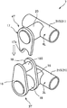
- FIG. 3 is a perspective view of the connecting device 1 of the connecting device shown in FIG.
- the connecting device 1 is provided on the side of the facing portion T (FIG. 2) when the front strut 3 and the rear strut 4 are laid down and stacked vertically (connected posture).
- the connecting device 1 of the present embodiment includes a first connected portion 3S, a second connected portion 4S, and a connecting pin 15.
- the first connected portion 3S extends outward from a first side surface 3L (FIGS. 2 and 3) extending along the longitudinal direction of the front strut 3.
- the first connected part 3S includes a first connecting support part 11 having a circular cross section and a predetermined length, and two connecting first plates 13.
- the two connecting first plates 13 constitute the first protrusion of the present invention.
- the second connected portion 4S extends outward from a second side surface 4L (FIGS. 2 and 3) extending along the longitudinal direction of the rear strut 4. Further, the second connected portion 4S is disposed to face the first connected portion 3S in the connecting posture of the front strut 3 and the rear strut 4 (FIGS. 1 to 3).
- the second coupled portion 4S includes a coupling second support portion 12 having a circular cross section and a predetermined length, and one coupling second plate 14.
- the connecting second plate 14 constitutes a second protrusion of the present invention.
- the connecting pin 15 functions as a connecting member that connects and connects the two connecting first plates 13 and the connecting second plate 14 from the side.
- the first connected portion 3S, the second connected portion 4S, and the connecting pin 15 constitute the connecting device 1 that connects the front strut 3 and the rear strut 4.
- the first connecting portion 11 for connection is outward from the side surface of the pipe member 21S (FIGS. 2 and 3) on the side close to the rear strut 4 of the pipe members 21 constituting the front strut 3 when stacked. It is provided in the side surface of the said pipe member 21S so that it may extend toward.
- the second support portion 12 for connection is outward from the side surface of the pipe member 31S (FIGS. 2 and 3) on the side close to the front strut 3 of the pipe members 31 constituting the rear strut 4 when stacked. It is provided in the side surface of the said pipe member 31S so that it may extend toward.
- the two connecting first plates 13 are protruded upward from the connecting first support portion 11 by being externally fixed to the connecting first support portion 11 with a gap therebetween. At this time, as shown in FIG. 2, the two connecting first plates 13 are arranged to extend upward from the front strut 3.
- the second connecting plate 14 is protruded downward from the second connecting support portion 12 by being externally fixed to the second connecting support portion 12. At this time, as shown in FIG. 2, one connecting second plate 14 is arranged to extend downward from the rear strut 4. Further, as shown in FIG. 3, the connecting second plate 14 has a width direction of the rear strut 4 that intersects the vertical direction and the longitudinal direction of the rear strut 4 (direction perpendicular to the paper surface of FIG. 1, right and left of FIG. 2).
- the upper and lower directions are directions when the rear strut 4 is stacked on the front strut 3 laid sideways.
- the second connecting plate 14 enters the gap between the two first connecting plates 13.
- a pin hole 13a and a pin hole 14a are formed in the first connecting plate 13 and the second connecting plate 14, respectively (see FIG. 3).
- the pin hole 13a and the pin hole 14a are opened so as to penetrate the first connecting plate 13 and the second connecting plate 14 along the width direction, respectively.
- the pin hole 13a and the pin hole 14a constitute a first hole part and a second hole part of the present invention, respectively.
- the connecting pin 15 (FIG.
- FIG. 4 is a perspective view of the alignment portion 7 of the coupling device shown in FIG.
- the alignment portion 7 regulates the relative position of the rear strut 4 with respect to the front strut 3 so that the pin hole 14a faces the pin hole 13a in the width direction in the connection posture.
- the alignment part 7 is provided on the side of the facing part T (FIG. 2) when the front strut 3 and the rear strut 4 are laid down side by side and stacked up and down in the same manner as the connecting device 1 described above.
- the alignment unit 7 includes a first alignment member 3T and a second alignment member 4T.
- the first alignment member 3T is disposed on the first side surface 3L of the front strut 3 (FIG. 4).
- the first alignment member 3T is fixed between the first alignment support portion 19 having a circular cross section and a predetermined length, the two alignment plates 16, and the two alignment plates 16.
- the second alignment member 4T is disposed on the second side surface 4L of the rear strut 4 (FIG. 4).
- the second alignment member 4T includes an alignment second support portion 20 having a circular cross section and a predetermined length, and one engagement plate 17.
- the alignment unit 7 is an instrument for aligning the positions of the pin holes 13 a of the first connecting plate 13 and the pin holes 14 a of the second connecting plate 14.
- the first support portion 19 for alignment extends outward from the side surface of the pipe member 21 ⁇ / b> S on the side close to the rear strut 4 of the pipe members 21 constituting the front strut 3 when stacked.
- the second support portion 20 for alignment extends outward from the side surface of the pipe member 31S on the side close to the front strut 3 of the pipe members 31 constituting the rear strut 4 when stacked. Is provided on the side surface of the pipe member 31S.
- the two alignment plates 16 are protruded upward from the alignment first support portion 19 by being externally fixed to the alignment first support portion 19 with a gap therebetween.
- the engagement plate 17 is protruded downward from the second alignment support portion 20 by being externally fixed to the second alignment support portion 20. Further, when the rear strut 4 is stacked on the front strut 3, the engagement plate 17 enters the gap between the two alignment plates 16.
- the positioning guide 18 has a cylindrical shape extending along the width direction of the front strut 3. Further, an arcuate recess 17 a is provided at the end of the engagement plate 17.
- the recessed portion 17a is formed so as to face the outer peripheral surface 18S of the positioning guide 18 in the up-down direction when the front strut 3 and the rear strut 4 are connected.
- the inner peripheral surface of the recess 17a and the outer peripheral surface 18S of the positioning guide 18 have the same diameter so as to come into surface contact with each other.
- the concave portion 17 a of the engagement plate 17 is placed on the positioning guide 18. That is, the concave portion 17a of the engagement plate 17 and the outer peripheral surface 18S of the positioning guide 18 are engaged with each other.
- the rear strut 4 is placed on the front strut 3 (a state in which the rear strut 4 is placed), and the relative position of the rear strut 4 with respect to the front strut 3 is restricted in the longitudinal direction and the vertical direction of the front strut 3.
- the holes of the pin hole 13a and the pin hole 14a are combined, and the two holes are in agreement with each other when viewed from the side.
- each component of the alignment portion 7 is arranged on the side surface of each strut so that the pin hole 13a and the pin hole 14a have such a positional relationship.
- the outer peripheral surface 18S of the positioning guide 18 and the recess 17a of the engagement plate 17 are brought into contact with each other by the weight of the rear strut 4 so that the relative positions of the pin hole 13a and the pin hole 14a in the vertical direction. To regulate.
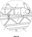
- FIG. 5 is a side view showing a state in which a plurality of struts stacked vertically are connected by the connecting device according to the second embodiment of the present invention.
- FIG. 6 is an enlarged view of a portion B in FIG. In the description of the second embodiment, the same parts and members as those described in the first embodiment shown in FIG.
- the upper boom 5 shown in FIG. 5 constitutes the upper end portion of the boom of a luffing jib crane (not shown).
- the lower jib 2, the front strut 3, and the rear strut 4 respectively connected to the upper boom 5 via pins 2A, 3A, and 4A are transported together by a single trailer 50.
- the connecting device shown in the present embodiment is an upper surface of the front strut 3 with a predetermined interval between a pair of connecting devices 1 provided on the side surfaces of both ends in the width direction of the strut and the connecting device 1 in the longitudinal direction of the strut. And a set of receiving plates 6 fixed to the base plate.
- the receiving plate 6 constitutes a receiving part of the present invention.
- the receiving plate 6 is fixed to the upper surface of the pipe member 21 on the side close to the rear strut 4 when stacked, out of the pipe members 21 constituting the front strut 3.
- the receiving plate 6 is also disposed at a corresponding position on the back side of the drawing in FIGS.
- the receiving plate 6 When the rear strut 4 pinned to the upper boom 5 is tilted with the pinned portion (pin 4A) as a fulcrum, the receiving plate 6 has the tip of the rear strut 4 positioned above the front strut 3.
- the pipe member 21 is fixed in advance to the upper surface of the pipe member 21 at a location where it hits the pipe member 21.
- the tip end portion of the rear strut 4 abuts against the receiving plate 6 from above, so that the pipe member 21 constituting the front strut 3 is prevented from being damaged.
- the front strut 3 and the rear strut 4 are connected by a pin 4A via an upper boom 5 and are also connected by a connecting device 1 as shown in FIG. That is, since the front strut 3 and the rear strut 4 are connected to each other at two locations in the longitudinal direction of each strut, the rear strut 4 is sufficiently prevented from collapsing from the front strut 3 during transportation.
- the second connecting plate 14 is inserted into the gap between the two first connecting plates 13, but one connecting first plate 13 is provided.
- the connection first plate 13 and the connection second plate 14 may be connected by the connection pin 15.
- bolts and nuts may be used in place of the connection pins 15 described above, and the first plate for connection 13 and the second plate for connection 14 may be connected and fixed with bolts and nuts.
- a positioning guide 18 is disposed on the side of the front strut 3 and an engagement plate 17 is disposed on the side of the rear strut 4. 17 may be disposed, and a positioning guide 18 may be disposed on the side of the rear strut 4.
- Only one alignment plate 16 may be provided.
- the engagement plate 17 is set so as to extend longer than that shown in FIG. 4, the inner diameter of the recess 17 a is set in accordance with the outer diameter of the alignment first support portion 19, and the positioning guide 18. May be omitted. In this manner, the recess 17a of the engagement plate 17 may be engaged with the outer peripheral surface of the columnar first alignment support 19.
- the first alignment portion 19 for alignment is a member provided with the outer peripheral surface of the first alignment member 3T with which the concave portion 17a of the engagement plate 17 is engaged.
- the receiving plate 6 may be omitted. However, if the receiving plate 6 exists, when the rear strut 4 falls on the front strut 3, the front end portion of the rear strut 4 can be received by the receiving plate 6. Thereby, it is preferable that the front strut 3 is prevented from being damaged.
- the strut (attachment) to be connected may be not a lattice structure but a box structure (a cross section is composed of four plates). Note that the lattice structure is lighter, has higher rigidity, and higher strength than the box structure.
- the coupling device of the coupling device is provided on the side surface of the long attachment (for example, strut).
- the height of the connecting device hardly affects the height dimension when a plurality of long attachments constituting a work machine (for example, a crane) are stacked and fixed to each other. That is, according to this invention, the height dimension when attaching attachments up and down and mutually fixing can be reduced compared with the past. Thereby, the transport height at the time of transporting an attachment piled up and down can be restrained lower than before. Thereby, in a large crane, since more attachments can be transported collectively (or collectively transported), the number of trailers can be reduced, and transportation cost is reduced.
- the frame size of the attachment (for example, struts) can be ensured in a range that does not exceed the transport limit height.
- the first connecting plate 13 projecting upward from the first connecting support portion 11 and the second connecting plate projecting downward from the second connecting support portion 12 are provided.
- the first support portion 11 for connection and the second connection member are connected to each other by the two plates 14, the connection rod-like member (for example, the connection pin 15) that connects the first connection plate 13 and the second connection plate 14 from the side.
- a pin hole 13a (first hole) that is provided on a side surface of the attachment and into which a connection pin 15 (connection member) formed on the first plate for connection 13 is inserted; It is preferable to provide an alignment portion 7 for aligning with a pin hole 14a (second hole portion) into which the connection pin 15 (connection member) formed in the second connection plate 14 is inserted. According to this configuration, the pin holes (first hole portion, second hole portion) can be easily aligned.
- the above-described alignment unit 7 includes a first alignment member (for example, the positioning guide 18) disposed on one side of the stacked attachments and a first alignment disposed on the other side. It is preferable to include a second alignment member (for example, the engagement plate 17) having a recess that engages with the member. According to this configuration, the alignment unit 7 can be configured with a simple configuration.
- the connecting support portions 11 and 12 of the connecting device 1 and the alignment support portions 19 and 20 of the alignment portion 7 have the same shape and dimensions. Further, the connecting plates 13 and 14 of the connecting device 1 and the alignment plate 16 and the engagement plate 17 of the alignment unit 7 are similar in shape. Since the parts are shared in this way, the cost can be reduced.
- a plurality of connecting devices 1 it is preferable to arrange a plurality of connecting devices 1 at a predetermined interval in the longitudinal direction of the attachment.
- the receiving plate 6 with which the longitudinal end portion of the second attachment, which is the upper attachment, abuts from above is disposed at a predetermined distance from the connecting device 1 in the longitudinal direction of the attachment. It is preferable to open and fix to the upper surface of the first attachment which is the lower attachment. According to this configuration, it is possible to prevent the attachment from being damaged by contact between the attachments.
Landscapes
- Engineering & Computer Science (AREA)
- Mechanical Engineering (AREA)
- Transportation (AREA)
- Structural Engineering (AREA)
- General Engineering & Computer Science (AREA)
- Jib Cranes (AREA)
Priority Applications (3)
| Application Number | Priority Date | Filing Date | Title |
|---|---|---|---|
| SG11201800331SA SG11201800331SA (en) | 2015-07-16 | 2016-07-11 | Connecting device for attachments |
| EP16824421.8A EP3323768B1 (de) | 2015-07-16 | 2016-07-11 | Verbindungsvorrichtung für zubehör |
| US15/745,279 US10704579B2 (en) | 2015-07-16 | 2016-07-11 | Connecting device for attachments |
Applications Claiming Priority (2)
| Application Number | Priority Date | Filing Date | Title |
|---|---|---|---|
| JP2015141812A JP6160660B2 (ja) | 2015-07-16 | 2015-07-16 | アタッチメントの連結装置 |
| JP2015-141812 | 2015-07-16 |
Publications (1)
| Publication Number | Publication Date |
|---|---|
| WO2017010441A1 true WO2017010441A1 (ja) | 2017-01-19 |
Family
ID=57757467
Family Applications (1)
| Application Number | Title | Priority Date | Filing Date |
|---|---|---|---|
| PCT/JP2016/070371 Ceased WO2017010441A1 (ja) | 2015-07-16 | 2016-07-11 | アタッチメントの連結装置 |
Country Status (5)
| Country | Link |
|---|---|
| US (1) | US10704579B2 (de) |
| EP (1) | EP3323768B1 (de) |
| JP (1) | JP6160660B2 (de) |
| SG (1) | SG11201800331SA (de) |
| WO (1) | WO2017010441A1 (de) |
Families Citing this family (3)
| Publication number | Priority date | Publication date | Assignee | Title |
|---|---|---|---|---|
| JP6805859B2 (ja) * | 2017-02-08 | 2020-12-23 | コベルコ建機株式会社 | ジブ係留装置の取付構造 |
| JP7358854B2 (ja) * | 2019-09-02 | 2023-10-11 | コベルコ建機株式会社 | 構造物保持装置 |
| JP7608773B2 (ja) | 2020-10-13 | 2025-01-07 | コベルコ建機株式会社 | ジブ固定装置 |
Citations (3)
| Publication number | Priority date | Publication date | Assignee | Title |
|---|---|---|---|---|
| JPS5830682U (ja) * | 1981-08-21 | 1983-02-28 | 日立建機株式会社 | 移動式タワ−クレ−ン |
| JPH11165986A (ja) * | 1997-12-02 | 1999-06-22 | Nippon Sharyo Seizo Kaisha Ltd | クレーンの中間ブーム |
| WO2010024151A1 (ja) * | 2008-08-29 | 2010-03-04 | 株式会社 タダノ | ジブ付きクレーン車のジブ格納装置 |
Family Cites Families (15)
| Publication number | Priority date | Publication date | Assignee | Title |
|---|---|---|---|---|
| US1941952A (en) * | 1931-12-26 | 1934-01-02 | Manitowoc Shipbuilding Corp | Boom construction |
| US2975910A (en) * | 1958-06-06 | 1961-03-21 | Clark Equipment Co | Crane boom |
| US3085695A (en) * | 1961-03-23 | 1963-04-16 | Carl A Miller | Hinge for crane boom |
| US3306470A (en) * | 1965-01-25 | 1967-02-28 | Robert A Green | Folding boom for mobile cranes |
| DE1297834B (de) * | 1967-03-11 | 1969-06-19 | E H Hans Dr Ing | Fahrbarer Mehrzweckkran |
| US3511388A (en) * | 1967-09-18 | 1970-05-12 | Manitowoc Co | Pin connection for elongate load supporting boom structure |
| US4016974A (en) * | 1974-11-08 | 1977-04-12 | Hans Tax | Package for transporting units of a modular crane |
| JPS61101593U (de) | 1984-12-07 | 1986-06-28 | ||
| US5193698A (en) | 1990-09-13 | 1993-03-16 | Kabushiki Kaisha Kobe Seiko Sho | Jib stretching and folding device for use in a crane |
| US5199586A (en) * | 1991-07-25 | 1993-04-06 | The Manitowoc Company, Inc. | Quick-connect sectional boom members for cranes and the like |
| JPH1111877A (ja) | 1997-06-24 | 1999-01-19 | Tadano Ltd | 車両搭載クレーンのジブ格納装置 |
| JP2004018251A (ja) | 2002-06-20 | 2004-01-22 | Sumitomo Heavy Industries Construction Crane Co Ltd | クレーン用中間ブーム |
| JP2009149438A (ja) * | 2007-11-29 | 2009-07-09 | Manitowoc Crane Companies Ltd | クレーンブームセグメント用の接続システム |
| US8839966B2 (en) * | 2009-03-31 | 2014-09-23 | Manitowoc Crane Companies, Llc | Folding jib main strut and transportable reeved strut caps |
| US20140131300A1 (en) * | 2012-11-09 | 2014-05-15 | Gru Comedil S.R.L. | Jib for a crane |
-
2015
- 2015-07-16 JP JP2015141812A patent/JP6160660B2/ja active Active
-
2016
- 2016-07-11 EP EP16824421.8A patent/EP3323768B1/de active Active
- 2016-07-11 SG SG11201800331SA patent/SG11201800331SA/en unknown
- 2016-07-11 WO PCT/JP2016/070371 patent/WO2017010441A1/ja not_active Ceased
- 2016-07-11 US US15/745,279 patent/US10704579B2/en active Active
Patent Citations (3)
| Publication number | Priority date | Publication date | Assignee | Title |
|---|---|---|---|---|
| JPS5830682U (ja) * | 1981-08-21 | 1983-02-28 | 日立建機株式会社 | 移動式タワ−クレ−ン |
| JPH11165986A (ja) * | 1997-12-02 | 1999-06-22 | Nippon Sharyo Seizo Kaisha Ltd | クレーンの中間ブーム |
| WO2010024151A1 (ja) * | 2008-08-29 | 2010-03-04 | 株式会社 タダノ | ジブ付きクレーン車のジブ格納装置 |
Non-Patent Citations (1)
| Title |
|---|
| See also references of EP3323768A4 * |
Also Published As
| Publication number | Publication date |
|---|---|
| JP6160660B2 (ja) | 2017-07-12 |
| EP3323768A4 (de) | 2018-10-03 |
| US20190032690A1 (en) | 2019-01-31 |
| JP2017024813A (ja) | 2017-02-02 |
| EP3323768A1 (de) | 2018-05-23 |
| EP3323768B1 (de) | 2020-04-08 |
| US10704579B2 (en) | 2020-07-07 |
| SG11201800331SA (en) | 2018-02-27 |
Similar Documents
| Publication | Publication Date | Title |
|---|---|---|
| US9458606B2 (en) | Boom apparatus with protective barrier for flexible line | |
| WO2017010441A1 (ja) | アタッチメントの連結装置 | |
| JP2016108118A (ja) | カウンタウエイト装置および作業機械 | |
| EP3556717B1 (de) | Baumaschine | |
| AU2019268668B2 (en) | Lattice structure, lattice structure coupling body, work machine, and connector | |
| US11142437B2 (en) | Rising and falling body of work machine and method for storing rising and falling body of work machine | |
| JP2008280166A (ja) | ジブ格納装置 | |
| CN106715316A (zh) | 起重机 | |
| CN204454344U (zh) | 一种臂架装置及工程机械 | |
| JP6540652B2 (ja) | 着脱機構 | |
| KR20150027989A (ko) | 크레인용 보조공구 | |
| JP7358854B2 (ja) | 構造物保持装置 | |
| JP6778415B2 (ja) | 移動式クレーン | |
| JP6837885B2 (ja) | ピン結合装置 | |
| US11787672B2 (en) | Lattice structure, lattice structure coupling body, work machine, and connector | |
| CN103407911A (zh) | 一种正面吊运起重机的起重装置及正面吊运起重机 | |
| JP2015147463A (ja) | クローラ式車両 | |
| JP7380686B2 (ja) | 伸縮ブーム及び作業機 | |
| EP4406907B1 (de) | Kran | |
| JP7435580B2 (ja) | コネクタ格納装置 | |
| JP7314673B2 (ja) | ブーム支持構造 | |
| JP2017039590A (ja) | 建設機械およびカーボディウエイトの取付方法 | |
| JP6562040B2 (ja) | 建設機械 | |
| CN107735351A (zh) | 伸缩起重臂的安装构造 | |
| KR101497550B1 (ko) | 구조물 인양용 러그 |
Legal Events
| Date | Code | Title | Description |
|---|---|---|---|
| 121 | Ep: the epo has been informed by wipo that ep was designated in this application |
Ref document number: 16824421 Country of ref document: EP Kind code of ref document: A1 |
|
| WWE | Wipo information: entry into national phase |
Ref document number: 11201800331S Country of ref document: SG |
|
| NENP | Non-entry into the national phase |
Ref country code: DE |
|
| WWE | Wipo information: entry into national phase |
Ref document number: 2016824421 Country of ref document: EP |