WO2017017968A1 - Amortisseur - Google Patents
Amortisseur Download PDFInfo
- Publication number
- WO2017017968A1 WO2017017968A1 PCT/JP2016/050099 JP2016050099W WO2017017968A1 WO 2017017968 A1 WO2017017968 A1 WO 2017017968A1 JP 2016050099 W JP2016050099 W JP 2016050099W WO 2017017968 A1 WO2017017968 A1 WO 2017017968A1
- Authority
- WO
- WIPO (PCT)
- Prior art keywords
- shock absorber
- case
- orifice
- cylinder
- hole
- Prior art date
- Legal status (The legal status is an assumption and is not a legal conclusion. Google has not performed a legal analysis and makes no representation as to the accuracy of the status listed.)
- Ceased
Links
Images


Classifications
-
- F—MECHANICAL ENGINEERING; LIGHTING; HEATING; WEAPONS; BLASTING
- F16—ENGINEERING ELEMENTS AND UNITS; GENERAL MEASURES FOR PRODUCING AND MAINTAINING EFFECTIVE FUNCTIONING OF MACHINES OR INSTALLATIONS; THERMAL INSULATION IN GENERAL
- F16F—SPRINGS; SHOCK-ABSORBERS; MEANS FOR DAMPING VIBRATION
- F16F9/00—Springs, vibration-dampers, shock-absorbers, or similarly-constructed movement-dampers using a fluid or the equivalent as damping medium
- F16F9/32—Details
- F16F9/44—Means on or in the damper for manual or non-automatic adjustment; such means combined with temperature correction
-
- F—MECHANICAL ENGINEERING; LIGHTING; HEATING; WEAPONS; BLASTING
- F16—ENGINEERING ELEMENTS AND UNITS; GENERAL MEASURES FOR PRODUCING AND MAINTAINING EFFECTIVE FUNCTIONING OF MACHINES OR INSTALLATIONS; THERMAL INSULATION IN GENERAL
- F16F—SPRINGS; SHOCK-ABSORBERS; MEANS FOR DAMPING VIBRATION
- F16F9/00—Springs, vibration-dampers, shock-absorbers, or similarly-constructed movement-dampers using a fluid or the equivalent as damping medium
- F16F9/32—Details
- F16F9/34—Special valve constructions; Shape or construction of throttling passages
- F16F9/346—Throttling passages in the form of slots arranged in cylinder walls
-
- F—MECHANICAL ENGINEERING; LIGHTING; HEATING; WEAPONS; BLASTING
- F16—ENGINEERING ELEMENTS AND UNITS; GENERAL MEASURES FOR PRODUCING AND MAINTAINING EFFECTIVE FUNCTIONING OF MACHINES OR INSTALLATIONS; THERMAL INSULATION IN GENERAL
- F16F—SPRINGS; SHOCK-ABSORBERS; MEANS FOR DAMPING VIBRATION
- F16F2230/00—Purpose; Design features
- F16F2230/18—Control arrangements
- F16F2230/186—Control arrangements with manual adjustments
Definitions
- the present invention relates to a shock absorber for reducing an impact force applied to a moving member when the moving member is stopped.
- a shock absorber ie, a shock absorber, is used to reduce the impact force applied to the moving member when the moving member is stopped at the position of the moving end.
- the hydraulic shock absorber described in Patent Literature 1 has an outer case filled with oil and a damper case mounted in the outer case, and the oil flows between the outer case and the damper case.
- a passage is formed.
- a piston is mounted in the damper case so as to be capable of reciprocating in the axial direction, and a piston rod attached to the piston projects outward from the tip of the outer case.
- the passage resistance of oil is applied to the piston as a drag force, the kinetic energy of the moving member is absorbed by the drag force of the oil, and the impact force applied to the moving member is alleviated.
- a needle shaft for changing the flow rate of oil flowing from the orifice to the passage is provided on the rear wall of the outer case, and the needle shaft is fixed by a nut.
- the fluid pressure type shock absorber described in Patent Literature 2 has a reservoir tube as an outer case and a pressure tube incorporated therein, and a throttle hole through which pressure oil in the pressure tube flows out is provided in the inner cover of the pressure tube. Is provided.
- An eccentric cam for adjusting the buffer characteristic by changing the area of the opening of the throttle hole is provided at the bottom of the reservoir tube, and the eccentric cam is fixed by a lock screw.
- Patent Document 3 describes a hydraulic shock absorber for buffering vehicle vibration, and a compression coil spring is attached to the outside of the hydraulic shock absorber.
- This hydraulic shock absorber has an outer cylinder and an inner cylinder.
- a piston is mounted in the inner cylinder so as to be capable of reciprocating in the axial direction, and a piston rod attached to the piston projects outside.
- the rod guide body is provided with an orifice passage in the inner cylinder that communicates between the reservoir chamber formed between the outer cylinder and the inner cylinder and the rod side oil chamber in the inner cylinder. Is fitted into the inner cylinder, and a plurality of orifices are provided in the rod guide body.
- the rotation angle of the rod guide body is regulated by a rotation regulating pin.
- the needle shaft is fixed by a nut.
- the eccentric cam is fixed with a lock screw after adjusting the area of the opening of the throttle hole with the eccentric cam.
- An object of the present invention is to provide a shock absorber excellent in operability by easily adjusting the buffer characteristics.
- a piston rod is mounted so as to be capable of reciprocating in the axial direction, and is supported by a case filled with liquid and a base end portion of the case so as to be rotatable and movable in the axial direction.
- a rotation operation part a rotation cylinder provided with a cylinder part, and a piston that is provided at a proximal end part of the piston rod, partitions the cylinder part into a rear chamber and a front chamber, and is attached to the rear chamber;
- a spring member that abuts on the rotating cylinder and biases a spring force in a direction in which the protruding end of the piston rod protrudes from the tip of the case, and an orifice that changes depending on the position of the rotating operation unit in the rotating direction
- the step surface of the rotating cylinder and the stopper surface of the case are in contact with each other.
- the shock absorber has a case and a rotating cylinder that is rotatably mounted inside the case. Inside the cylinder portion of the rotating cylinder, a front chamber and a rear chamber are separated by a piston provided at a base end portion of the piston rod. It is divided into. A spring member that biases the spring force in the direction in which the piston rod protrudes is provided in the rear chamber, and the opening of the orifice changes depending on the position of the rotation operation unit in the rotation direction. Therefore, when the rotation cylinder is rotated by the rotation operation unit, the communication opening degree of the orifice can be easily adjusted. Thereby, it is possible to easily adjust the shock absorber shock absorbing characteristics.
- the step surface of the rotating cylinder is in contact with the stopper surface of the case, the impact and force applied to the rotating cylinder are transmitted from the rotating cylinder to the case and not to other members. Thereby, the durability of the shock absorber is improved.
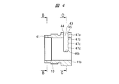
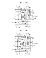
- FIG. 4 is a sectional view taken along line AA in FIG. 3.
- FIG. 5 is a sectional view taken along line BB in FIG. It is CC sectional view taken on the line in FIG.
- FIG. 8 is a sectional view taken along line DD in FIG.
- FIG. 8 is a right side view of FIG. 7.
- It is the EE sectional view taken on the line in FIG. (A) is sectional drawing which shows the base end part of the case shown by FIG.
- (B) is the base of the case in the state which moved the rotation cylinder to the axial direction, when adjusting the communicating opening degree of an orifice. It is sectional drawing which shows an edge part. It is a longitudinal cross-sectional view which shows the shock absorber which is other embodiment. It is a right view of FIG. It is a longitudinal cross-sectional view which shows the shock absorber which is other embodiment. It is a right view of FIG. It is sectional drawing which shows a part of shock absorber which is other embodiment. It is sectional drawing which shows a part of shock absorber which is other embodiment. It is a top view which shows the rotation cylinder of the shock absorber which is other embodiment. It is a top view which shows the base case of the shock absorber which is other embodiment. FIG.
- FIG. 20 is a sectional view taken along line FF in FIG. 19. It is the GG sectional view taken on the line in FIG. FIG. 20 is a cross-sectional view taken along the line HH in FIG.
- FIG. 20 is a plan view of a rotating cylinder to which the base case shown in FIG. 19 is assembled. It is the II sectional view taken on the line in FIG. It is a top view which shows the rotation cylinder of the shock absorber which is other embodiment. It is the JJ sectional view taken on the line in FIG. FIG. 26 is a sectional view taken along line KK in FIG. 25. It is a longitudinal cross-sectional view which shows the shock absorber which is other embodiment.
- the shock absorber 10 has a case 11 including a cylindrical main case 11a and a base case 11b fixed to a base end portion of the main case 11a.
- a female screw 12 is provided at the base end portion of the main case 11a
- a male screw 13 screwed to the female screw 12 is provided at the base case 11b
- the base case 11b is screwed to the main case 11a.
- Rotating cylinder 14 is mounted in the base end of case 11.
- the rotation cylinder 14 includes a rotation operation unit 15 that is supported by the base case 11b so as to be rotatable and movable in the axial direction, and a cylinder unit 16 that is integrated with the distal end side of the rotation operation unit 15. ing.
- the rotation operation unit 15 includes a cylindrical portion 17 that is fitted to the inner peripheral surface of the base case 11b, and a blocking wall 18 that is provided at a central portion in the axial direction of the cylindrical portion 17.
- a step surface 19 in the radial direction is provided between the cylinder portion 16 and the cylindrical portion 17, and the step surface 19 abuts against a stopper surface 20 provided on the distal end side of the base case 11 b.
- the holder 21 is mounted in the tip of the case 11.
- the holder 21 has a cylindrical portion 22, and a flange 23 is integrally provided at the tip of the cylindrical portion 22, and a flange 24 is integrally provided at the rear end of the cylindrical portion 22.
- the piston rod 25 is attached to the holder 21 so as to be reciprocally movable in the axial direction, and the tip of the piston rod 25 protrudes from the tip of the case 11.
- the rod cover 26 is attached to the tip of the case 11, and the flange 23 of the holder 21 contacts the inner surface of the rod cover 26.
- the shock absorber 10 has an end portion from which the piston rod 25 protrudes as a distal end portion and an opposite end portion as a proximal end portion.
- the inside of the case 11 is filled with hydraulic oil, that is, liquid.
- hydraulic oil that is, liquid.
- an injection hole 27 is provided in the closing wall 18 of the rotation operation part 15, and the injection hole 27 communicates with the opening hole 17 a of the cylindrical part 17.
- the injection hole 27 is closed by the screw member 28.
- the head of the screw member 28 is prevented from loosening by a sealing material 29 made of an adhesive or the like.
- a stopper 31 is provided on the piston rod 25.
- the stopper 31 has a larger diameter than the inner diameter of the cylindrical portion 22 of the holder 21, and the tip end surface of the stopper 31 abuts on the flange 24 of the holder 21.
- the piston 32 is attached to the rear end portion of the piston rod 25, and the piston 32 contacts the rear end surface of the stopper 31.
- a spring receiving member 33 is attached to the proximal end portion of the piston rod 25.
- the piston 32 is movable in the axial direction with respect to the piston rod 25 between a position where it abuts on the stopper 31 and a position where it abuts on the spring receiving member 33.
- a liquid passage 34 is formed between the cylinder portion 16 of the rotating cylinder 14 and the case 11.
- the cylinder hole 35 of the cylinder portion 16 is partitioned by the piston 32 into a front chamber 35 a on the front end surface side of the piston 32 and a rear chamber 35 b on the rear end surface side of the piston 32.
- the front chamber 35 a communicates with the front end portion of the liquid passage 34
- the rear chamber 35 b communicates with the rear end portion of the liquid passage 34.
- the cylinder hole 35 is a tapered surface whose inner diameter gradually becomes smaller from the front end portion toward the rear end portion. As a result, the gap 36 between the piston 32 and the cylinder hole 35 gradually decreases as the piston 32 moves to the rear end side of the cylinder portion 16.
- a compression coil spring 37 as a spring member is attached to the rear chamber 35b.
- the compression coil spring 37 has a tip abutted against the spring receiving member 33, a rear end abutted against the blocking wall 18, and a spring force in a direction in which the projecting end of the piston rod 25 projects from the tip of the case 11. Energize to.
- a moving member (not shown) collides with the tip of the piston rod 25, the piston rod 25 moves backward against the spring force of the compression coil spring 37.
- the stopper 31 comes into contact with the tip surface of the piston 32, and the gap between the stopper 31 and the piston 32 is closed.
- the liquid in the rear chamber 35 b flows through the gap 36 between the piston 32 and the cylinder hole 35 without flowing through the gap between the stopper 31 and the piston 32. Since the cylinder hole 35 has a tapered surface, when the piston 32 moves toward the base end of the cylinder hole 35, the gap 36 gradually becomes narrower, and the flow resistance of the hydraulic oil flowing through the gap 36 is increased.
- the check valve is formed by the stopper 31 and the piston 32.
- the accumulator chamber 39 is partitioned by the cylindrical portion 22 of the holder 21 and the front and rear flanges 23 and 24.
- An accumulator 40 capable of changing the volume is mounted in the accumulator chamber 39.
- the accumulator chamber 39 communicates with the front chamber 35a through a communication passage 24a formed in the flange 24. Therefore, when the piston rod 25 moves backward against the spring force, the liquid that has flowed into the front chamber 35a flows into the accumulator chamber 39 through the communication passage 24a. Thereby, the accumulator 40 contracts. On the other hand, when the piston rod 25 protrudes due to the spring force, the accumulator 40 expands and the liquid in the accumulator chamber 39 is returned to the front chamber 35a via the communication passage 24a.
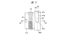
- FIG. 3 is a plan view showing the base case 11b shown in FIG. 4 is a sectional view taken along line AA in FIG. 3,
- FIG. 5 is a sectional view taken along line BB in FIG. 4, and
- FIG. 6 is a sectional view taken along line CC in FIG.
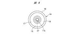
- FIG. 7 is a plan view of the rotating cylinder 14 shown in FIG. 8 is a sectional view taken along line DD in FIG. 7,
- FIG. 9 is a right side view of FIG. 7, and
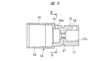
- FIG. 10 is a sectional view taken along line EE in FIG.
- a communication hole 41 is provided at the distal end of the base case 11 b, and the communication hole 41 communicates with the base end of the liquid passage 34.
- the orifice 42 is provided in the rotation operation unit 15, and the orifice 42 communicates with the base end portion of the liquid passage 34 through the communication hole 41.
- the orifice 42 is formed by four through holes 42a to 42d as shown in FIGS.
- the four through holes 42a to 42d are provided in the cylindrical portion 17 of the rotation operation portion 15 at a predetermined interval in the circumferential direction, and penetrate the cylindrical portion 17 in the radial direction.
- any one of the four through holes 42 a to 42 d is located at the same circumferential position as the communication hole 41 and communicates with the communication hole 41. Since the inner diameters of the through holes 42a to 42d are different, the opening degree of communication between the rear chamber 35b and the liquid passage 34 differs depending on the position of the rotation operation unit 15 in the rotation direction.
- the inner diameter of the through hole 42a is the largest, and the inner diameter is gradually reduced from the through hole 42a toward the through hole 42d.
- the communication opening degree of the orifice 42 is maximized.
- the communication opening degree of the orifice 42 is minimized.
- the communication opening degree of the orifice 42 is smaller than the through hole 42a and larger than the through hole 42d.
- the angle ⁇ formed by the central axis of the through hole 42 a and the central axis of the through hole 42 d is about 90 degrees, and the orifice 42 is provided in the range of the rotational angle ⁇ of the rotational operation unit 15. ing.
- a guide hole 43 is formed in the base case 11b of the case 11 so as to extend in the circumferential direction.
- the guide hole 43 has a front circumferential surface 44, a rear circumferential surface 45, and circumferential end surfaces 46 a and 46 b of the case 11, and the rear circumferential surface 45 faces the front end portion of the case 11.
- the front circumferential surface 44 faces the rear end of the case 11.
- Four positioning recesses 47a to 47d are provided on the rear circumferential surface 45 at intervals in the circumferential direction.
- the operation plug 51 is provided in the opening hole 17 a of the cylindrical portion 17 of the rotation operation portion 15.
- An attachment hole 52 is provided in the cylindrical portion 17 of the rotation operation portion 15, and a screw portion 53 a of the positioning pin 53 is screwed to the operation plug 51.
- the positioning pin 53 is fitted into the mounting hole 52, the operation plug 51 is integrated with the rotation operation unit 15, that is, the rotation cylinder 14.
- the rotational direction position of the rotational operation unit 15 is positioned by a positioning pin 53 and positioning recesses 47a to 47d as positioning adjusting means.
- the positioning adjustment means is constituted by positioning pins 53 and positioning recesses 47a to 47d.
- the positioning pin 53 is inserted into the guide hole 43.
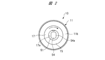
- the protrusion 54 is provided integrally with the operation plug 51, and the protrusion 54 protrudes from the base end surface of the case 11. As shown in FIG. 2, the protrusion 54 has a two-surface width 54 a that is flat with respect to each other, and a rotating operation tool such as a spanner can be adjusted to the two-surface width 54 a of the protrusion 54 as necessary.
- the operation plug 51 is attached and rotated.
- the step surface 19 of the rotating cylinder 14 is pressed against the stopper surface 20 by the spring force of the compression coil spring 37.
- a turning operation tool such as a spanner is hung on the two-surface width 54a, the projection 54 is turned, and the operation plug 51 is turned.
- the positioning of the positioning pin 53 and the positioning recess 47a is released, and the positioning pin 53 rides on the rear circumferential surface 45 between the positioning recess 47a and the positioning recess 47b.
- FIG. 11B the rotating cylinder 14 moves in the axial direction toward the front of the case 11.
- the positioning pin 53 When the operation plug 51 is further rotated by the rotation operation tool, the positioning pin 53 is positioned at the position of the positioning recess 47 b by the spring force of the compression coil spring 37. In this way, the positioning pin 53 is positioned from the positioning recess 47a to an arbitrary position of the positioning recess 47d.
- the through hole 42a of the orifice 42 is in communication with the communication hole 41.
- the through hole 42b communicates with the communication hole 41.
- the through hole 42 c is in communication with the communication hole 41.
- the through hole 42d is in communication with the communication hole 41.
- the positions of the mounting holes 52 and the bottom surfaces of the positioning recesses are set so that the positioning pins 53 are not in close contact with the bottom surfaces of the positioning recesses and a gap is formed between the positioning pins 53 and the bottom surface.
- the shock absorber absorbs an impact
- the pressure of the liquid rises and an impact toward the base end is applied to the rotating cylinder 14.
- the piston 32 moves backward
- the compression coil spring 37 is further compressed by the piston, and a force toward the proximal end portion is further applied to the rotating cylinder 14.
- Such an impact or force in the base end direction applied to the rotating cylinder 14 is transmitted from the step surface 19 of the rotating cylinder 14 to the base case 11b.
- the positioning pins 53 and the bottom surfaces of the positioning recesses are protected, and the positioning pins 53 and the bottom surfaces of the positioning recesses are not damaged or damaged. That is, since the step surface 19 and the stopper surface 20 of the rotating cylinder 14 are in contact with each other, an impact or force applied to the rotating cylinder 14 is transmitted from the rotating cylinder 14 to the case 11 and transmitted to other members. There is nothing. Thereby, the durability of the shock absorber is improved.
- FIG. 1 shows a state where the through hole 42 a of the orifice 42 communicates with the liquid passage 34 via the communication hole 41.
- the hydraulic oil in the rear chamber 35b passes through the gap 36 and flows into the front chamber 35a, and is liquid via the through hole 42a and the communication hole 41. It flows into the rear end of the passage 34 and flows into the front chamber 35a.
- the gap 36 gradually becomes narrower, and the flow resistance of the hydraulic oil flowing through the gap 36 is increased. In this manner, the hydraulic oil flows into the front chamber 35a while receiving passage resistance by the gap 36 and the orifice 42.
- the hydraulic fluid that has flowed into the front chamber 35a flows into the accumulator chamber 39 from the communication passage 24a, and the accumulator 40 contracts. Therefore, oil passing resistance is applied as a drag to the piston 32 that moves backward, and the kinetic energy of the moving member is absorbed by the drag of the oil, that is, the hydraulic oil, and the impact force applied to the moving member is alleviated.
- Rotating the rotating cylinder 14 and selecting one of the plurality of through holes 42a to 42d adjusts the drag characteristic, that is, the buffer characteristic due to the passage resistance of the hydraulic oil.
- the drag characteristic is set to be the largest.
- a positioning pin 53 is provided on the axial extension of the through hole 42 a, and the through hole 42 d with the smallest inner diameter from the position where the largest inner diameter through hole 42 a faces the communication hole 41.
- the rotating cylinder 14 is rotated to a position facing the communication hole 41, the rotating cylinder 14 is rotated clockwise as indicated by an arrow in FIG.
- the state is switched from the state in which the through hole 42 a having the maximum inner diameter communicates with the communication hole 41 to the state in which the through hole 42 d having the minimum inner diameter communicates with the communication hole 41.
- the through hole 42d with the smallest inner diameter is provided at the position of the through hole 42a in FIG. 10
- the through hole 42a with the largest inner diameter is provided at the position of the through hole 42d in FIG. 10, and further on the axial extension of the through hole 42d.
- the positioning pin 53 when the rotation cylinder 14 is rotated clockwise in FIG. 2, the through hole 42 a having the maximum inner diameter is connected to the communication hole 41 from the state in which the through hole 42 d having the minimum inner diameter communicates with the communication hole 41. 41 is switched to a state communicating with 41.
- the rotation operation tool When adjusting the drag characteristics of the hydraulic oil according to the location where the shock absorber 10 is used, as described above, the rotation operation tool is hung on the two-surface width 54a, and the projection 54 is rotated. The rotating cylinder 14 is rotated. As a result, the positioning pin 53 is positioned in any one of the four positioning recesses 47a to 47d, and the drag characteristic can be switched to any of, for example, four stages.
- the step surface 19 of the rotating cylinder 14 abuts against the stopper surface 20 by the spring force of the compression coil spring 37, and the positioning pin 53 is set.
- the positioning recess is fixed. Since a spring force is applied to the rotating cylinder 14, the communication between the orifice 42 and the communication hole 41 is maintained without rotating the rotating cylinder 14.
- the opening degree of the orifice 42 can be changed by the turning operation of the turning cylinder 14, the shock absorber 10 can be easily adjusted in the buffer characteristics, and the shock absorber 10 having excellent operability can be obtained. can get.
- a male screw 50 is provided on the outer peripheral surface of the main case 11a.
- the shock absorber 10 can be mounted on a mounting member (not shown), and the shock absorber 10 can be mounted on the mounting member by a nut screwed to the male screw 50.
- the base end of the case 11 may be shielded by an external member. Even in this case, when the rotating cylinder 14 is rotated, the click feeling when the positioning pin 53 gets over the rear circumferential surface 45 between the positioning recesses 47a to 47d is transmitted to the operator's hand. It is possible to sense which positioning recess the positioning pin 53 is in. Thereby, it is possible to easily adjust the buffer characteristic without visually observing the positioning pin 53 from the outside.
- the orifice 42 may be formed by .about.42c. In that form, when the positioning pin 53 is set in the positioning recess 47d, the hydraulic oil in the rear chamber 35b flows into the front chamber 35a only through the gap 36.
- the number of through holes forming the orifice 42 is not limited to the number described above, and can be an arbitrary number. Further, the angle with respect to the center from the through hole 42a to the through hole 42d is not limited to about 90 degrees as shown in FIG. 6, and may be an arbitrary angle.
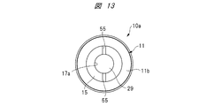
- FIG. 12 is a longitudinal sectional view showing a shock absorber 10a according to another embodiment
- FIG. 13 is a right side view of FIG.
- the operation plug 51 shown in FIG. 1 is not provided in the cylindrical portion 17 of the rotation operation portion 15, and the positioning pin 53 is provided with a screw portion 53a that is screwed to the operation plug 51. It is not done.
- the positioning pin 53 is fixed to an attachment hole 52 provided in the cylindrical portion 17 of the rotation operation portion 15, protrudes radially outward from the cylindrical portion 17, and enters the guide hole 43.
- the shape of the guide hole 43 is the same as that of the shock absorber 10 shown in FIG.
- the rotation direction position of the rotation operation unit 15 is positioned by the positioning pin 53 and the positioning recesses 47a to 47d as positioning adjusting means.
- the positioning adjustment means is constituted by positioning pins 53 and positioning recesses 47a to 47d.
- a slit 55 is provided on the rear end surface of the rotation operation unit 15 in order to mount the rotation operation tool on the rotation operation unit 15 of the rotation cylinder 14.
- the turning cylinder 14 can be turned by mounting a turning operation tool (not shown) having a convex portion that fits into the slit 55.
- the structure for mounting the rotation operation tool on the rotation operation unit 15 may be a convex structure provided with the protrusions 54 as shown in FIG. 1, and as shown in FIG.
- a recess structure provided with a slit 55 may be used.
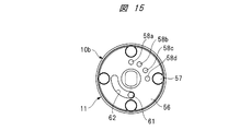
- FIG. 14 is a longitudinal sectional view showing a shock absorber 10b according to still another embodiment
- FIG. 15 is a right side view of FIG.
- the operation plug 51 is abutted against the base end surface of the rotation operation unit 15, and the positioning pin 53 is attached to the rotation operation unit 15.
- the positioning pin 53 protrudes from the operation plug 51 in the axial direction.
- An annular end wall member 56 is fixed to the base end surface of the base case 11 b by a screw member 57, and engagement holes 58 a to 58 d are provided in the end wall member 56.
- the positioning recesses 47a to 47d are formed at the inner ends of the engagement holes 58a to 58d, respectively.
- FIG. 14 shows a state in which the positioning pin 53 is set at the position of the positioning recess 47a.
- the rotational direction position of the rotational operation unit 15 is positioned by the positioning pin 53 and the positioning recesses 47a to 47d as positioning adjusting means.
- the positioning adjustment means is constituted by positioning pins 53 and positioning recesses 47a to 47d.
- a gap is formed between the rotation operation unit 15 and the bottom surface of the operation plug 51 without being in close contact with each other.
- the shock absorber absorbs an impact
- the pressure of the liquid rises and an impact toward the base end is applied to the rotating cylinder 14.
- the compression coil spring 37 is further compressed by the piston 32, a force toward the proximal end portion is further applied to the rotating cylinder 14.
- Such an impact or force in the base end direction applied to the rotating cylinder 14 is transmitted from the step surface 19 of the rotating cylinder 14 to the base case 11b.
- the impact or force in the proximal direction applied to the rotation cylinder 14 is applied to the positioning pin 53 or the bottom surface of the positioning recess.
- the positioning pins 53 and the bottom surfaces of the positioning recesses are protected, and the positioning pins 53 and the bottom surfaces of the positioning recesses are not damaged or damaged. That is, since the step surface 19 and the stopper surface 20 of the rotating cylinder 14 are in contact with each other, an impact or force applied to the rotating cylinder 14 is transmitted from the rotating cylinder 14 to the case 11 and transmitted to other members. There is nothing. Thereby, the durability of the shock absorber is improved.
- the place where the gap is formed is not limited to between the rotation operation unit 15 and the operation plug 51. For example, a gap may be formed between the operation plug 51 and the end wall member 56.
- a guide pin 61 as a guide protrusion is provided at the base end of the rotation operation unit 15, and the guide pin 61 protrudes in the axial direction and penetrates the operation plug 51.
- An arcuate rotation restriction hole 62 extending in the circumferential direction is provided in the end wall member 56, and the guide pin 61 is inserted into the rotation restriction hole 62.
- the rotation range of the rotation cylinder 14 is restricted.
- the rotation range of the rotation cylinder 14 is defined by the positioning pin 53 coming into contact with the end of the guide hole 43, whereas in FIG.
- the rotation range of the rotation cylinder 14 is restricted by the contact between the guide pin 61 and the end face of the rotation restriction hole 62.
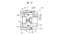
- FIG. 16 is a sectional view showing a part of a shock absorber 10c according to another embodiment, which is a modified example of the shock absorber 10a shown in FIG.
- a guide hole 43 is provided in the cylindrical portion 17 of the rotation operation portion 15.
- a positioning pin 53 is attached to the proximal end portion of the cylindrical portion 17 so as to protrude radially inward, and the positioning pin 53 enters the guide hole 43.
- the positioning concave portions 47a to 47d described above are provided on the front circumferential surface 44 of the guide hole 43.
- FIG. 16 shows a state in which the positioning pin 53 is positioned in the positioning recess 47a.
- the positioning pin 53 when the rotating cylinder 14 is rotated, the positioning pin 53 is unpositioned from the positioning recess 47a and rides on the front circumferential surface 44 between the positioning recess 47a and the positioning recess 47b. .
- the positioning pin 53 is positioned in the positioning recess 47 b by the spring force of the compression coil spring 37. In this way, the positions of the through holes 42a to 42d communicating with the communication hole 41 can be switched.
- the guide hole 43 can be provided in the cylindrical portion 17 even in the configuration in which the operation plug 51 is provided in the cylindrical portion 17 of the rotation operation portion 15.
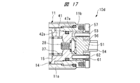
- FIG. 17 is a cross-sectional view showing a part of a shock absorber 10d according to another embodiment, which is a modified example of the shock absorber 10b shown in FIG.
- the positioning pin 53 is attached to the end wall member 56, and the positioning pin 53 protrudes inward toward the base end portion of the rotation operation unit 15.
- Positioning recesses 47a to 47d each having an opening of a bottomed hole are provided at the base end of the rotation operation unit 15.
- the shock absorber 10 d shown in FIG. 17 is also formed with a gap between the rotation operation unit 15 and the operation plug 51.
- the place where the gap is formed is not limited to between the rotation operation unit 15 and the operation plug 51.
- a gap may be formed between the operation plug 51 and the end wall member 56.
- the positioning pin 53 is provided in the rotation operation unit 15, and a plurality of positioning recesses 47a to 47d are provided in the case 11.
- the positioning pin 53 is provided in the case 11, and the plurality of positioning recesses 47 a to 47 d are provided in the rotation operation unit 15. In this way, a plurality of positioning recesses can be provided in either one of the rotation operation unit 15 and the case 11, and the positioning pin 53 can be provided in either one of the rotation operation unit 15 and the case 11.
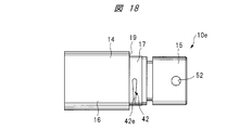
- FIG. 18 is a plan view showing a rotating cylinder of a shock absorber 10e according to another embodiment.
- the orifice 42 provided in the rotation operation unit 15 of the rotation cylinder 14 is formed by a tapered groove 42e that extends along the circumferential direction and whose groove width changes according to the position in the circumferential direction.
- the communication opening degree of the orifice 42 with respect to the communication hole 41 is continuously changed by rotating the rotating cylinder 14.
- any one of the continuously changing communication openings can be selected stepwise.
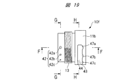
- FIG. 19 is a plan view showing a base case 11b of a shock absorber 10f according to another embodiment.
- 20 is a sectional view taken along line FF in FIG. 19
- FIG. 21 is a sectional view taken along line GG in FIG. 19
- FIG. 22 is a sectional view taken along line HH in FIG.
- FIG. 23 is a plan view of the rotating cylinder 14 to which the base case 11b shown in FIG. 19 is assembled.
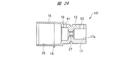
- 24 is a cross-sectional view taken along the line II in FIG.
- the orifice 42 is provided in the rotating cylinder 14, and the communication hole 41 is provided in the base case 11b. That is, the inner diameters of the plurality of through holes are different from each other, and the plurality of through holes are provided at intervals in the rotation direction of the rotation operation unit 15, thereby forming the orifice 42.
- the orifice 42 is provided in the base case 11b, and the communication hole 41 is provided in the rotating cylinder 14. That is, the inner diameters of the plurality of through holes are different from each other, and the plurality of through holes are provided at intervals in the circumferential direction of the base case 11b, whereby the orifice 42 is formed. Even in such a configuration, the communication opening degree can be adjusted by rotating the rotating cylinder 14. Therefore, the orifice 42 can be provided in one of the rotating cylinder 14 and the base case 11b, and the communication hole 41 can be provided in either one.
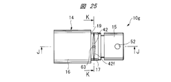
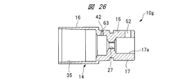
- FIG. 25 is a plan view showing a rotating cylinder 14 of a shock absorber 10g according to another embodiment. 26 is a sectional view taken along line JJ in FIG. 25, and FIG. 27 is a sectional view taken along line KK in FIG.
- the rotary cylinder 14 is provided with an orifice 42.
- the orifice 42 has a through hole 63 that penetrates the cylindrical portion 17, and a taper groove 42 f is provided in the circumferential direction around the through hole 63.
- the tapered groove 42f has a depth that gradually decreases in the circumferential direction around the through hole 63.
- the taper groove 42 f has a width that gradually decreases in the circumferential direction around the through hole 63. Even in the orifice 42 having such a shape, the communication opening degree can be adjusted by rotating the rotating cylinder 14.
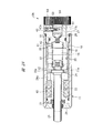
- FIG. 28 is a longitudinal sectional view showing a shock absorber 10h according to another embodiment.
- an operation dial 64 is provided on the operation plug 51, and the operation dial 64 has a knurled outer peripheral surface and protrudes outward from the base end portion of the case 11.
- the operation dial 64 corresponds to the protrusion 54 of the operation plug 51 shown in FIG. Thereby, the operator can rotate the rotation cylinder 14 directly by hand, without using a rotation operation tool like a spanner.
- the opening degree of communication between the rear chamber 35b in the cylinder hole 35 and the liquid passage 34 is changed by rotating the rotating cylinder 14 mounted in the case 11. It is possible to easily adjust the buffer characteristics of the shock absorbers 10 to 10h, and the operability of the shock absorber can be improved. Further, a shock absorber is used for the spring force for maintaining the positioning pin 53 positioned in the positioning recesses 47a to 47d and the spring force for generating a click feeling when the rotating cylinder 14 is rotated.
- the spring force of the compression coil spring 37 that is indispensable for constituting the above is utilized. In this way, by utilizing the spring force of the compression coil spring 37, the number of parts is reduced, and a shock absorber with few failures and high reliability is configured.
- This shock absorber is used for stopping a moving member without giving an impact force to the moving member such as a workpiece in a production line for mass-produced products.
Landscapes
- Engineering & Computer Science (AREA)
- General Engineering & Computer Science (AREA)
- Mechanical Engineering (AREA)
- Fluid-Damping Devices (AREA)
Abstract
L'invention concerne un amortisseur 10 ayant un boîtier 11, dans lequel une tige de piston 25 est montée de façon à se déplacer librement selon un mouvement alternatif dans la direction axiale, et un cylindre rotatif 14 est mis en œuvre à l'intérieur du boîtier 11 de manière à pouvoir tourner librement et se déplacer librement dans la direction axiale. L'alésage de cylindre 35 est divisé en une chambre avant 35a et une chambre arrière 35b par un piston 32 mis en œuvre dans la tige de piston 25. Une force de rappel dans la direction de projection de la tige de piston 25 est appliquée par un ressort hélicoïdal de compression 37. Un orifice 42, dont l'ouverture de communication avec un passage de liquide 34 change en fonction d'une position dans la direction de la rotation, est mis en œuvre dans une partie fonctionnelle de rotation 15. De multiples évidements de positionnement sont prévus dans le boîtier 11 selon des intervalles dans la direction circonférentielle.
Priority Applications (1)
| Application Number | Priority Date | Filing Date | Title |
|---|---|---|---|
| US15/746,566 US10288142B2 (en) | 2015-07-24 | 2016-01-05 | Shock absorber |
Applications Claiming Priority (2)
| Application Number | Priority Date | Filing Date | Title |
|---|---|---|---|
| JP2015-146365 | 2015-07-24 | ||
| JP2015146365A JP6388567B2 (ja) | 2015-07-24 | 2015-07-24 | ショックアブソーバ |
Publications (1)
| Publication Number | Publication Date |
|---|---|
| WO2017017968A1 true WO2017017968A1 (fr) | 2017-02-02 |
Family
ID=57884483
Family Applications (1)
| Application Number | Title | Priority Date | Filing Date |
|---|---|---|---|
| PCT/JP2016/050099 Ceased WO2017017968A1 (fr) | 2015-07-24 | 2016-01-05 | Amortisseur |
Country Status (3)
| Country | Link |
|---|---|
| US (1) | US10288142B2 (fr) |
| JP (1) | JP6388567B2 (fr) |
| WO (1) | WO2017017968A1 (fr) |
Families Citing this family (2)
| Publication number | Priority date | Publication date | Assignee | Title |
|---|---|---|---|---|
| DE102017010876B4 (de) * | 2017-11-24 | 2023-06-01 | Günther Zimmer | Zylinder-Kolben-Einheit mit lastabhängiger Drossel |
| US11255399B2 (en) * | 2018-03-14 | 2022-02-22 | Zf Friedrichshafen Ag | Damping valve for a vibration damper |
Citations (3)
| Publication number | Priority date | Publication date | Assignee | Title |
|---|---|---|---|---|
| JPS6449710U (fr) * | 1987-09-24 | 1989-03-28 | ||
| JPH0637641U (ja) * | 1992-10-23 | 1994-05-20 | 太陽鉄工株式会社 | 流体圧式緩衝装置 |
| JPH07103279A (ja) * | 1993-09-30 | 1995-04-18 | Tokico Ltd | 減衰力調整式油圧緩衝器 |
Family Cites Families (9)
| Publication number | Priority date | Publication date | Assignee | Title |
|---|---|---|---|---|
| US3344894A (en) * | 1965-10-14 | 1967-10-03 | Rex Chainbelt Inc | Adjustable hydraulic shock absorber |
| US3510117A (en) * | 1967-03-22 | 1970-05-05 | Horold W Scholin | Adjustable hydraulic buffering device |
| US3840097A (en) * | 1973-01-22 | 1974-10-08 | Hennells W Co Inc | Adjustable shock absorber |
| JPS6131558Y2 (fr) * | 1981-04-10 | 1986-09-13 | ||
| JPH06346938A (ja) | 1993-06-08 | 1994-12-20 | Ckd Corp | 油圧緩衝器 |
| US5598904A (en) * | 1995-06-05 | 1997-02-04 | Enidine, Inc. | Adjustable energy absorption device |
| FR2806770B1 (fr) * | 2000-03-24 | 2002-08-23 | Jean Perret Ets | Amortisseur hydraulique avec reglage du type d'amortissement |
| FR2902850B1 (fr) * | 2006-06-21 | 2012-04-27 | Soben | Dispositif a butee hydraulique, notamment pour amortisseur reglable |
| JP6259722B2 (ja) * | 2014-06-17 | 2018-01-10 | 株式会社コガネイ | ショックアブソーバ |
-
2015
- 2015-07-24 JP JP2015146365A patent/JP6388567B2/ja active Active
-
2016
- 2016-01-05 WO PCT/JP2016/050099 patent/WO2017017968A1/fr not_active Ceased
- 2016-01-05 US US15/746,566 patent/US10288142B2/en active Active
Patent Citations (3)
| Publication number | Priority date | Publication date | Assignee | Title |
|---|---|---|---|---|
| JPS6449710U (fr) * | 1987-09-24 | 1989-03-28 | ||
| JPH0637641U (ja) * | 1992-10-23 | 1994-05-20 | 太陽鉄工株式会社 | 流体圧式緩衝装置 |
| JPH07103279A (ja) * | 1993-09-30 | 1995-04-18 | Tokico Ltd | 減衰力調整式油圧緩衝器 |
Also Published As
| Publication number | Publication date |
|---|---|
| US20180216691A1 (en) | 2018-08-02 |
| JP6388567B2 (ja) | 2018-09-12 |
| JP2017026070A (ja) | 2017-02-02 |
| US10288142B2 (en) | 2019-05-14 |
Similar Documents
| Publication | Publication Date | Title |
|---|---|---|
| US11761509B2 (en) | Damping force generating mechanism and pressure shock absorber | |
| JP6259722B2 (ja) | ショックアブソーバ | |
| US10145438B2 (en) | Shock absorber | |
| US9796234B2 (en) | Shock absorber | |
| US10112453B2 (en) | Shock absorber | |
| WO2021260904A1 (fr) | Mécanisme de génération de force d'amortissement et absorbeur de choc de pression | |
| JP6388567B2 (ja) | ショックアブソーバ | |
| KR100877613B1 (ko) | 완충기 | |
| JP2010090935A (ja) | バルブ | |
| US10203013B2 (en) | Shock absorber and damping force generator | |
| JP5559576B2 (ja) | 減衰弁 | |
| US20160290432A1 (en) | High efficiency damper for bicycle suspension | |
| JP6198926B1 (ja) | 油圧緩衝器 | |
| JP5324529B2 (ja) | 減衰バルブ | |
| KR20140080177A (ko) | 완충기 | |
| US12044285B2 (en) | Valve adjustment device and shock absorber | |
| JP2016176543A (ja) | 減衰力発生装置及び緩衝器 | |
| CN117739057A (zh) | 阀门 | |
| JP2009024818A (ja) | ショックアブソーバー | |
| JP2008032098A (ja) | 油圧緩衝器の減衰力調整装置 |
Legal Events
| Date | Code | Title | Description |
|---|---|---|---|
| 121 | Ep: the epo has been informed by wipo that ep was designated in this application |
Ref document number: 16830073 Country of ref document: EP Kind code of ref document: A1 |
|
| WWE | Wipo information: entry into national phase |
Ref document number: 15746566 Country of ref document: US |
|
| NENP | Non-entry into the national phase |
Ref country code: DE |
|
| 122 | Ep: pct application non-entry in european phase |
Ref document number: 16830073 Country of ref document: EP Kind code of ref document: A1 |