WO2017126068A1 - Poche chauffante - Google Patents
Poche chauffante Download PDFInfo
- Publication number
- WO2017126068A1 WO2017126068A1 PCT/JP2016/051638 JP2016051638W WO2017126068A1 WO 2017126068 A1 WO2017126068 A1 WO 2017126068A1 JP 2016051638 W JP2016051638 W JP 2016051638W WO 2017126068 A1 WO2017126068 A1 WO 2017126068A1
- Authority
- WO
- WIPO (PCT)
- Prior art keywords
- sheet
- heating
- bag
- seal
- layer
- Prior art date
- Legal status (The legal status is an assumption and is not a legal conclusion. Google has not performed a legal analysis and makes no representation as to the accuracy of the status listed.)
- Ceased
Links
Images

Classifications
-
- B—PERFORMING OPERATIONS; TRANSPORTING
- B65—CONVEYING; PACKING; STORING; HANDLING THIN OR FILAMENTARY MATERIAL
- B65D—CONTAINERS FOR STORAGE OR TRANSPORT OF ARTICLES OR MATERIALS, e.g. BAGS, BARRELS, BOTTLES, BOXES, CANS, CARTONS, CRATES, DRUMS, JARS, TANKS, HOPPERS, FORWARDING CONTAINERS; ACCESSORIES, CLOSURES, OR FITTINGS THEREFOR; PACKAGING ELEMENTS; PACKAGES
- B65D81/00—Containers, packaging elements, or packages, for contents presenting particular transport or storage problems, or adapted to be used for non-packaging purposes after removal of contents
- B65D81/34—Containers, packaging elements, or packages, for contents presenting particular transport or storage problems, or adapted to be used for non-packaging purposes after removal of contents for packaging foodstuffs or other articles intended to be cooked or heated within the package
- B65D81/3415—Containers, packaging elements, or packages, for contents presenting particular transport or storage problems, or adapted to be used for non-packaging purposes after removal of contents for packaging foodstuffs or other articles intended to be cooked or heated within the package specially adapted to be heated in hot water, e.g. boil pouches
- B65D81/3423—Packages shrinking in hot water, e.g. for boiling hams
-
- B—PERFORMING OPERATIONS; TRANSPORTING
- B65—CONVEYING; PACKING; STORING; HANDLING THIN OR FILAMENTARY MATERIAL
- B65D—CONTAINERS FOR STORAGE OR TRANSPORT OF ARTICLES OR MATERIALS, e.g. BAGS, BARRELS, BOTTLES, BOXES, CANS, CARTONS, CRATES, DRUMS, JARS, TANKS, HOPPERS, FORWARDING CONTAINERS; ACCESSORIES, CLOSURES, OR FITTINGS THEREFOR; PACKAGING ELEMENTS; PACKAGES
- B65D33/00—Details of, or accessories for, sacks or bags
- B65D33/01—Ventilation or drainage of bags
-
- B—PERFORMING OPERATIONS; TRANSPORTING
- B65—CONVEYING; PACKING; STORING; HANDLING THIN OR FILAMENTARY MATERIAL
- B65D—CONTAINERS FOR STORAGE OR TRANSPORT OF ARTICLES OR MATERIALS, e.g. BAGS, BARRELS, BOTTLES, BOXES, CANS, CARTONS, CRATES, DRUMS, JARS, TANKS, HOPPERS, FORWARDING CONTAINERS; ACCESSORIES, CLOSURES, OR FITTINGS THEREFOR; PACKAGING ELEMENTS; PACKAGES
- B65D75/00—Packages comprising articles or materials partially or wholly enclosed in strips, sheets, blanks, tubes or webs of flexible sheet material, e.g. in folded wrappers
- B65D75/26—Articles or materials wholly enclosed in laminated sheets or wrapper blanks
-
- B—PERFORMING OPERATIONS; TRANSPORTING
- B65—CONVEYING; PACKING; STORING; HANDLING THIN OR FILAMENTARY MATERIAL
- B65D—CONTAINERS FOR STORAGE OR TRANSPORT OF ARTICLES OR MATERIALS, e.g. BAGS, BARRELS, BOTTLES, BOXES, CANS, CARTONS, CRATES, DRUMS, JARS, TANKS, HOPPERS, FORWARDING CONTAINERS; ACCESSORIES, CLOSURES, OR FITTINGS THEREFOR; PACKAGING ELEMENTS; PACKAGES
- B65D75/00—Packages comprising articles or materials partially or wholly enclosed in strips, sheets, blanks, tubes or webs of flexible sheet material, e.g. in folded wrappers
- B65D75/28—Articles or materials wholly enclosed in composite wrappers, i.e. wrappers formed by associating or interconnecting two or more sheets or blanks
-
- B—PERFORMING OPERATIONS; TRANSPORTING
- B65—CONVEYING; PACKING; STORING; HANDLING THIN OR FILAMENTARY MATERIAL
- B65D—CONTAINERS FOR STORAGE OR TRANSPORT OF ARTICLES OR MATERIALS, e.g. BAGS, BARRELS, BOTTLES, BOXES, CANS, CARTONS, CRATES, DRUMS, JARS, TANKS, HOPPERS, FORWARDING CONTAINERS; ACCESSORIES, CLOSURES, OR FITTINGS THEREFOR; PACKAGING ELEMENTS; PACKAGES
- B65D77/00—Packages formed by enclosing articles or materials in preformed containers, e.g. boxes, cartons, sacks or bags
- B65D77/22—Details
- B65D77/225—Pressure relief-valves incorporated in a container wall, e.g. valves comprising at least one elastic element
-
- B—PERFORMING OPERATIONS; TRANSPORTING
- B65—CONVEYING; PACKING; STORING; HANDLING THIN OR FILAMENTARY MATERIAL
- B65D—CONTAINERS FOR STORAGE OR TRANSPORT OF ARTICLES OR MATERIALS, e.g. BAGS, BARRELS, BOTTLES, BOXES, CANS, CARTONS, CRATES, DRUMS, JARS, TANKS, HOPPERS, FORWARDING CONTAINERS; ACCESSORIES, CLOSURES, OR FITTINGS THEREFOR; PACKAGING ELEMENTS; PACKAGES
- B65D81/00—Containers, packaging elements, or packages, for contents presenting particular transport or storage problems, or adapted to be used for non-packaging purposes after removal of contents
- B65D81/34—Containers, packaging elements, or packages, for contents presenting particular transport or storage problems, or adapted to be used for non-packaging purposes after removal of contents for packaging foodstuffs or other articles intended to be cooked or heated within the package
- B65D81/3415—Containers, packaging elements, or packages, for contents presenting particular transport or storage problems, or adapted to be used for non-packaging purposes after removal of contents for packaging foodstuffs or other articles intended to be cooked or heated within the package specially adapted to be heated in hot water, e.g. boil pouches
-
- B—PERFORMING OPERATIONS; TRANSPORTING
- B65—CONVEYING; PACKING; STORING; HANDLING THIN OR FILAMENTARY MATERIAL
- B65D—CONTAINERS FOR STORAGE OR TRANSPORT OF ARTICLES OR MATERIALS, e.g. BAGS, BARRELS, BOTTLES, BOXES, CANS, CARTONS, CRATES, DRUMS, JARS, TANKS, HOPPERS, FORWARDING CONTAINERS; ACCESSORIES, CLOSURES, OR FITTINGS THEREFOR; PACKAGING ELEMENTS; PACKAGES
- B65D81/00—Containers, packaging elements, or packages, for contents presenting particular transport or storage problems, or adapted to be used for non-packaging purposes after removal of contents
- B65D81/34—Containers, packaging elements, or packages, for contents presenting particular transport or storage problems, or adapted to be used for non-packaging purposes after removal of contents for packaging foodstuffs or other articles intended to be cooked or heated within the package
- B65D81/3446—Containers, packaging elements, or packages, for contents presenting particular transport or storage problems, or adapted to be used for non-packaging purposes after removal of contents for packaging foodstuffs or other articles intended to be cooked or heated within the package specially adapted to be heated by microwaves
- B65D81/3461—Flexible containers, e.g. bags, pouches, envelopes
-
- B—PERFORMING OPERATIONS; TRANSPORTING
- B65—CONVEYING; PACKING; STORING; HANDLING THIN OR FILAMENTARY MATERIAL
- B65D—CONTAINERS FOR STORAGE OR TRANSPORT OF ARTICLES OR MATERIALS, e.g. BAGS, BARRELS, BOTTLES, BOXES, CANS, CARTONS, CRATES, DRUMS, JARS, TANKS, HOPPERS, FORWARDING CONTAINERS; ACCESSORIES, CLOSURES, OR FITTINGS THEREFOR; PACKAGING ELEMENTS; PACKAGES
- B65D2205/00—Venting means
Definitions
- the present invention relates to a heating pouch.
- the microwave oven heating pouches shown in Patent Documents 1 and 2 are safe, convenient, and sanitary packages that can be cooked in a microwave oven in a completely sealed package.
- the greatest feature of the microwave heating pouches of Patent Documents 1 and 2 is an original automatic steaming mechanism.
- the bag is inflated by steam emitted from the heated food.
- steam will be discharged
- This steam port has a safety structure, and there is no danger that the pouch will burst and the contents will scatter.
- Patent Document 1 discloses the following heat treatment package. That is, for the heat treatment in which the same surface sides are brought into contact with each other by a plastic film, a first joint portion is joined in a palm-like shape by heat sealing with a predetermined width, and the contents for heat treatment are hermetically wrapped inside.
- the first joint portion is positioned on the upper surface side of the packaging body during the heat treatment of the contents, and is cut into one side portion from the one end portion toward the center side of the packaging body. It is an easy-open seal that is provided close to and releases the pressure when the internal pressure of the package rises due to heating.
- the peel strength of the easy-open seal is 150 to 1800 g / 15 mm, and when the package body is inflated, the short piece side is made substantially upright by the tension due to the expansion across the first joint, Due to the tension of the film of the packaging body on the opposite long piece side, the first joint portion rises with respect to the upper surface of the packaging body, and one side surface of the first joint portion contacts the short piece side surface of the packaging body Alternatively, proximity is avoided.
- the first joint portion that becomes this palm has an easy-opening property as described above, and is further shifted to one side of the package as described above.
- the upper part is hermetically sealed by heat sealing to complete a heat treatment package suitable for storage and management.
- the package is accommodated in a microwave oven and heated according to a predetermined temperature and time.
- the pressure relief portion provided at the first joint portion peels off and the internal gas is discharged, so that the pressure inside the package is lowered.
- the first joint Since the first joint is attached while being biased to one side in the packaging body, when the packaging body is expanded, the short piece side is made substantially upright by the tension due to expansion across the first joint section, Due to the tension of the package film on the opposite long side, the first joint rises with respect to the upper surface of the package, and contact or proximity between one side of the first joint and the package surface is avoided. Since the passage hole of the relief pressure part is located in the upper part of the package, the content does not leak out from the passage hole. For this reason, the excess pressure that has risen in the package acts at the appropriate position of the first joint having easy-opening properties and causes the internal pressure to escape.
- the plastic film is brought into contact with each other on the same surface side to form a bag by heat sealing, and a palm-shaped steaming junction is provided at one place of these heat seals to form the bag.
- the vapor bonding portion has a high temperature-dependent film interposed between the plastic films.
- the part is an easily openable seal that is located at the upper surface side of the package body and that releases the pressure when the internal pressure of the package body rises due to heating when the contents are heated.
- the openable seal has a peel strength in the normal state of 3 kgf / 15 mm or more, a peel strength at a temperature of 90 degrees Celsius of 0 to 1200 g / 15 mm, and a highly temperature-dependent fill at the vapor-bonded joint.
- a tape inserted between plastic films This tape is composed of a random copolymer polypropylene resin, a random copolymer polypropylene resin 60% by weight, an ethylene- ⁇ -olefin copolymer resin 20% by weight, and a metallocene linear low tape.
- Coextruded film consisting of a blend of 20% by weight density polyethylene, or a random copolymerized polypropylene resin, 60% by weight of a random copolymerized polypropylene resin, 20% by weight of a propylene- ⁇ -olefin copolymer resin, a metallocene linear low density It is a coextruded film composed of a blend of 20% by weight of polyethylene, and the heat-treated packaging body in which the palm-shaped steaming joint is heat-sealed through the tape is shown.
- the contents of the food or the like can be cooked with a microwave oven while being packaged, and the package can be prevented from being ruptured by an internal heating and rising pressure.
- the structure of the package is simple, and it is in bag making or content-filled hermetic packaging, and has a unique effect such as reduced production costs and the ability to provide packaged foods and the like at a low price.
- the inventor of the present application intends to provide a heating pouch suitable for both microwave heating and hot water bathing without further satisfaction with the microwave heating pouch described above.
- the present invention is a bag sheet provided with an easily peelable seal portion as a relief pressure seal portion, and the relief pressure seal portion overlaps a part of the sheet constituting the bag sheet with another part of the sheet.
- the relief pressure seal portion provides a heating pouch that peels off when the internal pressure increases and forms a deaeration passage that connects the inside of the bag sheet and the outside of the bag sheet.
- the relief pressure sealing portion includes an easily peelable layer and a skin layer, and the skin layer covers at least one of the part and the other part of the sheet, and the other one not covered. It is the resin layer which comprises the sealing surface which adhere
- This skin layer uses a material that has a higher tensile yield point stress than the easy peelable layer at high temperatures
- the interlayer peel type uses a material whose interlayer strength with the easy peelable layer decreases at high temperatures. Assume that the seal strength at 100 degrees Celsius is high.
- the above-mentioned “superimposing a part of the sheet on the other part of the sheet” includes not only overlapping the sheets so that they are in direct contact with each other, but also indirectly through other inclusions. For example, including overlapping the two sheets with a tape formed separately from the two sheets sandwiched between the two sheets.
- the skin layer covers at least one of the part of the sheet and the other part means that the skin layer is directly in contact with any of the sheets and is covered with other inclusions.
- a skin layer is provided on the surface of the tape formed separately from the two sheets, and any of the sheets is interposed via the tape.
- skin layers are provided on both surfaces of the tape and the tape is interposed between the two sheets.
- the skin layer on the front side of the tape the skin on the tape and the back side
- One sheet is indirectly coated with the layer as an inclusion
- the skin layer on the back side of the tape is indirectly coated with the other skin as the inclusion with the skin layer on the tape and the surface side.
- the sheet is indirectly covered with the sheet.
- the present invention is a bag sheet provided with an easily peelable seal portion as a relief pressure seal portion, and the relief pressure seal portion is configured such that a part of the sheet constituting the bag sheet is replaced with another part of the sheet.
- the relief pressure seal portion is peeled off when the internal pressure is increased, and forms a deaeration passage that connects the inside of the bag sheet and the outside of the bag sheet.
- the sealing portion provides a heating pouch comprising a flat portion forming a flat sealing surface and a bead portion formed in a protruding shape protruding toward the inner surface side of the bag sheet from the flat portion.
- the present invention has also provided a heating pouch that combines heating by a microwave oven and heating by a hot water bath.
- the present invention is a bag sheet provided with an easily peelable seal portion as a relief pressure seal portion, wherein the relief pressure seal portion overlaps a part of the sheet constituting the bag sheet with another part of the sheet.
- the relief pressure seal part is peeled off when the internal pressure rises to form a deaeration passage that connects the inside of the bag sheet and the outside of the bag sheet, and the relief pressure seal part Comprises at least one of a first seal mechanism and a second seal mechanism, and the relief pressure seal portion has a pressure strength of 6 to 30 kPa at 100 degrees Celsius, and is based on a hot water bath and a microwave oven.
- a heating pouch characterized by being capable of being heated.
- the relief pressure sealing portion includes an easily peelable layer and a skin layer, and the skin layer covers at least one of the part and the other part of the sheet, It is the resin layer which comprises the sealing surface adhere
- the relief pressure sealing portion includes a flat portion forming a flat sealing surface, and a bead portion formed in a protruding shape protruding toward the inner surface side of the bag sheet from the flat portion.
- the bead portion has a pressure strength of 6 to 30 kPa at 100 degrees Celsius, and the bead portion has a pressure strength higher than that of the flat portion.
- the hot water bath includes both hot water baths for cooking and hot water baths for heat sterilization (boil heating).
- the relief pressure sealing portion is provided with an easy-release tape, and the easy-release tape can be implemented as being easier to peel off at room temperature than at room temperature.
- seat can be implemented as what has the said easy peeling layer.
- the tape can be used without using the tape to form the relief pressure sealing portion.
- the present invention is a bag sheet provided with an easily peelable seal part as a relief pressure seal part, and the relief pressure seal part is a part of the sheet constituting the bag sheet.
- the relief pressure seal part peels off when the internal pressure rises and forms a degassing passage that connects the inside of the bag sheet and the outside of the bag sheet.
- a pouch for use with the above-described pressure relief seal portion is provided.
- the pressure-release seal portion has a pressure strength of 6 to 30 kPa at 100 degrees Celsius.
- the relief seal part has a seal strength of 1.3 to 20 N / 15 mm at 100 degrees Celsius.
- the relief pressure seal portion has an initial peak value / intermediate value of 1.3 to 3.0 of the seal strength at 100 degrees Celsius.
- first and second means may be each provided in the relief seal part alone, or may be provided with both of the two means. Further, all of the above first to third means may be provided in the relief pressure sealing portion.
- the present invention can provide a heating pouch in which the skin layer has a thickness of 3 to 40 ⁇ m.
- the microwave oven when heating the microwave oven by the above-described means, it is possible to release water vapor and the like from the degassing passage by peeling off when the internal pressure is increased and reliably forming the degassing passage. Rupture due to an increase in internal pressure can be suppressed.
- the relief seal part in the hot water bath, under the hot water conditions (heating conditions of about 100 degrees Celsius), the relief seal part does not easily peel off due to an increase in internal pressure, and the bag is sealed without forming a degassing passage. Therefore, it is possible to suppress the occurrence of an unfavorable situation in which the contents flow into the hot water.
- the present invention can easily provide a heating pouch suitable for combined use of heating by a microwave oven and hot water bath.
- microwave oven heating it peels off when the internal pressure rises to reliably form a degassing passage to prevent rupture due to the internal pressure rise.
- the necessary pressure-resistant strength can be easily imparted to the relief seal part, and the pressure-resistant strength suitable for the purpose of coexistence of degassing during microwave heating and sealing during hot water is easily achieved. It can be realized.
- the formation of the skin layer facilitates the design of the relief pressure seal portion and leads to the stability of quality. Furthermore, by forming the bead portion together with the flat portion on the relief pressure seal portion, the relief pressure seal portion can be made more difficult to peel off than the flat portion at the bead portion, and the entire relief pressure seal portion can be quickly blown when the internal pressure rises. It provided a structure that prevents peeling and ensures pressure resistance suitable for microwave heating and hot water bathing. More specifically, the present inventor has obtained the knowledge that, as a result of research, the pressure strength at 100 degrees Celsius is 6-30 kPa is suitable for satisfying both microwave heating and hot water bathing. The present invention can provide means for stably and easily obtaining the pressure strength.
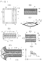
- FIG. 1 is a schematic plan view of a heating pouch according to the present invention
- (B) is a partially cutaway enlarged sectional view of a bag sheet forming the heating pouch of (A)
- (C) is an X- X sectional view
- (D) is an enlarged sectional view of a partly cutaway part of (C)
- (E) is an enlarged sectional view of a partly notched part of (D)
- (F) is an inside of a pouch when heating a microwave oven.
- D The partial cutaway enlarged cross-sectional view showing the state where the relief pressure seal part of (D) is peeled off due to the generation of steam
- (G) is an explanation showing the transition of the peel strength of the heating pouch shown in (A) to (D). Figure.
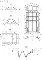
- FIG. 1 is explanatory drawing which shows one process of manufacture of the pouch for heating of FIG. 1 (A)
- B is explanatory drawing which shows the next process of (A)
- C is the next process of (B).
- D is an explanatory view of a mechanism for intermittently feeding a plastic film performed during the steps (A) to (C)
- E is a dimension of each part of one embodiment of the present invention.
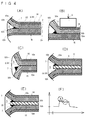
- (A) is explanatory drawing which shows the other manufacturing method of the heating pouch which concerns on this invention
- (B) is a part notch main part which shows other embodiment about the sealing part for relief of the heating pouch which concerns on this invention
- An enlarged cross-sectional view (C) is an enlarged cross-sectional view of an essential part of a notch showing another embodiment of the relief pressure seal portion
- (D) is a view showing still another embodiment of the relief pressure seal portion.
- Partial cutaway enlarged cross-sectional view, (E) is a partially cutaway main portion enlarged cross-sectional view showing another embodiment of the easy peelable tape
- (F) is a partially cutout showing another embodiment of the easy peelable tape.
- the principal part expanded sectional view, (G) is a partially cutaway main part enlarged sectional view showing still another embodiment of the easily peelable tape
- (H) is a partially cutout showing still another embodiment of the easily peelable tape.
- the principal part expanded sectional view, (I) is a partially cutaway principal part enlarged cross section showing still another embodiment of the easy-release tape .
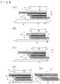
- (A) is a partially cutaway enlarged cross-sectional view showing another embodiment of the relief pressure seal portion
- (B) is a partially cutaway enlarged view showing a method of forming the relief pressure seal portion shown in (A).
- Sectional drawing, (C) is a partially cutaway enlarged cross-sectional view showing a peeled state of the relief pressure seal portion
- (D) is a partially cutaway enlarged view showing another embodiment of the relief pressure seal portion.
- Cross-sectional view, (E) is a partially cutaway enlarged cross-sectional view showing still another embodiment of the relief pressure seal portion
- (F) shows the transition of the peel strength of the relief pressure seal portion shown in (D).
- (A) is a partially cutaway enlarged cross-sectional view showing another example of a method for forming a relief pressure seal portion
- (B), (C), (D), and (E) are portions showing a different formation method from (A).
- the heating pouch which is the heating package according to the present invention
- any one such as a three-side seal, a four-side seal, a joint palm flat bag, a joint palm gusset bag can be selected.
- the heating pouch can be implemented as a bag that automatically fills the contents while making a bag, or a bag sheet that has been made in advance and then filled with the contents to seal the bag sheet.
- FIG. 1 (A) shows a heating pouch 1 in a state where contents are accommodated.
- the heating pouch 1 of this embodiment is a bag sheet 10 provided with an easily peelable seal portion as a relief pressure seal portion 2.
- the relief pressure seal portion 2 is for sealing a portion of the sheet constituting the bag sheet 10 with another portion of the sheet, and the relief pressure seal portion 2 is peeled off when the internal pressure rises due to microwave heating.
- a degassing passage that connects the inside of the heating pouch 1 and the outside of the heating pouch 1 is formed.
- the relief pressure seal portion 2 is for releasing steam, and the relief pressure seal portion 2 is intended to release the pressure in the heating pouch 1 that is the bag sheet 10.
- the bag sheet 10 includes a lower sheet portion 12 and an upper sheet portion 11 that is arranged on the lower sheet portion 12. It is a substantially rectangular shape in plan view that accommodates the food f between the side sheet portion 12 and the upper sheet portion 11.
- the easily peelable relief pressure sealing portion 2 is provided on the upper sheet portion 11. That is, the relief pressure seal portion 2 is formed by laminating a part of the upper sheet part 11 and another part of the upper sheet part 11 in a palm-like shape. The relief pressure seal portion 2 will be described in detail later.
- the heating pouch 1 having a substantially rectangular shape in plan view seals the food f by sealing the lower sheet portion 12 and the upper sheet portion 11 at the front end side 3a, the rear end side 3b, and the left and right end sides 3c and 3d, respectively. .
- the sealing can be performed by heat sealing.
- Each end side of the heating pouch 1 is referred to as a joint portion as necessary in order to distinguish it from the relief pressure seal portion 2 that forms a deaeration passage.
- the front end side 3a after sealing is the front joining portion 3a
- the rear end side 3b after sealing is the rear joining portion 3b
- the right end side 3c after sealing is the right joining portion 3c
- 3d is referred to as a left joint 3d.
- the heating pouch 1 before the food is stored has one of the left and right edges 3c and 3d open, and after the food is stored. The opened edge is sealed as shown in FIGS.
- the upper sheet portion 11 and the lower sheet portion 12 constituting the bag sheet 10 are formed of a single plastic film p.
- the upper sheet part 11 and the lower sheet part 12 are connected to each other from the left and right end sides 3c, 3d before the food is accommodated. That is, taking the uppermost bag sheet in FIG. 2C as an example, the right bag sheet 10 has the left end side 3d open and the right end side 3c closed from the beginning, and the left bag sheet 10 has the right end side. 3c is opened and the left end side 3d is closed from the beginning.
- the bag sheet 10 may be a plastic having heat resistance against heating of a microwave oven.
- the bag sheet 10 includes a base material 10a and a sealant layer 10b.
- the sealant layer 10b is a layer laminated on one surface of the substrate 10a.
- the substrate 10a a plastic material having heat resistance against heating of a microwave oven is used.
- the substrate 10a may be a biaxially stretched film made of polypropylene, polyamide, polyester, ethylene-vinyl alcohol copolymer, vinylidene chloride-acrylate copolymer film, aluminum oxide-deposited biaxially stretched polyester film, polymer, etc. It can be formed of a material such as a taxylylene adipamide-based polyamide stretched film (including a co-extruded laminated film with 6-nylon). However, as long as it has the heat resistance with respect to the heating of a microwave oven, it is also possible to implement by using a plastic material other than the above for the base material 10a.
- the sealant layer 10b is made of a film that is excellent in both sealing strength and mechanical strength, has heat resistance and strength that can withstand heat sterilization and microwave cooking, and has excellent content resistance such as oil resistance.
- Specific examples of such films include linear low-density polyethylene, medium-density / high-density polyethylene, homo-random copolymer / block copolymer polypropylene, ⁇ -olefin copolymer, and others. What is blended and used is mentioned. Further, the sealant layer 10b does not cause peeling due to softening even when heated by microwave oven or hot water bath.
- At least one of the joints 3a to 3d has a notch for opening.
- the notch is a starting point for tearing the bag sheet 1 and may be a notch that facilitates opening.
- the notch may be a V-shaped notch, but may also be a U-shaped notch, for example, or may be a single linear notch.
- the above-described relief pressure sealing portion 2 preferably has a pressure strength at 100 degrees Celsius of 6 to 30 kPa.
- the relief pressure sealing portion 2 thus sets the lower limit value of the pressure strength at 100 degrees Celsius to 6 kPa.
- the lower limit value of the pressure strength is a numerical value for preventing bag breakage under the condition that, in the case of boil sterilization, a water tank of 95 degrees Celsius soaks several tens of centimeters below the water surface.
- the lower limit is preferably set to 8 kPa in order to prevent bag breaking more reliably.
- the relief pressure sealing portion 2 has an upper limit value of the pressure strength at 100 degrees Celsius as 30 kPa.
- This upper limit is a particularly preferable numerical value in order to ensure vapor permeability during heating in the microwave oven. This is because steaming is required due to the internal pressure of water vapor generated from food by microwave heating.
- the relief pressure sealing portion 2 can also be implemented by setting the sealing strength at 100 degrees Celsius to 1.3 to 20 N / 15 mm from the viewpoint of sealing strength. Further, the relief pressure sealing portion 2 can be implemented by setting the initial peak value / intermediate value of the seal strength at 100 degrees Celsius to 1.3 to 3.0 from the viewpoint of the ratio of the initial peak value / intermediate value. . Although the above numerical range is most desirable, it may be slightly deviated from the above ranges of strengths and ratios as long as both microwave heating and hot water bath can be achieved.
- the relief pressure seal portion 2 of this embodiment will be further specifically described. As shown in FIGS. 1A and 1D, the relief pressure sealing portion 2 includes a first sealing mechanism 21 and a steam port 8.
- the first seal mechanism 21 includes an easily peelable tape 20.
- the easily peelable tape 20 includes a tape body 4 that is an easily peelable layer and a skin layer 5.
- the tape body 4 is referred to as an easily peelable layer 4 as necessary.
- the easy-peeling tape 20 is inserted between a part of the upper sheet part 11 and another part of the upper sheet part 11 overlapped with the part at the palm.
- the skin layer 5 is provided on the surface side of the easy-peeling tape 20 that is the upper surface of the easy-peeling tape 20, and forms the seal surface m on the surface side of the easy-peeling tape 20.
- the lower surface of the easy peeling tape 20, that is, the back surface of the tape body 4 is directly bonded to the upper sheet portion 11.
- the skin layer 5 is formed only on one side of the easy-release tape 20.
- the pressure seal strength at 100 degrees Celsius is 6 to 30 kPa as described above, and more preferably.
- the pressure strength at 100 degrees Celsius is 8-25 kPa.
- the skin layer 5 is made of a resin that has a tensile yield stress (JIS K 7161, 7162) of 10-40 MPa, can be heat-sealed, and induces a seal strength of 30 N / 15 mm or more under normal conditions.
- the skin layer 5 can be formed of a polyolefin resin.
- the skin layer 5 is composed of linear low-density polyethylene, medium-density / high-density polyethylene, homo-random copolymer / block copolymer polypropylene, ⁇ -olefin copolymer, etc. alone or blended. Can be used.
- the production method of the skin layer 5 there are methods such as film forming by coextrusion together with other layers, direct application by an extrusion laminating method, and application of a film by a dry laminating method.
- the formation of the skin layer 5 by another known manufacturing method is not excluded.
- Said tape main body 4 is formed with a film with high temperature dependence, and makes an easily peelable layer.
- a material having heat sealability with the sealant layer 10b such as a polyolefin resin such as polypropylene or polyethylene, or a polyester resin can be used.
- the peeling mechanism of the easy peeling layer will be explained.
- the peeling mechanism there are (a) interfacial peeling, (b) delamination, and (c) cohesive peeling. Can be adopted.
- (A) Interfacial peeling is easy peeling at the interface between the bag body (sheet constituting the bag sheet) and the insertion tape (easy peeling tape 20). Therefore, it does not matter if the intermediate layer has the easy peeling layer 4 (no interfacial peeling).
- (B) Delamination is to peel the skin layer 5 and then peel between the skin layer 5 and the easy peel layer 4. The tensile yield stress of the skin layer 5, the skin layer 5 and the easy peel layer The interlayer adhesive strength of 4 affects the peel strength.
- (C) Aggregation peeling means that the material itself of the easy-peeling layer 4 is destroyed, and is produced by adjusting the cohesion force by appropriately providing a dispersed phase in the continuous phase.
- the intermediate layer has the easy peeling layer 4
- the strength when the skin layer 5 is torn off is also affected.
- the resin composition for forming the easy release layer 4 as the cohesive release layer include a blend of polybutene with low density polyethylene.
- the thickness of the skin layer 5 is 3 to 40 ⁇ m, preferably 3 to 30 ⁇ m, more preferably 3 to 15 ⁇ m.
- the thickness of the skin layer 5 is most preferably 5 to 15 ⁇ m.
- the skin layer 5 can be provided on the relief pressure seal portion 2 by inserting the easy-release tape 20 between the folds of the plastic film p before being formed into a palm shape. it can.
- the skin layer 5 is formed by laminating the above-described highly temperature-dependent film, for example, a linear low-density polyethylene material on the tape body 4.
- the skin layer 5 is a polyolefin layer in this example, and the skin layer 5 is a layer formed on the surface of the easily peelable tape 20, that is, the tape body 4 by coextruding the film forming the tape body 4 and the polyolefin. It is.
- the said formation of the skin layer 5 provides the sealing surface m on the surface of the easy peeling tape 20 (tape main body 4) to coat
- the strength of the easily peelable layer having high temperature dependency is reduced by the pressure increase due to heating, and as shown in FIG. 1 (F), the skin layer 5 is torn due to the expansion of the pouch, so that the relief pressure sealing portion 2 is formed. It will be in a state where it peels and can pass through.
- 5a of FIG. 1 (F) has shown the crack of the skin layer 5.
- FIG. 1 (F) has shown the crack of the skin layer 5.
- the easily peelable tape 20 is easily peeled from the bag sheet 10 by the vapor pressure in the bag when heated to a temperature higher than normal temperature, and the required peel strength can be easily adjusted by adjusting the skin layer 5. Can be designed, and the peel strength can be further stabilized.
- the easy-peeling tape 20 on which the skin layer 5 is formed is a tape having a property of reliably peeling when it reaches a predetermined pressure by heating, unlike an easy peel film that can be easily opened manually at room temperature. For this reason, the easy peeling tape 20 can be easily designed to reliably open the bag sheet 1 when the internal pressure rises in microwave heating.
- a known material other than the materials exemplified for the skin layer 5 may be employed.
- the easy-peeling tape 20 may be a multilayer having a layer other than the skin layer 5 together with the skin layer 5. Can be implemented.
- the skin layer 5 peels off from the sealant layer 10b of the bag sheet 10 under pressure.
- the sealing surface m to be bonded is provided.
- the sealant layer 10b of the bag sheet 10 has a thickness of 60 ⁇ m
- the base material 10a is a biaxially stretched polyamide film having a thickness of 15 ⁇ m.
- the tape body 4 has a thickness of 25 ⁇ m and the skin layer 5 has a thickness of 5 ⁇ m.
- the above numerical values are only examples for the thickness of each layer, and any other numerical values can be used as long as the above-mentioned peel strength can be ensured for both microwave heating and hot water bathing.
- the peel strength between the layer of the tape body 4 and the layer of the upper sheet portion 11 is stronger than the peel strength in the skin layer 5.
- the relief pressure seal portion 2 is formed over substantially the entire region in the front-rear width direction between the front end side 3a and the rear end side 3b. Although the entire region in the front-rear width direction may be evenly peeled off, the steam port 8 that peels preferentially in a predetermined position in the front-rear width direction of the relief pressure seal portion 2 over other positions in the front-rear width direction. Is preferably formed. In other words, it is preferable that the steam port 8 is provided as a relief portion when the heating pouch 1 is heated by microwave heating so that the steam is reliably discharged from the steam port 8 to the outside. As shown in FIG.
- the steam port 8 is provided in a portion of the upper sheet portion 11 that covers the easy-peeling tape 20, and the steam port 8 has the front end side 3 a and the rear end of the relief pressure seal portion 2. It arrange
- the steam port 8 is a cutout portion that is cut from the distal end 2 a side of the relief pressure seal portion 2 toward the base side of the relief pressure seal portion 2 (at a depth that does not reach the base portion).
- the steam port 8 is also a non-adhesive part that does not seal the bag sheet 10.
- the relief pressure seal portion 2 rises (in the direction indicated by the arrow Y), and the steam port 8 becomes the uppermost portion of the heating pouch 1 (FIG. 1C).
- the steam does not escape from the steam port 8 at all, but the effect of the skin layer or the bead layer in the relief pressure seal portion 2, that is, the easy-release tape 20 in the direction indicated by the arrow Y in FIG.
- the steam escapes from the steam port 8 in a refreshing manner.
- the easy-peeling tape 20 can be implemented by including the base layer 9 shown in FIG. 3E in addition to the easy-peeling layer 4 and the skin layer 5.
- the base layer 9 uses a resin that has a tensile yield stress (JIS K 7161, 7162) of 10-40 MPa, can be heat-sealed, and induces a seal strength of 30 N / 15 mm or more under normal conditions. Is preferred. That is, the base layer 9 can also be formed of a polyolefin resin.
- the base layer 9 includes linear low-density polyethylene, medium-density / high-density polyethylene, homo-random copolymer, and block copolymer.
- Polymerized polypropylene, ⁇ -olefin copolymer, and the like can be used alone or in combination.
- the base layer 9 can be made into two or more layers, and one of the layers not located on the sealing surface can be a biaxially stretched polyester film, a biaxially stretched polyamide film, a biaxially stretched polypropylene film, an unstretched polypropylene film, or other films.
- a biaxially stretched polyester film a biaxially stretched polyamide film
- a biaxially stretched polypropylene film a biaxially stretched polypropylene film
- unstretched polypropylene film unstretched polypropylene film
- FIGS. 1A to 1D A method for producing the heating pouch shown in FIGS. 1A to 1D will be described in summary. This manufacturing method performs the following steps 1) to 5).
- the belt-shaped plastic film p is formed into a flat-bottomed bag shape that opens upward in the end view, and left and right side edges v, w of the plastic film p at the top of the bag. Fold in a gusset shape so that the side extends laterally to the outside of the bag.
- reference numeral 16 denotes left and right folded portions of the bottom of the gusset.
- the right end side 3c which is the right joint portion 3c
- the left end side 3d which is the left joint portion 3d
- one sheet is used as a gusset bag. It is a fold formed by folding.
- the line for feeding the plastic film p includes a plurality of rollers that move the plastic film p and guide the movement.
- Each roller is depicted as a circle in FIG.
- the dancer roll d can move up and down unlike other rollers whose positions are fixed.
- the plastic film p is continuously fed on the upstream side z1 of the dancer roll d.
- the plastic film p is intermittently fed by the vertical movement of the dancer roll d.
- the steam port 8 is formed by a vertical sealing device (not shown), and the end portion of the steam port seal, that is, the ear portion 13a near the fold line 13 is removed by a slit.
- the side seal portion that is, the left and right joint portions 3c and 3d are formed by heat-sealing the left and right folded portions 16 with a side seal device (not shown).
- a side seal device (not shown)
- the right end side 3c which is the right joint portion 3c
- the left end side 3d which is the left joint portion 3d
- Horizontal sealing step On the downstream side of the dancer roll d, a horizontal sealing device (not shown) is intermittently sealed in a direction intersecting the feeding direction of the plastic film p to form a horizontal seal 3e.
- Horizontal seal cutting step In the horizontal seal 3e, the plastic film p is divided along the horizontal direction by a cutting machine (not shown). By this division, a pair of left and right bag sheets 10 are sequentially formed.
- a microwave oven pouch can be efficiently manufactured with a pair of left and right sides and two horizontal sides.
- the lower sheet portion 12 can be cut to form two symmetrical bag sheets as shown in the uppermost part of FIG.
- a microwave oven pouch can be efficiently manufactured with two horizontal surfaces according to general bag making.
- the use of an easily peelable tape is advantageous in terms of quality stability and cost compared to performing a release agent application or corona treatment as an easy opening process for imparting easy opening to a specific portion of the bag sheet 10. It becomes.
- the dancer roll d is attached to the equipment, the plastic film p can be folded while continuously flowing.
- variation of the folding dimension about a flow direction is suppressed. Further, there is an effect of preventing the folding position from being shifted or the folding from being opened downstream, which leads to prevention of defects, quality stabilization, and reduction of the loss rate. Furthermore, it is possible to prevent the folding position from changing by making the dancer roll d a large-diameter roll having a larger diameter than the other rollers constituting the line, or by providing irregularities on the roll circumference.
- the tape can be inserted into a fixed position without stress by inserting the easily peelable tape at the timing described in the tape insertion process of 2) above. If the insertion is carried out downstream of this, the tape must be moved in the lateral direction by the length of the bag (substantially), resulting in defects such as tape breakage, inversion, and tape damage.
- FIG. 1G the transition of the peel strength of the relief pressure seal portion 2 at the time of heating and pressurization is shown in FIG.
- the vertical axis represents peel strength and the horizontal axis represents time.
- a peak of peel strength appears as an initial value in a portion surrounded by a dot-dash line circle in the graph of FIG. 1 (G), and then the peel strength decreases and changes stably as indicated by an intermediate value surrounded by a dotted circle. is doing. From this, it is possible to secure a large peel strength at the initial stage of pressurization at which the skin portion 5 shown in FIG. 1 (F) is torn, and after the skin layer 5 is torn, the peel strength is lowered and a stable state can be secured. I can grasp that.
- the upper sheet portion 11 and the lower sheet portion 12 constituting the bag sheet 10 are each formed by a single plastic film p.
- the upper sheet portion 11 and the lower sheet portion are separately formed plastic films p, and the right end sides 3c and the left end sides 3d of the plastic film p are sealed. Therefore, the present invention can be implemented as a single unit.
- FIG. 3A shows a state viewed from the same direction as the lowermost drawing in FIG.
- the easy-release tape 20 can also be implemented with a protruding portion h as shown in FIG. 3 (B).
- the protruding portion h is a portion of the easily peelable tape 20 that protrudes toward the inside of the bag of the heating pouch 1, that is, toward the food storage space k.
- the skin layer 5 may be provided on the upper surface side of the tape body 4 or may be provided on the lower surface side of the tape body 4 in both cases where the protruding portion h is provided and not provided. Further, in the embodiment shown in FIGS.
- the easily peelable tape 20 is provided with the skin layer 5 only on one surface, that is, the surface (upper surface) of the easily peelable tape 20 (tape body 4).
- the easy-release tape 20 can be implemented by providing the skin layer 5 on both sides, that is, both the front side and the back side of the tape body 4.
- FIG. 3C shows a state in which the sealing surface of the skin layer 5 on the upper surface side of the tape body 4 is peeled off during heating in the microwave oven. However, when the microwave oven is heated, the sealing surface of the skin layer 5 on the lower surface side of the tape body 4 may be peeled off, or the upper and lower skin layers 5 may be peeled off.
- the sealant layer 10b bonded to the skin layer 5 that does not peel off needs to have a peel strength that does not peel even when water vapor is generated.
- the skin layer 5 that peels from the sealant layer 10b when steam is generated is peeled off the skin layer 5h
- the sealant layer 10b that is bonded to the peeled skin layer 5h is peeled off
- the steam side sealant layer 10h is The skin layer 5 that does not peel from the sealant layer 10b when it is generated.
- the sealant layer 10b that is bonded to the non-peeled skin layer 5n is called a non-peel side sealant layer 10n.
- the bag sheet 10 includes a sheet member (hereinafter referred to as a first sheet member 14) including a base material 10a and a release-side sealant layer 10h, and a sheet member (hereinafter referred to as a second sheet member) including a base material 10a and a non-release-side sealant layer 10n.
- a sheet member hereinafter referred to as a first sheet member 14
- a sheet member hereinafter referred to as a second sheet member
- Each of the sheet members 15) is constituted by a separate sheet member.
- the release-side sealant layer 10h of the first sheet member 14 is already in the conditions and composition shown in the description of FIG. 1D, while the non-release skin layer 5n of the second sheet member 15 is a release skin layer.
- the sealing condition adjusted to the peeling strength that does not peel from the non-peeling side sealant layer 10n (the protruding portion is reduced or eliminated from the opposite-side relief pressure sealing portion 2) Or use adjusted materials. That is, the peel strength may be achieved by both selection of a material constituting the relief pressure sealing portion 2 and adjustment of the sealing condition.
- the relief pressure seal portion 2 is formed between the joining portions of the two bag sheets, and the form of joining these two bag sheets can be variously changed. It is desirable to employ a seal. Most preferably, the embodiment shown in FIG. 5A is advantageous because the sealing condition can be easily adjusted.
- the shape of the palm seal is adopted, and the length of the protruding portion h is set to the non-peeling side (between the upper sheet portion 11 on the upper side u1 and the easy peeling tape 20).
- the length is shorter than the peeling side (between the upper sheet portion 11 on the lower side u2 and the easy peeling tape 20).
- the length of the section where the seal g1 is formed on the non-peeling side is the easy peeling side (lower It becomes longer than the length of the section in which the seal g2 is formed (between the upper sheet portion 11 on the side u2 and the easy peeling tape 20) (in each drawing of FIG. 5, the non-peeling side seal g1 and the easy peeling side). This is an area indicated by dark spots on the seal g2).
- the easy peel side seal g2 is positioned on the lower side (skin layer 5 below the easy peel layer 4), the above structure can be realized very easily.
- the long side and the short side of the protruding portion h can be formed by at least one sealing operation.
- the inner end of the easy-peeling side seal g2 is fixed at the folding position indicated by T in FIG. 5 (A) of the upper sheet portion 11 of the lower u2 folded in half. This is because the inner end of the side seal g1 can be arbitrarily adjusted by simply changing the position of the seal plate S.
- FIG. 5C can be shown.
- the upper sheet portion 11 on the upper side u1 must be once detached so as not to be sealed (see FIG. 5B).
- an easily peelable side seal g2 (the longer side of the protruding portion h) is formed (FIG. 5C).
- FIG. 5A is most advantageous. However, when the present invention is implemented, it is not impossible to implement it as in the other diagrams of FIG.
- the easily peelable tape 20 is provided with the skin layers 5 on both the front and back surfaces, as shown in FIG. 3D, it can also be implemented with the protruding portion h similar to that shown in FIG.
- the thickness of both skin layers 5 is 5 ⁇ m
- the thicknesses of the other layers constituting the bag sheet 10 and the relief pressure seal portion 2 other than the skin layer 5 are as described above. This is the same as each layer in FIG.
- the above numerical values are examples for the thicknesses of the respective layers, and any other numerical values can be used as long as the above-described peel strength that achieves both microwave heating and hot water bath can be secured.
- matters not particularly mentioned are the same as those in the embodiment shown in FIGS.
- FIG. 3 (F) to 3 (I) show still another embodiment of the easy-release tape 20.
- FIG. An easily peelable tape 20 shown in FIG. 3 (F) is composed of the above easily peelable layer 4 and the base layer 9.
- the easy-release tape 20 shown in FIG. 3 (G) includes an easy-release layer 4 on the front surface side and the back surface side (upper and lower surfaces) of the base layer 9, and the skin layer 5 is easily laminated on both the easy-release layers 4.
- the skin layer 5 is the front and back of the release tape 20.
- the easily peelable tape 20 shown in FIG. 3 (H) is composed only of the easily peelable layer 4 and does not include the skin layer 5 or the base layer 9 described above.
- FIGS. 3E to 3I are composed of the base layer 9 and the easily peelable layer 4 laminated on the front side and the back side (upper and lower sides) of the base layer 9.
- the skin layer 5 is not provided.
- items not particularly mentioned are the same as those shown in FIG. 1, FIG. 2, or FIGS. 3A to 3D. .
- the relief pressure sealing portion 2 includes a second sealing mechanism 22 and a steam port 8.
- the steam port 8 is the same as the relief pressure seal portion 2 provided with the first seal mechanism 21 shown in FIG.
- the second sealing mechanism 22 includes a flat portion 6 that forms a flat sealing surface m, and a resin bead portion 7 formed in a protruding shape that protrudes toward the inner surface side of the bag sheet 1 from the flat portion 6.
- the inner surface side of the bag sheet 1 refers to the thickness direction of the sheet member that faces the seal surface m and is bonded to the seal surface m.
- the overall pressure relief seal portion 2 including the flat portion 6 and the bead portion 7 has a pressure resistance of 6 to 30 kPa.
- the bead portion 7 has a higher pressure resistance than the flat portion 6.
- the strength drop at high temperature is significant compared to PE (polyethylene) and PP (polypropylene) with uniform composition at high temperature. It is very difficult to design in the above peel strength range.
- a method of increasing the peel strength only at the initial stage of peeling is adopted, and it is preferable to employ the second seal mechanism 22 including the bead portion 7 as the method.
- the above-mentioned bead portion 7 is a bead of resin provided on the sealant layer 10b at the time of sealing, that is, bulges, by performing sealing at a high temperature or high pressure.
- the second seal mechanism 22 is a position closest to the accommodation space k in the deaeration passage from the accommodation space k side to the steam port 8 formed during steaming, that is, an inflow portion from the bag inside to the deaeration passage.
- the bead part 7 which is the above-mentioned rise is provided in the position which becomes.
- the bead part 7 which is a swelling part is arrange
- the intermediate region on the bag outer side, that is, on the steam port 8 side than the bead portion 7 is the flat portion 6 without the bead portion 7.
- the peel strength of the bead portion 7 at the initial peeling is 1.3 to 3.0 times the peel strength of the flat portion 6.
- the bag sheet 10 is composed of the first sheet member 14 and the second sheet member 15 having different properties of the sealant layer 10b.
- the sealant layer 10b of the first sheet member 14 located above the bead portion 7 serves as a release-side sealant layer 10b and serves as a non-peeling-side sealant layer 10b of the second sheet member 15 located below the bead portion 7. It is directly bonded to the flat portion 6 included in 10b.
- the non-peeling side sealant layer 10b functions in the same manner as the tape body 4 of the above-described easy-peeling tape 20, and when the pouch is expanded by microwave heating, as shown in FIG.
- the sealant layer 10b positioned below the bead portion 7 is used as a release side sealant layer 10b that peels from the bead portion 7, and the sealant layer 10b positioned above the bead portion 7 is used as a bead. It is also possible to implement as a non-peeling side sealant layer 10b that does not peel from the portion 7.
- the bead portion 7 has the sealant layer 10b on both sides of the upper sheet portion 11 that is in direct contact with another portion of the upper sheet portion 11 over the other portion. It can be formed by heating and melting. However, from the lower side of FIG. 4 (B), the lower second sheet portion 15 is heated by the seal bar s from the base material 10a side to melt the lower sealant layer 10b in the figure to form the bead portion 7. It is good. Moreover, it can implement also as what forms the bead part 7 by heat-dissolving both the upper and lower sealant layers 10b.
- a receiving member (not shown) facing the bag sheet may be provided on the opposite side of the seal bar s across the bag sheet.
- the heating may be performed by the seal bar s with the bag member sandwiched by the receiving member together with the seal bar s.
- FIG. 4F shows the transition of the peel strength of the relief pressure seal portion 2 during heating and pressurization.
- the vertical axis represents peel strength and the horizontal axis represents time.
- a peak of peel strength appears as an initial value in a portion surrounded by a dot-dash line circle in the graph of FIG. 4 (F), and then the peel strength decreases and stabilizes as indicated by an intermediate value surrounded by a dotted circle. It has changed. From this, in the second seal mechanism 22 provided with the bead portion 7, a large peel strength at the initial stage of pressurization is secured in the bead portion 7, and a stable one with a constant peel strength can be secured in the flat portion 6. I can understand.
- FIG. 4 (D) the second seal mechanism 22 is separate from the bag sheet 10 and easily peelable as in the embodiment shown in FIG. 1 (D) and FIGS. 3 (B) to 3 (E). 20 can be implemented. That is, in this modified example, the first seal mechanism 21 and the second seal mechanism 22 are provided side by side.
- the easily peelable tape 20 is composed only of the tape body 4 shown in the embodiment shown in FIG. 1 (D) and FIGS. 3 (B) to 3 (D). That is, in the example shown in FIG. 4D, the easy-release tape 20 does not include the skin layer 5.
- the easily peelable tape 20 that is, the surface of the tape body 4 forms a flat surface 6, and a bead portion 7 is provided on the surface of the tape body 4 together with the flat portion 6. Moreover, as shown to FIG.4 (E), it can implement also as what provides the flat part 6 and the bead part 7 in both the surface of the easily peelable tape 20, and a back surface.
- the easily peelable tape 20 can be implemented as including the protruding portion h that protrudes toward the accommodation space k in the examples shown in FIGS.
- the bead portion 7 is arranged not only near the accommodation space k of the heating pouch 1 but also on the opposite side of the accommodation space k across the bead portion 7, that is, on the front end 2 a side of the relief seal portion 2. It can be implemented as an arrangement.
- the relief pressure seal portion 2 can be implemented as including both the first seal mechanism 21 and the second seal mechanism 22. That is, for the easily peelable tape 20, the skin layer 5 is provided on the front surface and the back surface of the tape body 4, and the bead portion 7 is transferred from both skin layers 5 providing the sealing surface m to the bag sheet 10, that is, the upper sheet portion 11. It can protrude toward the inside of the thickness of the upper sheet part 11.
- the first seal mechanism 21 shown in FIGS. 1, 2, and 3A to 3D is provided for matters not particularly mentioned. This is the same as the embodiment, and the description is omitted.
- the first sealing mechanism 21 including the skin layer 5 is configured to form a degassing passage by the skin layer 5 being torn by the internal pressure when the internal pressure is increased by microwave heating.
- the first seal mechanism 21 can easily achieve the desired pressure resistance without greatly biasing the seal strength. Therefore, the first seal mechanism 21 is superior to the second seal mechanism 22 in terms of stability.
- the skin layer 5 is easy to design and leads to stable quality. As described above, the degassing passage is formed by tearing the skin layer 5 when the internal pressure rises due to microwave heating.
- the heating pouch 1 has a lateral width or lateral width t1 of 180 mm, a longitudinal width or longitudinal width t2 of 150 mm, and a left lateral width t3 between the left end and the base end of the relief pressure sealing portion 2 of 150 mm.
- the right lateral width t4 between the base end and the right end of the relief pressure seal portion 2 is 30 mm
- the front-rear width t5 of the front joint portion 3a is 10 mm
- the front-rear width t6 of the rear joint portion 3b is 10 mm.
- the right joint 3c is folded to form the bottom.
- the protrusion width t8 from the proximal end to the distal end of the relief pressure seal portion 2 is 10 mm. After the contents are put in from the position of the left joint 3d, the left joint 3d is formed.
- the lateral width t7 of the left joint 3d is 10 mm.
- Insertion Tape 20 A coextruded film composed of three layers of a base layer 9, an easy peeling layer 4 and a skin layer 5 shown in FIG.
- the easy peeling layer 4 was adjusted to a thickness of 10 ⁇ m
- the skin layer 5 was adjusted to a thickness of 0, 5, 15, 30, 40, and 50 ⁇ m. Note that the total thickness was 110 ⁇ m only for the skin layer of 50 ⁇ m, and the others were 70 ⁇ m, and the base layer 9 was adjusted to have such a thickness.
- prime polymer SP3530 L-LDPE, density 931 kg / cubic meter, tensile yield stress 13 MPa
- the easy release layer 4 was prepared by blending Nippon Polyethylene Novatec LD LF443 (LDPE) and Mitsui Chemicals Tafmer BL3110M (polybutene) in 80/20 (%), respectively.
- test bag heat pouch 1
- ONy 15 ⁇ m Unitika ON-RT
- L-LDPE 50 ⁇ m Toyobo L-6101
- a bag of 150 ⁇ 180 mm was prepared, and each insertion tape was sandwiched and sealed at the steam port.
- the sealing was performed under the conditions of a sealing temperature of 160 ° C., a sealing time of 1 second, a sealing pressure of 0.2 MPa, and a sealing frequency of 2 times.
- Test method 3-1-1) Pressure strength at 100 degrees Celsius According to JIS Z0238 container burst strength test, the test bag is filled with air and sealed, and the air bag is held at 100 degrees Celsius. Then, air was fed into the test bag in an amount of 1.0 L / min, and the pressure when steaming or breaking the bag was measured to obtain the pressure resistance.
- 3-1-2) Seal strength at 100 degrees Celsius In accordance with JIS Z0238 heat seal strength test, the steam port is cut to a width of 15 mm, and in an air bath maintained at 100 degrees Celsius, a tensile speed of 300 mm / min, Seal strength (peak value and intermediate value) was measured under the condition of a peeling angle of 180 degrees.
- Example 4 can be used as the heating pouch of the present invention, it is inferior to the other examples (for this reason, it is marked as “-” in Table 1), and the other examples are compared with Example 4. Suitable as a heating pouch of the present invention.
- Comparative Example 1 does not include the skin layer 5, and the pressure resistance at 100 degrees Celsius is 4.8 kPa, and the seal strength peak value at 100 degrees Celsius is 0.82 N / 15 mm. An intermediate value of seal strength at 100 degrees is set to 0.75 N / 15 mm, and an initial peak value / intermediate value is set to 1.09.
- the thickness of the skin layer 5 is 2 ⁇ m
- the pressure strength at 100 degrees Celsius is 5.3 kPa
- the peak value of the seal strength at 100 degrees Celsius is 1.12 N / 15 mm
- the seal strength at 100 degrees Celsius is 0.78 N / 15 mm
- the initial peak value / intermediate value is 1.44.
- Comparative Example 3 As shown in Table 1, in Comparative Example 3 described above, there was no problem in both boil sterilization suitability and hot water bath suitability, but the microwave oven automatic steaming property was broken and the result was x.
- the bag breaking of Comparative Example 3 occurs after the sheet member 14 is stretched by the internal pressure. This is because, in a situation where the easily peelable layer 4 cannot be easily peeled off, the weakest portions of these are generally destroyed including the seal portions 3a to 3d and the first and second sheet members 14 and 15. It depends.
- Example 5 Details of the test results shown in Table 1 will be described later together with the evaluation of Example 5 shown in Table 2 as the evaluation results of Examples.
- the seal strength in Table 1 is as described in JIS Z 0238: 1998 (Test method for heat-sealed soft packaging bags and semi-rigid containers). The test was conducted according to the heat seal strength test of the bag, and the presence or absence of broken bag was determined according to JIS Z 0238: 1998. The test was performed according to the burst strength test of the container. In addition, the above 7. The correction of the load in the heat seal strength test of the bag conforms to JIS P 8113 (paper and paperboard-tensile property test method-Part 2: constant speed extension method).
- Example 5 shows the test results of Example 5.
- the fifth embodiment is of the type shown in FIG. 4A that employs the second seal mechanism 22 and includes the bead portion 7. Therefore, Example 5 does not include the skin layer 5 unlike Examples 1 to 4 in Table 1.
- Example 5 shown in Table 2 each test method and test bag manufacturing method are the same as those shown in Table 1, and the dimensions and configuration of the heating pouch 1 are the same as those described with reference to FIG. It is.
- Example 5 As shown in Table 2, in Example 5, the size of the bead portion 7, that is, the protruding width protruding from the flat portion 6 that is the seal surface m is 13 ⁇ m, the pressure strength at 100 degrees Celsius is 8.7 kPa, and the degree of pressure is 100 degrees Celsius.
- the peak value of the seal strength is 1.67 N / 15 mm, the intermediate value of the seal strength at 100 degrees Celsius is 0.82 N / 15 mm, and the initial peak value / intermediate value is 2.04.
- Table 2 about the test result of Example 5, as shown in Table 2, there was no bag breaking in any test of microwave oven automatic steaming property, boil sterilization suitability, and hot water bath suitability.
- Example 1 Pressure resistance at 100 ° C.
- Examples 1, 2, 3, and 5 After the test bag was fully inflated into a spherical shape due to the introduction of air, the easy-open seal part peeled off after 3 seconds, and the burst sound The steam was passed normally without leakage of the contents (water). After confirming the easy-open seal part after the test, the skin layer 5 was torn in Examples 1, 2, and 3. In Example 5, the bead part 7 was peeled from the sealant layer 10b of the seal part, and the easy peel layer 4 was Aggregate and peel. It was a normal peeling situation.
- Example 4 As in the case of (1) 1), steaming was normally performed by peeling the easy-peeling layer, but after the swelled into a spherical shape, the time until steaming increased to 5 seconds. We will refer to the evaluation in Table 1 in (2) 2) below.
- Example 4 Although the steaming was normally performed in the same manner as in (2) 1) above, the time until the steaming was increased to 5 seconds after swelling in a spherical shape. For this reason, as described above, it was evaluated as ⁇ ⁇ ( ⁇ minus) in the microwave oven automatic vapor permeability column of Table 1 as being slightly inferior to the other examples.
- the thickness of the skin layer 5 from Comparative Example 2, Examples 1 to 4, and Comparative Example 3 in Table 1 from the viewpoint of boil sterilization suitability and hot water suitability is preferably 4 to 40 ⁇ m from Comparative Example 2 and Examples 1 to 3, and the thickness of the skin layer 5 is particularly preferably 5 to 4 ⁇ m.
- the thickness is preferably 40 ⁇ m, and more preferably 5 to 30 ⁇ m.
- the pressure strength at 100 degrees Celsius is preferably 6 to 40 kPa from Comparative Example 2, Examples 1 to 4 and Comparative Examples 3 in Table 1, and particularly Comparative Example 2 and Examples 1 to 4 to 7 to 28. It is preferably 2 kPa, and particularly preferably from Examples 1 to 3 to 8.6 to 9 kPa.
- the peak value of the seal strength at 100 degrees Celsius is preferably 1.3 to 35 N / 15 mm from Comparative Example 2, Example 1 to 4 and Comparative Example 3 in Table 1, and in particular Comparative Example 2 and Example 1 are used. 4 to 1.3 to 20 N / 15 mm is preferable, and 1.5 to 17.1 N / 15 mm is particularly preferable. Among them, Examples 1 to 3 to 1.62 to 16.4 N / 15 mm are preferable.
- the peak value / intermediate value calculated from the peak and intermediate value of the seal strength at 100 degrees Celsius in Table 1 is preferably set to 1.3 to 3 from Comparative Example 2 and Examples 1 to 4, particularly 1 0.5 to 2.8 is preferable, and Examples 1 to 3 to 1.99 to 2.1 are particularly preferable.
- the pouch for heating which can make a microwave oven and the hot water bath including boiling heating compatible can be provided.
- the bead portion 7 from Table 2 it is possible to take numerical values within the range of each strength and ratio of the seal table 1 as a whole for the relief seal portion 2 and appropriate for boil sterilization suitability, hot water bath suitability, microwave oven heating. It was understood that there was no problem with steaminess.
Landscapes
- Engineering & Computer Science (AREA)
- Mechanical Engineering (AREA)
- Life Sciences & Earth Sciences (AREA)
- Food Science & Technology (AREA)
- Chemical & Material Sciences (AREA)
- Composite Materials (AREA)
- Package Specialized In Special Use (AREA)
- Packages (AREA)
Abstract
Priority Applications (6)
| Application Number | Priority Date | Filing Date | Title |
|---|---|---|---|
| PCT/JP2016/051638 WO2017126068A1 (fr) | 2016-01-21 | 2016-01-21 | Poche chauffante |
| JP2016546856A JP6072997B1 (ja) | 2016-01-21 | 2016-01-21 | 加熱用パウチ |
| KR1020187022816A KR102579018B1 (ko) | 2016-01-21 | 2016-01-21 | 가열용 파우치 |
| US16/071,859 US20190047772A1 (en) | 2016-01-21 | 2016-01-21 | Heating pouch |
| CN201680070263.7A CN108473249B (zh) | 2016-01-21 | 2016-01-21 | 加热用小袋 |
| JP2017008643A JP6916621B2 (ja) | 2016-01-21 | 2017-01-20 | 加熱用パウチ |
Applications Claiming Priority (1)
| Application Number | Priority Date | Filing Date | Title |
|---|---|---|---|
| PCT/JP2016/051638 WO2017126068A1 (fr) | 2016-01-21 | 2016-01-21 | Poche chauffante |
Publications (1)
| Publication Number | Publication Date |
|---|---|
| WO2017126068A1 true WO2017126068A1 (fr) | 2017-07-27 |
Family
ID=57937619
Family Applications (1)
| Application Number | Title | Priority Date | Filing Date |
|---|---|---|---|
| PCT/JP2016/051638 Ceased WO2017126068A1 (fr) | 2016-01-21 | 2016-01-21 | Poche chauffante |
Country Status (5)
| Country | Link |
|---|---|
| US (1) | US20190047772A1 (fr) |
| JP (2) | JP6072997B1 (fr) |
| KR (1) | KR102579018B1 (fr) |
| CN (1) | CN108473249B (fr) |
| WO (1) | WO2017126068A1 (fr) |
Families Citing this family (10)
| Publication number | Priority date | Publication date | Assignee | Title |
|---|---|---|---|---|
| JP7316747B2 (ja) * | 2017-03-30 | 2023-07-28 | 大日本印刷株式会社 | 包装袋およびそれを用いた包装体 |
| JP6922366B2 (ja) | 2017-04-12 | 2021-08-18 | 凸版印刷株式会社 | 通蒸型パウチ |
| JP7599815B2 (ja) * | 2018-01-31 | 2024-12-16 | 大日本印刷株式会社 | 袋 |
| KR20250100782A (ko) * | 2018-05-16 | 2025-07-03 | 이데미쓰 유니테크 가부시키가이샤 | 주머니체 및 주머니체의 제조 방법 |
| JP7290929B2 (ja) * | 2018-05-16 | 2023-06-14 | 出光ユニテック株式会社 | 袋体および袋体の製造方法 |
| JP7157612B2 (ja) * | 2018-10-01 | 2022-10-20 | 株式会社サンエー化研 | 加熱処理包装袋、加熱処理包装袋の製造方法及び電子レンジ用食品 |
| WO2020162424A1 (fr) * | 2019-02-04 | 2020-08-13 | 日清フーズ株式会社 | Sauce conditionnée dans un sachet multiparois |
| JP2021075289A (ja) * | 2019-11-06 | 2021-05-20 | 東洋製罐株式会社 | 電子レンジ用パウチ |
| KR102520105B1 (ko) * | 2021-05-14 | 2023-04-10 | 허은성 | 전자렌지 식품 포장백 |
| KR102686469B1 (ko) * | 2023-08-29 | 2024-07-19 | 농업회사법인주식회사 대화농산 | 내부 압력 배출 성능이 우수한 식품 포장 봉투 |
Citations (4)
| Publication number | Priority date | Publication date | Assignee | Title |
|---|---|---|---|---|
| JP2009529470A (ja) * | 2006-03-10 | 2009-08-20 | グラフィック パッケージング インターナショナル インコーポレイテッド | マイクロ波相互作用ウェブを備える容器 |
| JP2013151317A (ja) * | 2011-12-28 | 2013-08-08 | Kyoraku Co Ltd | 包装袋 |
| JP2013163546A (ja) * | 2012-02-13 | 2013-08-22 | Kyoraku Co Ltd | 包装袋 |
| JP2014012552A (ja) * | 2012-07-05 | 2014-01-23 | Seisan Nipponsha:Kk | 減圧弁付き包装用袋 |
Family Cites Families (8)
| Publication number | Priority date | Publication date | Assignee | Title |
|---|---|---|---|---|
| JPH0431273A (ja) * | 1990-05-14 | 1992-02-03 | Toyo Alum Kk | 食品包装体 |
| JP3035484U (ja) | 1996-09-05 | 1997-03-18 | 株式会社エル | 歯ブラシ |
| JP4150513B2 (ja) * | 2001-04-23 | 2008-09-17 | 株式会社サンエー化研 | 加熱処理用包装体 |
| JP4929550B2 (ja) * | 2001-09-11 | 2012-05-09 | 東洋製罐株式会社 | 電子レンジ用包装袋及び該包装袋内に内容物を充填した包装体の製造方法 |
| AU2004245549A1 (en) * | 2003-06-05 | 2004-12-16 | 3M Innovative Properties Company | Plastic container with rupturable seal |
| AU2005250421A1 (en) * | 2004-05-27 | 2005-12-15 | Perftech Inc. | Packaging material and method for microwave and steam cooking of perishable food product |
| JP4902149B2 (ja) * | 2005-07-25 | 2012-03-21 | 三井化学株式会社 | 容器 |
| EP2157029A1 (fr) * | 2008-08-19 | 2010-02-24 | Amcor Flexibles Transpac N.V. | Procédé pour la production d'un emballage auto-ventilant |
-
2016
- 2016-01-21 WO PCT/JP2016/051638 patent/WO2017126068A1/fr not_active Ceased
- 2016-01-21 CN CN201680070263.7A patent/CN108473249B/zh active Active
- 2016-01-21 US US16/071,859 patent/US20190047772A1/en not_active Abandoned
- 2016-01-21 KR KR1020187022816A patent/KR102579018B1/ko active Active
- 2016-01-21 JP JP2016546856A patent/JP6072997B1/ja active Active
-
2017
- 2017-01-20 JP JP2017008643A patent/JP6916621B2/ja active Active
Patent Citations (4)
| Publication number | Priority date | Publication date | Assignee | Title |
|---|---|---|---|---|
| JP2009529470A (ja) * | 2006-03-10 | 2009-08-20 | グラフィック パッケージング インターナショナル インコーポレイテッド | マイクロ波相互作用ウェブを備える容器 |
| JP2013151317A (ja) * | 2011-12-28 | 2013-08-08 | Kyoraku Co Ltd | 包装袋 |
| JP2013163546A (ja) * | 2012-02-13 | 2013-08-22 | Kyoraku Co Ltd | 包装袋 |
| JP2014012552A (ja) * | 2012-07-05 | 2014-01-23 | Seisan Nipponsha:Kk | 減圧弁付き包装用袋 |
Also Published As
| Publication number | Publication date |
|---|---|
| KR20180103957A (ko) | 2018-09-19 |
| CN108473249B (zh) | 2021-04-27 |
| US20190047772A1 (en) | 2019-02-14 |
| KR102579018B1 (ko) | 2023-09-15 |
| JP6072997B1 (ja) | 2017-02-01 |
| JP2017128391A (ja) | 2017-07-27 |
| JP6916621B2 (ja) | 2021-08-11 |
| JPWO2017126068A1 (ja) | 2018-01-25 |
| CN108473249A (zh) | 2018-08-31 |
Similar Documents
| Publication | Publication Date | Title |
|---|---|---|
| JP6072997B1 (ja) | 加熱用パウチ | |
| JP7375097B2 (ja) | ジッパーテープおよび袋体 | |
| JP5007742B2 (ja) | 易壊性シールを備えた複室パウチ | |
| JP4150513B2 (ja) | 加熱処理用包装体 | |
| JP5887745B2 (ja) | 電子レンジ加熱用容器 | |
| JP4713091B2 (ja) | 電子レンジ加熱用包装袋 | |
| JP6536878B2 (ja) | 多重袋 | |
| JP2005059872A (ja) | 電子レンジ用包装袋 | |
| US20070257030A1 (en) | Microwaveable package | |
| WO2018159509A1 (fr) | Sac multicouche | |
| JP2005324846A (ja) | 電子レンジ加熱用包装袋 | |
| JP2001106270A (ja) | 加熱処理用包装体 | |
| JP2005047598A (ja) | 蒸気抜き機能を有する包装袋とそれを用いた包装体 | |
| JP2005047605A (ja) | 蒸気抜き機能を有する包装袋とそれを用いた包装体 | |
| JP2010126241A (ja) | 積層フィルム、積層テープ及びこれを用いた電子レンジ加熱用包装袋 | |
| JP4086546B2 (ja) | 包装袋および包装体 | |
| JP2005047604A (ja) | 蒸気抜き機能を有する包装袋とそれを用いた包装体 | |
| JP7353029B2 (ja) | 自立型包装袋、スパウト付自立型包装袋、内容物入り自立型包装袋及び内容物入りスパウト付自立型包装袋 | |
| JP2005067642A (ja) | 加熱処理用包装体および食品の加熱処理方法 | |
| JP4997759B2 (ja) | 電子レンジ用包装袋 | |
| US20220289458A1 (en) | Multi-compartment retort package | |
| JP6773995B2 (ja) | 多重袋 | |
| JP7529640B2 (ja) | 包装袋 | |
| JP2008110763A (ja) | 食品包装用フィルムおよびこれを用いた電子レンジ加熱用包装袋 | |
| JP2020100416A (ja) | シート材からなる自立容器 |
Legal Events
| Date | Code | Title | Description |
|---|---|---|---|
| ENP | Entry into the national phase |
Ref document number: 2016546856 Country of ref document: JP Kind code of ref document: A |
|
| 121 | Ep: the epo has been informed by wipo that ep was designated in this application |
Ref document number: 16886310 Country of ref document: EP Kind code of ref document: A1 |
|
| NENP | Non-entry into the national phase |
Ref country code: DE |
|
| ENP | Entry into the national phase |
Ref document number: 20187022816 Country of ref document: KR Kind code of ref document: A |
|
| WWE | Wipo information: entry into national phase |
Ref document number: 1020187022816 Country of ref document: KR |
|
| 122 | Ep: pct application non-entry in european phase |
Ref document number: 16886310 Country of ref document: EP Kind code of ref document: A1 |