WO2017159926A1 - Appareil de fabrication de noyau stratifié de type adhésif et dispositif de stratification de noyau associé - Google Patents
Appareil de fabrication de noyau stratifié de type adhésif et dispositif de stratification de noyau associé Download PDFInfo
- Publication number
- WO2017159926A1 WO2017159926A1 PCT/KR2016/006406 KR2016006406W WO2017159926A1 WO 2017159926 A1 WO2017159926 A1 WO 2017159926A1 KR 2016006406 W KR2016006406 W KR 2016006406W WO 2017159926 A1 WO2017159926 A1 WO 2017159926A1
- Authority
- WO
- WIPO (PCT)
- Prior art keywords
- unit
- cylinder
- cooling
- squeeze
- core
- Prior art date
- Legal status (The legal status is an assumption and is not a legal conclusion. Google has not performed a legal analysis and makes no representation as to the accuracy of the status listed.)
- Ceased
Links
Images



Classifications
-
- H—ELECTRICITY
- H02—GENERATION; CONVERSION OR DISTRIBUTION OF ELECTRIC POWER
- H02K—DYNAMO-ELECTRIC MACHINES
- H02K15/00—Processes or apparatus specially adapted for manufacturing, assembling, maintaining or repairing of dynamo-electric machines
- H02K15/02—Processes or apparatus specially adapted for manufacturing, assembling, maintaining or repairing of dynamo-electric machines of stator or rotor bodies
- H02K15/021—Magnetic cores
- H02K15/022—Magnetic cores with salient poles
-
- H—ELECTRICITY
- H02—GENERATION; CONVERSION OR DISTRIBUTION OF ELECTRIC POWER
- H02K—DYNAMO-ELECTRIC MACHINES
- H02K15/00—Processes or apparatus specially adapted for manufacturing, assembling, maintaining or repairing of dynamo-electric machines
- H02K15/02—Processes or apparatus specially adapted for manufacturing, assembling, maintaining or repairing of dynamo-electric machines of stator or rotor bodies
-
- B—PERFORMING OPERATIONS; TRANSPORTING
- B32—LAYERED PRODUCTS
- B32B—LAYERED PRODUCTS, i.e. PRODUCTS BUILT-UP OF STRATA OF FLAT OR NON-FLAT, e.g. CELLULAR OR HONEYCOMB, FORM
- B32B15/00—Layered products comprising a layer of metal
- B32B15/01—Layered products comprising a layer of metal all layers being exclusively metallic
- B32B15/011—Layered products comprising a layer of metal all layers being exclusively metallic all layers being formed of iron alloys or steels
-
- H—ELECTRICITY
- H01—ELECTRIC ELEMENTS
- H01F—MAGNETS; INDUCTANCES; TRANSFORMERS; SELECTION OF MATERIALS FOR THEIR MAGNETIC PROPERTIES
- H01F27/00—Details of transformers or inductances, in general
- H01F27/24—Magnetic cores
- H01F27/245—Magnetic cores made from sheets, e.g. grain-oriented
-
- H—ELECTRICITY
- H01—ELECTRIC ELEMENTS
- H01F—MAGNETS; INDUCTANCES; TRANSFORMERS; SELECTION OF MATERIALS FOR THEIR MAGNETIC PROPERTIES
- H01F41/00—Apparatus or processes specially adapted for manufacturing or assembling magnets, inductances or transformers; Apparatus or processes specially adapted for manufacturing materials characterised by their magnetic properties
- H01F41/02—Apparatus or processes specially adapted for manufacturing or assembling magnets, inductances or transformers; Apparatus or processes specially adapted for manufacturing materials characterised by their magnetic properties for manufacturing cores, coils, or magnets
- H01F41/0206—Manufacturing of magnetic cores by mechanical means
- H01F41/0233—Manufacturing of magnetic circuits made from sheets
-
- B—PERFORMING OPERATIONS; TRANSPORTING
- B32—LAYERED PRODUCTS
- B32B—LAYERED PRODUCTS, i.e. PRODUCTS BUILT-UP OF STRATA OF FLAT OR NON-FLAT, e.g. CELLULAR OR HONEYCOMB, FORM
- B32B2457/00—Electrical equipment
Definitions
- the present invention relates to a core manufacturing apparatus for manufacturing a core, that is, a core, such as a motor or a generator, and more particularly, to an adhesive laminated core manufacturing apparatus for manufacturing a laminated core by laminating a lamina member (thin plate) for cores and the same. It relates to a core laminator for.
- a laminated core manufactured by laminating a lamina member for example, metal layers in multiple layers and integrating them together is used as a rotor or a stator of a generator or a motor.
- a method of manufacturing the laminated core that is, a laminated core manufacturing method of laminating and integrally fixing the lamina member, a tab fixing method using an interlock tab, a welding fixing method using welding, for example, laser welding, and a rivet fixing method Etc. are known.
- the laminated core forms all or part of a rotor or stator core.
- the tab fixing method is disclosed in Korean Patent Laid-Open Publication Nos. 10-2008-0067426 and 10-2008-0067428, and the like, as a manufacturing technology for a laminated core, and the above-described method for manufacturing a laminated core is iron loss (Iron Loss).
- iron loss Iron Loss
- the tab fixing method is difficult to embossing due to the trend of thinning of the material, that is, steel sheet, which shows a limitation as a manufacturing technology of the laminated core.
- Laminated cores of various types and shapes are disclosed in the above-mentioned publications and the following patent documents.
- the raw material for manufacturing the motor core that is, the steel sheet
- the first press molding machine and the second press molding machine by a transfer roller, and passes through the first press molding machine.
- the adhesive is applied to the steel sheet by means of an application roller and a nozzle before.
- the core material that is, the lamina member, which is sequentially stacked in the internal spaces of the first press molding machine and the second press molding machine by blanking of the material is integrated by the adhesive, thereby producing an adhesive laminate core.
- the conventional adhesive fixing method that is, the adhesive laminated core manufacturing method
- the cost can be reduced compared to laser welding, and the steel sheet can cope with thinning.
- An object of the present invention is to provide a core laminator of an adhesive laminated core manufacturing apparatus for manufacturing a laminated core by integrating lamina members and an adhesive laminated core manufacturing apparatus having the same.
- a core laminate includes: a hollow heating unit for heating an adhesive existing between layers of the lamina members to form a plurality of laminated cores to integrate a plurality of lamina members; A hollow pinch unit rotatably provided at a lower side of the heating unit and configured to apply side pressure to the laminated core to prevent the core from falling; A hollow squeeze unit including a cylinder rotatably provided at an upper side of the heating unit, and a squeeze member fixed in the cylinder to align the lamina members in a coaxial line at an upper side of the heating unit; A guide provided inside the heating unit, the guide rotatably driven by the pinch unit and the squeeze unit to guide the movement of the lamina members in the heating unit; And a rotation driver connected to the squeeze unit and the pinch unit to selectively and simultaneously rotate the cylinder and the pinch unit
- the squeeze member may apply the lateral pressure to the lamina members moving to the heating unit to fasten the lamina members so that the lamina members pass through the inside of the squeeze member in a clamped state. Implement the straight alignment of the members.
- the core laminator is; It is preferable to further comprise a cooling system provided in the lower mold for supporting the squeeze unit, the heating unit and the pinch unit.
- the squeeze member is fixed to the inner circumferential surface of the cylinder to be integrated with the cylinder.
- the squeeze member is configured to include a hollow squeeze ring fixed in the cylinder and penetrated in the vertical direction; The outer peripheral surface of the squeeze ring is in close contact with the inner peripheral surface of the cylinder.
- the squeeze unit may further comprise a cooling passage for guiding the helical flow of cooling fluid at the contact interface of the cylinder and the squeeze ring, wherein the cooling passage is connected to the cooling system and formed at the contact interface. Guide the flow of the cooling fluid from the inlet to the outlet of the cooling passage.
- the cooling passage may include a spiral cooling groove connected to the inlet and outlet of the cooling passage, and formed on the outer circumferential surface of the squeeze ring from the upper end to the lower end of the squeeze ring.
- the cylinder is;
- the inlet portion and the outlet portion of the cooling passage may be formed in a circular shape so as to be spaced apart from each other at a contact interface between the cylinder and the squeeze ring.
- a blanking die for forming the lamina members is fixed to an upper end of the cylinder to be integral with the cylinder;
- One of the fluid supply hole and the fluid discharge hole is connected to an exposure channel formed at an upper end of the cylinder such that the cooling fluid directly contacts the bottom of the blanking die during flow;
- the exposure flow path is covered by the blanking die.
- the lower end of the cylinder may be mounted on the upper end of the guide, and the lower end of the guide may be mounted on the pinch unit.
- the cooling system A first cooling unit cooling the squeeze unit and supporting rotation of the cylinder, a second cooling unit surrounding the heating unit, and a third cooling unit surrounding the pinch unit and supporting rotation of the pinch unit It can be configured to include.
- a cooling path may be formed in the first cooling part, the second cooling part, and the third cooling part, respectively, to guide the flow of the cooling fluid.
- the second cooling unit has a receiving groove of the heating unit, and includes a fixing block covering the upper side and the outer peripheral surface of the heating unit; The cooling path is formed inside the fixed block.
- the rotary driver A first pulley provided in the cylinder, a second pulley provided in the pinch unit, and a driving pulley connected to the first pulley and the second pulley so as to simultaneously transmit driving force to the first pulley and the second pulley. It can be configured to include.
- Another aspect of the present invention is to provide a blanking unit for blanking a material to be continuously conveyed to form lamina members for laminating cores sequentially, and to integrate a plurality of lamina members provided in the lower mold and passing therein.
- an adhesive laminated core manufacturing apparatus including the core laminator (Core Laminator) forming a laminated core.
- the region where the lamina members are aligned / laminated, the region where the lamina members are integrated by heat (adhesive curing region), and the region for discharging the laminated core are precisely interlocked and integrated simultaneously. Because of the rotation, thickness variation of the laminated core can be minimized, and it is possible to manufacture a highly accurate index type laminated core and a skew type laminated core.
- the squeeze unit since the accuracy of the area for implementing the alignment / lamination of the lamina members, that is, the squeeze unit can be maintained stably, product defects in the lamination failure of the lamina members can be minimized or prevented. .
- the guide forming the passage of the product in the adhesive curing region integrating the lamina members rotates simultaneously with the squeeze unit and the pinch unit in dependence on the squeeze unit and the pinch unit. In the process of forming the warp phenomenon of the lamina member can be prevented.
- a lamination core in which lamina members are integrally formed by interlayer adhesion method can be continuously manufactured.
- the lamina members are divided into layers by a predetermined number of sheets by an interlayer division unit selectively synchronized with the blanking process of the strip-shaped material, the production of laminated cores and the division between layers are easy.
- FIG. 1 is a longitudinal sectional view schematically showing the structure of the adhesive laminated core manufacturing apparatus according to an embodiment of the present invention based on the conveying direction of the material;
- FIG. 2 is a view showing a state in which a material is supplied to the adhesive laminated core manufacturing apparatus according to another embodiment of the present invention
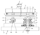
- Figure 3 is a longitudinal sectional view showing the structure of the blanking unit and the core laminator of the adhesive laminated core manufacturing apparatus shown in Figs.
- FIG. 4 is a cross-sectional view schematically showing the core laminator shown in FIG.
- FIG. 5 is a cross-sectional view schematically illustrating a process of manufacturing laminated cores in an inside (laminate hole) of the core laminator shown in FIG. 4;
- FIG. 5 is a cross-sectional view schematically illustrating a process of manufacturing laminated cores in an inside (laminate hole) of the core laminator shown in FIG. 4;
- FIG. 6 is a perspective view showing an example of an adhesive laminated core manufacturable by the present invention and a lamina member for the same;
- FIG. 7 is a cross-sectional view showing the core laminator shown in FIG. 4 separated into three regions;
- FIG. 8 is a cross-sectional view of the squeeze unit, the heating unit, and the pinch unit of the core laminator shown in FIG. 7 separately;
- FIG. 9 is a cross-sectional view showing the cooling system of the core laminator shown in FIG. 7 separated into three regions;
- FIG. 10 is a perspective view showing a squeeze member of the squeeze unit shown in FIG.
- FIG. 11 is a perspective view and a sectional view of the cylinder of the squeeze unit shown in FIG.
- FIG. 12 is a plan view schematically showing an embodiment of the pinch unit shown in FIG. 4; FIG.
- FIG. 13 schematically shows the rotation mechanism of the core laminator shown in FIG. 3;
- FIG. 14 is a plan view showing a rotation operation of the core laminator shown in FIG.
- FIG. 15 is a view illustrating an embodiment of an interlayer division unit of the apparatus for manufacturing an adhesive laminate core shown in FIGS. 1 and 2;
- FIG. 16 is a view illustrating a process of forming interlayer division protrusions on a material by the interlayer division unit illustrated in FIG. 15;
- FIG. 17 is a view showing a state in which the protrusion forming tool of the protrusion forming unit shown in FIG. 15 is retracted (falled);
- FIG. 18 is a view showing a lamination state of lamina members formed by the adhesive laminate core manufacturing apparatus shown in FIG. 15; FIG.
- FIG. 19 is a view showing a process procedure for manufacturing an example of the laminated core shown in FIG. 9;
- FIG. 20 is a view showing an adhesive laminated core manufacturing apparatus according to another embodiment of the present invention.
- FIG. 21 is a view showing an interlayer division unit of the adhesive laminated core manufacturing apparatus shown in FIG. 20; FIG. And
- FIG. 22 is a view showing a lamination state of lamina members formed by the adhesive laminate core manufacturing apparatus shown in FIG. 20; FIG.
- An embodiment of the present invention is a core laminator (Core Laminator) to form a laminated core by integrating a predetermined number, that is, a predetermined number of lamina members by an interlayer adhesive method, and an adhesive laminated core manufacturing apparatus having the same.
- a lamina member having a predetermined shape is formed by blanking a strip-shaped material that is continuously transferred, for example, by a distance of a predetermined pitch.
- B is a core manufacturing apparatus for manufacturing cores such as motors and generators by integrating members in an interlayer adhesive manner.
- the core laminator according to the present embodiment is a laminating apparatus for forming an adhesive laminate core by integrating lamina members having a predetermined shape formed by blanking by interlayer bonding, and an adhesive laminate core manufacturing apparatus according to the present embodiment.
- a core manufacturing apparatus including a blanking unit for blanking and the core laminator.
- an embodiment of the present invention is a device used to manufacture a laminated structure core, that is, a laminated core in one mass by integrating lamina members with an adhesive between layers, for example, an adhesive layer on a surface. After receiving the coated strip-shaped material (steel sheet for core-coating with adhesive layer), the above-described core or laminated core is produced, or after the strip-shaped material without adhesive is applied, the adhesive is applied to the surface of the material.
- the present invention relates to a core laminator for producing an adhesive laminated core and to a core manufacturing apparatus having the same.
- the laminated core forms at least a portion of the iron core for the stator or rotor.
- Adhesive lamination core manufacturing apparatus while passing through the band-shaped material (S) to form a predetermined number of lamina members (L) in sequence, by laminating the predetermined number of laminates by lamination B is based on a press system capable of sequentially manufacturing laminated cores C comprising members.
- the core laminator 100 forms a laminated core by integrating a lamina member by an interlayer bonding method.
- the adhesive laminated core manufacturing apparatus (hereinafter referred to as a 'core manufacturing apparatus') includes the core laminator 100 and the blanking unit 200.
- the blanking unit 200 is a configuration in which the lamina members L are sequentially formed by blanking a material S continuously transferred, for example, a steel strip for motor core manufacturing, and blanking the material S. Thus, the lamina members L are sequentially introduced into the core laminator 100.
- the core laminator 100 is integrated while passing through the lamina members L sequentially formed by the blanking unit 200. More specifically, the core laminator 100 integrates an adhesive existing between the layers of the lamina members L. By heating, a plurality of lamina members L are integrated into one mass.
- the core laminator 100 includes a heating unit 110, a pinch unit 120, a squeeze unit 130, a guide 140, and a rotation driver 150. It is configured to include).
- the heating unit 110 is a hollow configuration in which a plurality of lamina members (L) are integrated by heating an adhesive existing between the layers of the lamina members to form the laminated core.
- the pinch unit 120 is rotatably provided on the lower side of the heating unit 110, and has a hollow type in which side pressure is applied to the laminated core C to prevent the laminated core C from falling. Configuration. That is, the pinch unit 120 is configured to hold the laminated core C under the heating unit 110.
- the squeeze unit 130 is a hollow configuration, the cylinder 131 rotatably provided on the upper side of the heating unit 110, and the hollow squeeze fixed inside the cylinder 131 It comprises a member 132.
- the squeeze member 132 applies a side pressure to the lamina members L moving to the heating unit 110.
- the squeeze member 132 fastens the outer surface of the lamina members L such that the lamina members L pass through the inside of the squeeze member 132 in a fitted state.
- the lamina members L are pushed down by the blanking unit 200 so as to step one step (thickness of one lamina member) inside the core laminator 100 (laminate hole) 100a. Pass by).
- the squeeze member 132, the guide 140, and the pinch unit 120 form the laminate hole 100a.
- the guide 140 is provided inside the heating unit to guide the movement of the lamina members L in the heating unit 110, and the pinch unit 120 and the squeeze unit 130. It can be rotated by following.
- the rotation driver 150 is connected to the squeeze unit 130 and the pinch unit 120 to rotate the cylinder 131 and the pinch unit 120 selectively at an equal angle.
- a cooling system 160 is provided in the lower mold 20 on which the core laminator 100 is installed, that is, the lower mold 20 supporting the squeeze unit 130, the heating unit 110, and the pinch unit 120.
- the cooling system 160 includes a first cooling unit 160A for cooling the squeeze unit 130 and supporting rotation of the cylinder 131, and a second cooling unit surrounding the heating unit 110 ( 160B) and a third cooling unit 160C surrounding the pinch unit 120 and supporting rotation of the pinch unit 120.
- the squeeze member 132 is fixed to the inner circumferential surface of the cylinder 131 and integrally behaves with the cylinder 131.
- the squeeze member 132 may be formed of a hollow ring-shaped structure (squeeze ring) that is fixed inside the cylinder 131 and penetrates vertically.
- the outer circumferential surface of the squeeze ring is in close contact with the inner circumferential surface of the cylinder 131 in an intimate manner, for example, by a press-fit method, so that the squeeze ring can be fixed inside the cylinder 131 but the squeeze member 132
- the fixing method of is not limited to this.
- An inner space of the core laminator 100 that is, the lamination hole 100a is a space in which the lamina members L are stacked in a vertical direction and continuously move and are integrated.
- the core laminator 100 is integrated. Through is formed in the vertical direction.
- the heating unit 110 is a device for heating the adhesive existing between the layers of the lamina member (L), in the present embodiment by curing the adhesive by high frequency induction heating, that is, the heated object, that is, the multilayer lamina member (L) And a high frequency induction heater to integrate them. Since the high frequency induction heating itself is known, further description thereof is omitted, and the present invention provides a high frequency induction as a method of efficiently curing the adhesive existing between the layers of lamina members and minimizing the thermal effect on the surroundings. Start heating.
- the heating unit 110 is a hollow structure that penetrates in the vertical direction, and a curing hole is formed in the heating unit 110 to pass through the lamina members and to form a curing space of the adhesive.
- a guide 140 for guiding the movement of the lamina members L is provided, and the guide 140 is made of a non-conductive material, more specifically, an engineering ceramic material so as not to be affected by high frequency induction heating. It is desirable to have.
- the guide 140 may be both a block structure of an integral hollow structure such as a ring type or a barrel type, or a divided structure that is spaced apart from each other in the heating unit.
- a gap between the inner circumferential surface of the heating unit 110 and the guide 140 is observed. It is preferable that a gap is formed.
- the pinch unit 120 the product discharged downward from the heating unit 110, that is, the laminated core (C) formed by the integration of the lamina member (L) is the heating unit 110 Prevents it from falling momentarily while passing.
- the pinch unit 120 is provided on the lower side of the heating unit 110, by applying a side pressure to the laminated core (C) to prevent the collapse of the laminated core (C).
- the squeeze unit 130 in particular the squeeze member 132 is a pressure (side pressure) to the side of the lamina member (L) to move down toward the heating unit 110 from the upper side of the heating unit 110 It is added to tighten the lamina member (L), to induce the lamination of the lamina member (L).
- the squeeze member 132, the lamina members (L) formed sequentially by the blanking of the material (S) is the inlet portion of the laminate hole (100a), that is, the upper side of the heating unit
- the lamina member (L) is configured to apply a lateral pressure to the lamina member (L) so as to be stacked in the aligned state, the squeeze member (132) while sequentially entering the interior of the squeeze member (132) It is laminated in the state of being fitted inside.
- the squeeze member 132 clamps the outer edges of the lamina members L and linearly aligns the lamina members introduced into the laminate hole 100a coaxially in the inlet region of the laminate hole.
- the squeeze member 132 aligns the lamina members (L) in a straight line on the upper side of the heating unit (110).
- the lamina members (L) are stacked in an aligned state by the squeeze member 132, and enter the high frequency induction heater, that is, the heating unit 110, through the squeeze member 132.
- the squeeze member 132 may be made of a special steel, for example, SKD-11.
- the blanking unit 200 blanks the material to form the lamina members L in sequence, and the lamina members L inside the core laminator 100, in particular the The squeeze member 132 is sequentially supplied and laminated.
- the blanking unit 200 includes a blanking punch 210 provided in the upper mold 10 and a blanking die 220 provided in the lower mold 20.
- the blanking unit 200 forms a lamina member L having a predetermined shape by blanking the material S that continuously passes between the blanking punch 210 and the blanking die 220 by one pitch. .
- the lamina member (L) refers to a single layer of thin sheet produced by blanking the material (S).
- the laminated core C is configured to form at least a part of a stator or a rotor in a device such as a motor or a generator.
- the blanking punch 210 is provided in the upper mold 10, which can rise and fall facing the lower mold 20, more specifically, in the upper frame 11 of the upper mold.
- the blanking die 220 has a blanking hole 221 facing the blanking punch 210.
- the blanking die 200 is provided in the die frame 22 more specifically than the lower die 20, and is stacked on the core laminator 100. It is apparent that the shape of the lamina member L is determined by the shape of the blanking die 220, more specifically, the shape of the blanking hole 221.
- the blanking punch 210 is lifted once by the upper die 10 whenever the material S moves by a predetermined pitch.
- the material S passes one pitch between the upper mold 10 and the lower mold 20 by one stroke of the press, that is, every stroke of the blanking punch 210, and before the blanking process.
- Projection molding is performed at predetermined timings.
- the squeeze member 132 is stacked below the blanking die 220 so as to be coaxial with the blanking die 220, and the heating unit 110 is installed below the squeeze member 132. do.
- the lamina member (L) is represented smaller than the blanking die 220 and the squeeze member 132, it is apparent in the art that both sizes are substantially the same. And a lamina member having the same shape and size as the blanking hole of the blanking die 220 is formed, and the lamina members L have a circumference around the inner circumference of the laminate hole 100a, in particular the squeeze member 132. Close to) and pass downward.
- the dotted line is a portion where interlayer adhesion is performed
- the solid line is a portion where interlayer division is performed.
- the squeeze member 132 supports side surfaces (eg, edges) of the lamina members L for sequential lamination of the lamina members and prevents misalignment or misalignment of the lamina members L.
- it may be composed of a squeeze ring penetrated in the same shape as the inner hole of the blanking die 220, that is, the blanking hole.
- the squeeze member 132 may be formed in a cylindrical ring structure penetrating in the vertical direction, but is not limited thereto.
- the blanking unit 200 blanks the material
- the core laminator 100 is an apparatus for integrating lamina members L sequentially manufactured by blanking, and the blanking die 220.
- the laminated hole 100a is coaxially provided with a lamination hole that is integrated while passing through the lamina members L sequentially stacked by the blanking unit 200.
- the pinch unit 120 applies a side pressure to the product (lamination core) passing through the inside of the pinch unit to help the alignment of the product (C) moving downward from the heating unit 110 and the product, that is, the laminated core Prevent sudden drop of (C).
- the pinch unit 120 includes a pinch block 121 and an elastic member that supports elastically the pinch block 121, that is, a pinch spring 122, and the laminated core C coming out of the heating unit 110. By holding the side (border) of the laminated core (C) after passing through the heating unit 110 to prevent it from falling quickly to the bottom of the laminate hole (100a).
- the pinch blocks 121 are spaced apart from each other along the circumference of the laminated core C in the laminate hole 100a, for example, the laminate hole 100a. Plural pieces are installed at predetermined angle units in the.
- the pinch block 121 may be both a moving type and a fixed type fixed in place, but a moving type is preferable in consideration of thermal expansion. 12, when the pinch spring 122 is omitted and the pinch block 121 is fixed in place so that the pinch block 121 does not move, it becomes a fixed type pinch block.
- the pinch block 121 is disposed to be spaced apart at a plurality of positions along the circumference of the laminated core C, and is elastically supported by the pinch spring 122, that is, elastically supported by the elastic member. Lateral pressure can be applied.
- the blank die 220, the squeeze member 132, the guide 140, and the pinch unit 120 are disposed in the laminator installation hole of the lower mold 10 in the vertical direction to form the above-described laminate hole 100a.
- a take-off support 300 supporting the bottom of the product (laminated core C) discharged through the lamination and curing process is provided to be elevated.
- the ejection support 300 descends while supporting the bottom surface of the laminated core C, which is present at the bottom of the laminate hole 100a, and when the ejection support 300 reaches the bottom of the laminate hole, an ejection cylinder (not shown). (Not shown) to push the laminated core (C) sideways toward the product take-out passage to help take out the product. Thereafter, the take-out base 300 is raised again to repeat the process of supporting the subsequent laminated core.
- a cooling system 160 is applied to the lower mold 20 for the core laminator 100. As shown in FIG. 9, the cooling system 160 cools the squeeze unit 130 and surrounds the heating unit 110 and the first cooling unit 160A supporting the rotation of the cylinder. And a second cooling unit 160B and a third cooling unit 160C surrounding the pinch unit.
- the squeeze member 132 is fixed inside the rotatable cylinder 131 so as to be integral with the cylinder 131. In other words, the cylinder 131 and the squeeze member 132 rotate integrally.
- the outer circumferential surface of the squeeze member 132 that is, the outer circumferential surface of the squeeze ring (hereinafter, the same reference numeral as the 'squeeze member') is in close contact with the inner circumferential surface of the cylinder 131, and the cylinder 131
- a cooling passage 133 for cooling the squeeze unit 130 is formed at the contact interface of the squeeze ring 132.
- the cooling passage 133 of the squeeze unit guides the helical flow of the cooling fluid (hereinafter referred to as 'first cooling fluid') at the contact interface between the cylinder 131 and the squeeze ring 132.
- the cooling passage 133 is connected to the cooling system 160 to guide the flow of the first cooling fluid.
- an inlet 133a and an outlet 133b of the cooling passage are formed at a predetermined distance from each other, and the first cooling fluid is disposed at the contact interface.
- the squeeze member 132 and the cooling of the cylinder 131 is realized while flowing spirally.
- the cooling passage 133 is formed on the inner circumferential surface of the cylinder 131 and / or the outer circumferential surface of the squeeze member 132 to connect the inlet portion 133a and the discharge portion 133b of the cooling passage. It may be configured to include a groove 133c.
- the spiral cooling groove 133c is formed on the outer circumferential surface of the squeeze ring 132, and connects the inlet portion 133a and the discharge portion 133b of the cooling passage and the surface of the squeeze ring 132
- the spiral flow of the cooling fluid is formed, but is not limited thereto, and may be formed on the inner circumferential surface of the cylinder 131 as described above.
- the inlet portion 133a and the outlet portion 133b of the cooling passage are closed loop shapes, that is, a circular shape, and are formed along the circumference of the outer circumferential surface of the squeeze ring 132, respectively. More specifically, a groove (groove) of the circulation type is formed in the upper outer surface and the lower outer peripheral surface of the squeeze ring 132, respectively.
- the inlet 133a is formed in an annular shape at the lower end of the squeeze ring 132
- the discharge part 133b is formed in an annular shape at the top of the squeeze ring 132, but the reverse arrangement It is also possible to have a structure that the discharge portion is formed on the upper outer peripheral surface of the squeeze ring and the inlet is formed on the lower outer peripheral surface.
- air is applied as the cooling fluid, but is not limited thereto.
- the squeeze unit 130, the guide 140, and the pinch unit 120 of the core laminator 100 are rotatably provided on the lower mold 20 for uniform thickness of the laminated core.
- the squeeze unit 130, the guide 140, and the pinch unit 120 simultaneously rotate integrally by a predetermined angle unit, for example, 120 ° at a predetermined timing, thereby reducing the thickness variation of each part of the laminated core C. To improve the squareness and flatness.
- the squeeze member 132 is fixed to the inside of the cylinder 131
- the cylinder 131 is the first cooling unit 160A is fixed to the lower die 20, more specifically, the upper fixed
- the block 161 is rotatably installed.
- the upper fixing block 161 is fixedly installed in the lower mold 20, the cylinder 131 is provided rotatably inside the upper fixing block 161.
- the squeeze member 132 rotates together with the cylinder 131, and upper bearings B1 and B2 are provided inside the upper fixing block 161 to rotatably support the cylinder 131.
- the upper fixing block 161 in this embodiment is a structure in which a plurality of bodies are stacked / assembled, but is not limited thereto.
- the cylinder 131 is a hollow cylinder, the upper end of the cylinder 131 is formed with an upper flange 131f protruding out of the cylinder 131, the lower end of the cylinder 131 is the cylinder ( 131 protrudes inward.
- the upper flange 131f is in surface contact with the bottom surface of the blanking die 220, and the lower end of the cylinder 131 surrounds the lower end of the squeeze member 132.
- the squeeze member 132 is press-fitted into the cylinder 131, and the blanking die 220 is fixed coaxially to the upper end of the cylinder 131. Accordingly, the blanking die 220 rotates integrally with the squeeze unit 130 and may be fixed to the cylinder 131 by a fastening member such as a bolt (not shown).
- the upper fixing block 161 may include an upper support 161 a rotatably supporting an upper portion of the cylinder 131, a lower support 161 b rotatably supporting a lower portion of the cylinder 131.
- the intermediate support 161c is provided between the upper support 161a and the lower support 161b to support the load of the upper support 161a.
- the upper fixing block 161 is provided in the die holder 23, the first upper bearing (B1) between the inner surface of the upper support 610 and the upper outer surface of the cylinder 131. ) Is provided, and a second upper bearing B2 is provided between the inner surface of the lower support 161b and the lower outer surface of the cylinder 131.
- the gap between the upper flange 131f and the upper support 610 is sealed to prevent leakage of the cooling fluid (air in this embodiment) of the squeeze member 132.
- the cooling system 160 is provided with a cooling path through which a cooling fluid (hereinafter referred to as 'second cooling fluid') flows.
- a cooling fluid hereinafter referred to as 'second cooling fluid'
- the first cooling fluid and the second cooling fluid may be the same or different.
- a cooling path 161d through which the second cooling fluid flows is formed in the first cooling unit 160A.
- the cooling path 161d is provided in the upper fixed block 161 of the first cooling unit.
- the cooling path 161d is formed in the lower support 161b, and is water-cooled to cool the upper fixing block 161 by circulation of water, or other such as oil or air. Cooling fluid may also be used, and a cooling furnace may also be applied to the upper support 610 and the intermediate support 630.
- the upper fixing block 161 may include a fluid supply part 161e for supplying the first cooling fluid to the spiral cooling groove 133c of the squeeze member, and the spiral cooling groove 133c of the squeeze member.
- a fluid discharge part 161f for discharging the first cooling fluid is provided.
- the first cooling fluid is air
- the fluid supply part 161e is an air supply part for supplying cooling air
- the fluid discharge part 161f is an air discharge part for discharging air.
- the air supply part 161e is provided at the lower supporter 161b to introduce air into the inlet part 133a of the cooling flow path formed on the outer circumferential surface of the squeeze member 132.
- the air discharge part 161f is provided in the upper support 161a, and implements the exhaust in the upper portion of the squeeze member 132.
- the lower groove of the squeeze member 132 that is, the cooling air supplied to the inlet 133a, spirally flows along the spiral cooling groove 133c, so that the upper groove of the squeeze member ie Heat is exchanged with the squeeze member 132 while flowing to the discharge portion 133b of the cooling passage.
- the cylinder 131 includes a fluid introduction groove 131a, a fluid discharge groove 131b, a fluid supply hole 131c, and a fluid discharge hole 131d.
- One of the fluid supply hole 131c and the fluid discharge hole 131d may be configured such that the first cooling fluid, more specifically, the cooling air, directly contacts the bottom surface of the blanking die 220 during flow. It is connected to an exposure flow path 131e formed at an upper end of the cylinder 131, and the exposure flow path 131e is covered by the blanking die 220.
- the fluid introduction groove 131a is formed in a circular shape on an outer circumferential surface of the cylinder 131 in order to receive the cooling fluid into the cylinder 131.
- the fluid discharge groove 131b is formed in a circular shape on the outer circumferential surface of the cylinder 131 together with the fluid introduction groove 131a.
- the fluid discharge groove 131b is formed at a position spaced apart from the fluid introduction groove 131a by a predetermined distance.
- the fluid supply hole 131c is formed in the fluid introduction groove 131a and is connected to the inlet 133a of the cooling passage through the cylinder 131.
- the fluid discharge hole 131d is formed in the fluid discharge groove 131b and is connected to the discharge part 133b of the cooling passage through the cylinder 131.
- the fluid introduction groove 131a constituting the closed loop on the lower outer circumferential surface of the cylinder 131 is formed in a circular shape along the circumference of the cylinder 131.
- a fluid supply hole 131c penetrating the cylinder 131 is formed in the fluid introduction groove 131a to introduce air into the cylinder 131.
- the fluid supply hole 131c communicates with a lower end of the spiral cooling groove 133c, more specifically, an inlet 133a of the cooling flow path.
- a fluid discharge groove 131b constituting a closed loop is circulated along the circumference of the cylinder 131 on an upper outer circumferential surface of the cylinder 131, for example, an outer circumferential surface of the upper flange 131f.
- the fluid discharge hole 131d penetrating the cylinder 131 is formed in the discharge groove 131b.
- the fluid discharge hole 355 communicates with an upper end portion of the spiral cooling groove 341, more specifically, the discharge portion 133b of the cooling passage.
- the fluid supply hole 131c is connected to a lower groove formed in the squeeze member, that is, the inlet part 133a, and the fluid discharge hole 131d is formed in an upper groove formed in the squeeze member, that is, the discharge part ( 131b). Therefore, in the present exemplary embodiment, the first cooling fluid is supplied to the lower portion of the cylinder 131 and then discharged from the upper portion of the cylinder 131. However, the flow of the cooling fluid may be reversed so that the first cooling fluid is supplied to the upper portion of the cylinder 131 and then discharged from the upper portion of the cylinder 131.
- the fluid introduction groove 131a is formed horizontally at the same height as the inlet portion 133a of the cooling passage, and the fluid discharge groove 131b is the same height as the outlet portion 133b of the cooling passage. It is formed in the horizontal to the fluid supply hole 131c and the fluid discharge hole (131d) penetrates the cylinder 131 horizontally horizontally. A plurality of fluid supply holes 131c and fluid discharge holes 131d may be formed in the cylinder 131, respectively.
- annular fluid introduction grooves 131a and the fluid discharge grooves 131b that form a closed loop are formed on the lower outer and upper outer surfaces of the cylinder 131, even if the cylinder 131 rotates. Since the air supply unit 161e and the air discharge unit 161f may be constantly connected to the fluid introduction groove 131a and the fluid discharge groove 131b, the introduction and discharge of the first cooling fluid, ie, air, may be stable. .
- an air supply hole for guiding air from the air supply unit 161e to the fluid introduction groove 131a is formed in the lower support 161c, and the fluid discharge groove 131b is formed in the upper support 161a. Exhaust holes for air discharge from the outside to the outside are formed.
- the cooling air When cooling air is discharged to the outside of the cylinder 131 through the fluid discharge hole 131d at the outer circumferential surface of the squeeze member 132, the cooling air is directly exchanged with the blanking die 220.
- the exposure path 131e described above is formed at an upper end of the cylinder 131. That is, in the present embodiment, the cooling air is discharged from the inside of the cylinder 131 to the outside to be in contact with the blanking die 220 to perform heat exchange.
- the exposed flow path 131e has an open top structure, and is circulated along the circumferential direction at the upper end of the cylinder 131, more specifically, at the upper end of the inner circumferential surface of the cylinder 131 (see FIG. 11A). It may be formed, or may be divided into a plurality of upper ends of the inner circumferential surface of the cylinder (131) (see Fig. 11 (b)).
- the upper fixing block 161 includes an oil supply unit 161g for introducing oil for lubrication and / or cooling of the upper bearings B1 and B2 into the upper bearings B1 and B2, and the upper bearing ( An oil discharge part 161h for discharging oil from B1 and B2 is provided, thereby preventing damage to the upper bearings B1 and B2 for rotationally supporting the cylinder 131 and preventing the upper bearings B1 and B2.
- the long life of the can be long, and further may perform the cooling function of the upper fixing block (161).
- the third cooling unit 160C rotatably supports the pinch unit 120 and surrounds the pinch unit 120.
- a cooling path 163a is formed in the third cooling unit 160C to guide the flow of the cooling fluid.
- the pinch block 122 is provided in the rotatable pinch housing 123 to rotate together with the pinch housing 123, and the pinch housing 123 is fixed to the lower mold 20. It is rotatably supported by the fixing block of the three cooling parts 160C, that is, the lower fixing block 163.
- the lower fixing block 163 is fixedly installed in the lower mold 20, and the pinch housing 123 is rotatably provided in the lower fixing block 163.
- a lower bearing B3 is rotatably supported inside the lower fixing block 163 to rotatably support the pinch housing 123.
- the lower fixing block 163 is a single body having an annular hollow shape and a circumferential wall having a 'b' cross section, but is not limited thereto.
- the lower fixing block 163 is provided with an oil supply unit / discharge unit for supplying (163b) / discharging (163c) the lubricating and / or cooling oil to the lower bearing B3 of the lower fixing block.
- the oil supply / discharge unit of the lower fixing block 163 may also perform a cooling function of the lower fixing block 163.
- a cooling technique of water-cooling or air-cooling may be applied to the lower fixing block 163, and the cooling path 163a of the third cooling unit is formed in the lower fixing block 163.
- a second cooling unit 160B is provided between the upper fixing block 161 and the lower fixing block 163 to accommodate the heating unit 110, and the second cooling unit 160B is heated.
- the cooling path 162a surrounding the unit 110 and in which the cooling fluid flows is also provided in the second cooling unit 160B.
- the heating unit 110 is provided with a fixing block, that is, the middle fixing block 162 of the second cooling unit 160B.
- the intermediate fixing block 162 covers the upper side and the circumference (outer circumferential surface) of the heating unit 110, and the intermediate fixing block 162 has a cooling path of the receiving groove and the second cooling unit of the heating unit 110. 162a is formed.
- the cooling passage 162a of the intermediate fixed block may be water-cooled to cool the intermediate fixed block 162 by water circulation, or other cooling fluid such as oil or air may be used.
- the inside of the intermediate fixing block 162 is provided with the above-described guide 140, the guide 140 is driven by the rotation of the cylinder 131 and the pinch housing 123 and the cylinder 131 and It rotates together with the pinch housing 123.
- a lower end of the cylinder 131 is in contact with an upper end of the guide 140, and the pinch housing 123 is in contact with a lower end of the guide 140 more than the pinch unit.
- the lower end of the cylinder 131 is mounted on the upper end of the guide 140, and the lower end of the guide 140 is mounted on the pinch unit 120, in particular the pinch housing 123.
- the guide 140 may be driven by the cylinder 131 and / or the pinch housing 123 to rotate at the same angular speed.
- the cylinder 131 and the pinch unit 120 rotates at the same angle at the same time.
- the cylinder 131 and the pinch unit 120 are provided with pulleys of the rotary driver 150, respectively.
- a pulley 151 fixed to the cylinder 131 is referred to as a first pulley
- a pulley 152 fixed to the pinch unit, in particular the pinch housing 123 is referred to as a second pulley.
- the first pulley 151 and the second pulley 152 is connected to the driving pulley 153 as a driven pulley receives a driving force.
- first pulley 151 and the second pulley 152 in the present embodiment has the same outer diameter so that the cylinder 131 and the pinch housing 123 rotates at the same angular speed, one
- the drive pulley 153 is connected by belts 154a and 154b, respectively.
- the drive pulley 153 is rotated by a motor (M), the motor (M) and the drive pulley 153 is connected by a belt-pulley power transmission mechanism by a drive belt 154c, but the power transmission method Of course, this is not limited.
- the driving pulley 153 When the driving pulley 153 is rotated by the power of the motor M, the cylinder 131 and the squeeze member 132 rotate by a predetermined angle, for example, by 120 degrees as shown in FIG. 14. can do.
- a core manufacturing apparatus is an apparatus capable of manufacturing a laminated core using a strip-shaped material having an adhesive coated on its surface.
- the core manufacturing apparatus an apparatus capable of manufacturing a laminated core using a steel sheet strip (self-bonding steel sheet; SB steel sheet) formed with a semi-hardened adhesive layer at a predetermined temperature or less
- SB steel sheet self-bonding steel sheet
- the lamina members are sequentially formed by blanking the material, and interlayer division protrusions are formed on the surface of the material at a predetermined interval in conjunction with the blanking, and an adhesive layer existing between the layers of the laminated lamina members is provided.
- the laminated core can be manufactured by heating and melting, and hardening at high temperature.
- the core manufacturing apparatus of one embodiment of the present invention further includes an interlayer division unit 400 for dividing the laminated cores C.
- the interlayer division unit 400 in the present embodiment is a projection forming unit (hereinafter, the same reference numerals as the interlayer division unit is used) for forming the interlayer division projections at predetermined timings in the material.
- the protrusion forming unit 400 when manufacturing the above-described laminated core (C) by using the band-shaped material (S) coated with an adhesive layer (1) on the surface, the division between the laminated core (C) In order to be able to do this, the raw material is pressurized to form a projection P, that is, an interlayer division projection, on the raw material S.
- the protrusion P forms a gap between two lamina members stacked adjacent to each other to reduce the contact area between the lamina members.
- the upper mold 10 is provided to be elevated on the upper side of the lower mold 20 for pressing and blanking the material (S).
- the blanking punch 210 is mounted to the upper die 10 and disposed downstream of the protrusion forming unit 400 on the basis of the conveying direction of the raw material S. Therefore, as described above, the blanking punch 210 blanks the material S while raising and lowering together with the upper die 10.
- the protrusion forming unit 400 forms the above-mentioned protrusion P on the surface of the material S at predetermined cycles.
- the projection forming unit 400 forms the above-described projection P on one side or the other side of the material S each time the blanking progresses a predetermined number of times. 200) can optionally be synchronized (synchronization) configuration.
- the protrusion forming unit 400 forms a protrusion P on the material S in synchronization with the blanking unit 200 whenever it is transferred by a predetermined plurality of pitches of the material S.
- the laminated core C is a laminate composed of ten lamina members, that is, a laminate of ten layers
- the projections P are the same on the surface of the workpiece S every 10 pitches of the workpiece. It is formed in a pattern.
- the protrusion forming unit 400 includes a protrusion forming tool 410 for pressing the one side surface of the material and protruding the interlayer division protrusion to the opposite side, and a forming die 420 facing the protrusion forming tool 410. It is configured to include).
- the projection forming tool 410 presses the material at regular intervals in synchronization with the blanking unit 200 in order to form the interlayer partitioning projection P in the material S.
- the protrusion forming tool 410 is provided on any one of the upper support (10a) and the lower support (20a) disposed opposite to each other, the other is provided with the forming die 420, The material S passes by one pitch between the upper support 10a and the lower support 20a.
- the protrusion forming tool 410 is provided on the lower support 20a, and the forming die 420 is provided on the upper support 10a, but the reverse structure as in the embodiment described below Of course it is also possible.
- the protrusion forming tool 410 is provided on the lower support 20a to press up one side, that is, the bottom surface of the material S, and the forming die 420 is the upper support 10a. It is provided in to support the other side, that is, the upper side of the material (S).
- the protrusion forming tool 410 presses one side (bottom) of the material upwards at regular intervals in synchronization with the blanking unit 200.
- the interlayer division protrusion P is protruded upward from the upper surface of the material S, and the protrusion forming unit 400 of the present embodiment locally pressurizes one side of the material. It can also be called an embossing device (Embossing Apparatus) to protrude to the opposite side.
- embossing Apparatus Embossing Apparatus
- the upper support 10a may be a structure separated from the upper mold 10, or may be integrated with the upper mold 10 described above, as shown in FIG. 2.
- the upper support 10a may be integrated with the upper die 10 as a part of the upper die 10.
- the lower support 20a may also be a structure separated from the lower mold 20 at intervals from the lower mold 20, or may be integrated with the lower mold 20 described above as shown in FIG. 2.
- both sides both sides (upper side and lower side) may be used both sides of the coating material coated with the adhesive layer (1), the adhesive layer is coated only on one side of the upper side and the lower side.
- One side coating material may be used.
- the laminated core is manufactured using the material S having the adhesive layer 1 formed on both sides thereof.
- the lamina member is in contact with the interlayer dividing protrusion (for example, point contact).
- the contact area is localized between the lamina member on which the interlayer division projections are formed, and the interlayer division may be performed based on a predetermined number of sheets.
- the forming die 420 is provided in the upper support 10a, and the upper support 10a is integral with the upper die 10, that is, the upper support 10a as shown in FIG. Is a part of the upper die 10, the forming die 420 is provided in the upper die 10 together with the blanking punch 210.
- the protrusion forming tool 410 is provided on the lower support (20a) to press the lower side (bottom surface) of the material (S), the lower support (20a) is integral with the lower mold 20 In other words, when the lower support 20a is a part of the lower mold 20 as shown in the example shown in FIG. 2, the protrusion forming tool 410 may be connected to the lower mold 20 together with the blanking die 220. ) Is provided.
- the protrusion forming tool 410 is provided directly below the forming die 420 so as to face the forming die 420, and the forming die 420 moves up and down together with the upper die 10.
- the forming die 420 has a protrusion forming groove 421 upwardly recessed from a bottom of the forming die 420, and in the present embodiment, the forming die 420.
- a plurality of protrusion forming grooves 421 are formed at a bottom of the protrusion forming tool 410, and the protrusion forming tool 410 has a plurality of pressing protrusions facing the protrusion forming grooves 421.
- the protruding forming tool 410 is provided to be elevated on the lower support (20a), as described above when the lower support (20a) is integral with the lower die 20, the elevating to the lower die 20 It is possible.
- the lower die 20 is formed with a tool receiving portion 20b, the projection forming tool 410 is provided to be elevated in the tool receiving portion (20b).
- the protrusion forming tool 410 is configured to include a lifting tool base 411, and the material pressing portion 412, that is, the pressing protrusion provided in the tool base 411. Accordingly, the tool base 411 is installed to be elevated in the tool receiving portion 20b, and the tip (upper end) of the material pressing portion 412 has a shape corresponding to the protrusion forming groove 421.
- the protrusion forming groove 421 is not limited to the shape of the triangular groove or the protrusion forming groove 421.
- the protrusion forming groove 421 may be changed into various shapes such as hemispherical or semi-elliptic. However, a shape that is minimized at an interface where interlayer division is made is more preferable.
- the upper mold 10 may be divided into a plurality of bodies along the conveying direction of the material (S), or may be formed of one integrated body.
- the lower mold 20 may also be divided into a plurality of bodies along the conveying direction of the material S, or may form one integrated body.
- the core manufacturing apparatus shown in FIG. 2 is a press structure including an integrated upper mold and an integrated lower mold.
- the upper mold 10 is provided with a pusher, that is, a pressing member for pressing the material S toward the lower mold 20. Therefore, when the upper mold 10 is lowered, the upper side of the material S is pushed downward by the pusher 12, so that the material S is pressed toward the lower mold 20 side.
- a pusher that is, a pressing member for pressing the material S toward the lower mold 20. Therefore, when the upper mold 10 is lowered, the upper side of the material S is pushed downward by the pusher 12, so that the material S is pressed toward the lower mold 20 side.
- the upper mold 10 is configured to include an upper frame 11 provided on the upper side of the lower mold 20 so as to be elevated, and the pusher 12 provided on the lower side of the upper frame 11.
- the blanking punch 210 is provided in the upper frame 11 more specifically than the upper mold 10 together with the pusher 12.
- the pusher 12 functions as a stripper in the blanking process and the piercing process, and simultaneously presses the material S toward the lower mold 20 for the protrusion forming process and the blanking process.
- a compression plate or a pressure plate in this embodiment, it is a plate-shaped pushing plate.
- the elevating member for example, a coil spring; 12a
- the elevating member for example, a coil spring; 12a
- the lower mold 20 is configured to include a base frame 21 (Bolster) forming a base of the lower mold 20 and lower dies 22 and 23 provided above the base frame.
- a base frame 21 Bolster
- the protrusion forming tool 410 is installed on the lower dies 22 and 23.
- the lower dies 22 and 23 may be divided into a die frame 22 forming an upper side of the lower die and a die holder 23 provided below the die frame 22.
- the die holder 23 supports the die frame 22 and is stacked on the base frame 21 to be supported by the base frame 21, but the structure of the lower mold 20 is limited thereto.
- the die holder 23 may also be divided into a plurality of parts.
- the blanking die 220 and the projection forming tool 410 are installed on the lower dies 22 and 23.
- the molding die 420 is supported by the upper frame 11 so as to pass through the pusher 12 to support the upper surface of the material S.
- the pusher 12 is formed with a die hole 12d through which the forming die 420 passes.
- the protrusion forming tool 410 is lifted by the elevator 500, for example, a lift mechanism such as a cam mechanism or a hydraulic / pneumatic cylinder, thereby adjusting the vertical position of the protrusion forming tool 410. That is, when the projection molding is required, the projection forming tool 410 is raised by the elevator 500, so that the tip (top) of the projection forming tool 410 is higher than the upper surface of the lower mold 20. We move upward.
- a lift mechanism such as a cam mechanism or a hydraulic / pneumatic cylinder
- the elevator 500 moves (enters) the protrusion forming tool 410 toward the material S at predetermined intervals, the material S is lowered when the upper die 10 is lowered.
- the lower surface of the material S may be lowered by the pusher and may be pressed upward by the protrusion forming tool 410.
- the elevator 500 is provided in the tool receiving portion 20b of the lower mold, respectively, and is coupled to the protrusion forming tool 410.
- the protrusion forming tool 410 is raised by the elevator 500 to a top dead center at predetermined intervals. After the protrusion forming process is performed, the protrusion forming tool 410 is retracted (falled) by the elevator 500 to prevent contact with the material S until the next cycle.
- the protrusion forming process is performed once every time the material S moves by 10 pitches. Interlayer division between the stacked cores C may be implemented. To this end, the elevator 500 raises the protrusion forming tool 410 once each time the material S moves by 10 pitches.
- the dotted line is a portion where the interlayer adhesion is performed
- the solid line is a portion where the interlayer division is performed by the protrusion P
- the adjacent line is adjacent to the solid line portion (the boundary at which the layer is divided).
- the elevator 500 supports the protrusion forming tool 410 and is provided with a lifting body 510 which is provided to be liftable on the lower tool receiving portion 20b. It is configured to include a lifter 520 for elevating the elevating body (510).
- the lifting body 510 is fixed to the protrusion forming tool 410, and the protrusion forming tool 410 operates integrally with the lifting body 510.
- the lifting rod 530 is coupled to the lifting body 510 by penetrating the lifter 520 in the vertical direction.
- the elevator 500 has a cam structure, and the lifting / lowering of the lifting body 510 is realized by the left and right slides of the lifter 520.
- the elevating body 510 and the elevating rod 530 are raised and lowered in place, and the vertical movement of the elevating body 510 is realized by the horizontal movement of the lifter 520.
- the structure and operation of the elevator is not limited to the above-described example.
- the material S moves through the pusher 12 and the die frame 22 by a certain distance (one pitch) every one cycle of the upper die 10, that is, one stroke of a press. As shown in (a), when a predetermined portion of the material S reaches the projection forming position, the projection forming tool 410 is raised to the top dead center by the elevator 500 at the same time or immediately before. .
- the protrusion forming tool 410 presses the bottom surface of the material (S) upward, thereby forming the above-described protrusion (P) by interaction with the forming die 420.
- a blanking process is performed in the blanking unit 200 simultaneously with the protrusion forming process.
- FIG. 16C illustrates a state in which the upper mold 10 is raised after the protrusion P is formed on the upper surface of the material S. At the same time as or immediately after the upper mold 10 is raised.
- the protrusion forming tool 410 is lowered to the bottom dead center by the elevator 500.
- FIG. 17A illustrates that the protrusion forming tool 410 is lowered so that the protrusion forming tool 410 does not come into contact with the material even when the upper die 10 is lowered and the material S is pressed downward.
- the protrusion forming process does not proceed for a predetermined period.
- FIG. 18 is a view illustrating a lamination state of lamina members formed by an adhesive lamination core manufacturing apparatus according to an exemplary embodiment of the present disclosure, and a lamina member having an upwardly protruding interlayer division protrusion and a lamina laminated thereon. Interlayer division may be made at the boundary between the members.
- the protrusion height of the protrusion P is sufficient to implement the interlayer division.
- the protrusion may be removed by pressing the laminated core C with a separate press after being discharged from the core manufacturing apparatus according to the present embodiment.
- the pressing preventing escape groove 211 of the protrusion P is formed on the surface (bottom surface) of the blanking punch 210.
- FIG. 19 is an example of a process flowchart illustrating a process of molding a lamina member in FIG. 6.
- the material S is transferred while sequentially passing through the piercing processes S1 and S2, the protrusion forming process S3, and the blanking process S4.
- the molding process is performed periodically every time the material S is transferred to a predetermined plurality of pitches, thereby forming interlayer division protrusions (upper protrusions) on the material.
- the order of forming the lamina member L is not limited to the above-described example.
- the protrusion forming unit 400 includes a protrusion forming tool 410 provided in the upper mold 10 and a forming die 420 provided in the lower mold 20. It may be configured.
- the projection forming tool 410 is provided on the upper support (10a of Figure 1) separated from the upper mold 10 at intervals
- Molding die 420 may be provided on the lower support (20a in FIG. 1) separated from the lower die 20 at intervals. That is, the protrusion forming tool 410 and the blanking punch 210 may be installed in different structures, and the forming die 420 and the blanking die 220 may also be installed in different structures. .
- the present embodiment has a structure in which a part (upper support) for supporting the protruding forming tool 410 is a part of the upper mold, and a part (lower support) for supporting the molding die 420 is a part of the lower mold.
- 410 is provided on the upper die 10 together with a blanking punch 210
- the forming die 420 is provided on the lower die 20 together with the blanking die 220.
- the protrusion forming tool 410 in the present embodiment is a structure for pressing down the upper side of the material (S), the projection forming unit 400 is for interlayer division protruding downward from the bottom of the material (S) The protrusion P is formed.
- the protrusion forming tool 410 of the present embodiment is provided directly above the forming die 420 so as to face the forming die 420, and is mounted on the upper mold to form the upper mold 10. We climb together.
- the forming die 420 of the present embodiment has a lower forming groove 421 recessed downward from an upper side of the forming die 420, and a plurality of protrusion forming grooves 421 are formed on the upper side of the forming die 420.
- the upper die 10 is provided with a tool receiving portion 10b for receiving the projection forming tool 410 to be elevated.
- the protrusion forming tool 410 is installed on the upper die 10 to be elevated.
- the upper forming tool 410 is configured to include a lifting tool base 411, the material pressing portion 412 provided in the tool base 411, the material pressing portion 412
- the front end (lower end) of) has a shape corresponding to the protrusion forming groove 421 and has a plurality of pressing protrusions.
- the protrusion forming tool 410 more specifically, the material pressing portion 412, through the pusher 12 to press the upper side of the material (S) down, the above-described implementation It is supported by the upper die 10 described in the example.
- the pusher 12 is formed with a tool hole 12e through which the upper forming tool 410, in particular, the material pressing part 412 penetrates.
- the protrusion forming tool 410 is elevated by an elevator 500, for example, a cam mechanism or an elevator such as a hydraulic / pneumatic cylinder, and the vertical position of the protrusion forming tool 410 is adjusted accordingly. That is, when the projection molding is required, the projection forming tool 410 is lowered by the elevator 500 to advance downward to the bottom dead center.
- an elevator 500 for example, a cam mechanism or an elevator such as a hydraulic / pneumatic cylinder
- the elevator 500 lowers the protrusion forming tool 410 toward the material S at predetermined intervals, the upper surface of the material S is protruded when the upper die 10 is lowered. It may be pressed downward by the forming tool 410.
- the elevator 500 is provided in the tool receiving portion 10b of the upper mold and is coupled to the protrusion forming tool 410.
- the protrusion forming tool 410 is lowered by the elevator 500 to a bottom dead center at predetermined intervals. After the protrusion forming process is performed, the protrusion forming tool 410 is retracted (raised) by the elevator 500 to prevent contact with the material S until the next cycle.
- the elevator 500 supports the protrusion forming tool 410 and is provided with a lifting body 510 which is provided to be liftable in the upper tool receiving portion 10b. It is configured to include a lifter 520 for elevating the elevating body (510).
- the lifting body 510 is fixed to the protrusion forming tool 410, in particular, the tool base 411, and the protrusion forming tool 410 behaves integrally with the lifting body 510.
- the lifting rod 430 is coupled to the lifting body 510 by penetrating the lifter 520 in the vertical direction. Since the operation of the elevator 500 is the same as described in the above-described embodiment, repeated description is omitted.
- FIG. 22 is a view illustrating a lamination state of lamina members formed by the core manufacturing apparatus according to the present embodiment, and a boundary between a lamina member having a downwardly projecting interlayer division protrusion and a lamina member laminated thereon. Interlayer division can be achieved.
- the interlayer division unit for dividing the laminated cores C is not limited to the above-described example.
- the interlayer separation unit may scrape the surface of the material to partially remove the adhesive layer so that the adhesive force is lost, or may locally lose the adhesive strength by locally heating the surface of the material. It may also consist of a device for adding release paper between the lamina members for splitting.
- 1, 2, and 20 illustrate an apparatus for manufacturing a laminated core by receiving a material coated with an adhesive layer on a surface thereof, or a material not coated with an adhesive to apply an adhesive to the material. It is also possible to manufacture the adhesive laminated core by coating, such a core manufacturing apparatus, for example, Japanese Patent No. 5323400, Japanese Patent Laid-Open No. 5-304037, Korean Patent No. 10-1599291 or Patent No. 10-1566492
- the above-described core laminator can also be applied to the core manufacturing apparatus disclosed in the above.
- the present invention relates to the manufacture of cores used as rotors or stators for motors or generators, and is used in the apparatus for manufacturing laminated cores.
- the present invention provides precise lamination of thin sheets formed by blanking, and enables interlayer adhesion between sheets. Can be implemented.
Landscapes
- Engineering & Computer Science (AREA)
- Power Engineering (AREA)
- Manufacturing & Machinery (AREA)
- Manufacture Of Motors, Generators (AREA)
Abstract
Un aspect de la présente invention concerne un dispositif de stratification de noyau d'un appareil de fabrication de noyau stratifié de type adhésif qui forme un noyau stratifié par intégration d'une pluralité d'éléments laminaires passant à l'intérieur de celui-ci. Le stratifié de noyau selon un aspect de la présente invention comprend: une unité de chauffage creuse pour chauffer un adhésif se trouvant entre des couches des éléments de feuille pour intégrer une pluralité des éléments de feuille afin de former le noyau stratifié; une unité de pincement creuse, disposée de façon rotative au-dessous de l'unité de chauffage, pour appliquer une pression latérale au noyau stratifié pour empêcher le noyau stratifié de tomber; une unité de compression creuse qui comprend un cylindre disposé de manière rotative sur le côté supérieur de l'unité de chauffage et un élément de compression, fixé à l'intérieur du cylindre, pour aligner les éléments de feuille dans une ligne sur une ligne coaxiale à partir du côté supérieur de l'unité de chauffage; un guide disposé à l'intérieur de l'unité de chauffage pour guider le mouvement des éléments de feuille dans l'unité de chauffage, le guide étant entraîné en rotation par l'unité de pincement et l'unité de compression; et un dispositif d'entraînement en rotation relié à l'unité de serrage et à l'unité de pincement afin de faire tourner simultanément et sélectivement le cylindre et l'unité de pincement d'une manière équi-angulaire.
Priority Applications (2)
| Application Number | Priority Date | Filing Date | Title |
|---|---|---|---|
| CN201680083758.3A CN108781028B (zh) | 2016-03-18 | 2016-06-16 | 粘合式层叠芯制造装置及其芯层压机 |
| US16/086,310 US10923995B2 (en) | 2016-03-18 | 2016-06-16 | Adhesive laminate core manufacturing apparatus and core laminator therefor |
Applications Claiming Priority (2)
| Application Number | Priority Date | Filing Date | Title |
|---|---|---|---|
| KR10-2016-0032876 | 2016-03-18 | ||
| KR1020160032876A KR101876292B1 (ko) | 2016-03-18 | 2016-03-18 | 접착식 적층코어 제조장치 및 이를 위한 코어 라미네이터 |
Publications (1)
| Publication Number | Publication Date |
|---|---|
| WO2017159926A1 true WO2017159926A1 (fr) | 2017-09-21 |
Family
ID=59850974
Family Applications (1)
| Application Number | Title | Priority Date | Filing Date |
|---|---|---|---|
| PCT/KR2016/006406 Ceased WO2017159926A1 (fr) | 2016-03-18 | 2016-06-16 | Appareil de fabrication de noyau stratifié de type adhésif et dispositif de stratification de noyau associé |
Country Status (4)
| Country | Link |
|---|---|
| US (1) | US10923995B2 (fr) |
| KR (1) | KR101876292B1 (fr) |
| CN (1) | CN108781028B (fr) |
| WO (1) | WO2017159926A1 (fr) |
Cited By (2)
| Publication number | Priority date | Publication date | Assignee | Title |
|---|---|---|---|---|
| EP3514925A1 (fr) | 2018-01-18 | 2019-07-24 | voestalpine Automotive Components Dettingen GmbH & Co. KG | Procédé d'assemblage d'éléments de tôle à des paquets de tôle |
| EP3514926A1 (fr) | 2018-01-18 | 2019-07-24 | voestalpine Automotive Components Dettingen GmbH & Co. KG | Procédé de liaison de parties en tôle à un empilage de tôles |
Families Citing this family (16)
| Publication number | Priority date | Publication date | Assignee | Title |
|---|---|---|---|---|
| JP6543608B2 (ja) * | 2016-12-22 | 2019-07-10 | 株式会社三井ハイテック | 積層鉄心の製造方法及び積層鉄心の製造装置 |
| RS67409B1 (sr) * | 2018-12-17 | 2025-12-31 | Nippon Steel Corp | Lepljivo laminirano jezgro za stator i električni motor |
| CN111266459A (zh) * | 2020-03-03 | 2020-06-12 | 东莞市嘉润耀广实业有限公司 | 一种铁芯模具及内加热方法 |
| KR102238553B1 (ko) * | 2020-05-22 | 2021-04-08 | (주)포스코에스피에스 | 적층코어 제조장치 |
| KR102327978B1 (ko) | 2020-05-22 | 2021-11-17 | (주)포스코에스피에스 | 접착식 적층코어 제조장치 |
| JP7149545B2 (ja) * | 2021-02-24 | 2022-10-07 | 大垣精工株式会社 | 積層鋼板製造装置 |
| CN112802676B (zh) * | 2021-03-31 | 2021-07-27 | 广东昭信智能装备有限公司 | 一种变压器组装线 |
| KR102658452B1 (ko) * | 2021-06-09 | 2024-04-17 | 주식회사 비엠씨 | 가열 접착식 적층 코어 제조 장치 |
| KR102575532B1 (ko) | 2021-10-27 | 2023-09-07 | (주)포스코모빌리티솔루션 | 코어 제조장치 및 제조방법 |
| JP7174191B1 (ja) * | 2022-07-20 | 2022-11-17 | 田中精密工業株式会社 | 積層体払い出し装置及び積層体の払い出し方法 |
| EP4604371A4 (fr) * | 2022-10-13 | 2026-01-14 | Nhk Spring Co Ltd | Dispositif de fabrication de corps empilé et procédé de fabrication de corps empilé |
| CN115632528B (zh) * | 2022-12-21 | 2023-03-28 | 苏州范斯特机械科技有限公司 | 电机层叠铁芯的生产设备及其生产方法 |
| KR20250031839A (ko) | 2023-08-29 | 2025-03-07 | (주)포스코모빌리티솔루션 | 적층코어 제조장치 |
| KR102864323B1 (ko) * | 2023-10-19 | 2025-09-25 | 주식회사 비엠씨 | 가열 접착식 회전 적층 코어 제조 장치 |
| KR102727637B1 (ko) * | 2023-10-27 | 2024-11-07 | 에스제이글로벌 주식회사 | 모터 코어 제조용 고주파 가열장치 |
| KR102711527B1 (ko) | 2023-10-31 | 2024-10-02 | 주식회사 서진캠 | 코어 자동 적층장치 및 이를 이용한 자동 적층 방법 |
Citations (4)
| Publication number | Priority date | Publication date | Assignee | Title |
|---|---|---|---|---|
| JP2009297758A (ja) * | 2008-06-16 | 2009-12-24 | Kuroda Precision Ind Ltd | 積層鉄心の製造装置 |
| JP2010274625A (ja) * | 2009-06-01 | 2010-12-09 | Panasonic Corp | 積層体の製造方法および製造装置 |
| JP2011020132A (ja) * | 2009-07-14 | 2011-02-03 | Pascal Engineering Corp | 積層鉄心製造装置 |
| KR20160028678A (ko) * | 2014-09-04 | 2016-03-14 | 주식회사 포스코티엠씨 | 접착식 적층 코어부재 제조장치 및 온도제어방법 |
Family Cites Families (24)
| Publication number | Priority date | Publication date | Assignee | Title |
|---|---|---|---|---|
| US4464826A (en) * | 1982-07-26 | 1984-08-14 | General Electric Company | Method and apparatus for aligning laminations in a stator core |
| JPH05304037A (ja) | 1992-04-28 | 1993-11-16 | Aida Eng Ltd | 積層コアの製造方法 |
| KR0119014B1 (ko) | 1994-06-09 | 1997-09-30 | 구자홍 | 모터 코어의 적층 접착장치 |
| US5799387A (en) * | 1996-06-05 | 1998-09-01 | L.H. Carbide Corpordation | Lamina stack having a plurality of outer perimeter configurations and an apparatus and method for manufacturing said stack |
| US6163949A (en) * | 1996-06-05 | 2000-12-26 | L.H. Carbide Corporation | Method for manufacturing long, slender lamina stack from nonuniform laminae |
| JP3822020B2 (ja) * | 2000-05-16 | 2006-09-13 | 株式会社コアテック | 積層コアの製造装置 |
| JP2004023829A (ja) * | 2002-06-13 | 2004-01-22 | Matsushita Electric Ind Co Ltd | 積層体の製造方法 |
| JP2006238592A (ja) * | 2005-02-24 | 2006-09-07 | Toyota Motor Corp | スロット紙成形装置 |
| US8127429B2 (en) * | 2006-11-27 | 2012-03-06 | Honda Motor Co., Ltd. | Method for producing ring core |
| KR100856032B1 (ko) | 2007-01-16 | 2008-09-02 | 주식회사 포스코아 | 코아몸체, 코아날개 및 이를 구비한 조립식 적층 코아 |
| KR100849023B1 (ko) | 2007-01-16 | 2008-07-30 | 주식회사 포스코아 | 분할 구조를 가지는 적층 코어 |
| JP4402125B2 (ja) * | 2007-03-14 | 2010-01-20 | 三菱電機株式会社 | 固定子内周真円度修正装置及び固定子内周真円度修正方法 |
| US8276426B2 (en) * | 2007-03-21 | 2012-10-02 | Magnetic Metals Corporation | Laminated magnetic cores |
| JP5375264B2 (ja) * | 2009-03-30 | 2013-12-25 | Jfeスチール株式会社 | 積層コアの製造装置 |
| JP2011066987A (ja) * | 2009-09-16 | 2011-03-31 | Denso Corp | 積層コアの製造方法、積層コア及び回転電機 |
| JP5581903B2 (ja) * | 2010-08-31 | 2014-09-03 | トヨタ紡織株式会社 | 転積装置 |
| KR101599291B1 (ko) | 2014-05-28 | 2016-03-14 | 주식회사 포스코티엠씨 | 접착식 적층 코어부재 제조장치 및 접착제 도포유닛 |
| KR101566492B1 (ko) | 2014-06-25 | 2015-11-06 | 주식회사 포스코티엠씨 | 접착식 적층 코어부재 제조장치 및 접착제 도포유닛 |
| JP5890476B2 (ja) * | 2014-07-02 | 2016-03-22 | 黒田精工株式会社 | 積層鉄心の製造装置および製造方法 |
| KR101616987B1 (ko) * | 2014-07-08 | 2016-04-29 | 주식회사 포스코티엠씨 | 고주파 가열을 이용한 접착식 적층 코어부재 제조장치 및 이를 위한 라미네이트 유닛 |
| KR101618709B1 (ko) * | 2014-07-09 | 2016-05-09 | 주식회사 포스코티엠씨 | 접착식 적층 코어부재 제조용 라미네이트 유닛 및 이를 갖는 적층 코어부재 제조장치 |
| CN106716796B (zh) * | 2014-11-07 | 2020-02-21 | 黑田精工株式会社 | 层叠铁芯的制造装置和层叠铁芯的制造方法 |
| JP6531114B2 (ja) * | 2014-12-18 | 2019-06-12 | 黒田精工株式会社 | 順送り金型装置用の逆押え装置及びこれを備えた順送り金型装置 |
| WO2017111249A1 (fr) * | 2015-12-22 | 2017-06-29 | 주식회사 포스코티엠씨 | Appareil de fabrication de noyau laminé adhésif |
-
2016
- 2016-03-18 KR KR1020160032876A patent/KR101876292B1/ko active Active
- 2016-06-16 WO PCT/KR2016/006406 patent/WO2017159926A1/fr not_active Ceased
- 2016-06-16 CN CN201680083758.3A patent/CN108781028B/zh active Active
- 2016-06-16 US US16/086,310 patent/US10923995B2/en active Active
Patent Citations (4)
| Publication number | Priority date | Publication date | Assignee | Title |
|---|---|---|---|---|
| JP2009297758A (ja) * | 2008-06-16 | 2009-12-24 | Kuroda Precision Ind Ltd | 積層鉄心の製造装置 |
| JP2010274625A (ja) * | 2009-06-01 | 2010-12-09 | Panasonic Corp | 積層体の製造方法および製造装置 |
| JP2011020132A (ja) * | 2009-07-14 | 2011-02-03 | Pascal Engineering Corp | 積層鉄心製造装置 |
| KR20160028678A (ko) * | 2014-09-04 | 2016-03-14 | 주식회사 포스코티엠씨 | 접착식 적층 코어부재 제조장치 및 온도제어방법 |
Cited By (8)
| Publication number | Priority date | Publication date | Assignee | Title |
|---|---|---|---|---|
| EP3514925A1 (fr) | 2018-01-18 | 2019-07-24 | voestalpine Automotive Components Dettingen GmbH & Co. KG | Procédé d'assemblage d'éléments de tôle à des paquets de tôle |
| EP3514926A1 (fr) | 2018-01-18 | 2019-07-24 | voestalpine Automotive Components Dettingen GmbH & Co. KG | Procédé de liaison de parties en tôle à un empilage de tôles |
| WO2019141826A1 (fr) | 2018-01-18 | 2019-07-25 | voestalpine Automotive Components Dettingen GmbH & Co. KG | Procédé d'assemblage de pièces de tôle pour former un noyau feuilleté |
| WO2019141825A1 (fr) | 2018-01-18 | 2019-07-25 | voestalpine Automotive Components Dettingen GmbH & Co. KG | Procédé destiné à relier les pièces en tôle |
| JP2021510636A (ja) * | 2018-01-18 | 2021-04-30 | フェストアルピーネ オートモーティヴ コンポーネンツ デッティンゲン ゲー・エム・ベー・ハー ウント コー. カー・ゲーvoestalpine Automotive Components Dettingen GmbH & Co. KG | 金属薄板部材を結合する方法 |
| US11565504B2 (en) | 2018-01-18 | 2023-01-31 | voestalpine Automotive Components Dettingen GmbH & Co. KG | Method for connecting lamination parts to form a lamination stack |
| US11766855B2 (en) | 2018-01-18 | 2023-09-26 | voestalpine Automotive Components Dettingen GmbH & Co. KG | Method for connecting lamination parts |
| JP7364594B2 (ja) | 2018-01-18 | 2023-10-18 | フェストアルピーネ オートモーティヴ コンポーネンツ デッティンゲン ゲー・エム・ベー・ハー ウント コー. カー・ゲー | 金属薄板部材を結合する方法 |
Also Published As
| Publication number | Publication date |
|---|---|
| KR101876292B1 (ko) | 2018-07-10 |
| US10923995B2 (en) | 2021-02-16 |
| US20190109521A1 (en) | 2019-04-11 |
| KR20170108638A (ko) | 2017-09-27 |
| CN108781028A (zh) | 2018-11-09 |
| CN108781028B (zh) | 2020-10-20 |
Similar Documents
| Publication | Publication Date | Title |
|---|---|---|
| WO2017159926A1 (fr) | Appareil de fabrication de noyau stratifié de type adhésif et dispositif de stratification de noyau associé | |
| WO2017111249A1 (fr) | Appareil de fabrication de noyau laminé adhésif | |
| WO2016006797A1 (fr) | Unité de stratifié destinée à produire un élément de noyau empilé de type lié et appareil en étant doté destiné à produire un élément de noyau empilé | |
| WO2016006796A1 (fr) | Appareil de production d'un élément central empilé de type collé à l'aide d'une chaleur à haute fréquence et unité stratifiée associée | |
| WO2023003182A1 (fr) | Procédé de fabrication de noyau stratifié | |
| WO2015199317A1 (fr) | Dispositif servant à la fabrication d'un élément pour noyau feuilleté de type adhésif, et unité d'application d'adhésif | |
| EP3015182A1 (fr) | Dispositif et procédé pour former un substrat en plaque mince | |
| WO2016035959A1 (fr) | Appareil de preparation d'element de noyau stratifie de type adhesif et son procede de contrôle de temperature | |
| WO2015147356A1 (fr) | Dispositif de fabrication d'un ressort hélicoïdal laminé à chaud | |
| WO2019168259A1 (fr) | Appareil de fabrication de tuyau gaufré pour souder facilement les deux côtés d'une feuille métallique gaufrée et procédé de fabrication de tuyau gaufré faisant appel à celui-ci | |
| WO2015194745A1 (fr) | Appareil de production d'élément de noyau stratifié de type adhésif et unité d'application d'adhésif | |
| WO2015194746A1 (fr) | Appareil de production d'élément de noyau stratifié de type adhésif et unité d'application d'adhésif | |
| WO2015037884A1 (fr) | Appareil de fabrication de kit de diagnostic et kit de diagnostic fabriqué avec celui-ci | |
| WO2017160129A2 (fr) | Procédé de polissage de feuille stratifiée et dispositif de polissage de feuille stratifiée pour mettre en œuvre celui-ci | |
| WO2015099224A1 (fr) | Dispositif de laminage à chaud, et dispositif et procédé de coulée en continu/laminage à chaud | |
| KR20190035168A (ko) | 적층 코어 제조장치 | |
| WO2015199318A1 (fr) | Dispositif permettant de fabriquer un élément de noyau stratifié de type adhésif et unité d'application d'adhésif | |
| WO2017018580A1 (fr) | Appareil à moule de gaufrage et procédé de préparation de produit au moyen dudit appareil | |
| KR101811268B1 (ko) | 접착식 적층코어 제조장치 | |
| WO2015186897A1 (fr) | Unité d'application d'adhésif en forme de pic et dispositif de type adhésif pour la fabrication d'un organe de noyau stratifié | |
| WO2017099293A1 (fr) | Procédé pour fabriquer une plaque de refroidissement d'empilement de batterie et plaque de refroidissement fabriquée l'utilisant | |
| KR101854641B1 (ko) | 접착식 적층코어 제조장치 및 제조방법 | |
| WO2023095959A1 (fr) | Applicateur d'adhésif pour la fabrication d'un noyau, appareil de fabrication de noyau, et procédé d'application d'adhésif les utilisant | |
| WO2015178674A2 (fr) | Procédé et appareil de forgeage de matériau hétérogène | |
| US20020129634A1 (en) | Method and apparatus for selective preheating of solid phase pressure formed web or sheet material |
Legal Events
| Date | Code | Title | Description |
|---|---|---|---|
| NENP | Non-entry into the national phase |
Ref country code: DE |
|
| 121 | Ep: the epo has been informed by wipo that ep was designated in this application |
Ref document number: 16894656 Country of ref document: EP Kind code of ref document: A1 |
|
| 122 | Ep: pct application non-entry in european phase |
Ref document number: 16894656 Country of ref document: EP Kind code of ref document: A1 |