WO2017195284A1 - ワイヤーロープ - Google Patents
ワイヤーロープ Download PDFInfo
- Publication number
- WO2017195284A1 WO2017195284A1 PCT/JP2016/063945 JP2016063945W WO2017195284A1 WO 2017195284 A1 WO2017195284 A1 WO 2017195284A1 JP 2016063945 W JP2016063945 W JP 2016063945W WO 2017195284 A1 WO2017195284 A1 WO 2017195284A1
- Authority
- WO
- WIPO (PCT)
- Prior art keywords
- wire
- wire rope
- core
- cross
- section
- Prior art date
- Legal status (The legal status is an assumption and is not a legal conclusion. Google has not performed a legal analysis and makes no representation as to the accuracy of the status listed.)
- Ceased
Links
Images




Classifications
-
- D—TEXTILES; PAPER
- D07—ROPES; CABLES OTHER THAN ELECTRIC
- D07B—ROPES OR CABLES IN GENERAL
- D07B1/00—Constructional features of ropes or cables
- D07B1/06—Ropes or cables built-up from metal wires, e.g. of section wires around a hemp core
- D07B1/0693—Ropes or cables built-up from metal wires, e.g. of section wires around a hemp core having a strand configuration
-
- D—TEXTILES; PAPER
- D07—ROPES; CABLES OTHER THAN ELECTRIC
- D07B—ROPES OR CABLES IN GENERAL
- D07B1/00—Constructional features of ropes or cables
- D07B1/06—Ropes or cables built-up from metal wires, e.g. of section wires around a hemp core
- D07B1/0606—Reinforcing cords for rubber or plastic articles
- D07B1/0646—Reinforcing cords for rubber or plastic articles comprising longitudinally preformed wires
- D07B1/0653—Reinforcing cords for rubber or plastic articles comprising longitudinally preformed wires in the core
-
- D—TEXTILES; PAPER
- D07—ROPES; CABLES OTHER THAN ELECTRIC
- D07B—ROPES OR CABLES IN GENERAL
- D07B1/00—Constructional features of ropes or cables
-
- D—TEXTILES; PAPER
- D07—ROPES; CABLES OTHER THAN ELECTRIC
- D07B—ROPES OR CABLES IN GENERAL
- D07B1/00—Constructional features of ropes or cables
- D07B1/06—Ropes or cables built-up from metal wires, e.g. of section wires around a hemp core
- D07B1/0606—Reinforcing cords for rubber or plastic articles
- D07B1/066—Reinforcing cords for rubber or plastic articles the wires being made from special alloy or special steel composition
-
- D—TEXTILES; PAPER
- D07—ROPES; CABLES OTHER THAN ELECTRIC
- D07B—ROPES OR CABLES IN GENERAL
- D07B1/00—Constructional features of ropes or cables
- D07B1/06—Ropes or cables built-up from metal wires, e.g. of section wires around a hemp core
- D07B1/0673—Ropes or cables built-up from metal wires, e.g. of section wires around a hemp core having a rope configuration
- D07B1/068—Ropes or cables built-up from metal wires, e.g. of section wires around a hemp core having a rope configuration characterised by the strand design
-
- A—HUMAN NECESSITIES
- A61—MEDICAL OR VETERINARY SCIENCE; HYGIENE
- A61M—DEVICES FOR INTRODUCING MEDIA INTO, OR ONTO, THE BODY; DEVICES FOR TRANSDUCING BODY MEDIA OR FOR TAKING MEDIA FROM THE BODY; DEVICES FOR PRODUCING OR ENDING SLEEP OR STUPOR
- A61M25/00—Catheters; Hollow probes
- A61M25/01—Introducing, guiding, advancing, emplacing or holding catheters
- A61M25/09—Guide wires
- A61M2025/09191—Guide wires made of twisted wires
-
- D—TEXTILES; PAPER
- D07—ROPES; CABLES OTHER THAN ELECTRIC
- D07B—ROPES OR CABLES IN GENERAL
- D07B2201/00—Ropes or cables
- D07B2201/20—Rope or cable components
- D07B2201/2001—Wires or filaments
- D07B2201/2009—Wires or filaments characterised by the materials used
-
- D—TEXTILES; PAPER
- D07—ROPES; CABLES OTHER THAN ELECTRIC
- D07B—ROPES OR CABLES IN GENERAL
- D07B2201/00—Ropes or cables
- D07B2201/20—Rope or cable components
- D07B2201/2001—Wires or filaments
- D07B2201/2014—Compound wires or compound filaments
-
- D—TEXTILES; PAPER
- D07—ROPES; CABLES OTHER THAN ELECTRIC
- D07B—ROPES OR CABLES IN GENERAL
- D07B2201/00—Ropes or cables
- D07B2201/20—Rope or cable components
- D07B2201/2015—Strands
- D07B2201/2019—Strands pressed to shape
-
- D—TEXTILES; PAPER
- D07—ROPES; CABLES OTHER THAN ELECTRIC
- D07B—ROPES OR CABLES IN GENERAL
- D07B2201/00—Ropes or cables
- D07B2201/20—Rope or cable components
- D07B2201/2047—Cores
- D07B2201/2052—Cores characterised by their structure
- D07B2201/2059—Cores characterised by their structure comprising wires
-
- D—TEXTILES; PAPER
- D07—ROPES; CABLES OTHER THAN ELECTRIC
- D07B—ROPES OR CABLES IN GENERAL
- D07B2201/00—Ropes or cables
- D07B2201/20—Rope or cable components
- D07B2201/2047—Cores
- D07B2201/2066—Cores characterised by the materials used
-
- D—TEXTILES; PAPER
- D07—ROPES; CABLES OTHER THAN ELECTRIC
- D07B—ROPES OR CABLES IN GENERAL
- D07B2207/00—Rope or cable making machines
- D07B2207/40—Machine components
- D07B2207/404—Heat treating devices; Corresponding methods
- D07B2207/4045—Heat treating devices; Corresponding methods to change the crystal structure of the load bearing material
-
- D—TEXTILES; PAPER
- D07—ROPES; CABLES OTHER THAN ELECTRIC
- D07B—ROPES OR CABLES IN GENERAL
- D07B5/00—Making ropes or cables from special materials or of particular form
- D07B5/007—Making ropes or cables from special materials or of particular form comprising postformed and thereby radially plastically deformed elements
Definitions
- the present invention relates to a wire rope composed of a plurality of metal strands.
- wire ropes constructed by twisting a plurality of metal strands are known.
- a wire rope generally has advantages such as excellent impact resistance and high flexibility compared to a single metal wire.
- the wire rope is normally bent repeatedly, it is desirable that the wire rope has high durability in such a use state.
- Patent Document 1 describes an aluminum stranded wire (wire rope) in which a gap 6 inside the outermost aluminum stranded wire layer 14 is filled with grease 6 to improve the life (see FIG. 1 and the like). ).
- Patent Document 2 an uneven surface is formed on the surface of the metal strand 16, and a plurality of metal strands 16 having the uneven surface are twisted to form a strand 17, and the strand A twisted wire rope is described in which a plurality of wires 17 are twisted and then a resin coating 18 is applied around them 17 and grease is filled between the resin coating 18 and the strand wire 17 to improve the service life ( (See FIG. 2 etc.)
- Cited Document 3 the side strand is subjected to profile processing, the core strand and the side strand are brought into surface contact, the lubricating oil is sealed between the core strand and the side strand, and the wear resistance is improved.
- a wire rope is described (see FIG. 1 and the like).
- wire ropes described in Cited Document 1 to Cited Document 3 are filled with grease in the wire rope, so the durability of the wire rope is improved, but always filled with grease when manufacturing the wire rope. The process to make was necessary.
- wire ropes described in the cited references 1 to 3 are filled with grease in the wire rope, these wire ropes can be used in a medical device inserted into a patient's body. Therefore, the development of a wire rope with improved durability without using grease has been desired for use in medical devices.
- the present invention has been made to solve the above-described problems, and can be used for a wire rope having improved durability without using grease inside, particularly a medical device inserted into a patient's body. Then, it aims at providing the wire rope which improved durability.
- a wire rope formed by winding a plurality of metal strands at least one special metal strand among the plurality of metal strands is provided. Is characterized in that the hardness of the outer periphery in the cross section is higher than the hardness of the center in the cross section.
- the second aspect of the present invention is characterized in that, in the first aspect of the invention, the special metal strand is arranged at the center.
- the plurality of metal strands include only the special metal strand and a plurality of side metal strands in contact with the special metal strand. It is characterized by becoming.
- the special metal strand has a circular cross section, and the plurality of side metal strands have a substantially trapezoidal cross section. .
- the fifth aspect of the present invention is characterized in that a plurality of wire ropes of the fourth aspect are twisted.
- the sixth aspect of the present invention is characterized in that, in the first aspect of the invention, the plurality of special metal strands are arranged around a twisted wire.
- the wire rope formed by winding a plurality of metal strands at least one special metal strand among the plurality of metal strands is in its cross section. Since the hardness of the outer periphery is higher than the hardness of the center in the cross section, it can be used for a medical device without using grease inside, and has an effect of improving durability.
- the special metal element wire is arranged at the center of the wire rope. Therefore, in addition to the effects of the first aspect of the invention, the durability is further improved. Has the effect of making
- the plurality of metal strands are composed of only a special metal strand and a plurality of side metal strands in contact with the special metal strand. Therefore, in addition to the effect of the invention of the second aspect, there is an effect of further improving the durability.
- the cross section of the special metal strand is circular and the cross sections of the plurality of side metal strands are substantially trapezoidal.
- the effect of further improving the durability is exhibited.
- the wire rope is formed by twisting a plurality of the wire ropes of the fourth aspect, so that the effect of further improving the durability is achieved.
- the twisted wires obtained by twisting the plurality of special metal strands are arranged at the center, so that in addition to the effects of the first aspect of the invention, And has the effect of improving flexibility.
- FIG. 5 is a cross-sectional view taken along the line AA in FIG. 4. It is a side view of the wire rope of 3rd Embodiment.
- FIG. 7 is a sectional view taken along line BB in FIG. It is sectional drawing of the wire rope of 4th Embodiment. It is sectional drawing of the wire rope of 5th Embodiment.
- FIG. 1 is a cross-sectional view of a wire rope according to a first embodiment of the present invention
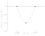
- FIG. 2 is a view showing a first hardness distribution of a cross section of a special metal strand used in the wire rope of the first embodiment
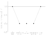
- FIG. 3 is a view showing a second hardness distribution of a cross section of the special metal strand used in the wire rope of the first embodiment.
- a wire rope 1 includes a core wire 3 (corresponding to a “special metal element wire” of the present invention) located at the center and six side wires 5 (5 a, 5 b, 5) wound around the core wire 3. 5c, 5d, 5e and 5f).
- the core wire 3 is a metal wire with a circular cross section that extends from the distal end to the proximal end of the center of the wire rope 1.
- the material of the core wire 3 is not specifically limited, In this embodiment, stainless steel is used.
- the hardness of the outer peripheral part in a cross section is higher than the hardness of the center part in a cross section. That is, only the surface of the core wire 3 is cured, and the inside of the core wire 3 is not cured. As a result, the flexibility of the core wire 3 was maintained, and the wear resistance due to contact with the side wire 5 could be improved.
- the conventionally well-known manufacturing methods such as swaging and dice drawing, can be utilized.
- the structure which hardens only the surface of the core wire 3 and does not harden the inside of the core wire 3 is, for example, as shown in FIG. 2, the hardness of the core wire 3 is secondary from the center of the cross section of the wire rope 1 toward the outer periphery.
- the hardness in FIGS. 2 and 3 indicates the Vickers hardness measured with a Vickers hardness meter, and the unit is “HV”.
- the hardness of the core wire 3 is about 650 HV at the cross-sectional center of the wire rope 1 and about 700 HV at the outer periphery, and the difference is 50 HV.
- the hardness of the core wire 3 is flat at about 650 HV in the vicinity of the center portion of the wire rope 1, is about 700 HV at the outer periphery, and the difference is 50 HV.
- the side wires 5 are metal strands having a circular cross section that are spirally wound around the core wire 3 in the longitudinal direction.
- the material of the side wires 5 is not particularly limited, but in this embodiment, stainless steel is used, and other tungsten can be used. .
- the core wire 3 in which the hardness of the outer peripheral portion in the cross section is higher than the hardness of the central portion is arranged at the center of the wire rope 1, and a plurality of side wires 5 (5a, 5b, 5c, 5d). 5e and 5f) are all in contact with the core wire 3, so that the durability of the wire rope can be improved.
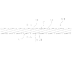
- FIG. 4 is a side view of the wire rope of the second embodiment
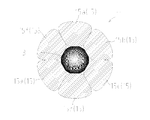
- FIG. 5 is a cross-sectional view taken along the line AA of FIG.
- the wire rope 11 includes a core wire 3 positioned at the center and six side wires 15 (15a, 15b, 15c, 15d, 15e and 15f) wound around the core wire 3. I have.
- the side wires 15 (15a, 15b, 15c, 15d, 15e, and 15f) are deformed and substantially trapezoidal metal strands that are spirally wound around the core wire 3 in the longitudinal direction.
- the material of the side wire 15 (15a, 15b, 15c, 15d, 15e and 15f) is not particularly limited, but in this embodiment, stainless steel is used, and other tungsten can be used. .
- the core wire 3 in which the hardness of the outer peripheral portion in the cross section is higher than the hardness of the central portion is disposed at the center of the wire rope 1, and the six side wires 15 having a substantially trapezoidal cross section.
- the six side wires 15 having a substantially trapezoidal cross section.
- FIG. 6 is a side view of the wire rope of the third embodiment
- FIG. 7 is a cross-sectional view taken along the line BB of FIG.
- the wire rope 101 includes a core wire rope 11 according to the second embodiment and six side wire ropes 21, 31 wound around the core wire rope 11, which are located at the center. 41, 51, 61 and 71.
- the side wire ropes 21, 31, 41, 51, 61 and 71 are stranded wires having the same configuration as the core wire rope 11, each wound spirally around the core wire rope 11 in the longitudinal direction. is there.
- the side wire rope 21 includes a core wire 3a (corresponding to the “special metal element wire” of the present invention) located at the center and six side wires 25 (25a, 25b, 25c) wound around the core wire 3a. 25d, 25e, and 25f), and the side wire rope 31 includes a core wire 3b located at the center (corresponding to the “special metal strand” of the present invention) and six wires wound around the core wire 3b.
- Side wire 35 35a, 35b, 35c, 35d, 35e and 35f
- the side wire rope 41 is a core wire 3c (corresponding to the “special metal strand” of the present invention) located in the center, and the core wire 3c.
- six side lines 45 45a, 45b, 45c, 45d, 45e, and 45f wound around.
- the side wire rope 51 includes a core wire 3d (corresponding to the “special metal element wire” of the present invention) located at the center and six side wires 55 (55a, 55b, 55c) wound around the core wire 3d. , 55d, 55e, and 55f), and the side wire rope 61 has a core wire 3e (corresponding to the “special metal element wire” of the present invention) located at the center and six wires wound around the core wire 3e.
- Side wire 65 (65a, 65b, 65c, 65d, 65e and 65f)
- the side wire rope 71 is a core wire 3f located at the center (corresponding to the “special metal strand” of the present invention), and the core wire 3f.
- six side lines 75 75a, 75b, 75c, 75d, 75e and 75f wound around.
- the core wire whose outer peripheral portion has a hardness higher than that of the central portion in the cross section is arranged at the center, and all six side lines having a substantially trapezoidal cross section are in surface contact with the core wire. Since the wire rope 101 is formed by twisting a plurality of wire ropes having a substantially circular cross-sectional outer periphery, the torque transferability of the wire rope 101 (when one end of the wire rope is rotated, Torque transmission at the other end of the wire rope can be further improved, and the durability of the wire rope can be further improved.
- FIG. 8 is a cross-sectional view of the wire rope of the fourth embodiment.
- the wire rope 81 is wound around the core stranded wire 13 located at the center, the four side wires 82 arranged outside the core stranded wire 13, and the core stranded wire 13 and the side wires 82. And eight side lines 85.
- the core strand 13 is composed of four metal strands (13a, 13b, 13c, and 13d (corresponding to the “special metal strand” of the present invention)), and each metal strand has a circular cross section.
- the material of the metal strands (13a, 13b, 13c and 13d) is not particularly limited, but stainless steel is used in the present embodiment.
- each metal strand (13a, 13b, 13c, and 13d) which comprises the core strand wire 13 the hardness of the outer peripheral part in a cross section is higher than the hardness of the center part in a cross section. That is, each metal strand (13a, 13b, 13c, and 13d) has a structure in which only the surface of the metal strand is cured and the inside of the metal strand is not cured. And the core strand 13 is comprised by twisting four this metal strand. Thereby, the softness
- the four side wires 82 (82a, 82b, 82c and 82d) are arranged outside the core twisted wire 13 and are thinner than the metal strands (13a, 13b, 13c and 13d) constituting the core twisted wire 13. It is composed of a metal wire having a diameter and has a circular cross section.
- the material of the side line 82 (82a, 82b, 82c, and 82d) is not specifically limited, In this embodiment, stainless steel is used.
- the eight side wires 85 are arranged outside the core twisted wire 13 and the side wires 82 (82a, 82b, 82c and 82d) and have a circular cross section. This is a metal wire.
- the material of the side line 85 is not specifically limited, In this embodiment, stainless steel is used.
- the core stranded wire 13 in which four metal strands in which the hardness of the outer peripheral portion in the cross section is higher than the hardness of the central portion is arranged at the center of the wire rope 81.
- the flexibility of the wire rope 81 can be further improved, and the durability can be improved.
- FIG. 9 is a cross-sectional view of the wire rope of the fifth embodiment.
- the wire rope 91 is wound around the core stranded wire 23 located at the center, the four side wires 92 arranged outside the core stranded wire 23, and the core stranded wire 23 and the side wires 92. Eight side lines 95 are provided.
- the core stranded wire 23 is composed of four metal strands (23a, 23b, 23c, and 23d (corresponding to the “special metal strand” of the present invention)), and each metal strand is circular in cross section.
- the material of the metal strands (23a, 23b, 23c, and 23d) is not particularly limited, but stainless steel is used in the present embodiment.
- the hardness of the outer peripheral portion in the cross section of the metal strand 23d is higher than the hardness of the central portion in the cross section. . That is, the metal strand 23d has a structure in which only the surface of the metal strand is cured and the inside of the metal strand is not cured. On the other hand, the metal strands 23a, 23b and 23c have a substantially constant hardness throughout the cross section.
- the core stranded wire 23 is formed by twisting four metal strands. Thereby, the flexibility of the core twisted wire 23 can be further improved.
- the four side wires 92 are arranged outside the core twisted wire 23 and are thinner than the metal strands (23a, 23b, 23c and 23d) constituting the core twisted wire 23. It is composed of a metal wire having a diameter and has a circular cross section.
- the material of the side line 92 is not specifically limited, In this embodiment, stainless steel is used.
- the eight side wires 95 are arranged outside the core twisted wire 23 and the side wires 92 (92a, 92b, 92c and 92d) and have a circular cross section. This is a metal wire.
- the material of the side line 95 is not specifically limited, In this embodiment, stainless steel is used.
- the core stranded wire 23 using the metal strand in which the hardness of the outer peripheral portion in the cross section is higher than the hardness of the central portion is disposed at the center of the wire rope 91.
- the flexibility of 91 can be improved and the durability can be improved.
- the side line 5, the side line 15, the side line 25, the side line 35, the side line 45, the side line 55, the side line 65, and the side line 75 are formed by six metal strands.
- the number of metal strands is not limited to six and may be three or more.
- the core strand 13 and the core strand 23 are formed by twisting four metal strands, but the number of metal strands is limited to four. It is not necessary to have more than one.
- the side wire 85 and the side wire 95 were 8 metal strands
- the number of metal strands is not limited to 8, The core strand wire 13 or a core strand It is sufficient if the number is configured to cover the line 23.
Landscapes
- Ropes Or Cables (AREA)
Abstract
Description
(第1実施形態)
図1は、本発明の第1実施形態のワイヤロープの断面図であり、図2は、第1実施形態のワイヤロープに使用する特殊金属素線断面の第1の硬度分布を示す図であり、図3は、第1実施形態のワイヤロープに使用する特殊金属素線断面の第2の硬度分布を示す図である。
以下、本発明の第2実施形態を説明するが、第1実施形態と共通する部分については説明を省略し、図中では同じ符号を付することとする。
図4は、第2実施形態のワイヤロープの側面図であり、図5は、図4のA-A断面図である。
以下、本発明の第3実施形態を説明するが、第1実施形態と共通する部分については説明を省略し、図中では同じ符号を付することとする。
図6は、第3実施形態のワイヤロープの側面図であり、図7は、図6のB-B断面図である。
以下、第4実施形態を説明する。図8は、第4実施形態のワイヤロープの断面図である。
以下、第5実施形態を説明する。図9は、第5実施形態のワイヤロープの断面図である。
一方、金属素線23a、23b及び23cは、断面全体における硬度が略一定である。
3・・・芯線
13,23・・・芯撚線
5,15,25,35,45,55,65,75,82,85,92,95・・・側線
Claims (6)
- 複数の金属素線を巻回して形成されたワイヤーロープにおいて、
前記複数の金属素線の内、少なくとも1本の特殊金属素線は、その断面における外周の硬度が、その断面における中心の硬度よりも高いことを特徴とするワイヤーロープ。 - 前記特殊金属素線を中心に配置したことを特徴とする請求項1に記載のワイヤーロープ。
- 前記複数の金属素線は、前記特殊金属素線と、その特殊金属素線に接触する複数の側金属素線のみからなることを特徴とする請求項2に記載のワイヤーロープ。
- 前記特殊金属素線の断面を円形とし、前記複数の側金属素線の断面を略台形状としたことを特徴とする請求項3に記載のワイヤーロープ。
- 請求項4に記載のワイヤロープを複数本撚って形成したことを特徴とするワイヤーロープ。
- 複数の前記特殊金属素線を撚った撚線を中心に配置したことを特徴とする請求項1に記載のワイヤーロープ。
Priority Applications (6)
| Application Number | Priority Date | Filing Date | Title |
|---|---|---|---|
| PCT/JP2016/063945 WO2017195284A1 (ja) | 2016-05-11 | 2016-05-11 | ワイヤーロープ |
| KR1020177000910A KR102001319B1 (ko) | 2016-05-11 | 2016-05-11 | 와이어 로프 |
| EP16829223.3A EP3456876A4 (en) | 2016-05-11 | 2016-05-11 | METAL CABLE |
| CN201680001589.4A CN107923124A (zh) | 2016-05-11 | 2016-05-11 | 金属丝线 |
| JP2016563867A JP6344781B2 (ja) | 2016-05-11 | 2016-05-11 | ワイヤーロープ |
| US15/450,446 US20170328000A1 (en) | 2016-05-11 | 2017-03-06 | Wire rope |
Applications Claiming Priority (1)
| Application Number | Priority Date | Filing Date | Title |
|---|---|---|---|
| PCT/JP2016/063945 WO2017195284A1 (ja) | 2016-05-11 | 2016-05-11 | ワイヤーロープ |
Related Child Applications (1)
| Application Number | Title | Priority Date | Filing Date |
|---|---|---|---|
| US15/450,446 Continuation US20170328000A1 (en) | 2016-05-11 | 2017-03-06 | Wire rope |
Publications (1)
| Publication Number | Publication Date |
|---|---|
| WO2017195284A1 true WO2017195284A1 (ja) | 2017-11-16 |
Family
ID=60266520
Family Applications (1)
| Application Number | Title | Priority Date | Filing Date |
|---|---|---|---|
| PCT/JP2016/063945 Ceased WO2017195284A1 (ja) | 2016-05-11 | 2016-05-11 | ワイヤーロープ |
Country Status (6)
| Country | Link |
|---|---|
| US (1) | US20170328000A1 (ja) |
| EP (1) | EP3456876A4 (ja) |
| JP (1) | JP6344781B2 (ja) |
| KR (1) | KR102001319B1 (ja) |
| CN (1) | CN107923124A (ja) |
| WO (1) | WO2017195284A1 (ja) |
Cited By (3)
| Publication number | Priority date | Publication date | Assignee | Title |
|---|---|---|---|---|
| JP2019131942A (ja) * | 2018-01-26 | 2019-08-08 | 東京製綱株式会社 | フレキシブル・ウエイト・ワイヤロープ |
| JP2022505537A (ja) * | 2018-10-23 | 2022-01-14 | ベカルト アドバンスド コーズ アールテル エンベー | 鋼ワイヤロープ、被覆鋼ワイヤロープ及び鋼ワイヤロープを含むベルト |
| WO2023074567A1 (ja) * | 2021-10-27 | 2023-05-04 | 朝日インテック株式会社 | ワイヤーロープ |
Families Citing this family (2)
| Publication number | Priority date | Publication date | Assignee | Title |
|---|---|---|---|---|
| US11427959B2 (en) * | 2015-12-21 | 2022-08-30 | Nippon Sheet Glass Company, Limited | Rubber-reinforcing cord and rubber product using same |
| CN110538945B (zh) * | 2019-09-19 | 2021-04-13 | 中国人民解放军陆军装甲兵学院 | 一种难熔高熵合金绞股丝材、其应用及制备方法 |
Citations (8)
| Publication number | Priority date | Publication date | Assignee | Title |
|---|---|---|---|---|
| JPH06184965A (ja) * | 1992-12-18 | 1994-07-05 | Bridgestone Corp | スチールコード |
| JPH08144182A (ja) | 1994-11-15 | 1996-06-04 | Toyota Autom Loom Works Ltd | 撚り線ワイヤロープ及び織機における開口装置 |
| JPH08311788A (ja) * | 1995-05-16 | 1996-11-26 | Tokyo Seiko Co Ltd | ゴム補強用超高強度スチールワイヤおよびスチールコード |
| JPH11309509A (ja) * | 1998-04-24 | 1999-11-09 | Nippon Steel Corp | 捻回特性の優れた高強度極細鋼線およびその製造方法 |
| JP2000256792A (ja) * | 1999-03-04 | 2000-09-19 | Nippon Steel Corp | 高強度高延性極細鋼線及び撚り線並びにその製造方法 |
| JP2004124342A (ja) | 2002-10-04 | 2004-04-22 | Shuji Tarumoto | インナーワイヤーロープ |
| JP2004327254A (ja) | 2003-04-24 | 2004-11-18 | Fujikura Ltd | 高耐食鋼心アルミ撚線 |
| JP2015137428A (ja) * | 2014-01-20 | 2015-07-30 | 朝日インテック株式会社 | 撚線及びその撚線を用いたガイドワイヤ |
Family Cites Families (28)
| Publication number | Priority date | Publication date | Assignee | Title |
|---|---|---|---|---|
| JPS57195948A (en) * | 1981-05-29 | 1982-12-01 | Koichi Hamada | Wire rope |
| JPS6241387A (ja) * | 1985-08-15 | 1987-02-23 | 住友電気工業株式会社 | Pc用鋼撚線 |
| DE3632298A1 (de) * | 1986-09-23 | 1988-04-07 | Saar Gmbh Drahtseilwerk | Drahtseil fuer einen haengenden einsatz ueber eine grosse hoehendifferenz, insbesondere foerderkorbseil, tiefseeseil oder seilbahnseil |
| JPH0474840A (ja) * | 1990-07-18 | 1992-03-10 | Tokyo Tungsten Co Ltd | プリントワイヤおよびその製造方法 |
| JP3191839B2 (ja) * | 1993-06-14 | 2001-07-23 | 住友電気工業株式会社 | コントロールケーブル用インナーワイヤ及びその製造方法 |
| JP3096238B2 (ja) * | 1996-02-15 | 2000-10-10 | 神鋼鋼線工業株式会社 | ワイヤロープ |
| US6399886B1 (en) * | 1997-05-02 | 2002-06-04 | General Science & Technology Corp. | Multifilament drawn radiopaque high elastic cables and methods of making the same |
| DE69906194T2 (de) * | 1998-07-30 | 2004-01-29 | Aster Puteaux | Verbunddracht mit einem Kern aus Kohlenstoffstahl und einer Aussenschicht aus einem rostfreiem Stahl |
| JP2000096151A (ja) * | 1998-09-21 | 2000-04-04 | Nippon Koshuha Steel Co Ltd | 冷間剪断切断用の金属製線材または棒材の製造方法 |
| US6339920B1 (en) * | 1999-08-27 | 2002-01-22 | Kawasaki Steel Corporation | Rotation-resisting wire rope |
| US6327841B1 (en) * | 1999-11-16 | 2001-12-11 | Utilx Corporation | Wire rope lubrication |
| EP1230497B1 (en) * | 1999-11-16 | 2004-04-07 | Utilx Corporation | Wire rope lubrication |
| JP2002113541A (ja) * | 2000-10-10 | 2002-04-16 | Ykk Corp | 金属製線材及びその製造方法 |
| US7104299B2 (en) * | 2001-04-23 | 2006-09-12 | The Goodyear Tire & Rubber Company | Two piece tire with improved tire tread belt |
| KR100426059B1 (ko) * | 2001-12-26 | 2004-04-06 | 홍덕스틸코드주식회사 | 가공면이 우수한 소우 와이어 |
| US7093416B2 (en) * | 2004-06-17 | 2006-08-22 | 3M Innovative Properties Company | Cable and method of making the same |
| JP4804860B2 (ja) * | 2004-10-27 | 2011-11-02 | 古河電気工業株式会社 | 複合撚線導体 |
| US7458200B2 (en) * | 2005-12-08 | 2008-12-02 | The Goodyear Tire & Rubber Co. | High elongation cable |
| CN101016701B (zh) * | 2007-02-15 | 2012-01-11 | 孟凡英 | 耐磨割绳 |
| CN201351246Y (zh) * | 2009-01-21 | 2009-11-25 | 江苏宏泰不锈钢丝绳有限公司 | 无磁耐腐蚀不锈钢钢丝绳 |
| CA2798131C (en) * | 2010-04-30 | 2018-08-21 | Schlumberger Canada Limited | Polymer-bonded metallic elements used as strength members, and/or power or data carriers in oilfield cables |
| MX336981B (es) * | 2010-07-23 | 2016-02-09 | Schlumberger Technology Bv | Cable que tiene un miembro de resistencia con revestimientos de polimero termoadherido para crear un sistema de miembro de resistencia con camisa termoadherida continuamente. |
| EP2436808A1 (en) * | 2010-09-30 | 2012-04-04 | NV Bekaert SA | Multi-filament with annealed copper core and drawn steel layer |
| FR2991632B1 (fr) * | 2012-06-07 | 2014-06-27 | Michelin & Cie | Tringle hybride allegee pour pneumatique. |
| DE102012112911A1 (de) * | 2012-12-21 | 2014-06-26 | Casar Drahtseilwerk Saar Gmbh | Drahtseil sowie Verfahren und Vorrichtung zur Herstellung des Drahtseils |
| JP2014169507A (ja) * | 2013-03-01 | 2014-09-18 | Bridgestone Corp | ゴム物品補強用スチールワイヤおよびこれを用いたゴム物品 |
| US9428858B2 (en) * | 2013-03-15 | 2016-08-30 | 1735729 Alberta Ltd. | Wire rope and method of constructing wire rope |
| RU2543400C1 (ru) * | 2013-08-08 | 2015-02-27 | Общество С Ограниченной Ответственностью "Армастил" | Арматурный канат и способ его изготовления |
-
2016
- 2016-05-11 KR KR1020177000910A patent/KR102001319B1/ko active Active
- 2016-05-11 WO PCT/JP2016/063945 patent/WO2017195284A1/ja not_active Ceased
- 2016-05-11 CN CN201680001589.4A patent/CN107923124A/zh active Pending
- 2016-05-11 JP JP2016563867A patent/JP6344781B2/ja not_active Ceased
- 2016-05-11 EP EP16829223.3A patent/EP3456876A4/en not_active Withdrawn
-
2017
- 2017-03-06 US US15/450,446 patent/US20170328000A1/en not_active Abandoned
Patent Citations (8)
| Publication number | Priority date | Publication date | Assignee | Title |
|---|---|---|---|---|
| JPH06184965A (ja) * | 1992-12-18 | 1994-07-05 | Bridgestone Corp | スチールコード |
| JPH08144182A (ja) | 1994-11-15 | 1996-06-04 | Toyota Autom Loom Works Ltd | 撚り線ワイヤロープ及び織機における開口装置 |
| JPH08311788A (ja) * | 1995-05-16 | 1996-11-26 | Tokyo Seiko Co Ltd | ゴム補強用超高強度スチールワイヤおよびスチールコード |
| JPH11309509A (ja) * | 1998-04-24 | 1999-11-09 | Nippon Steel Corp | 捻回特性の優れた高強度極細鋼線およびその製造方法 |
| JP2000256792A (ja) * | 1999-03-04 | 2000-09-19 | Nippon Steel Corp | 高強度高延性極細鋼線及び撚り線並びにその製造方法 |
| JP2004124342A (ja) | 2002-10-04 | 2004-04-22 | Shuji Tarumoto | インナーワイヤーロープ |
| JP2004327254A (ja) | 2003-04-24 | 2004-11-18 | Fujikura Ltd | 高耐食鋼心アルミ撚線 |
| JP2015137428A (ja) * | 2014-01-20 | 2015-07-30 | 朝日インテック株式会社 | 撚線及びその撚線を用いたガイドワイヤ |
Non-Patent Citations (1)
| Title |
|---|
| See also references of EP3456876A4 |
Cited By (7)
| Publication number | Priority date | Publication date | Assignee | Title |
|---|---|---|---|---|
| JP2019131942A (ja) * | 2018-01-26 | 2019-08-08 | 東京製綱株式会社 | フレキシブル・ウエイト・ワイヤロープ |
| JP7304160B2 (ja) | 2018-01-26 | 2023-07-06 | 東京製綱株式会社 | フレキシブル・ウエイト・ワイヤロープ |
| JP2022505537A (ja) * | 2018-10-23 | 2022-01-14 | ベカルト アドバンスド コーズ アールテル エンベー | 鋼ワイヤロープ、被覆鋼ワイヤロープ及び鋼ワイヤロープを含むベルト |
| JP7500554B2 (ja) | 2018-10-23 | 2024-06-17 | ベカルト アドバンスド コーズ アールテル エンベー | 鋼ワイヤロープ、被覆鋼ワイヤロープ及び鋼ワイヤロープを含むベルト |
| WO2023074567A1 (ja) * | 2021-10-27 | 2023-05-04 | 朝日インテック株式会社 | ワイヤーロープ |
| JP2023064965A (ja) * | 2021-10-27 | 2023-05-12 | 朝日インテック株式会社 | ワイヤーロープ |
| JP7846513B2 (ja) | 2021-10-27 | 2026-04-15 | 朝日インテック株式会社 | ワイヤーロープ |
Also Published As
| Publication number | Publication date |
|---|---|
| CN107923124A (zh) | 2018-04-17 |
| EP3456876A4 (en) | 2019-11-20 |
| KR102001319B1 (ko) | 2019-07-17 |
| US20170328000A1 (en) | 2017-11-16 |
| JP6344781B2 (ja) | 2018-06-20 |
| EP3456876A1 (en) | 2019-03-20 |
| JPWO2017195284A1 (ja) | 2018-06-07 |
| KR20170141181A (ko) | 2017-12-22 |
Similar Documents
| Publication | Publication Date | Title |
|---|---|---|
| JP6344781B2 (ja) | ワイヤーロープ | |
| JP6631979B2 (ja) | ワイヤーロープ | |
| US2241955A (en) | Metallic rope and cable | |
| JP6329695B1 (ja) | 多層体、多層中空体及び多層中空体を備えたカテーテル | |
| US4809492A (en) | Torsionally balanced wire rope or cable | |
| JP6548772B2 (ja) | 難自転性ワイヤロープ | |
| DE102014105753A1 (de) | Seil | |
| JP7138251B2 (ja) | ワイヤロープ | |
| JP6424296B2 (ja) | エレベータ用ワイヤロープ | |
| US3729921A (en) | Non-rotating rope with spiral strands | |
| JP4913654B2 (ja) | 圧縮導体 | |
| JP5855305B1 (ja) | 弾性クローラ | |
| US1927477A (en) | Machinery packing | |
| JP2016011481A (ja) | 難自転性ワイヤロープ | |
| JP6176792B2 (ja) | ワイヤーロープ | |
| KR100336475B1 (ko) | 합성 수지가 피복된 코어 스트랜드 구조의 기계 작동용와이어 케이블 | |
| JP2605688Y2 (ja) | 光ファイバ内蔵型架空地線 | |
| JP2023501540A5 (ja) | ||
| JP2640563B2 (ja) | 引っ張りワイヤロープ | |
| JPS609987A (ja) | ワイヤロ−プおよびその製造方法 | |
| KR200435622Y1 (ko) | 매트리스 구조물 | |
| JP2017040335A (ja) | コントロールケーブル | |
| JPH02165508A (ja) | 低コロナ低風騒音電線 | |
| JP2021188211A (ja) | ワイヤロープ | |
| JPH1031914A (ja) | 捻回補正溝付ケーブル |
Legal Events
| Date | Code | Title | Description |
|---|---|---|---|
| ENP | Entry into the national phase |
Ref document number: 2016563867 Country of ref document: JP Kind code of ref document: A |
|
| ENP | Entry into the national phase |
Ref document number: 20177000910 Country of ref document: KR Kind code of ref document: A |
|
| REEP | Request for entry into the european phase |
Ref document number: 2016829223 Country of ref document: EP |
|
| WWE | Wipo information: entry into national phase |
Ref document number: 2016829223 Country of ref document: EP |
|
| 121 | Ep: the epo has been informed by wipo that ep was designated in this application |
Ref document number: 16829223 Country of ref document: EP Kind code of ref document: A1 |
|
| NENP | Non-entry into the national phase |
Ref country code: DE |