WO2017199633A1 - Lentille d'imagerie et dispositif d'imagerie - Google Patents
Lentille d'imagerie et dispositif d'imagerie Download PDFInfo
- Publication number
- WO2017199633A1 WO2017199633A1 PCT/JP2017/014504 JP2017014504W WO2017199633A1 WO 2017199633 A1 WO2017199633 A1 WO 2017199633A1 JP 2017014504 W JP2017014504 W JP 2017014504W WO 2017199633 A1 WO2017199633 A1 WO 2017199633A1
- Authority
- WO
- WIPO (PCT)
- Prior art keywords
- lens
- imaging
- optical axis
- vicinity
- refractive power
- Prior art date
- Legal status (The legal status is an assumption and is not a legal conclusion. Google has not performed a legal analysis and makes no representation as to the accuracy of the status listed.)
- Ceased
Links
Images
















Classifications
-
- G—PHYSICS
- G02—OPTICS
- G02B—OPTICAL ELEMENTS, SYSTEMS OR APPARATUS
- G02B13/00—Optical objectives specially designed for the purposes specified below
- G02B13/001—Miniaturised objectives for electronic devices, e.g. portable telephones, webcams, PDAs, small digital cameras
- G02B13/0015—Miniaturised objectives for electronic devices, e.g. portable telephones, webcams, PDAs, small digital cameras characterised by the lens design
- G02B13/002—Miniaturised objectives for electronic devices, e.g. portable telephones, webcams, PDAs, small digital cameras characterised by the lens design having at least one aspherical surface
- G02B13/0045—Miniaturised objectives for electronic devices, e.g. portable telephones, webcams, PDAs, small digital cameras characterised by the lens design having at least one aspherical surface having five or more lenses
-
- G—PHYSICS
- G02—OPTICS
- G02B—OPTICAL ELEMENTS, SYSTEMS OR APPARATUS
- G02B27/00—Optical systems or apparatus not provided for by any of the groups G02B1/00 - G02B26/00, G02B30/00
- G02B27/0025—Optical systems or apparatus not provided for by any of the groups G02B1/00 - G02B26/00, G02B30/00 for optical correction, e.g. distorsion, aberration
-
- G—PHYSICS
- G02—OPTICS
- G02B—OPTICAL ELEMENTS, SYSTEMS OR APPARATUS
- G02B9/00—Optical objectives characterised both by the number of the components and their arrangements according to their sign, i.e. + or -
- G02B9/64—Optical objectives characterised both by the number of the components and their arrangements according to their sign, i.e. + or - having more than six components
Definitions
- the present disclosure relates to an imaging lens that forms an optical image of a subject on an imaging element such as a CCD (Charge Coupled Device) or a CMOS (Complementary Metal Oxide Semiconductor), and a digital still camera that performs shooting by mounting the imaging lens.
- an imaging apparatus such as a mobile phone with a camera and an information mobile terminal.
- Digital still cameras are becoming thinner year by year, such as card types, and there is a demand for smaller imaging devices. Also in mobile phones, downsizing of the imaging device is required in order to reduce the thickness of the terminal itself and to secure a space for mounting multiple functions. As a result, there is an increasing demand for further downsizing the imaging lens mounted on the imaging device.
- the number of pixels has been increased by making the pixel pitch of the image sensor finer, and accordingly, the imaging lenses used in these imaging devices have been required to have high performance. ing.
- a first imaging lens includes, in order from the object side to the image plane side, a meniscus-shaped first lens in which the shape in the vicinity of the optical axis has a convex surface facing the object side, and the optical axis
- a second lens having a positive refractive power with a convex surface facing the object side in the vicinity
- a third lens having a negative refractive power in the vicinity of the optical axis
- a fourth lens a fifth lens
- a positive lens in the vicinity of the optical axis and a seventh lens having a negative refractive power in the vicinity of the optical axis and an aspherical surface having an inflection point on the image side lens surface. It is.
- a first imaging device includes an imaging lens and an imaging element that outputs an imaging signal corresponding to an optical image formed by the imaging lens. This is constituted by a first imaging lens according to an embodiment.
- a second imaging lens includes, in order from the object side to the image plane side, a first lens, a second lens having a positive refractive power in the vicinity of the optical axis, and the vicinity of the optical axis
- the lens surface on the surface side is composed of an aspherical seventh lens having an inflection point, and satisfies the following conditional expression. -0.5 ⁇ f / f1 ⁇ 0.23 (1) However, f: Focal length of the entire lens system f1: The focal length of the first lens.
- a second imaging device includes an imaging lens and an imaging element that outputs an imaging signal corresponding to an optical image formed by the imaging lens. This is constituted by the second imaging lens according to one embodiment.
- the configuration of each lens is optimized with a configuration of seven lenses as a whole. .
- the configuration of the seven lenses as a whole is optimized, and the configuration of each lens is optimized. Therefore, it is possible to correct various aberrations satisfactorily while reducing the size, and to reduce image quality deterioration due to unnecessary light.
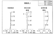
- FIG. 3 is an aberration diagram showing various aberrations in Numerical Example 1 in which specific numerical values are applied to the imaging lens illustrated in FIG. 1. It is a lens sectional view showing the 2nd example of composition of an imaging lens.
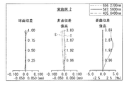
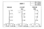
- FIG. 4 is an aberration diagram showing various aberrations in Numerical Example 2 in which specific numerical values are applied to the imaging lens illustrated in FIG. 3. It is a lens sectional view showing the 3rd example of composition of an imaging lens.
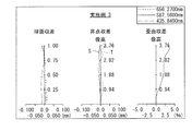
- FIG. 6 is an aberration diagram showing various aberrations in Numerical Example 3 in which specific numerical values are applied to the imaging lens illustrated in FIG. 5. It is lens sectional drawing which shows the 4th structural example of an imaging lens.
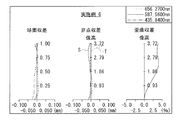
- FIG. 10 is an aberration diagram illustrating various aberrations in Numerical Example 4 in which specific numerical values are applied to the imaging lens illustrated in FIG. 7. It is a lens sectional view showing the 5th example of composition of an imaging lens.
- FIG. 10 is an aberration diagram illustrating various aberrations in Numerical Example 5 in which specific numerical values are applied to the imaging lens illustrated in FIG. 9. It is a lens sectional view showing the 6th example of composition of an imaging lens.
- FIG. 12 is an aberration diagram illustrating various aberrations in Numerical Example 6 in which specific numerical values are applied to the imaging lens illustrated in FIG. 11. It is a lens sectional view showing the 7th example of composition of an imaging lens.
- FIG. 10 is an aberration diagram illustrating various aberrations in Numerical Example 4 in which specific numerical values are applied to the imaging lens illustrated in FIG. 7. It is a lens sectional view showing the 5th example of composition of an imaging lens.
- FIG. 10 is an aberration diagram illustrating various aberrations in Numerical Example 5 in which
- FIG. 14 is an aberration diagram illustrating various aberrations in Numerical Example 7 in which specific numerical values are applied to the imaging lens illustrated in FIG. 13. It is lens sectional drawing which shows the 8th structural example of an imaging lens.
- FIG. 16 is an aberration diagram illustrating various aberrations in Numerical Example 8 in which specific numerical values are applied to the imaging lens illustrated in FIG. 15. It is lens sectional drawing which shows the 9th structural example of an imaging lens.
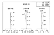
- FIG. 18 is an aberration diagram illustrating various aberrations in Numerical Example 9 in which specific numerical values are applied to the imaging lens illustrated in FIG. 17. It is lens sectional drawing which shows the 10th structural example of an imaging lens.
- FIG. 16 is an aberration diagram illustrating various aberrations in Numerical Example 8 in which specific numerical values are applied to the imaging lens illustrated in FIG. 15. It is lens sectional drawing which shows the 9th structural example of an imaging lens.
- FIG. 18 is an aberration diagram illustrating various aberrations in Numerical Example 9 in which specific numerical values are applied to the imaging
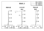
- FIG. 20 is an aberration diagram illustrating various aberrations in Numerical Example 10 in which specific numerical values are applied to the imaging lens illustrated in FIG. 19. It is a lens sectional view showing the 11th example of composition of an imaging lens.
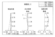
- FIG. 22 is an aberration diagram illustrating various aberrations in Numerical Example 11 in which specific numerical values are applied to the imaging lens illustrated in FIG. 21. It is a lens sectional view showing the 12th example of composition of an imaging lens.
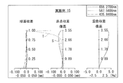
- FIG. 24 is an aberration diagram illustrating various aberrations in Numerical Example 12 in which specific numerical values are applied to the imaging lens illustrated in FIG. 23. It is a lens sectional view showing the 13th example of composition of an imaging lens.
- FIG. 22 is an aberration diagram illustrating various aberrations in Numerical Example 11 in which specific numerical values are applied to the imaging lens illustrated in FIG. 21.
- FIG. 24 is an aberration diagram illustrating various aberrations in Numerical Example 12 in which specific numerical values are applied to the imaging lens illustrated in FIG. 23. It is
- FIG. 26 is an aberration diagram illustrating various aberrations in Numerical Example 13 in which specific numerical values are applied to the imaging lens illustrated in FIG. 25. It is a lens sectional view showing the 14th example of composition of an imaging lens.
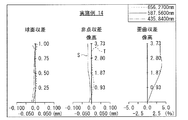
- FIG. 28 is an aberration diagram illustrating various aberrations in Numerical Example 14 in which specific numerical values are applied to the imaging lens illustrated in FIG. 27. It is a lens sectional view showing the 15th example of composition of an imaging lens.
- FIG. 30 is an aberration diagram illustrating various aberrations in Numerical Example 15 in which specific numerical values are applied to the imaging lens illustrated in FIG. 29. It is a lens sectional view showing the 16th example of composition of an imaging lens.
- FIG. 28 is an aberration diagram illustrating various aberrations in Numerical Example 14 in which specific numerical values are applied to the imaging lens illustrated in FIG. 27.
- FIG. 30 is an aberration diagram illustrating various aberrations in Numerical Example 15 in which specific numerical values are applied to the imaging lens illustrated in FIG. 29. It
- FIG. 32 is an aberration diagram showing various aberrations in Numerical Example 16 in which specific numerical values are applied to the imaging lens illustrated in FIG. 31. It is a lens sectional view showing the 17th example of composition of an imaging lens.
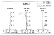
- FIG. 34 is an aberration diagram showing various aberrations in Numerical Example 17 in which specific numerical values are applied to the imaging lens illustrated in FIG. 33. It is a lens sectional view showing the 18th example of composition of an imaging lens.
- FIG. 36 is an aberration diagram showing various aberrations in Numerical Example 18 in which specific numerical values are applied to the imaging lens illustrated in FIG. 35. It is a lens sectional view showing the 19th example of composition of an imaging lens.
- FIG. 34 is an aberration diagram showing various aberrations in Numerical Example 17 in which specific numerical values are applied to the imaging lens illustrated in FIG. 33.
- FIG. 36 is an aberration diagram showing various aberrations in Numerical Example 18 in which specific numerical values are applied to the imaging lens illustrated in FIG. 35.
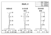
- FIG. 38 is an aberration diagram showing various aberrations in Numerical Example 19 in which specific numerical values are applied to the imaging lens illustrated in FIG. 37. It is sectional drawing which shows the generation
- a first lens, a positive second lens, a third lens, a fourth lens, a fifth lens, and a sixth lens are sequentially arranged from the object side to the image plane side.
- a bright lens composed of a lens and a seventh lens has been proposed.
- a configured lens having a brightness of about F1.6 has been proposed.
- the imaging lens disclosed in Patent Document 1 has been proposed to have a large aperture and a bright lens, the shape of the lens surface on the object side of the first lens is concave on the object side, or the first lens is biconvex, thereby shortening the overall length.
- the ratio of the maximum image height to the total length is 1.7 or more.
- the seven-lens imaging lens described in Patent Document 2 has a bright F1.6 lens, but the ratio of the maximum image height to the total length is 1.8 or more.
- the imaging lenses described in Patent Document 1 and Patent Document 2 have room for improvement in reducing the optical length while maintaining performance with a large aperture. Further, when the imaging lens is reduced in height, the distance between the optical surface and the imaging surface is shortened, so that reflected light easily enters the imaging surface from the optical surface, and the tendency for ghosts and flares to occur becomes significant. In particular, when the F-number of the imaging lens is reduced in response to the demand for a large aperture of the lens in relation to high performance, the effective diameter of the lens increases, and the diameter of the light shielding member increases accordingly, The risk of increased ghosts and flares increases.
- an imaging lens and an imaging apparatus that can effectively correct various aberrations by efficiently suppressing ghosts and flares while having a small size and a large aperture.
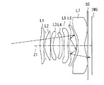
- FIG. 1 illustrates a first configuration example of an imaging lens according to an embodiment of the present disclosure.
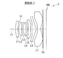
- FIG. 3 shows a second configuration example of the imaging lens.
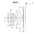
- FIG. 5 shows a third configuration example of the imaging lens.
- FIG. 7 shows a fourth configuration example of the imaging lens.
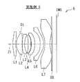
- FIG. 9 shows a fifth configuration example of the imaging lens.
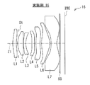
- FIG. 11 shows a sixth configuration example of the imaging lens.
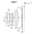
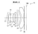
- FIG. 13 shows a seventh configuration example of the imaging lens.
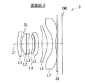
- FIG. 15 shows an eighth configuration example of the imaging lens.
- FIG. 17 shows a ninth configuration example of the imaging lens.
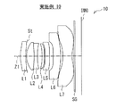
- FIG. 19 shows a tenth configuration example of the imaging lens.
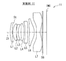
- FIG. 21 shows an eleventh configuration example of the imaging lens.
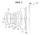
- FIG. 23 shows a twelfth configuration example of the imaging lens.
- FIG. 1 illustrates a first configuration example of an imaging lens according to an embodiment of the present disclosure.
- FIG. 3 shows a second configuration example of the imaging lens.
- FIG. 5 shows a third
- FIG. 25 shows a thirteenth configuration example of the imaging lens.
- FIG. 27 shows a fourteenth configuration example of the imaging lens.
- FIG. 29 shows a fifteenth configuration example of the imaging lens.
- FIG. 31 shows a sixteenth configuration example of the imaging lens.
- FIG. 33 shows a seventeenth configuration example of the imaging lens.
- FIG. 35 shows an eighteenth configuration example of the imaging lens.
- FIG. 37 shows a nineteenth configuration example of the imaging lens. Numerical examples in which specific numerical values are applied to these configuration examples will be described later.
- symbol IMG indicates an image plane
- Z1 indicates an optical axis.
- St indicates an aperture stop.
- An imaging element 101 such as a CCD or a CMOS may be disposed in the vicinity of the image plane IMG.
- optical members such as a sealing glass SG for protecting the imaging element and various optical filters may be arranged.
- the configuration of the imaging lens according to the present embodiment will be described in association with the configuration example illustrated in FIG. 1 and the like as appropriate, but the technology according to the present disclosure is not limited to the illustrated configuration example.
- the imaging lens according to the present embodiment includes a first lens L1, a second lens L2, a third lens L3, and a fourth lens L4 in order from the object side to the image plane side along the optical axis Z1.
- the fifth lens L5, the sixth lens L6, and the seventh lens L7 are substantially composed of seven lenses.
- the first lens L1 has a meniscus shape in which the shape in the vicinity of the optical axis is convex toward the object side.
- the first lens L1 desirably has a positive or negative refractive power in the vicinity of the optical axis.
- the second lens L2 has a convex surface facing the object side in the vicinity of the optical axis.
- the second lens L2 desirably has a positive refractive power in the vicinity of the optical axis.
- the third lens L3 has a negative refractive power in the vicinity of the optical axis.
- the fourth lens L4 has a positive or negative refractive power in the vicinity of the optical axis.
- the fifth lens L5 has a positive or negative refractive power in the vicinity of the optical axis.
- the sixth lens L6 has a positive refractive power in the vicinity of the optical axis.
- the seventh lens L7 has a negative refractive power in the vicinity of the optical axis.
- the seventh lens L7 has an aspherical shape having an inflection point in which the concave-convex shape changes midway as the lens surface on the image plane side moves from the center to the periphery, and other than the intersection with the optical axis Z1. It is desirable to have at least one inflection point. More specifically, the image surface side lens surface of the seventh lens L7 is preferably an aspherical surface having a concave shape in the vicinity of the optical axis and a peripheral portion having a convex shape.
- the imaging lens according to the present embodiment further satisfies a predetermined conditional expression described later.
- the imaging lens according to the present embodiment has a seven-lens configuration as a whole, and the configuration of each lens is optimized, so that various aberrations can be corrected satisfactorily even though it is small and has a large aperture. In addition, image quality deterioration due to unnecessary light such as ghost and flare can be reduced.
- the aspherical surface in which the lens surface closest to the image plane has a concave shape in the vicinity of the optical axis and the peripheral portion has a convex shape.
- the imaging lens according to the present embodiment desirably satisfies the following conditional expression (1). -0.5 ⁇ f / f1 ⁇ 0.23 (1)
- f Focal length of the entire lens system
- f1 A focal length of the first lens L1.
- the conditional expression (1) defines the ratio between the focal length of the first lens L1 and the focal length of the entire lens system.
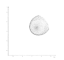
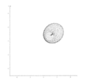
- FIG. 39 shows an example of a generation path of baying and glare generated by inter-surface reflection of the first lens L1.
- FIG. 40 shows the shape of baying and glare generated by the inter-surface reflection of the first lens L1 in the imaging lens 1 according to the first configuration example of FIG. The relative intensity of the baling glare at this time is 1.
- the positive refractive power of the first lens L1 becomes too strong.
- the object-side lens surface of the first lens L1. A part of the light beam incident on the surface is reflected by the lens surface on the image plane side of the first lens L1, and further reflected by the lens surface on the object side, and then forms an image near the image plane.
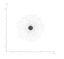
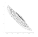
- strong baying glare having a relative intensity of about 3.9 collected on the arc is generated.
- a part of the luminous flux near the principal ray out of the luminous flux incident on the first lens L1 is the lens surface on the image plane side of the first lens L1.
- the light is reflected from the surface, and further reflected from the lens surface on the object side, and then the image is formed near the image plane.
- strong bailing glare having a condensed relative intensity of about 24.4 occurs.
- conditional expression (1) In order to better realize the effect of the conditional expression (1), it is more desirable to set the numerical range of the conditional expression (1) as the following conditional expression (1) ′. -0.20 ⁇ f / f1 ⁇ 0.20 (1) '
- conditional expression (1) In order to realize the effect of the conditional expression (1) more satisfactorily, it is more desirable to set the numerical range of the conditional expression (1) as the following conditional expression (1) ′′. -0.074 ⁇ f / f1 ⁇ 0.092 (1) ''
- conditional expression (1) '' the object-side lens surface and the image-side lens surface of the first lens L1, and the object-side lens of the second lens L2 Regardless of whether the surface is concave or convex in the vicinity of the optical axis, baying and glare can be reduced and good resolution performance can be ensured despite the large aperture.
- the imaging lens according to the present embodiment further satisfies the following conditional expressions (2) and (3).
- ⁇ max (L1R1) Maximum value of the surface angle ⁇ (L1R1) of the lens surface on the object side of the first lens L1 within the effective diameter R (L3R2): The radius of curvature of the lens surface on the image plane side of the third lens L3 .
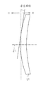
- FIG. 49 shows an example of the surface angle ⁇ (L1R1) of the lens surface on the object side of the first lens L1.
- the surface angle ⁇ (L1R1) is positive when the lens surface is inclined toward the image plane side and negative when the lens surface is inclined toward the object side.
- the unit is “degree”. The same applies to the surface angles of other lens surfaces in other conditional expressions described later.
- conditional expression (2) defines the maximum inclination angle of the lens surface on the object side of the first lens L1.
- Conditional expression (3) defines the ratio between the curvature of the lens surface on the image plane side of the third lens L3 and the focal length of the entire lens system.
- FIG. 43 shows a baying glare generated by total reflection on the image surface side lens surface of the third lens L3 and surface reflection on the object side lens surface of the first lens L1 and then reaching the image surface IMG. An example of the generation path of is shown.
- conditional expression (2) In order to better realize the effect of the conditional expression (2), it is more desirable to set the numerical range of the conditional expression (2) as the following conditional expression (2) ′. 5 ⁇ max (L1R1) ⁇ 18 (2) ′
- the imaging lens according to the present embodiment further satisfies the following conditional expressions (4) and (5).
- ⁇ max (L6R1) The maximum value of the surface angle ⁇ (L6R1) of the lens surface on the object side of the sixth lens L6 within 30% of the effective diameter (positive when the lens surface is inclined toward the image surface side, the unit being "Every time")
- ⁇ min (L6R1) the minimum value of the surface angle ⁇ (L6R1) of the lens surface on the object side of the sixth lens L6 within 30% of the effective diameter (positive when the lens surface is inclined toward the image surface side, the unit being "Every time”
- ⁇ max (L6R2) the maximum value of the surface angle ⁇ (L6R2) of the lens surface on the image surface side of the sixth lens L6 within the diameter of 70% of
- the conditional expression (4) defines the range of the maximum value of the surface angle ⁇ (L6R1) of the object-side lens surface of the sixth lens L6 within 30% of the effective diameter.
- FIG. 45 shows an example of a generation path of baying and glare generated by inter-surface reflection of the sixth lens L6.
- the conditional expression (5) defines the range of the maximum value of the surface angle ⁇ (L6R2) of the lens surface on the image surface side of the sixth lens L6 within the diameter of 70% of the effective diameter. Satisfactory conditional expression (5) can ensure good performance. If ⁇ max (L6R2) exceeds the upper limit value of conditional expression (5), the convex power of the lens surface on the image plane side of the sixth lens L6 is insufficient and the correction power for off-axis coma is insufficient, resulting in poor image quality. It will cause deterioration. When ⁇ max (L6R2) falls below the lower limit value of the conditional expression (5), for example, as shown in FIG.
- a part of the off-axis light beam reflected on the lens surface on the image plane side of the sixth lens L6 is the first.
- the sixth lens L6 is totally reflected without being emitted from the object-side lens surface, and is repeatedly totally reflected in the sixth lens L6, and then emitted from the lens surface on the image surface side of the sixth lens L6 to the image surface IMG. To reach.
- strong concentrated baying glare is generated as shown in FIG. 46, for example.
- conditional expression (4) it is more desirable to set the numerical range of the conditional expression (4) as the following conditional expression (4) ′. ⁇ 10 ⁇ min (L6R1) ⁇ max (L6R1) ⁇ 8 (4) ′
- conditional expression (4) In order to realize the effect of the conditional expression (4) more satisfactorily, it is more desirable to set the numerical range of the conditional expression (4) as the following conditional expression (4) ′′. ⁇ 6 ⁇ max (L6R1) ⁇ 7 (4) ′′
- conditional expression (5) it is more desirable to set the numerical range of the conditional expression (5) as the following conditional expression (5) ′. ⁇ 22 ⁇ min (L6R2) ⁇ max (L6R2) ⁇ 8 (5) ′
- the imaging lens according to the present embodiment further satisfies the following conditional expression (6).
- ⁇ max (L3R2) the maximum value of the surface angle ⁇ (L3R2) of the lens surface on the image surface side of the third lens L3 within the effective diameter (positive when the lens surface is inclined toward the image surface side, the unit is “degree”)
- ⁇ max (L3R2) the maximum value of the surface angle ⁇ (L3R2) of the lens surface on the image surface side of the third lens L3 within the effective diameter (positive when the lens surface is inclined toward the image surface side, the unit is “degree”)
- the conditional expression (6) defines the range of the maximum value of the surface angle ⁇ (L3R2) of the lens surface on the image surface side of the third lens L3 within the effective diameter. Satisfying conditional expression (6) can ensure good performance.
- ⁇ max (L3R2) falls below the lower limit value of conditional expression (6), the negative refractive power of the third lens L3 becomes weak, and spherical aberration and coma generated in the first lens L1 or the second lens L2 are corrected well. It becomes difficult. If ⁇ max (L3R2) exceeds the upper limit value of conditional expression (6), the third lens L3 has excessive negative power, making it difficult to correct spherical aberration and coma aberration, and the surface angle is too large. This increases the manufacturing difficulty.
- conditional expression (6) In order to better realize the effect of the conditional expression (6), it is more desirable to set the numerical range of the conditional expression (6) as the following conditional expression (6) ′. 15 ⁇ (L3R2) ⁇ 38 (6) ′
- the imaging lens according to the present embodiment further satisfies the following conditional expression (7).
- f Focal length of the entire lens system
- f12 The combined focal length of the first lens L1 and the second lens L2.
- conditional expression (7) defines the ratio between the combined focal length of the first lens L1 and the second lens L2 and the focal length of the entire lens system. Satisfying conditional expression (7) can ensure good performance. If f12 / f falls below the lower limit value of conditional expression (7), the combined power of the first lens L1 and the second lens L2 becomes too strong, making it difficult to correct spherical aberration, coma aberration, and astigmatism. . If f12 / f exceeds the upper limit value of conditional expression (7), the combined power of the first lens L1 and the second lens L2 becomes too weak, making it difficult to shorten the optical total length.
- conditional expression (7) it is more desirable to set the numerical range of the conditional expression (7) as the following conditional expression (7) ′. 0.5 ⁇ f12 / f ⁇ 1.5 (7) ′
- the imaging lens according to the present embodiment further satisfies the following conditional expression (8). ⁇ 5 ⁇ f3 / f ⁇ 0.5 (8)
- f Focal length of the entire lens system
- f3 The focal length of the third lens L3.
- conditional expression (8) defines the ratio between the focal length of the third lens L3 and the focal length of the entire lens system. Satisfying conditional expression (8) can ensure good performance.
- f3 / f falls below the lower limit value of conditional expression (8), the negative refractive power of the third lens L3 becomes weak, and it is difficult to satisfactorily correct the longitudinal chromatic aberration generated in the positive second lens L2.
- f3 / f exceeds the upper limit value of conditional expression (8), the negative refractive power of the third lens L3 becomes too strong, making it difficult to shorten the optical total length.
- conditional expression (8) it is more desirable to set the numerical range of the conditional expression (8) as the following conditional expression (8) ′. -3.5 ⁇ f3 / f ⁇ -1.0 (8) '
- the imaging lens according to the present embodiment further satisfies the following conditional expression (9). 0.023 ⁇ T (L3) / f ⁇ 0.15 (9)
- f Focal length of the entire lens system
- T (L3) The center thickness of the third lens L3.
- the conditional expression (9) defines the ratio between the center thickness of the third lens L3 and the focal length of the entire lens system.
- the third lens L3 has a concave meniscus shape, although the coma aberration can be easily corrected by reducing the center thickness, the lens moldability becomes difficult.
- T (L3) / f within the range of conditional expression (9), the coma aberration is kept good, and molding becomes easy.
- conditional expression (9) it is more desirable to set the numerical range of the conditional expression (9) as the following conditional expression (9) ′. 0.045 ⁇ T (L3) / f ⁇ 0.1 (9) ′
- the imaging lens according to the present embodiment further satisfies the following conditional expression (10).
- the imaging lens according to the present embodiment further satisfies the following conditional expressions (11) and (12).
- ⁇ d (L3) Abbe number of the third lens L3 with respect to the d-line
- ⁇ d (L5) Abbe number of the fifth lens L5 with respect to the d-line.
- conditional expression (10) defines the Abbe number for the d-line of the glass material of the first lens L1.
- the conditional expressions (11) and (12) define the Abbe numbers with respect to the d-line of the glass material of the third lens L3 and the fifth lens L5, respectively.
- the imaging lens according to the present embodiment further satisfies the following conditional expressions (13), (14), and (15).
- ⁇ d (L7) Abbe number of the seventh lens L7 with respect to the d line.
- Conditional expressions (13), (14), and (15) respectively define the Abbe numbers for the d-line of the glass material of the fourth lens L4, the sixth lens L6, and the seventh lens L7.
- conditional expressions (13), (14), and (15) it is possible to ensure good performance with a low profile.
- the Abbe numbers of the sixth lens L6 and the seventh lens L7 exceed the lower limit values of the conditional expressions (13), (14), and (15), the effect of correcting chromatic aberration can be enhanced.
- This configuration example is an example of a mobile terminal device (for example, a mobile information terminal or a mobile phone terminal) provided with an imaging device.
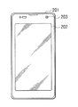
- This portable terminal device includes a substantially rectangular casing 201.
- a display unit 202 and a front camera unit 203 are provided on the front side of the housing 201 (FIG. 47).
- a main camera unit 204 and a camera flash 205 are provided on the back side of the housing 201 (FIG. 48).
- the display unit 202 is a touch panel that enables various operations, for example, by detecting a contact state with the surface. Accordingly, the display unit 202 has a display function for displaying various types of information and an input function for enabling various input operations by the user.
- the display unit 202 displays various data such as an operation state and an image captured by the front camera unit 203 or the main camera unit 204.
- the imaging lens according to the present embodiment can be applied as a camera module lens of an imaging device (front camera unit 203 or main camera unit 204) in a portable terminal device as shown in FIGS. 47 and 48, for example.
- a CCD that outputs an imaging signal (image signal) corresponding to an optical image formed by the imaging lens near the image plane IMG of the imaging lens
- An image sensor 101 such as a CMOS is disposed.
- an optical member such as a sealing glass SG for protecting the image sensor and various optical filters may be disposed between the seventh lens L7 and the image plane IMG.
- optical members such as the seal glass SG and various optical filters may be disposed at any position as long as they are between the seventh lens L7 and the image plane IMG.
- the imaging lens according to the present embodiment is not limited to the above-described portable terminal device, but can also be applied as an imaging lens for other electronic devices such as a digital still camera and a digital video camera.
- the present invention can be applied to general small-sized imaging devices using a solid-state imaging device such as a CCD or CMOS, for example, an optical sensor, a portable module camera, and a WEB camera. It can also be applied to surveillance cameras and the like.
- Si indicates the number of the i-th surface with a sign so as to increase sequentially from the most object side.
- Ri indicates the value (mm) of the paraxial radius of curvature of the i-th surface.
- Di indicates the value (mm) of the distance on the optical axis between the i-th surface and the i + 1-th surface.
- Ndi indicates the value of the refractive index at the d-line (wavelength 587.6 nm) of the material of the optical element having the i-th surface.
- ⁇ di indicates the value of the Abbe number in the d-line of the material of the optical element having the i-th surface.
- the part where the value of “Ri” is “ ⁇ ” indicates a plane or a virtual plane.
- “Li” indicates a surface attribute.
- the surface marked “OBJ” in “Li” indicates the object surface.
- L1R1 indicates the object-side lens surface of the first lens L1
- L1R2 indicates the image-side lens surface of the first lens L1.
- L2R1 indicates the object-side lens surface of the second lens L2
- “L2R2” indicates the image-side lens surface of the second lens L2. The same applies to other lens surfaces.
- the surface marked “ASP” in “Si” indicates an aspherical surface.
- the aspherical shape is defined by the following equation.
- E ⁇ i represents an exponential expression with a base of 10, that is, “10 ⁇ i ”.
- 0.12345E-05 represents “ 0.12345 ⁇ 10 ⁇ 5 ”.
- All of the imaging lenses 1 to 19 to which the following numerical examples are applied have a configuration satisfying the basic configuration of the lens described above. That is, all of the imaging lenses 1 to 19 are in order from the object side to the image plane side, the first lens L1, the second lens L2, the third lens L3, the fourth lens L4, and the fifth lens L5. And the sixth lens L6 and the seventh lens L7 are substantially composed of seven lenses.
- the first lens L1 has a meniscus shape in which the shape in the vicinity of the optical axis is convex toward the object side.
- the second lens L2 has a convex surface facing the object side in the vicinity of the optical axis.
- the seventh lens L7 has an aspherical shape in which the lens surface on the image side has an inflection point at which the uneven shape changes in the middle from the center to the periphery.
- the aperture stop St is disposed between the image surface side lens surface of the first lens L1 and the image surface side lens surface of the second lens L2.
- a seal glass SG is disposed between the seventh lens L7 and the image plane IMG.
- both surfaces of each of the first lens L1 to the seventh lens L7 are aspherical.
- [Table 2] and [Table 3] show values of coefficients representing the shape of the aspheric surfaces.
- the first lens L1 has a positive refractive power in the vicinity of the optical axis.
- the second lens L2 has a positive refractive power in the vicinity of the optical axis.
- the third lens L3 has a negative refractive power in the vicinity of the optical axis.
- the fourth lens L4 has a positive refractive power in the vicinity of the optical axis.
- the fifth lens L5 has a negative refractive power in the vicinity of the optical axis.
- the sixth lens L6 has a positive refractive power in the vicinity of the optical axis.
- the seventh lens L7 has a negative refractive power in the vicinity of the optical axis.
- FIG. 2 shows spherical aberration, astigmatism (field curvature), and distortion as various aberrations.
- Each of these aberration diagrams shows aberrations with the d-line (587.56 nm) as a reference wavelength.
- the spherical aberration diagram also shows aberrations with respect to g-line (435.84 nm) and C-line (656.27 nm).
- a solid line (S) indicates a value on a sagittal image plane
- T indicates a value on a tangential image plane.
- the imaging lens 1 according to Numerical Example 1 has a good optical performance with various aberrations corrected satisfactorily even though it is small.
- both surfaces of each of the first lens L1 to the seventh lens L7 are aspherical.
- [Table 5] and [Table 6] show coefficient values representing the shape of the aspheric surfaces.
- the first lens L1 has a positive refractive power in the vicinity of the optical axis.
- the second lens L2 has a positive refractive power in the vicinity of the optical axis.
- the third lens L3 has a negative refractive power in the vicinity of the optical axis.
- the fourth lens L4 has a positive refractive power in the vicinity of the optical axis.
- the fifth lens L5 has a negative refractive power in the vicinity of the optical axis.
- the sixth lens L6 has a positive refractive power in the vicinity of the optical axis.
- the seventh lens L7 has a negative refractive power in the vicinity of the optical axis.
- both surfaces of each of the first lens L1 to the seventh lens L7 are aspherical.
- [Table 8] and [Table 9] show coefficient values representing the shape of the aspheric surfaces.
- the first lens L1 has a negative refractive power in the vicinity of the optical axis.
- the second lens L2 has a positive refractive power in the vicinity of the optical axis.
- the third lens L3 has a negative refractive power in the vicinity of the optical axis.
- the fourth lens L4 has a negative refractive power in the vicinity of the optical axis.
- the fifth lens L5 has a positive refractive power in the vicinity of the optical axis.
- the sixth lens L6 has a positive refractive power in the vicinity of the optical axis.
- the seventh lens L7 has a negative refractive power in the vicinity of the optical axis.
- both surfaces of each of the first lens L1 to the seventh lens L7 are aspherical.
- [Table 11] and [Table 12] show values of coefficients representing the shape of the aspheric surfaces.
- the first lens L1 has a positive refractive power in the vicinity of the optical axis.
- the second lens L2 has a positive refractive power in the vicinity of the optical axis.
- the third lens L3 has a negative refractive power in the vicinity of the optical axis.
- the fourth lens L4 has a positive refractive power in the vicinity of the optical axis.
- the fifth lens L5 has a negative refractive power in the vicinity of the optical axis.
- the sixth lens L6 has a positive refractive power in the vicinity of the optical axis.
- the seventh lens L7 has a negative refractive power in the vicinity of the optical axis.
- Table 13 shows basic lens data of Numerical Example 5 in which specific numerical values are applied to the imaging lens 5 shown in FIG.
- both surfaces of each of the first lens L1 to the seventh lens L7 are aspherical.
- [Table 14] and [Table 15] show values of coefficients representing the shape of the aspheric surfaces.
- the first lens L1 has a positive refractive power in the vicinity of the optical axis.
- the second lens L2 has a positive refractive power in the vicinity of the optical axis.
- the third lens L3 has a negative refractive power in the vicinity of the optical axis.
- the fourth lens L4 has a negative refractive power in the vicinity of the optical axis.
- the fifth lens L5 has a negative refractive power in the vicinity of the optical axis.
- the sixth lens L6 has a positive refractive power in the vicinity of the optical axis.
- the seventh lens L7 has a negative refractive power in the vicinity of the optical axis.
- both surfaces of each of the first lens L1 to the seventh lens L7 are aspherical.
- [Table 17] and [Table 18] show values of coefficients representing the shape of the aspheric surfaces.
- the first lens L1 has a positive refractive power in the vicinity of the optical axis.
- the second lens L2 has a positive refractive power in the vicinity of the optical axis.
- the third lens L3 has a negative refractive power in the vicinity of the optical axis.
- the fourth lens L4 has a positive refractive power in the vicinity of the optical axis.
- the fifth lens L5 has a positive refractive power in the vicinity of the optical axis.
- the sixth lens L6 has a positive refractive power in the vicinity of the optical axis.
- the seventh lens L7 has a negative refractive power in the vicinity of the optical axis.
- Table 19 shows basic lens data of Numerical Example 7 in which specific numerical values are applied to the imaging lens 7 shown in FIG.
- both surfaces of each of the first lens L1 to the seventh lens L7 are aspherical.
- [Table 20] and [Table 21] show coefficient values representing the shape of the aspheric surfaces.
- the first lens L1 has a positive refractive power in the vicinity of the optical axis.
- the second lens L2 has a positive refractive power in the vicinity of the optical axis.
- the third lens L3 has a negative refractive power in the vicinity of the optical axis.
- the fourth lens L4 has a positive refractive power in the vicinity of the optical axis.
- the fifth lens L5 has a positive refractive power in the vicinity of the optical axis.
- the sixth lens L6 has a positive refractive power in the vicinity of the optical axis.
- the seventh lens L7 has a negative refractive power in the vicinity of the optical axis.
- both surfaces of each of the first lens L1 to the seventh lens L7 are aspherical.
- [Table 23] and [Table 24] show values of coefficients representing the shape of the aspheric surfaces.
- the first lens L1 has a positive refractive power in the vicinity of the optical axis.
- the second lens L2 has a positive refractive power in the vicinity of the optical axis.
- the third lens L3 has a negative refractive power in the vicinity of the optical axis.
- the fourth lens L4 has a negative refractive power in the vicinity of the optical axis.
- the fifth lens L5 has a negative refractive power in the vicinity of the optical axis.
- the sixth lens L6 has a positive refractive power in the vicinity of the optical axis.
- the seventh lens L7 has a negative refractive power in the vicinity of the optical axis.
- Table 25 shows basic lens data of Numerical Example 9 in which specific numerical values are applied to the imaging lens 9 shown in FIG.
- both surfaces of each of the first lens L1 to the seventh lens L7 are aspherical.
- [Table 26] and [Table 27] show coefficient values representing the shape of the aspheric surfaces.
- the first lens L1 has a positive refractive power in the vicinity of the optical axis.
- the second lens L2 has a positive refractive power in the vicinity of the optical axis.
- the third lens L3 has a negative refractive power in the vicinity of the optical axis.
- the fourth lens L4 has a positive refractive power in the vicinity of the optical axis.
- the fifth lens L5 has a negative refractive power in the vicinity of the optical axis.
- the sixth lens L6 has a positive refractive power in the vicinity of the optical axis.
- the seventh lens L7 has a negative refractive power in the vicinity of the optical axis.
- Table 28 shows basic lens data of Numerical Example 10 in which specific numerical values are applied to the imaging lens 10 shown in FIG.
- both surfaces of each of the first lens L1 to the seventh lens L7 are aspherical.
- [Table 29] and [Table 30] show coefficient values representing the shape of the aspheric surfaces.
- the first lens L1 has a positive refractive power in the vicinity of the optical axis.
- the second lens L2 has a positive refractive power in the vicinity of the optical axis.
- the third lens L3 has a negative refractive power in the vicinity of the optical axis.
- the fourth lens L4 has a negative refractive power in the vicinity of the optical axis.
- the fifth lens L5 has a negative refractive power in the vicinity of the optical axis.
- the sixth lens L6 has a positive refractive power in the vicinity of the optical axis.
- the seventh lens L7 has a negative refractive power in the vicinity of the optical axis.
- both surfaces of each of the first lens L1 to the seventh lens L7 are aspherical.
- [Table 32] and [Table 33] show coefficient values representing the shape of the aspheric surfaces.
- the first lens L1 has a positive refractive power in the vicinity of the optical axis.
- the second lens L2 has a positive refractive power in the vicinity of the optical axis.
- the third lens L3 has a negative refractive power in the vicinity of the optical axis.
- the fourth lens L4 has a positive refractive power in the vicinity of the optical axis.
- the fifth lens L5 has a negative refractive power in the vicinity of the optical axis.
- the sixth lens L6 has a positive refractive power in the vicinity of the optical axis.
- the seventh lens L7 has a negative refractive power in the vicinity of the optical axis.
- Table 34 shows basic lens data of Numerical Example 12 in which specific numerical values are applied to the imaging lens 12 shown in FIG.
- both surfaces of the first lens L1 to the seventh lens L7 are aspherical.
- [Table 35] and [Table 36] show coefficient values representing the shape of the aspheric surfaces.
- the first lens L1 has a positive refractive power in the vicinity of the optical axis.
- the second lens L2 has a positive refractive power in the vicinity of the optical axis.
- the third lens L3 has a negative refractive power in the vicinity of the optical axis.
- the fourth lens L4 has a positive refractive power in the vicinity of the optical axis.
- the fifth lens L5 has a positive refractive power in the vicinity of the optical axis.
- the sixth lens L6 has a positive refractive power in the vicinity of the optical axis.
- the seventh lens L7 has a negative refractive power in the vicinity of the optical axis.
- Table 37 shows basic lens data of Numerical Example 13 in which specific numerical values are applied to the imaging lens 13 shown in FIG.
- both surfaces of each of the first lens L1 to the seventh lens L7 are aspherical.
- [Table 38] and [Table 39] show coefficient values representing the shape of the aspheric surfaces.
- the first lens L1 has a positive refractive power in the vicinity of the optical axis.
- the second lens L2 has a positive refractive power in the vicinity of the optical axis.
- the third lens L3 has a negative refractive power in the vicinity of the optical axis.
- the fourth lens L4 has a positive refractive power in the vicinity of the optical axis.
- the fifth lens L5 has a negative refractive power in the vicinity of the optical axis.
- the sixth lens L6 has a positive refractive power in the vicinity of the optical axis.
- the seventh lens L7 has a negative refractive power in the vicinity of the optical axis.
- both surfaces of each of the first lens L1 to the seventh lens L7 are aspherical.
- [Table 41] and [Table 42] show values of coefficients representing the shape of the aspheric surfaces.
- the first lens L1 has a positive refractive power in the vicinity of the optical axis.
- the second lens L2 has a positive refractive power in the vicinity of the optical axis.
- the third lens L3 has a negative refractive power in the vicinity of the optical axis.
- the fourth lens L4 has a negative refractive power in the vicinity of the optical axis.
- the fifth lens L5 has a negative refractive power in the vicinity of the optical axis.
- the sixth lens L6 has a positive refractive power in the vicinity of the optical axis.
- the seventh lens L7 has a negative refractive power in the vicinity of the optical axis.
- both surfaces of each of the first lens L1 to the seventh lens L7 are aspherical.
- [Table 44] and [Table 45] show coefficient values representing the shape of the aspheric surfaces.
- the first lens L1 has a positive refractive power in the vicinity of the optical axis.
- the second lens L2 has a positive refractive power in the vicinity of the optical axis.
- the third lens L3 has a negative refractive power in the vicinity of the optical axis.
- the fourth lens L4 has a positive refractive power in the vicinity of the optical axis.
- the fifth lens L5 has a negative refractive power in the vicinity of the optical axis.
- the sixth lens L6 has a positive refractive power in the vicinity of the optical axis.
- the seventh lens L7 has a negative refractive power in the vicinity of the optical axis.
- Table 46 shows basic lens data of Numerical Example 16 in which specific numerical values are applied to the imaging lens 16 shown in FIG.
- both surfaces of each of the first lens L1 to the seventh lens L7 are aspherical.
- [Table 47] and [Table 48] show coefficient values representing the shape of the aspheric surfaces.
- the first lens L1 has a positive refractive power in the vicinity of the optical axis.
- the second lens L2 has a positive refractive power in the vicinity of the optical axis.
- the third lens L3 has a negative refractive power in the vicinity of the optical axis.
- the fourth lens L4 has a negative refractive power in the vicinity of the optical axis.
- the fifth lens L5 has a negative refractive power in the vicinity of the optical axis.
- the sixth lens L6 has a positive refractive power in the vicinity of the optical axis.
- the seventh lens L7 has a negative refractive power in the vicinity of the optical axis.
- Table 49 shows basic lens data of Numerical Example 17 in which specific numerical values are applied to the imaging lens 17 shown in FIG.
- both surfaces of each of the first lens L1 to the seventh lens L7 are aspherical.
- [Table 50] and [Table 51] show values of coefficients representing the shape of the aspheric surfaces.
- the first lens L1 has a positive refractive power in the vicinity of the optical axis.
- the second lens L2 has a positive refractive power in the vicinity of the optical axis.
- the third lens L3 has a negative refractive power in the vicinity of the optical axis.
- the fourth lens L4 has a positive refractive power in the vicinity of the optical axis.
- the fifth lens L5 has a negative refractive power in the vicinity of the optical axis.
- the sixth lens L6 has a positive refractive power in the vicinity of the optical axis.
- the seventh lens L7 has a negative refractive power in the vicinity of the optical axis.
- both surfaces of each of the first lens L1 to the seventh lens L7 are aspherical.
- [Table 53] and [Table 54] show coefficient values representing the shape of the aspheric surfaces.
- the first lens L1 has a positive refractive power in the vicinity of the optical axis.
- the second lens L2 has a positive refractive power in the vicinity of the optical axis.
- the third lens L3 has a negative refractive power in the vicinity of the optical axis.
- the fourth lens L4 has a positive refractive power in the vicinity of the optical axis.
- the fifth lens L5 has a negative refractive power in the vicinity of the optical axis.
- the sixth lens L6 has a positive refractive power in the vicinity of the optical axis.
- the seventh lens L7 has a negative refractive power in the vicinity of the optical axis.
- Table 55 shows basic lens data of Numerical Example 19 in which specific numerical values are applied to the imaging lens 19 shown in FIG.
- both surfaces of each of the first lens L1 to the seventh lens L7 are aspheric.
- [Table 56] and [Table 57] show coefficient values representing the shape of the aspheric surfaces.
- the first lens L1 has a positive refractive power in the vicinity of the optical axis.
- the second lens L2 has a positive refractive power in the vicinity of the optical axis.
- the third lens L3 has a negative refractive power in the vicinity of the optical axis.
- the fourth lens L4 has a negative refractive power in the vicinity of the optical axis.
- the fifth lens L5 has a negative refractive power in the vicinity of the optical axis.
- the sixth lens L6 has a positive refractive power in the vicinity of the optical axis.
- the seventh lens L7 has a negative refractive power in the vicinity of the optical axis.
- [Table 59] and [Table 60] show values relating to the above-described conditional expressions, which are summarized for each numerical example. Note that Example 18 is out of the range of conditional expression (2).
- the configuration including substantially seven lenses has been described.
- the configuration may further include a lens having substantially no refractive power.
- this technique can take the following composition.
- a first lens having a meniscus shape in which the shape near the optical axis has a convex surface facing the object side;
- a second lens having a positive refractive power with a convex surface facing the object side in the vicinity of the optical axis;
- a third lens having negative refractive power in the vicinity of the optical axis;
- a sixth lens having a positive refractive power in the vicinity of the optical axis;
- An imaging lens comprising: a seventh lens having a negative refractive power in the vicinity of the optical axis and having an aspherical shape with an inflection point on the lens surface on the image plane side.
- ⁇ max (L6R1) Maximum value of the surface angle of the object side lens surface of the sixth lens within 30% of the effective diameter (positive when the lens surface is tilted to the image surface side, the unit is “degree”)
- ⁇ min (L6R1) Minimum value of the surface angle of the object side lens surface of the sixth lens within 30% of the effective diameter (positive when the lens surface is tilted toward the image surface side, the unit is “degrees”)
- ⁇ min (L6R2) Minimum value of the surface angle of the sixth lens surface on the image surface side within 70% of the effective diameter (positive when the lens surface is inclined toward the image surface surface surface side
- f focal length of the entire lens system
- f3 the focal length of the third lens.
- f Focal length of the entire lens system T (L3): The center thickness of the third lens.
- a first lens In order from the object side to the image plane side, A first lens; A second lens having a positive refractive power in the vicinity of the optical axis; A third lens having negative refractive power in the vicinity of the optical axis; A fourth lens; A fifth lens; A sixth lens having a positive refractive power in the vicinity of the optical axis; An imaging lens that has a negative refractive power in the vicinity of the optical axis and has an aspherical shape with an inflection point on the lens surface on the image plane side, and satisfies the following conditional expression. -0.5 ⁇ f / f1 ⁇ 0.23 (1) However, f: focal length of the entire lens system f1: a focal length of the first lens.
- ⁇ max (L6R1) Maximum value of the surface angle of the object side lens surface of the sixth lens within 30% of the effective diameter (positive when the lens surface is tilted to the image surface side, the unit is “degree”)
- ⁇ min (L6R1) Minimum value of the surface angle of the object side lens surface of the sixth lens within 30% of the effective diameter (positive when the lens surface is tilted toward the image surface side, the unit is “degrees”)
- ⁇ min (L6R2) Minimum value of the surface angle of the sixth lens surface on the image surface side within 70% of the effective diameter (positive when the lens surface is inclined toward the image surface surface surface side
- f focal length of the entire lens system
- f3 the focal length of the third lens.
- f Focal length of the entire lens system T (L3): The center thickness of the third lens.
- the imaging lens is In order from the object side to the image plane side, A first lens having a meniscus shape in which the shape near the optical axis has a convex surface facing the object side; A second lens having a positive refractive power with a convex surface facing the object side in the vicinity of the optical axis; A third lens having negative refractive power in the vicinity of the optical axis; A fourth lens; A fifth lens; A sixth lens having a positive refractive power in the vicinity of the optical axis;
- An imaging apparatus comprising: a seventh lens having a negative refractive power in the vicinity of the optical axis and having an aspherical shape with an inflection point on the lens surface on the image plane side.
- the imaging lens is In order from the object side to the image plane side, A first lens; A second lens having a positive refractive power in the vicinity of the optical axis; A third lens having negative refractive power in the vicinity of the optical axis; A fourth lens; A fifth lens; A sixth lens having a positive refractive power in the vicinity of the optical axis;
- An imaging device that includes a seventh lens having a negative refractive power in the vicinity of the optical axis and an aspherical surface having an inflection point on the lens surface on the image plane side, and satisfies the following conditional expression.
- f focal length of the entire lens system
- f1 a focal length of the first lens.
Landscapes
- Physics & Mathematics (AREA)
- General Physics & Mathematics (AREA)
- Optics & Photonics (AREA)
- Lenses (AREA)
Abstract
L'invention se rapporte à une lentille d'imagerie qui comprend, dans l'ordre depuis le côté objet jusqu'au côté surface d'image : une première lentille en forme de ménisque où les environs de l'axe optique sont formés de façon à être convexes vers le côté objet ; une deuxième lentille ayant une réfringence positive et formée de manière à être convexe vers le côté objet dans les environs de l'axe optique ; une troisième lentille ayant une réfringence négative dans les environs de l'axe optique ; une quatrième lentille ; une cinquième lentille ; une sixième lentille ayant une réfringence positive dans les environs de l'axe optique ; et une septième lentille ayant une réfringence négative dans les environs de l'axe optique, la surface de lentille côté surface d'image de la septième lentille ayant une forme non sphérique qui présente un point d'inflexion.
Priority Applications (3)
| Application Number | Priority Date | Filing Date | Title |
|---|---|---|---|
| US16/080,393 US20190049700A1 (en) | 2016-05-19 | 2017-04-07 | Imaging lens and imaging apparatus |
| CN201780028665.5A CN109073862B (zh) | 2016-05-19 | 2017-04-07 | 成像透镜和成像装置 |
| JP2018518153A JPWO2017199633A1 (ja) | 2016-05-19 | 2017-04-07 | 撮像レンズおよび撮像装置 |
Applications Claiming Priority (2)
| Application Number | Priority Date | Filing Date | Title |
|---|---|---|---|
| JP2016-100377 | 2016-05-19 | ||
| JP2016100377 | 2016-05-19 |
Publications (1)
| Publication Number | Publication Date |
|---|---|
| WO2017199633A1 true WO2017199633A1 (fr) | 2017-11-23 |
Family
ID=60325097
Family Applications (1)
| Application Number | Title | Priority Date | Filing Date |
|---|---|---|---|
| PCT/JP2017/014504 Ceased WO2017199633A1 (fr) | 2016-05-19 | 2017-04-07 | Lentille d'imagerie et dispositif d'imagerie |
Country Status (5)
| Country | Link |
|---|---|
| US (1) | US20190049700A1 (fr) |
| JP (1) | JPWO2017199633A1 (fr) |
| CN (1) | CN109073862B (fr) |
| TW (1) | TW201809793A (fr) |
| WO (1) | WO2017199633A1 (fr) |
Cited By (25)
| Publication number | Priority date | Publication date | Assignee | Title |
|---|---|---|---|---|
| CN107966790A (zh) * | 2017-12-18 | 2018-04-27 | 瑞声科技(新加坡)有限公司 | 摄像光学镜头 |
| CN108089303A (zh) * | 2017-12-18 | 2018-05-29 | 瑞声科技(新加坡)有限公司 | 摄像光学镜头 |
| CN108089301A (zh) * | 2017-12-18 | 2018-05-29 | 瑞声科技(新加坡)有限公司 | 摄像光学镜头 |
| US10365460B2 (en) | 2017-06-16 | 2019-07-30 | Largan Precision Co., Ltd. | Photographing lens assembly, image capturing unit and electronic device |
| CN110221397A (zh) * | 2018-03-02 | 2019-09-10 | 大立光电股份有限公司 | 光学摄影镜组、取像装置及电子装置 |
| JP2019203990A (ja) * | 2018-05-23 | 2019-11-28 | カンタツ株式会社 | 撮像レンズ |
| KR20200010545A (ko) * | 2018-05-29 | 2020-01-30 | 삼성전기주식회사 | 촬상 광학계 |
| US10690886B2 (en) | 2017-06-30 | 2020-06-23 | Largan Precision Co., Ltd. | Imaging lens assembly, image capturing unit and electronic device |
| WO2020202965A1 (fr) * | 2019-03-29 | 2020-10-08 | ソニー株式会社 | Lentille d'imagerie et dispositif d'imagerie |
| US10852513B2 (en) | 2018-03-30 | 2020-12-01 | Largan Precision Co., Ltd. | Photographing optical lens system, image capturing unit and electronic device |
| KR20210008136A (ko) * | 2018-05-29 | 2021-01-20 | 삼성전기주식회사 | 촬상 광학계 |
| KR20210008131A (ko) * | 2018-05-29 | 2021-01-20 | 삼성전기주식회사 | 촬상 광학계 |
| JP2021009339A (ja) * | 2019-06-29 | 2021-01-28 | エーエーシー オプティックス ソリューションズ ピーティーイー リミテッド | 撮像光学レンズ |
| JP2021009286A (ja) * | 2019-06-30 | 2021-01-28 | エーエーシー テクノロジーズ ピーティーイー リミテッド | 撮像光学レンズ |
| TWI721904B (zh) * | 2020-06-10 | 2021-03-11 | 大立光電股份有限公司 | 影像擷取鏡片組、取像裝置及電子裝置 |
| US11016270B2 (en) | 2018-05-10 | 2021-05-25 | Largan Precision Co., Ltd. | Photographing optical lens assembly, imaging apparatus and electronic device |
| CN113495346A (zh) * | 2020-04-03 | 2021-10-12 | 东京晨美光学电子株式会社 | 摄像镜头 |
| WO2022124852A1 (fr) * | 2020-12-10 | 2022-06-16 | 엘지이노텍 주식회사 | Système optique et module de caméra le comprenant |
| JP2022121305A (ja) * | 2021-02-08 | 2022-08-19 | ジョウシュウシ レイテック オプトロニクス カンパニーリミテッド | 撮像レンズ |
| US11573408B2 (en) | 2017-02-18 | 2023-02-07 | Largan Precision Co., Ltd. | Image capturing optical system, imaging apparatus and electronic device |
| US11644647B2 (en) | 2018-05-29 | 2023-05-09 | Samsung Electro-Mechanics Co., Ltd. | Optical imaging system having seven lenses of various refractive powers |
| JP2023553445A (ja) * | 2020-12-10 | 2023-12-21 | エルジー イノテック カンパニー リミテッド | 光学系及びこれを含むカメラモジュール |
| US11860450B2 (en) | 2017-11-23 | 2024-01-02 | Largan Precision Co., Ltd. | Optical imaging lens assembly, image capturing unit and electronic device |
| US11971527B2 (en) | 2018-03-28 | 2024-04-30 | Largan Precision Co., Ltd. | Photographing optical lens system, imaging apparatus and electronic device |
| JP7610739B1 (ja) | 2023-09-18 | 2025-01-08 | エーエーシー オプティックス (ソシュウ) カンパニーリミテッド | 撮像光学レンズ |
Families Citing this family (14)
| Publication number | Priority date | Publication date | Assignee | Title |
|---|---|---|---|---|
| KR102080657B1 (ko) * | 2016-12-26 | 2020-02-24 | 삼성전기주식회사 | 촬상 광학계 |
| US11347030B2 (en) * | 2017-06-20 | 2022-05-31 | Apple Inc. | Imaging lens system |
| CN108037579B (zh) * | 2018-01-19 | 2020-05-22 | 浙江舜宇光学有限公司 | 光学成像镜头 |
| TWI663424B (zh) * | 2018-08-23 | 2019-06-21 | 大立光電股份有限公司 | 攝像透鏡系統、取像裝置及電子裝置 |
| TWI657282B (zh) * | 2018-09-05 | 2019-04-21 | 大立光電股份有限公司 | 取像透鏡系統、取像裝置及電子裝置 |
| TWI665488B (zh) * | 2018-12-26 | 2019-07-11 | 大立光電股份有限公司 | 攝影光學系統、取像裝置及電子裝置 |
| CN110398815B (zh) * | 2019-06-29 | 2021-09-21 | 瑞声光学解决方案私人有限公司 | 摄像光学镜头 |
| CN111983785B (zh) * | 2020-09-11 | 2025-02-14 | 江西晶超光学有限公司 | 光学成像系统、取像模组和电子装置 |
| CN112198630B (zh) * | 2020-10-23 | 2025-07-08 | 江西欧菲光学有限公司 | 光学系统、镜头模组和电子设备 |
| DE102021103587B4 (de) * | 2021-02-16 | 2022-09-29 | Carl Zeiss Ag | Kompaktes Teleobjektiv mit Materialien mit anomaler relativer Teildispersion, Kamera sowie mobiles Gerät |
| WO2022198561A1 (fr) * | 2021-03-25 | 2022-09-29 | 欧菲光集团股份有限公司 | Système optique, module de capture d'image et dispositif électronique |
| CN113552704B (zh) * | 2021-09-23 | 2022-01-11 | 江西晶超光学有限公司 | 光学系统、摄像模组及电子设备 |
| CN116482843B (zh) * | 2023-06-26 | 2023-11-14 | 江西联益光学有限公司 | 光学镜头 |
| CN116974031B (zh) * | 2023-08-09 | 2025-12-02 | 浙江舜宇光学有限公司 | 光学成像镜头 |
Citations (9)
| Publication number | Priority date | Publication date | Assignee | Title |
|---|---|---|---|---|
| JPH06324264A (ja) * | 1993-05-13 | 1994-11-25 | Nikon Corp | 広角レンズ |
| JP2012173299A (ja) * | 2011-02-17 | 2012-09-10 | Sony Corp | 撮像レンズおよび撮像装置 |
| JP2014115456A (ja) * | 2012-12-10 | 2014-06-26 | Fujifilm Corp | 撮像レンズおよび撮像レンズを備えた撮像装置 |
| JP2014145961A (ja) * | 2013-01-30 | 2014-08-14 | Kantatsu Co Ltd | 撮像レンズ |
| US20140226220A1 (en) * | 2012-08-13 | 2014-08-14 | Largan Precision Co., Ltd. | Image lens assembly system |
| JP2015072405A (ja) * | 2013-10-04 | 2015-04-16 | コニカミノルタ株式会社 | 撮像レンズ、撮像装置及び携帯端末 |
| JP2015072404A (ja) * | 2013-10-04 | 2015-04-16 | コニカミノルタ株式会社 | 撮像レンズ、撮像装置及び携帯端末 |
| JP2015072402A (ja) * | 2013-10-04 | 2015-04-16 | コニカミノルタ株式会社 | 撮像レンズ、撮像装置及び携帯端末 |
| JP2016095460A (ja) * | 2014-11-17 | 2016-05-26 | 富士フイルム株式会社 | 撮像レンズおよび撮像レンズを備えた撮像装置 |
Family Cites Families (11)
| Publication number | Priority date | Publication date | Assignee | Title |
|---|---|---|---|---|
| JPS61126515A (ja) * | 1984-11-26 | 1986-06-14 | Canon Inc | 可変焦点距離レンズ |
| JPS61129612A (ja) * | 1984-11-29 | 1986-06-17 | Konishiroku Photo Ind Co Ltd | 前群交換式変倍レンズ |
| US5528428A (en) * | 1991-11-13 | 1996-06-18 | Nikon Corporation | Compact wide-angle objective lens |
| KR100388917B1 (ko) * | 1995-12-08 | 2003-09-19 | 삼성테크윈 주식회사 | 사진렌즈광학계 |
| JPH1078554A (ja) * | 1996-09-05 | 1998-03-24 | Asahi Optical Co Ltd | カスケード走査光学系の調整機構 |
| US6195209B1 (en) * | 1999-05-04 | 2001-02-27 | U.S. Precision Lens Incorporated | Projection lenses having reduced lateral color for use with pixelized panels |
| US7773316B2 (en) * | 2003-01-16 | 2010-08-10 | Tessera International, Inc. | Optics for an extended depth of field |
| US8294999B2 (en) * | 2003-01-16 | 2012-10-23 | DigitalOptics Corporation International | Optics for an extended depth of field |
| CN101373261B (zh) * | 2007-08-22 | 2010-09-29 | 鸿富锦精密工业(深圳)有限公司 | 广角镜头及使用该广角镜头的车辆装置 |
| US7766509B1 (en) * | 2008-06-13 | 2010-08-03 | Lumec Inc. | Orientable lens for an LED fixture |
| TWI586998B (zh) * | 2015-08-11 | 2017-06-11 | 大立光電股份有限公司 | 攝像用光學系統、取像裝置及電子裝置 |
-
2017
- 2017-04-07 US US16/080,393 patent/US20190049700A1/en not_active Abandoned
- 2017-04-07 JP JP2018518153A patent/JPWO2017199633A1/ja not_active Abandoned
- 2017-04-07 WO PCT/JP2017/014504 patent/WO2017199633A1/fr not_active Ceased
- 2017-04-07 CN CN201780028665.5A patent/CN109073862B/zh active Active
- 2017-05-09 TW TW106115359A patent/TW201809793A/zh unknown
Patent Citations (9)
| Publication number | Priority date | Publication date | Assignee | Title |
|---|---|---|---|---|
| JPH06324264A (ja) * | 1993-05-13 | 1994-11-25 | Nikon Corp | 広角レンズ |
| JP2012173299A (ja) * | 2011-02-17 | 2012-09-10 | Sony Corp | 撮像レンズおよび撮像装置 |
| US20140226220A1 (en) * | 2012-08-13 | 2014-08-14 | Largan Precision Co., Ltd. | Image lens assembly system |
| JP2014115456A (ja) * | 2012-12-10 | 2014-06-26 | Fujifilm Corp | 撮像レンズおよび撮像レンズを備えた撮像装置 |
| JP2014145961A (ja) * | 2013-01-30 | 2014-08-14 | Kantatsu Co Ltd | 撮像レンズ |
| JP2015072405A (ja) * | 2013-10-04 | 2015-04-16 | コニカミノルタ株式会社 | 撮像レンズ、撮像装置及び携帯端末 |
| JP2015072404A (ja) * | 2013-10-04 | 2015-04-16 | コニカミノルタ株式会社 | 撮像レンズ、撮像装置及び携帯端末 |
| JP2015072402A (ja) * | 2013-10-04 | 2015-04-16 | コニカミノルタ株式会社 | 撮像レンズ、撮像装置及び携帯端末 |
| JP2016095460A (ja) * | 2014-11-17 | 2016-05-26 | 富士フイルム株式会社 | 撮像レンズおよび撮像レンズを備えた撮像装置 |
Cited By (46)
| Publication number | Priority date | Publication date | Assignee | Title |
|---|---|---|---|---|
| US12216253B2 (en) | 2017-02-18 | 2025-02-04 | Largan Precision Co., Ltd. | Image capturing optical system, imaging apparatus and electronic device |
| US11971528B2 (en) | 2017-02-18 | 2024-04-30 | Largan Precision Co., Ltd. | Image capturing optical system, imaging apparatus and electronic device |
| US11573408B2 (en) | 2017-02-18 | 2023-02-07 | Largan Precision Co., Ltd. | Image capturing optical system, imaging apparatus and electronic device |
| US10656393B2 (en) | 2017-06-16 | 2020-05-19 | Largan Precision Co., Ltd. | Photographing lens assembly, image capturing unit and electronic device |
| US11921264B2 (en) | 2017-06-16 | 2024-03-05 | Largan Precision Co., Ltd. | Photographing lens assembly, image capturing unit and electronic device |
| US10365460B2 (en) | 2017-06-16 | 2019-07-30 | Largan Precision Co., Ltd. | Photographing lens assembly, image capturing unit and electronic device |
| US11262552B2 (en) | 2017-06-16 | 2022-03-01 | Largan Precision Co., Ltd. | Photographing lens assembly, image capturing unit and electronic device |
| US10690886B2 (en) | 2017-06-30 | 2020-06-23 | Largan Precision Co., Ltd. | Imaging lens assembly, image capturing unit and electronic device |
| US11586018B2 (en) | 2017-06-30 | 2023-02-21 | Largan Precision Co., Ltd. | Imaging lens assembly, image capturing unit and electronic device |
| US11860450B2 (en) | 2017-11-23 | 2024-01-02 | Largan Precision Co., Ltd. | Optical imaging lens assembly, image capturing unit and electronic device |
| CN108089303B (zh) * | 2017-12-18 | 2020-06-16 | 瑞声光学解决方案私人有限公司 | 摄像光学镜头 |
| CN107966790A (zh) * | 2017-12-18 | 2018-04-27 | 瑞声科技(新加坡)有限公司 | 摄像光学镜头 |
| CN108089301A (zh) * | 2017-12-18 | 2018-05-29 | 瑞声科技(新加坡)有限公司 | 摄像光学镜头 |
| CN108089303A (zh) * | 2017-12-18 | 2018-05-29 | 瑞声科技(新加坡)有限公司 | 摄像光学镜头 |
| CN110221397A (zh) * | 2018-03-02 | 2019-09-10 | 大立光电股份有限公司 | 光学摄影镜组、取像装置及电子装置 |
| CN110221397B (zh) * | 2018-03-02 | 2022-02-18 | 大立光电股份有限公司 | 光学摄影镜组、取像装置及电子装置 |
| US12339425B2 (en) | 2018-03-28 | 2025-06-24 | Largan Precision Co., Ltd. | Photographing optical lens system, imaging apparatus and electronic device |
| US11971527B2 (en) | 2018-03-28 | 2024-04-30 | Largan Precision Co., Ltd. | Photographing optical lens system, imaging apparatus and electronic device |
| US10852513B2 (en) | 2018-03-30 | 2020-12-01 | Largan Precision Co., Ltd. | Photographing optical lens system, image capturing unit and electronic device |
| US11789236B2 (en) | 2018-05-10 | 2023-10-17 | Largan Precision Co., Ltd. | Photographing optical lens assembly, imaging apparatus and electronic device |
| US11016270B2 (en) | 2018-05-10 | 2021-05-25 | Largan Precision Co., Ltd. | Photographing optical lens assembly, imaging apparatus and electronic device |
| JP2019203990A (ja) * | 2018-05-23 | 2019-11-28 | カンタツ株式会社 | 撮像レンズ |
| US12099166B2 (en) | 2018-05-29 | 2024-09-24 | Samsung Electro-Mechanics Co., Ltd. | Optical imaging system having seven lenses of various refractive powers |
| KR102642911B1 (ko) * | 2018-05-29 | 2024-03-05 | 삼성전기주식회사 | 촬상 광학계 |
| KR102479780B1 (ko) * | 2018-05-29 | 2022-12-22 | 삼성전기주식회사 | 촬상 광학계 |
| US12099167B2 (en) | 2018-05-29 | 2024-09-24 | Samsung Electro-Mechanics Co., Ltd. | Optical imaging system having seven lenses of various refractive powers |
| KR102629491B1 (ko) * | 2018-05-29 | 2024-01-29 | 삼성전기주식회사 | 촬상 광학계 |
| KR20230043811A (ko) * | 2018-05-29 | 2023-03-31 | 삼성전기주식회사 | 촬상 광학계 |
| US11644647B2 (en) | 2018-05-29 | 2023-05-09 | Samsung Electro-Mechanics Co., Ltd. | Optical imaging system having seven lenses of various refractive powers |
| KR20210008131A (ko) * | 2018-05-29 | 2021-01-20 | 삼성전기주식회사 | 촬상 광학계 |
| KR20210008136A (ko) * | 2018-05-29 | 2021-01-20 | 삼성전기주식회사 | 촬상 광학계 |
| KR20200010545A (ko) * | 2018-05-29 | 2020-01-30 | 삼성전기주식회사 | 촬상 광학계 |
| KR102620536B1 (ko) * | 2018-05-29 | 2024-01-04 | 삼성전기주식회사 | 촬상 광학계 |
| JPWO2020202965A1 (fr) * | 2019-03-29 | 2020-10-08 | ||
| JP7552586B2 (ja) | 2019-03-29 | 2024-09-18 | ソニーグループ株式会社 | 撮像装置 |
| WO2020202965A1 (fr) * | 2019-03-29 | 2020-10-08 | ソニー株式会社 | Lentille d'imagerie et dispositif d'imagerie |
| JP2021009339A (ja) * | 2019-06-29 | 2021-01-28 | エーエーシー オプティックス ソリューションズ ピーティーイー リミテッド | 撮像光学レンズ |
| JP2021009286A (ja) * | 2019-06-30 | 2021-01-28 | エーエーシー テクノロジーズ ピーティーイー リミテッド | 撮像光学レンズ |
| CN113495346A (zh) * | 2020-04-03 | 2021-10-12 | 东京晨美光学电子株式会社 | 摄像镜头 |
| TWI721904B (zh) * | 2020-06-10 | 2021-03-11 | 大立光電股份有限公司 | 影像擷取鏡片組、取像裝置及電子裝置 |
| JP2023553445A (ja) * | 2020-12-10 | 2023-12-21 | エルジー イノテック カンパニー リミテッド | 光学系及びこれを含むカメラモジュール |
| WO2022124852A1 (fr) * | 2020-12-10 | 2022-06-16 | 엘지이노텍 주식회사 | Système optique et module de caméra le comprenant |
| JP7837978B2 (ja) | 2020-12-10 | 2026-03-31 | エルジー イノテック カンパニー リミテッド | 光学系及びこれを含むカメラモジュール |
| JP2022121305A (ja) * | 2021-02-08 | 2022-08-19 | ジョウシュウシ レイテック オプトロニクス カンパニーリミテッド | 撮像レンズ |
| JP7610739B1 (ja) | 2023-09-18 | 2025-01-08 | エーエーシー オプティックス (ソシュウ) カンパニーリミテッド | 撮像光学レンズ |
| JP2025043363A (ja) * | 2023-09-18 | 2025-03-31 | エーエーシー オプティックス (ソシュウ) カンパニーリミテッド | 撮像光学レンズ |
Also Published As
| Publication number | Publication date |
|---|---|
| CN109073862A (zh) | 2018-12-21 |
| US20190049700A1 (en) | 2019-02-14 |
| TW201809793A (zh) | 2018-03-16 |
| JPWO2017199633A1 (ja) | 2019-03-14 |
| CN109073862B (zh) | 2021-07-27 |
Similar Documents
| Publication | Publication Date | Title |
|---|---|---|
| WO2017199633A1 (fr) | Lentille d'imagerie et dispositif d'imagerie | |
| JP5854227B2 (ja) | 撮像レンズおよび撮像装置 | |
| JP5915462B2 (ja) | 撮像レンズおよび撮像装置 | |
| JP6233408B2 (ja) | 撮像レンズおよび撮像装置 | |
| US9658433B2 (en) | Imaging lens and imaging apparatus including the imaging lens | |
| US8749896B2 (en) | Imaging lens and imaging apparatus provided with the imaging lens | |
| JP4747645B2 (ja) | 広角レンズ、及び、撮像装置 | |
| CN204256243U (zh) | 摄像镜头以及具备该摄像镜头的摄像装置 | |
| WO2016092944A1 (fr) | Objectif d'imagerie et dispositif imageur | |
| JP6710473B2 (ja) | 撮像レンズ | |
| JP2005284153A (ja) | 撮像レンズ | |
| US9304296B2 (en) | Imaging lens and imaging apparatus including the imaging lens | |
| WO2014155467A1 (fr) | Objectif d'imagerie et dispositif d'imagerie muni de l'objectif d'imagerie | |
| JP2015125212A (ja) | 撮像レンズおよび撮像装置 | |
| WO2014045686A1 (fr) | Lentille d'imagerie et dispositif imageur | |
| US9235028B2 (en) | Imaging lens and imaging apparatus including the imaging lens | |
| US9207436B2 (en) | Imaging lens and imaging apparatus including the imaging lens | |
| TWM487441U (zh) | 攝像透鏡及包含攝像透鏡的攝像裝置 | |
| JP2015079175A (ja) | 撮像レンズ、撮像装置及び携帯端末 | |
| JP2006098429A (ja) | 撮像レンズ | |
| JP5308915B2 (ja) | 撮像レンズ |
Legal Events
| Date | Code | Title | Description |
|---|---|---|---|
| ENP | Entry into the national phase |
Ref document number: 2018518153 Country of ref document: JP Kind code of ref document: A |
|
| NENP | Non-entry into the national phase |
Ref country code: DE |
|
| 121 | Ep: the epo has been informed by wipo that ep was designated in this application |
Ref document number: 17799065 Country of ref document: EP Kind code of ref document: A1 |
|
| 122 | Ep: pct application non-entry in european phase |
Ref document number: 17799065 Country of ref document: EP Kind code of ref document: A1 |