WO2017208502A1 - 排ガス脱硝装置、焼却炉および排ガス脱硝方法 - Google Patents
排ガス脱硝装置、焼却炉および排ガス脱硝方法 Download PDFInfo
- Publication number
- WO2017208502A1 WO2017208502A1 PCT/JP2017/004421 JP2017004421W WO2017208502A1 WO 2017208502 A1 WO2017208502 A1 WO 2017208502A1 JP 2017004421 W JP2017004421 W JP 2017004421W WO 2017208502 A1 WO2017208502 A1 WO 2017208502A1
- Authority
- WO
- WIPO (PCT)
- Prior art keywords
- exhaust gas
- catalyst
- denitration
- gas
- chamber
- Prior art date
- Legal status (The legal status is an assumption and is not a legal conclusion. Google has not performed a legal analysis and makes no representation as to the accuracy of the status listed.)
- Ceased
Links
Images




Classifications
-
- B—PERFORMING OPERATIONS; TRANSPORTING
- B01—PHYSICAL OR CHEMICAL PROCESSES OR APPARATUS IN GENERAL
- B01D—SEPARATION
- B01D53/00—Separation of gases or vapours; Recovering vapours of volatile solvents from gases; Chemical or biological purification of waste gases, e.g. engine exhaust gases, smoke, fumes, flue gases, aerosols
- B01D53/34—Chemical or biological purification of waste gases
- B01D53/74—General processes for purification of waste gases; Apparatus or devices specially adapted therefor
- B01D53/86—Catalytic processes
- B01D53/8621—Removing nitrogen compounds
- B01D53/8625—Nitrogen oxides
- B01D53/8631—Processes characterised by a specific device
-
- B—PERFORMING OPERATIONS; TRANSPORTING
- B01—PHYSICAL OR CHEMICAL PROCESSES OR APPARATUS IN GENERAL
- B01D—SEPARATION
- B01D53/00—Separation of gases or vapours; Recovering vapours of volatile solvents from gases; Chemical or biological purification of waste gases, e.g. engine exhaust gases, smoke, fumes, flue gases, aerosols
- B01D53/34—Chemical or biological purification of waste gases
- B01D53/46—Removing components of defined structure
- B01D53/54—Nitrogen compounds
- B01D53/56—Nitrogen oxides
-
- B—PERFORMING OPERATIONS; TRANSPORTING
- B01—PHYSICAL OR CHEMICAL PROCESSES OR APPARATUS IN GENERAL
- B01D—SEPARATION
- B01D53/00—Separation of gases or vapours; Recovering vapours of volatile solvents from gases; Chemical or biological purification of waste gases, e.g. engine exhaust gases, smoke, fumes, flue gases, aerosols
- B01D53/34—Chemical or biological purification of waste gases
- B01D53/74—General processes for purification of waste gases; Apparatus or devices specially adapted therefor
- B01D53/86—Catalytic processes
- B01D53/8696—Controlling the catalytic process
-
- F—MECHANICAL ENGINEERING; LIGHTING; HEATING; WEAPONS; BLASTING
- F23—COMBUSTION APPARATUS; COMBUSTION PROCESSES
- F23J—REMOVAL OR TREATMENT OF COMBUSTION PRODUCTS OR COMBUSTION RESIDUES; FLUES
- F23J15/00—Arrangements of devices for treating smoke or fumes
- F23J15/02—Arrangements of devices for treating smoke or fumes of purifiers, e.g. for removing noxious material
-
- F—MECHANICAL ENGINEERING; LIGHTING; HEATING; WEAPONS; BLASTING
- F23—COMBUSTION APPARATUS; COMBUSTION PROCESSES
- F23J—REMOVAL OR TREATMENT OF COMBUSTION PRODUCTS OR COMBUSTION RESIDUES; FLUES
- F23J15/00—Arrangements of devices for treating smoke or fumes
- F23J15/08—Arrangements of devices for treating smoke or fumes of heaters
-
- B—PERFORMING OPERATIONS; TRANSPORTING
- B01—PHYSICAL OR CHEMICAL PROCESSES OR APPARATUS IN GENERAL
- B01D—SEPARATION
- B01D2251/00—Reactants
- B01D2251/20—Reductants
- B01D2251/206—Ammonium compounds
- B01D2251/2062—Ammonia
-
- B—PERFORMING OPERATIONS; TRANSPORTING
- B01—PHYSICAL OR CHEMICAL PROCESSES OR APPARATUS IN GENERAL
- B01D—SEPARATION
- B01D2251/00—Reactants
- B01D2251/30—Alkali metal compounds
- B01D2251/304—Alkali metal compounds of sodium
-
- B—PERFORMING OPERATIONS; TRANSPORTING
- B01—PHYSICAL OR CHEMICAL PROCESSES OR APPARATUS IN GENERAL
- B01D—SEPARATION
- B01D2251/00—Reactants
- B01D2251/40—Alkaline earth metal or magnesium compounds
- B01D2251/404—Alkaline earth metal or magnesium compounds of calcium
-
- B—PERFORMING OPERATIONS; TRANSPORTING
- B01—PHYSICAL OR CHEMICAL PROCESSES OR APPARATUS IN GENERAL
- B01D—SEPARATION
- B01D2251/00—Reactants
- B01D2251/60—Inorganic bases or salts
- B01D2251/604—Hydroxides
-
- B—PERFORMING OPERATIONS; TRANSPORTING
- B01—PHYSICAL OR CHEMICAL PROCESSES OR APPARATUS IN GENERAL
- B01D—SEPARATION
- B01D2255/00—Catalysts
- B01D2255/90—Physical characteristics of catalysts
- B01D2255/904—Multiple catalysts
- B01D2255/9045—Multiple catalysts in parallel
-
- B—PERFORMING OPERATIONS; TRANSPORTING
- B01—PHYSICAL OR CHEMICAL PROCESSES OR APPARATUS IN GENERAL
- B01D—SEPARATION
- B01D2257/00—Components to be removed
- B01D2257/20—Halogens or halogen compounds
- B01D2257/204—Inorganic halogen compounds
- B01D2257/2045—Hydrochloric acid
-
- B—PERFORMING OPERATIONS; TRANSPORTING
- B01—PHYSICAL OR CHEMICAL PROCESSES OR APPARATUS IN GENERAL
- B01D—SEPARATION
- B01D2257/00—Components to be removed
- B01D2257/30—Sulfur compounds
- B01D2257/302—Sulfur oxides
-
- B—PERFORMING OPERATIONS; TRANSPORTING
- B01—PHYSICAL OR CHEMICAL PROCESSES OR APPARATUS IN GENERAL
- B01D—SEPARATION
- B01D2257/00—Components to be removed
- B01D2257/40—Nitrogen compounds
- B01D2257/404—Nitrogen oxides other than dinitrogen oxide
-
- B—PERFORMING OPERATIONS; TRANSPORTING
- B01—PHYSICAL OR CHEMICAL PROCESSES OR APPARATUS IN GENERAL
- B01D—SEPARATION
- B01D2258/00—Sources of waste gases
- B01D2258/02—Other waste gases
- B01D2258/0283—Flue gases
-
- B—PERFORMING OPERATIONS; TRANSPORTING
- B01—PHYSICAL OR CHEMICAL PROCESSES OR APPARATUS IN GENERAL
- B01D—SEPARATION
- B01D2258/00—Sources of waste gases
- B01D2258/02—Other waste gases
- B01D2258/0283—Flue gases
- B01D2258/0291—Flue gases from waste incineration plants
-
- B—PERFORMING OPERATIONS; TRANSPORTING
- B01—PHYSICAL OR CHEMICAL PROCESSES OR APPARATUS IN GENERAL
- B01D—SEPARATION
- B01D53/00—Separation of gases or vapours; Recovering vapours of volatile solvents from gases; Chemical or biological purification of waste gases, e.g. engine exhaust gases, smoke, fumes, flue gases, aerosols
- B01D53/34—Chemical or biological purification of waste gases
- B01D53/46—Removing components of defined structure
- B01D53/48—Sulfur compounds
- B01D53/50—Sulfur oxides
- B01D53/501—Sulfur oxides by treating the gases with a solution or a suspension of an alkali or earth-alkali or ammonium compound
-
- B—PERFORMING OPERATIONS; TRANSPORTING
- B01—PHYSICAL OR CHEMICAL PROCESSES OR APPARATUS IN GENERAL
- B01D—SEPARATION
- B01D53/00—Separation of gases or vapours; Recovering vapours of volatile solvents from gases; Chemical or biological purification of waste gases, e.g. engine exhaust gases, smoke, fumes, flue gases, aerosols
- B01D53/34—Chemical or biological purification of waste gases
- B01D53/74—General processes for purification of waste gases; Apparatus or devices specially adapted therefor
- B01D53/86—Catalytic processes
- B01D53/90—Injecting reactants
-
- B—PERFORMING OPERATIONS; TRANSPORTING
- B01—PHYSICAL OR CHEMICAL PROCESSES OR APPARATUS IN GENERAL
- B01D—SEPARATION
- B01D53/00—Separation of gases or vapours; Recovering vapours of volatile solvents from gases; Chemical or biological purification of waste gases, e.g. engine exhaust gases, smoke, fumes, flue gases, aerosols
- B01D53/34—Chemical or biological purification of waste gases
- B01D53/92—Chemical or biological purification of waste gases of engine exhaust gases
- B01D53/94—Chemical or biological purification of waste gases of engine exhaust gases by catalytic processes
- B01D53/9404—Removing only nitrogen compounds
- B01D53/9409—Nitrogen oxides
- B01D53/9431—Processes characterised by a specific device
-
- F—MECHANICAL ENGINEERING; LIGHTING; HEATING; WEAPONS; BLASTING
- F23—COMBUSTION APPARATUS; COMBUSTION PROCESSES
- F23J—REMOVAL OR TREATMENT OF COMBUSTION PRODUCTS OR COMBUSTION RESIDUES; FLUES
- F23J2215/00—Preventing emissions
- F23J2215/10—Nitrogen; Compounds thereof
- F23J2215/101—Nitrous oxide (N2O)
-
- F—MECHANICAL ENGINEERING; LIGHTING; HEATING; WEAPONS; BLASTING
- F23—COMBUSTION APPARATUS; COMBUSTION PROCESSES
- F23J—REMOVAL OR TREATMENT OF COMBUSTION PRODUCTS OR COMBUSTION RESIDUES; FLUES
- F23J2219/00—Treatment devices
- F23J2219/10—Catalytic reduction devices
Definitions
- the present invention relates to an exhaust gas denitration apparatus, an incinerator, and an exhaust gas denitration method.
- Document 1 discloses a method for regenerating a catalyst without stopping the equipment.
- the interior of the catalyst tower (catalytic reaction tower) is divided into two or more chambers, and the exhaust gas is denitrated through the remaining chambers while the catalyst is regenerated one by one.
- the combustion exhaust gas is introduced into a moving bed type desulfurization layer and desulfurized, and the combustion exhaust gas after the desulfurization treatment is divided into two, and the divided exhaust gas is separated.
- the temperature rise is adjusted according to the respective desulfurization states, and ammonia catalytic reduction denitration is performed in the denitration layer.
- the present invention is directed to an exhaust gas denitration apparatus, and aims to suppress a decrease in denitration performance when a part of a plurality of catalyst modules is used for denitration.
- An exhaust gas denitration apparatus accommodates a plurality of catalyst modules, a catalyst reactor into which exhaust gas flows, an exhaust gas heater disposed upstream of the catalyst reactor in the flow direction of the exhaust gas, and a control A first denitration state in which the exhaust gas is denitrated using the plurality of catalyst modules in the catalytic reactor, and the temperature of the exhaust gas flowing into the catalytic reactor,
- the exhaust gas heater is used to switch the second denitration state in which the exhaust gas is denitrated using fewer catalyst modules than the first denitration state while being higher than the first denitration state.
- the catalyst reactor has a plurality of catalyst chambers provided in parallel to the flow of the exhaust gas, the plurality of catalyst modules are accommodated in the plurality of catalyst chambers, The plurality of exhaust gas flow paths from the exhaust gas heater to the plurality of catalyst chambers can be individually opened and closed.
- the exhaust gas denitration apparatus further includes a catalyst regeneration unit capable of selectively supplying a catalyst regeneration gas to the plurality of catalyst chambers.
- the catalyst regeneration unit includes a circulation channel that circulates a circulation gas, and a circulation gas heater that is provided in the circulation channel and heats the circulation gas.
- the catalyst gas selected from the catalyst chambers is included in a part of the circulation flow path, and the catalyst regeneration gas is the circulation gas heated to a predetermined temperature or more by circulation.
- a desulfurization device is provided in a discharge path for discharging the exhaust gas from the exhaust gas generation source, and the catalyst regeneration gas that has passed through the selected catalyst chamber is upstream of the desulfurization device in the discharge path. Flow into.
- the catalyst reactor includes a catalyst chamber into which the exhaust gas flows, and a catalyst regeneration chamber provided adjacent to the catalyst chamber and supplied with a catalyst regeneration gas,
- a control unit selectively arranges each of the plurality of catalyst modules in the catalyst chamber and the catalyst regeneration chamber.
- An incinerator according to the present invention includes a combustion chamber for burning waste, a discharge path for discharging exhaust gas generated in the combustion chamber from the combustion chamber, and the exhaust gas denitration device provided in the discharge path. .
- the present invention is also directed to an exhaust gas denitration method in an exhaust gas denitration apparatus.
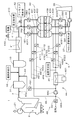
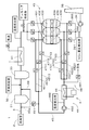
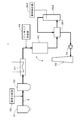
- FIG. 1 is a diagram showing a configuration of an incinerator 1 according to an embodiment of the present invention.
- the incinerator 1 is, for example, a stalker-type incinerator that burns waste as a waste while conveying it with a plurality of grate (stalkers).
- the incinerator 1 may be an incinerator other than a stoker type incinerator (for example, a fluidized bed furnace, a kiln furnace, etc.).
- the incinerator 1 includes a combustion chamber 2 and a discharge path 3.
- combustion of garbage and combustion of combustible gas generated from the garbage are performed.
- the discharge path 3 discharges exhaust gas (combustion gas) generated in the combustion chamber 2 from the combustion chamber 2 and guides it to the chimney 35. That is, the exhaust gas having the combustion chamber 2 as a generation source flows in the exhaust path 3 from the combustion chamber 2 toward the chimney 35.
- the chimney 35 emits exhaust gas to the atmosphere.
- the discharge path 3 is indicated by a thick solid line.
- the temperature reducing tower 31 supplies water to the exhaust gas to reduce the temperature of the exhaust gas.
- the chemical supply unit 32 blows a desalting and desulfurizing chemical (for example, powder of slaked lime) into the exhaust passage 3 on the inlet side of the bag filter 33 with respect to the exhaust gas flowing in the exhaust passage 3.
- a desalting / desulfurization reaction is caused in the inside and the bag filter 33, and dust contained in the reaction product and exhaust gas is removed.
- the chemical supply unit 32 and the bag filter 33 are a demineralizer and a desulfurizer.
- the bag filter 33 also removes soot and dust contained in the exhaust gas.
- the exhaust gas denitration device 4 sprays ammonia on the inlet side, decomposes nitrogen oxides (NOx) by catalytic reaction, and decomposes dioxins generated by waste incineration depending on the catalyst used.
- the induction ventilator 34 guides the exhaust gas in the discharge path 3 to the chimney 35.
- the exhaust gas denitration apparatus 4 includes an exhaust gas heater 41, an ammonia supply unit 42, a catalyst reaction tower 43, a catalyst regeneration unit 44, and a control unit 400 shown in FIG.
- the control unit 400 is responsible for overall control of the exhaust gas denitration apparatus 4.
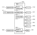
- the control unit 400 includes an exhaust gas temperature control unit 410, a denitration control unit 420, a switching control unit 470, and a circulating gas temperature control unit 460.
- a heat source 411 is connected to the exhaust gas heater 41 via a valve 412. Further, a temperature detector 413 that detects the temperature of the exhaust gas discharged from the exhaust gas heater 41 is provided in the vicinity of the downstream side of the exhaust gas heater 41 in the discharge path 3. The detection value of the temperature detection unit 413 is input to the exhaust gas temperature control unit 410, and the flow rate of the heat medium supplied from the heat source 411 to the exhaust gas heater 41 is changed by controlling the opening of the valve 412 based on the detection value. .
- the heat source 411 is, for example, a boiler 21 provided above the combustion chamber 2, and steam from the boiler 21 is supplied to the exhaust gas heater 41 as a heat medium.
- the exhaust gas heater 41 heats the exhaust gas discharged from the bag filter 33 to a predetermined temperature.
- the ammonia supply unit 42 is connected to the discharge passage 3 via a valve 421, and ammonia as a reducing agent is supplied to the exhaust gas discharged from the exhaust gas heater 41, and inflow passages 381 to 383 to the catalytic reaction tower 43 branching into a plurality of chambers. Supply to the upstream side.
- the ammonia supply unit 42 may be provided on the upstream side of the exhaust gas heater 41, and is preferably provided on the downstream side of the bag filter 33.
- a denitration control unit 420 is connected to the ammonia supply unit 42 in order to control the supply amount by controlling the opening degree of the valve 421 or controlling the stroke or rotation speed of the ammonia water supply pump.
- the denitration control unit 420 has a function of controlling the ammonia supply amount based on the input value from the NOx concentration detection unit 37 that detects the NOx concentration in the exhaust gas discharged from the chimney 35.
- a NOx concentration detection unit may also be provided at the outlet of the bag filter 33 to improve controllability.
- the catalytic reaction tower 43 which is a catalytic reactor has a plurality of catalyst chambers 431, 432 and 433.
- a plurality of catalyst modules 439 are accommodated in the plurality of catalyst chambers 431 to 433, respectively. In the example of FIG. 1, one catalyst module 439 is accommodated in each of the catalyst chambers 431 to 433. In the present embodiment, the same amount of catalyst is held in the plurality of catalyst chambers 431 to 433.
- the discharge path 3 is branched into a plurality of inflow paths 381 to 383, and the plurality of inflow paths 381 to 383 are connected to the inlets of the plurality of catalyst chambers 431 to 433, respectively.
- the Dampers 4011 to 4013 are provided in the inflow paths 381 to 383, respectively.
- a plurality of outflow passages 391 to 393 of the discharge passage 3 are connected to the outlets of the plurality of catalyst chambers 431 to 433, and the plurality of outflow passages 391 to 393 are joined together and connected to the induction fan 34. Dampers 4021 to 4023 are provided in the outflow paths 391 to 393, respectively.
- the exhaust gas heater 41, the ammonia supply unit 42, and the catalytic reaction tower 43 are provided in order from the upstream side to the downstream side in the discharge path 3.
- three catalyst chambers 431 to 433 are provided. In the following description, they are referred to as “first catalyst chamber 431”, “second catalyst chamber 432”, and “third catalyst chamber 433”. .
- the catalyst regeneration unit 44 includes a circulation channel 45, a circulation gas heater 46, and a circulation gas blower 450.
- the circulation gas heater 46 and the circulation gas blower 450 are provided in the circulation channel 45.
- the circulation channel 45 includes a plurality of first auxiliary channels 4511 to 4513 and a plurality of second auxiliary channels 4521 to 4523.
- the plurality of first auxiliary channels 4511 to 4513 are connected to the plurality of inflow channels 381 to 383, respectively.
- Dampers 4711 to 4713 are provided in the first auxiliary channels 4511 to 4513, respectively.
- the plurality of first auxiliary flow paths 4511 to 4513 are connected to each other on the side opposite to the inflow paths 381 to 383 to form one flow path, and are connected to the circulating gas blower 450.
- the plurality of second auxiliary channels 4521 to 4523 are connected to the plurality of outflow channels 391 to 393, respectively. Dampers 4721 to 4723 are provided in the second auxiliary channels 4521 to 4523, respectively.
- the plurality of second auxiliary flow paths 4521 to 4523 are connected to each other on the side opposite to the outflow paths 391 to 393, and are connected to the circulating gas heater 46 as one flow path.
- any one of the first to third catalyst chambers 431 to 433 is selectively included in the circulation channel 45.
- the damper 4711 of the first auxiliary flow path 4511 connected to the inflow path 381 of the first catalyst chamber 431, and the first catalyst chamber 431 The damper 4721 of the second auxiliary channel 4521 connected to the outflow passage 391 is opened, and the remaining dampers 4712, 4713, 4722, 4723 are closed. Further, the damper 4011 of the inflow passage 381 and the damper 4021 of the outflow passage 391 of the first catalyst chamber 431 are also closed.
- the circulation channel 45 returning to the first catalyst chamber 431 is formed via a part of The formation of the circulation channel 45 including the second catalyst chamber 432 and the formation of the circulation channel 45 including the third catalyst chamber 433 are the same as described above.
- dampers 4711 to 4713 (generically referred to as “damper 471” in FIG. 2) of the plurality of first auxiliary channels 4511 to 4513, and a plurality of second auxiliary channels 4521 to 4523.
- the dampers 4721 to 4723 (collectively referred to as “damper 472” in FIG. 2) provide a switching unit that includes the catalyst chamber selected from among the plurality of catalyst chambers 431 to 433 as part of the circulation channel 45.
- the switching unit is controlled by the switching control unit 470.
- the switching control unit 470 includes dampers 4011 to 4013 (generically referred to as “damper 401” in FIG. 2) of the plurality of inflow paths 381 to 383 and dampers 4021 to 4023 of the plurality of outflow paths 391 to 393 ( In FIG. 2, “damper 402” is collectively referred to).
- the circulating gas blower 450 is driven to drive the circulating gas heater 46, any of the second auxiliary flow paths 4521 to 4523, the catalyst chamber, and any of the first auxiliary flow paths 4511 to 4513 in this order (
- the gas in the circulation channel 45 (hereinafter referred to as “circulation gas”) circulates.
- the circulating gas may circulate in the clockwise direction in the circulation channel 45 of FIG.
- the circulation gas heater 46 heats the circulation gas flowing in the circulation flow path 45 with a heat medium or the like from the heat source 461.
- a temperature detector 462 for detecting the temperature of the circulation gas is provided in the vicinity of the downstream side of the circulation gas heater 46 (between the circulation gas heater 46 and the second auxiliary channels 4521 to 4523). It is done.
- the detection value of the temperature detector 462 is input to the circulating gas temperature controller 460, and the amount of heat of the circulating gas heater 46 is controlled.
- an air introduction unit 48 is connected to a position 453 (hereinafter referred to as “introduction position 453”) between the plurality of first auxiliary channels 4511 to 4513 and the circulation gas blower 450.
- the air introduction unit 48 includes a damper 481. By opening the damper 481, external air is introduced into the circulation channel 45 by the circulation gas blower 450.
- one end of a connection channel 49 is connected between the circulation gas blower 450 and the circulation gas heater 46.
- the other end of the connection channel 49 is connected to a position between the temperature reducing tower 31 and the drug supply unit 32 (by the drug supply position) in the discharge path 3.
- a damper 491 is provided in the connection channel 49. By opening the damper 491, a part of the circulating gas flowing in the circulation channel 45 flows into the discharge channel 3 through the connection channel 49.
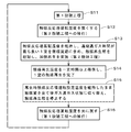
- FIG. 3 is a diagram showing a flow of processing related to denitration in the incinerator 1
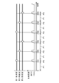
- FIG. 4 is a diagram showing a time chart of processing related to denitration.
- a period in which each catalyst chamber is used for denitration is indicated by a thick solid line, and a period in which each catalyst chamber is not used is indicated by a white rectangle.
- the lower part of FIG. 4 shows the heating temperature of the exhaust gas by the exhaust gas heater 41, that is, the operating temperature of the catalytic reaction tower 43.
- exhaust gas denitration is continuously performed by the exhaust gas denitration device 4 while garbage is burned in the combustion chamber 2.
- the exhaust gas discharged from the bag filter 33 is heated by the exhaust gas heater 41 to a constant normal-time catalytic reaction tower operation set temperature (170 ° C. in FIG. 4).
- the period during which the normal operation is performed in the exhaust gas denitration apparatus 4 is indicated by an arrow with a reference sign P ⁇ b> 1.
- the dampers 4011 to 4013 of all the inflow paths 381 to 383 and the dampers 4021 to 4023 of all the outflow paths 391 to 393 are opened.
- the exhaust gas flowing through the discharge passage 3 continuously flows into the first to third catalyst chambers 431 to 433 through the plurality of inflow passages 381 to 383 and is denitrated by the plurality of catalyst modules 439.
- a flow meter and a differential pressure meter (not shown) are provided, and dampers for a plurality of inflow passages 381 to 383 are provided so that the flow rates of the exhaust gas flowing into the first to third catalyst chambers 431 to 433 are equal.
- the opening degree of 4011 to 4013 is controlled.
- the denitrated exhaust gas is guided to the chimney 35 through a plurality of outflow passages 391 to 393 and discharged to the atmosphere.
- the catalyst modules in the first to third catalyst chambers 431 to 433 are maintained while the temperature of the exhaust gas flowing into the catalyst reaction tower 43 is kept at the normal catalyst reaction tower operation set temperature.
- the state in which the exhaust gas is denitrated using 439 (hereinafter referred to as “first denitration state”) is maintained (step S11).
- first denitration state all the dampers 4711 to 4713 of the first auxiliary flow paths 4511 to 4513 and all the dampers 4721 to 4723 of the second auxiliary flow paths 4521 to 4523 are closed.
- a high temperature operation for regenerating the catalyst module 439 in one catalyst chamber 431 to 433 is performed.
- the period during which the high-temperature operation is performed in the exhaust gas denitration apparatus 4 is indicated by an arrow with a reference symbol P2.
- the exhaust gas heating temperature by the exhaust gas heater 41 is gradually increased from the normal catalyst reaction tower operation set temperature by the control of the exhaust gas temperature control unit 410 (step S12).
- the exhaust gas heating temperature that is, the catalytic reaction tower operation temperature
- a predetermined regeneration catalyst reaction tower operation set temperature 200 ° C. in FIG. 4
- the catalyst chamber selected as the catalyst chamber in which the internal catalyst module 439 is to be regenerated (here, the catalyst chamber having the longest continuous gas passage time, A catalyst chamber ”) is identified, and an inflow path damper (a damper 4011 to 4013 of one inflow path 381 to 383) and an outflow path damper (a single outflow path 391 to 393) connected to the selected catalyst chamber.
- the dampers 4021 to 4023) are closed.
- the catalyst module 439 in the selected catalyst chamber is not used for exhaust gas denitration.
- exhaust gas at the regeneration catalyst reaction tower operation set temperature higher than the normal catalyst reaction tower operation set temperature continues. Inflow.
- the temperature of the exhaust gas flowing into the catalytic reaction tower 43 is made higher than that in the first denitration state using the exhaust gas heater 41, and the catalyst module 439 that is less in the first denitration state is used.
- a state in which the exhaust gas is denitrated by use (hereinafter referred to as “second denitration state”) is realized. The second denitration state is maintained for a predetermined period.
- the damper of the first auxiliary flow path (the dampers 4711 to 4713 of one first auxiliary flow path 4511 to 4513) connected to the selected catalyst chamber, and the second The damper of the auxiliary channel (the dampers 4721 to 4723 of one second auxiliary channel 4521 to 4523) is opened, and the circulation channel 45 including the selected catalyst chamber is formed. That is, the switching control unit 470 includes the selected catalyst chamber in a part of the circulation flow path 45. Subsequently, by starting to drive the circulation gas blower 450, the circulation of the gas existing in the circulation flow path 45, that is, the circulation gas is started. Circulation of the circulating gas is performed in parallel with the period of the second denitration state. As will be described later, the circulating gas is mainly air.
- the circulating gas flowing in the circulation channel 45 is heated by the circulating gas heater 46, and the circulating gas gradually increases in temperature. At this time, the temperature of the circulating gas is rapidly increased because the temperature of the selected catalyst chamber itself is in the vicinity of the regeneration reaction tower operation set temperature during regeneration.
- a predetermined catalyst regeneration temperature for example, about 300 ° C.
- thermal decomposition of unnecessary substances here, ammonium sulfate and acidic ammonium sulfate
- ammonium sulfate and acidic ammonium sulfate are decomposed into SO 3 (sulfur trioxide) and NH 3 (ammonia) and mixed with the circulating gas.
- SO 3 sulfur trioxide
- NH 3 ammonia
- a circulating gas having a predetermined temperature or higher is regarded as a catalyst regeneration gas.
- NH 3 contained in the circulating gas is used for a denitration reaction (a denitration reaction in the catalyst module 439 in the catalyst chamber other than the selected catalyst chamber) in the catalytic reaction tower 43 provided on the downstream side of the chemical supply unit 32.
- the openings of the dampers 481, 491 are set so that the flow rate of the circulation gas flowing out from the connection channel 49 becomes equal to the flow rate of air flowing into the circulation channel 45 by the air introduction part 48. Etc. are preferably adjusted. Since the flow rate of the circulating gas flowing out from the connection flow path 49 into the discharge path 3 is sufficiently lower than the flow rate of the exhaust gas flowing through the discharge path 3, the temperature of the exhaust gas changes excessively due to the mixing of the circulating gas. Absent.
- the circulating gas heater 46 when it is confirmed that the circulating gas has reached a second set temperature (eg, 370 ° C.) higher than the first set temperature, the circulating gas reaches the second set temperature for a predetermined time. And kept constant. As described above, while maintaining the second denitration state, unnecessary substances attached to the catalyst module 439 in the selected catalyst chamber are removed, that is, the heating regeneration of the catalyst module 439 is performed for a predetermined time (step S14). In the example of FIG. 4, it has been confirmed that the activity of the catalyst module 439 recovers to 95% or more.
- a second set temperature eg, 370 ° C.
- the driving of the circulating gas blower 450 is stopped, and the circulation of the circulating gas in the circulation channel 45 is stopped.
- SO 3 concentration meter and the connecting channel 49, NH 3 concentration meter is provided, the SO 3 concentration and the NH 3 concentration in the circulating gas towards the discharge passage 3 from the circulation flow path 45 is decreased to a predetermined value or less.
- the temperature of the circulating gas is 370 ° C. or higher, unnecessary substances adhering to the catalyst module 439 are sublimated in a short time, so no problem occurs even if the concentration meter is omitted.
- the temperature of the circulating gas and the time required for regeneration may be determined according to the type of catalyst used.
- Step S15 That is, all the catalyst chambers 431 to 433 are switched to the exhaust gas passing state.
- the heating temperature of the exhaust gas is gradually lowered from the regeneration catalytic reaction tower operation set temperature (step S16).
- the exhaust gas discharged from the exhaust gas heater 41 reaches the normal catalyst reaction tower operation set temperature, it is kept constant at the normal catalyst reaction tower operation set temperature. Thereby, the catalytic reaction tower 43 is returned to the first denitration state (step S11).
- the catalyst chambers 431 to 433 are selected as selected catalyst chambers in order at regular intervals, and the catalyst modules 439 in the catalyst chambers 431 to 433 are regenerated by executing steps S12 to S16. .
- the first to third catalyst chambers 431 to 433 are selected catalyst so that the period P2 during which the high temperature operation is performed is a constant interval (equal allocation), that is, the regeneration interval is constant. The time selected as a room is shifted.
- regeneration of the catalyst module 439 is performed once every 1500 hours, and in the entire catalyst reaction tower 43, regeneration of the catalyst module 439 is performed once every 500 hours.
- the regeneration interval of 1500 hours is merely an example, and the actual regeneration interval is determined for each plant based on design conditions and confirmation in trial operation.
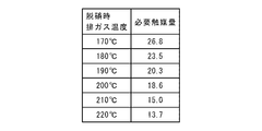
- FIG. 5 is a graph showing the relationship between the exhaust gas temperature during denitration and the required amount of catalyst.
- the required amount of catalyst at each NOx exhaust gas temperature the type of catalyst, the exhaust gas flow rate flowing into the catalytic reaction tower 43, the nitrogen oxide concentration (or dioxin concentration) in the exhaust gas, the nitrogen oxide removal rate (or Dioxin removal rate), ammonia leak amount, etc. are set to predetermined conditions.
- the required amount of catalyst is 26.8 m 3 .
- three catalyst chambers are provided in the catalyst reaction tower 43, in consideration of a period during which one catalyst chamber is not used for catalyst regeneration (hereinafter referred to as “partial use period”), two catalyst chambers are used.
- the amount of catalyst that needs to be filled in this catalyst chamber is 26.8 m 3 .
- the catalyst activity gradually decreases due to the deposition of unnecessary substances, it is necessary to allow a certain margin (the same applies hereinafter).
- the exhaust gas temperature at the time of denitration in normal operation is set to 170 ° C., and the exhaust gas temperature at the time of denitration is increased to 200 ° C. immediately before the partial use period, whereby the amount of catalyst that needs to be filled in the two catalyst chambers is 18.6 m 3. It becomes.
- filled catalyst amount The total amount of catalyst that needs to be filled in the chamber (hereinafter referred to as “filled catalyst amount”) is twice and 1.5 times the necessary amount of catalyst, respectively.
- the amount of the filled catalyst can be reduced.
- the amount of the packed catalyst is a minimum of 40.2 m 3 in the catalyst reaction tower 43 provided with three catalyst chambers.
- the amount of the filled catalyst is 27.9 m 3 , and only one catalyst chamber is provided while the exhaust gas temperature at the time of denitration is kept constant at 170 ° It is possible to make the amount of the filled catalyst almost the same.
- the number of catalyst chambers is n (n is an integer of 2 or more), and the required denitration performance is continuously obtained at the regeneration catalyst operation tower operation set temperature in (n ⁇ 1) catalyst chambers.
- the amount of packed catalyst is determined so as to satisfy the demand. Actually, in the determination of the charged catalyst amount, a decrease in the catalyst activity during the regeneration interval is also taken into consideration.
- the exhaust gas denitration device 4 of FIG. 1 a plurality of catalyst modules 439 are accommodated, and the catalyst reaction tower 43 into which the exhaust gas flows and the upstream side of the catalyst reaction tower 43 in the exhaust gas flow direction are arranged.
- An exhaust gas heater 41 is provided. Then, the first denitration state in which the exhaust gas is denitrated using a plurality of catalyst modules 439 in the catalyst reaction tower 43, and the temperature of the exhaust gas flowing into the catalyst reaction tower 43 are converted into the first denitration state using the exhaust gas heater 41.
- the control unit 400 switches between a second denitration state in which exhaust gas is denitrated using fewer catalyst modules 439 than in the first denitration state. In this way, by increasing the temperature of the exhaust gas flowing into the catalytic reaction tower 43, it is possible to suppress a reduction in the denitration performance when a part of the plurality of catalyst modules 439 is used for denitration.
- the temperature of the exhaust gas in the bag filter is set to about 150 ° C., so the heating temperature is used to suppress the catalyst deterioration rate due to precipitation of ammonium sulfate or acidic ammonium sulfate.
- the exhaust gas temperature during denitration during normal operation can be relatively low (170 ° C. in the example of FIG. 4), so the heating temperature in the exhaust gas heater 41 is lowered.
- the consumption of steam can be suppressed.
- the power generation efficiency in the incinerator 1 can be improved.
- the exhaust gas at 150 ° C. is heated to 170 ° C. by the exhaust gas heater 41 during normal operation, it is 1.5% compared to the case of heating to a certain temperature (200 ° C.) in order to suppress the precipitation of unnecessary substances.
- % Improvement in power generation efficiency is possible.
- the exhaust gas temperature during denitration is set to 200 ° C.
- the catalytic reaction tower 43 has a plurality of catalyst chambers 431 to 433 provided in parallel to the flow of exhaust gas, and the exhaust gas heater 41 leads to the plurality of catalyst chambers 431 to 433.
- a plurality of exhaust gas flow paths (that is, the inflow paths 381 to 383) can be individually opened and closed. Thereby, in the exhaust gas denitration apparatus 4, denitration can be continuously performed while the catalyst modules 439 in some catalyst chambers are not used. Thereby, the operation time (incineration amount) calculated
- the catalyst regeneration unit 44 can selectively supply a catalyst regeneration gas (in the above, heated circulating gas) to the plurality of catalyst chambers 431 to 433.
- a catalyst regeneration gas in the above, heated circulating gas
- the catalyst module 439 can be easily regenerated in the catalyst chambers 431 to 433 (that is, online).
- the switching control unit 470 includes the selected catalyst chamber in a part of the circulation channel 45, and the circulation gas circulating through the circulation channel 45 is heated by the circulation gas heater 46. Thereby, it is possible to easily prepare (generate) a catalyst regeneration gas that is a circulating gas at a predetermined temperature or higher.
- the heating temperature by the circulating gas heater 46 at the time of heating regeneration is, for example, It becomes about 120-170 ° C.
- the circulating gas at 320 ° C. is circulated for about 2 hours. By doing so, the activity is restored to almost 100%.
- the gas used for the heat regeneration of the catalyst module contains harmful SO 3 and NH 3 .
- mix a small amount of SO 3 and NH 3 in the exhaust gas discharged assuming an exhaust gas denitration apparatus of the comparative example is discharged to the atmosphere.
- the temperature of the gas used for the heat regeneration is set lower than the sublimation temperature of ammonium sulfate or acidic ammonium sulfate, and the catalyst is heated and regenerated while the decomposition rate of ammonium sulfate or acidic ammonium sulfate is slowed.
- a desulfurization device is provided in the exhaust passage 3 from the combustion chamber 2 to the exhaust gas heater 41, and the circulating gas that has passed through the selected catalyst chamber is in the exhaust passage 3. It flows into the upstream side of the desulfurization unit.
- SO 3 and the like contained in the circulating gas that has passed through the selected catalyst chamber can be removed, and the exhaust gas is appropriately brought into the atmosphere without performing complicated processing such as controlling the decomposition rate of ammonium sulfate or acidic ammonium sulfate. Can be released.
- the incinerator 1 since the desulfurization apparatus is normally provided, the increase in the manufacturing cost of the incinerator 1 and the exhaust gas denitration apparatus 4 is also suppressed.
- NH 3 contained in the circulating gas is used for the denitration reaction in the catalyst chamber (the catalyst chamber other than the selected catalyst chamber) during the denitration in the catalytic reaction tower 43.
- a chemical for demineralization and desulfurization is sprayed into the discharge path 3 by the chemical supply unit 32.
- the chemical supply unit 32 is omitted and the temperature reducing tower 31 is provided.
- the temperature reducing tower 31 is regarded as a desulfurization apparatus.
- the end of the connection flow path is connected in the vicinity of the upstream side of the temperature reducing tower 31, and SO 3 or the like contained in the circulating gas is reduced to the temperature reducing tower 31. Removed.
- the catalyst performance at each time is calculated from the nitrogen oxide concentration by the NOx concentration detector 37 provided on the upstream side of the chimney 35, and the timing for performing the heat regeneration of the catalyst module 439 is determined based on the catalyst performance. Also good.
- the timing for performing the heat regeneration can be freely determined.
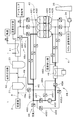
- FIG. 6 is a view showing another example of the exhaust gas denitration apparatus 4.
- an exhaust gas introduction unit 48 a is added to the exhaust gas denitration device 4 in FIG. 1, and the exhaust gas can be introduced into the circulation channel 45 of the catalyst regeneration unit 44.
- Other configurations are the same as those in FIG. 1, and the same components are denoted by the same reference numerals.
- the exhaust gas introduction part 48 a includes an exhaust gas introduction channel 482 and a damper 483.
- One end of the exhaust gas introduction channel 482 is connected to a position between the exhaust gas heater 41 and the ammonia supply unit 42 in the exhaust channel 3.
- the other end of the exhaust gas introduction passage 482 is connected to a position between the plurality of first auxiliary passages 4511 to 4513 and the circulation gas blower 450 in the circulation passage 45.
- the damper 483 is provided in the exhaust gas introduction flow path 482.
- the circulation channel 45 including the selected catalyst chamber is formed. Subsequently, by opening the damper 483 of the exhaust gas introduction flow path 482, the exhaust gas that passes through the bag filter 33 and is heated by the exhaust gas heater 41 is introduced into the circulation flow path 45.
- the temperature of the exhaust gas discharged from the exhaust gas heater 41 is set to a regeneration catalyst reaction tower operation set temperature (for example, 200 ° C.) higher than normal. Is done. In this way, the gas that has been at a high temperature in advance is introduced into the circulation channel 45.
- the exhaust gas is heated by the circulating gas heater 46 while being circulated through the circulating flow path 45 as a circulating gas by driving the circulating gas blower 450.
- the damper 483 of the exhaust gas introduction channel 482 is opened for a predetermined time and a necessary amount of exhaust gas is introduced into the circulation channel 45, the damper 483 is closed.
- the dampers 483 and 491 are opened.
- the introduction of the exhaust gas by the exhaust gas introducing portion 48a is resumed, a portion of the circulating gas containing the product in the thermal regeneration (SO 3, etc.), via a connecting channel 49, the drug supply in the discharge passage 3 It flows in the vicinity of the upstream side of the portion 32.
- SO 3 and the like in the circulating gas flowing into the discharge path 3 are removed by the discharge path 3 and the bag filter 33.
- the exhaust gas heated by the exhaust gas heater 41 is introduced into the circulation channel 45 of the catalyst regeneration unit 44, and the exhaust gas circulates in the circulation channel 45 as a circulation gas. While being heated by the circulating gas heater 46.
- the circulation gas is heated to a predetermined catalyst regeneration temperature in a short time while reducing heat consumption in the circulation gas heater 46. It becomes possible.
- external air can be heated and used for heating regeneration of the catalyst module 439.
- FIG. 7 is a view showing another example of the exhaust gas denitration apparatus 4.
- the circulating gas blower 450 is attached in the opposite direction to that in FIG. 1 so that the circulating gas circulates in the circulation channel 45 in the clockwise direction.
- the connection flow path 49 is connected to a position between the circulation gas blower 450 and the plurality of first auxiliary flow paths 4511 to 4513, and the air introduction part 48 is connected to the plurality of second auxiliary flow flows.
- the temperature detection unit 462 is provided between the circulating gas heater 46 and the circulating gas blower 450.
- the dampers 4721 to 4723 of the plurality of second auxiliary channels 4521 to 4523 and the dampers 4711 to 4713 of the plurality of first auxiliary channels 4511 to 4513 are slightly set.
- a circulation channel 45 including all the catalyst chambers 431 to 433 is formed.
- a part of the exhaust gas that has passed through the catalyst chambers 431 to 433 sequentially passes through the second auxiliary flow paths 4521 to 4523, the circulation gas heater 46, the circulation gas blower 450, and the first auxiliary flow paths 4511 to 4513, Return to the catalyst chambers 431-433.
- the circulation channel 45 including the selected catalyst chamber is formed.
- the circulation channel 45 including the first catalyst chamber 431 is formed.
- the exhaust gas from the exhaust gas heater 41 does not flow into the first catalyst chamber 431 but flows into only the second and third catalyst chambers 432 and 433.
- the dampers 4722 and 4723 of the second auxiliary flow paths 4522 and 4523 connected to the second and third catalyst chambers 432 and 433 are also opened. As a result, part of the exhaust gas that has passed through the second and third catalyst chambers 432 and 433 is introduced into the circulation channel 45 including the first catalyst chamber 431.
- the circulation channel 45 and the second auxiliary channels 4522 and 4523 are indicated by thick solid lines.
- the exhaust gas is heated by the circulation gas heater 46 while being circulated through the circulation channel 45 as a circulation gas by driving the circulation gas blower 450.
- the dampers 4722 and 4723 are closed.
- only one of the dampers 4722 and 4723 of the two second auxiliary channels 4522 and 4523 may be opened.
- the dampers 491, 4722, 4723 are opened.
- the introduction of the exhaust gas from the second auxiliary flow paths 4522 and 4523 is resumed, and a part of the circulating gas containing SO 3 and the like passes through the connection flow path 49 and the medicine supply section 32 in the discharge path 3 In the vicinity of the upstream side.
- the circulating gas heater 46 is turned off.
- the damper 491 is closed and the catalytic reaction tower 43 is returned to the first denitration state in which the exhaust gas denitration is performed using the catalyst modules 439 in all the catalyst chambers 431 to 433. Further, the dampers 4721 to 4723 of the plurality of second auxiliary channels 4521 to 4523 and the dampers 4711 to 4713 of the plurality of first auxiliary channels 4511 to 4513 are slightly opened, and all the catalyst chambers 431 are set. A circulation channel 45 including ⁇ 433 is formed.
- FIG. 8 is a view showing another example of the exhaust gas denitration apparatus 4. 8 differs from the exhaust gas denitration device 4 of FIG. 6 in that two additional flow paths 455 and 456 are added. Specifically, in the circulation channel 45, a damper 457 is provided between the introduction position 453 of the air introduction part 48 and the circulation gas blower 450, and a damper is provided between the circulation gas blower 450 and the circulation gas heater 46. 458 is provided. One end of the first additional flow path 455 is connected between the introduction position 453 of the air introduction part 48 and the damper 457, and the other end of the first additional flow path 455 is between the circulating gas blower 450 and the damper 458. Connected.
- Two dampers 4551 and 4552 are provided in the first additional flow path 455.
- One end of the second additional flow path 456 is connected between the damper 457 and the circulating gas blower 450, and the other end of the second additional flow path 456 is connected between the damper 458 and the circulating gas heater 46.
- One damper 4561 is provided in the second additional channel 456.
- the dampers 457 and 458 provided on both sides of the circulating gas blower 450 in the circulation channel 45 are opened, and the first and second additional channels 455 and 456 are opened.
- the dampers 4551, 4552, and 4561 are closed.
- the circulation flow path 45 including the selective catalyst chamber is formed.
- the exhaust gas heated by the exhaust gas heater 41 is introduced into the circulation passage 45 through the exhaust gas introduction passage 482.
- the circulation flow path 45 including the first catalyst chamber 431 and the exhaust gas introduction flow path 482 are indicated by thick solid lines.
- the operation related to the heating regeneration of the catalyst module 439 is the same as in the case of FIG.
- the circulation passage 45 including the catalyst chamber to be heated and regenerated next is warmed up.
- the damper 4722 of the second auxiliary channel 4522 and the damper 4712 of the first auxiliary channel 4512 shown in FIG. 9 are slightly opened. It is.
- the dampers 457 and 458 provided on both sides of the circulating gas blower 450 in the circulation channel 45 are closed, and the dampers 4551, 4552, and 4561 of the first and second additional channels 455 and 456 are opened.
- a part of the exhaust gas that has passed through the second catalyst chamber 432 becomes a second auxiliary flow path 4522, the circulation gas heater 46, the second additional flow path 456, the circulation gas blower 450, the first additional flow path 455, the first It returns to the 2nd catalyst chamber 432 through the 1 auxiliary flow path 4512 in order (refer the thick continuous line in FIG. 9).
- the circulating gas heater 46 is OFF, and the heating of the gas in the circulation channel 45 is not performed.
- the circulation flow path 45 including the second catalyst chamber 432 is warmed in the first denitration state.
- the catalyst module 439 in the second catalyst chamber 432 is heated and regenerated, the temperature increase rate of the circulating gas can be increased, and the time required for the heat regeneration can be shortened.
- the first and third catalyst chambers 431 and 433 are catalyst chambers to be heated and regenerated next time.
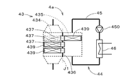
- FIG. 10 is a view showing another example of the exhaust gas denitration device, and shows a part of the exhaust gas denitration device 4a.
- FIG. 11 is a cross-sectional view of the catalytic reaction tower 43 of the exhaust gas denitration apparatus 4a, and shows a cross section perpendicular to the gas flow direction in the catalytic reaction tower 43.
- the catalytic reaction tower 43 has one catalyst chamber 434 and one catalyst regeneration chamber 435.
- the catalytic reaction tower 43 has a substantially cylindrical shape centered on a predetermined central axis J1, and a plate-like partition wall 436 parallel to the central axis J1 is provided in the internal space of the catalytic reaction tower 43.
- one space partitioned by the partition wall 436 is the catalyst chamber 434, and the other space is the catalyst regeneration chamber 435. That is, the catalyst chamber 434 and the catalyst regeneration chamber 435 are provided adjacent to each other.
- the partition wall portion 436 has a plurality of rotating portions 437 arranged along the central axis J1, and a semicircular and plate-like catalyst module 439 is attached to each rotating portion 437.
- the rotating unit 437 rotates the catalyst module 439 around the central axis J1 and selectively places the catalyst module 439 in the catalyst chamber 434 and the catalyst regeneration chamber 435.
- the catalyst regeneration chamber 435 is included in a part of the circulation channel 45.
- the circulation channel 45 includes a circulation gas blower 450 and a circulation gas heater 46.
- a plurality (all) of the catalyst modules 439 are arranged in the catalyst chamber 434. Exhaust gas flows into the catalyst chamber 434, and exhaust gas denitration is performed using the plurality of catalyst modules 439.
- the catalyst module 439 is arranged in the catalyst regeneration chamber 435 by the rotating unit 437.
- the catalyst regeneration chamber 435 is supplied with a circulation gas (catalyst regeneration gas) heated by the circulation gas heater 46 to regenerate the catalyst module 439.
- the circulating gas used for the regeneration of the catalyst module 439 flows into the discharge path 3 through the connection flow path (not shown) as in the exhaust gas denitration apparatus 4 of FIG.
- exhaust gas denitration is performed using the remaining catalyst module 439 except for the catalyst module 439.
- the heating temperature of the exhaust gas by the exhaust gas heater 41 is set higher than when all the catalyst modules 439 are used.
- the first denitration state in which the exhaust gas is denitrated using the plurality of catalyst modules 439 in the catalytic reaction tower 43, and the temperature of the exhaust gas flowing into the catalytic reaction tower 43 Is switched to the second denitration state in which the exhaust gas denitration is performed using the catalyst module 439 that is less than the first denitration state, while the exhaust gas heater 41 is used to make the temperature higher than the first denitration state.
- the exhaust gas heater 41 is used to make the temperature higher than the first denitration state.
- the plurality of rotating units 437 operate as position switching units that selectively (and individually) arrange the plurality of catalyst modules 439 in the catalyst chamber 434 and the catalyst regeneration chamber 435, respectively. To do.
- the position switching unit is controlled by a position switching control unit (not shown) of the control unit 400.
- each catalyst chamber is also provided when a plurality of catalyst chambers 431 and 432 are provided.
- a plurality of catalyst modules 439 may be provided in 431 and 432.
- the catalyst module 439 is a substantially continuous collection of catalysts.
- each catalyst module 439 is constituted by a plurality of catalyst cells adjacent to each other, with the smallest catalyst mass that can be handled as catalyst cells (or catalyst elements). May be.
- the catalyst regeneration chamber 435 may be omitted, the catalyst module 439 disposed outside the catalyst chamber 434 may be removed by the rotating portion 437, and may be regenerated in an external catalyst regeneration device. Further, in the exhaust gas denitration device 4 of FIG. 1, the catalyst chambers 431 to 433 can be opened and closed, and the catalyst module 439 in the selected catalyst chambers 431 to 433 is removed and regenerated in an external catalyst regeneration device. Also good. Further, the removed catalyst module 439 may be replaced with a new catalyst module 439. In the exhaust gas denitration apparatuses 4 and 4a, it is possible to suppress a decrease in the denitration performance by increasing the temperature of the exhaust gas flowing into the catalyst reaction tower 43 during regeneration or replacement of some of the catalyst modules 439.
- the number of catalyst chambers is 1 to 3, but the number of catalyst chambers may be 4 or more.
- the number of catalyst chambers is 3 or more, depending on the design of the apparatus, a plurality of catalyst chambers smaller than the total number of catalyst chambers may be simultaneously selected as the selected catalyst chamber.
- the number of selected catalyst chambers is one.
- the exhaust gas heater 41 may heat the exhaust gas using a gas other than the steam of the boiler 21.
- the circulating gas heater 46 may also heat the circulating gas using other energy such as gas.
- the exhaust gas heater 41 may heat the exhaust gas only when a part of the plurality of catalyst modules 439 is used for denitration.
- the catalyst regeneration gas is a deposit (precipitate) that reduces the denitration performance in the catalyst module 439.
- a specific type of gas may be used.
- a removal device for removing SO 3 and NH 3 in the circulation gas may be provided in the circulation channel 45. Further, when the desulfurization device is provided downstream of the catalyst reaction tower 43 in the discharge path 3, all or part of the catalyst regeneration gas discharged from the selected catalyst chamber in the catalyst regeneration unit 44 is You may flow into the discharge path 3 as it is.
- a gas gas heat exchanger 361 and a wet smoke-flushing tower 362 are provided in the discharge path 3 on the downstream side of the catalytic reaction tower 43.
- the wet smoke cleaning tower 362 is provided with a chemical supply unit 363.
- the exhaust gas discharged from the catalytic reaction tower 43 passes through the gas gas heat exchanger 361 and flows into the wet smoke cleaning tower 362. Inside the wet smoke cleaning tower 362, a chemical (caustic soda or the like) is sprayed by the chemical supply unit 363, and desalting and desulfurization are performed. That is, a desulfurization apparatus is realized by the wet smoke scouring tower 362.
- the exhaust gas that has passed through the wet smoke cleaning tower 362 is heated again by the gas gas heat exchanger 361 and discharged to the atmosphere via the chimney 35.
- a medicine such as slaked lime is sprayed.
- the catalyst reaction tower 43 of FIG. 13 when heating and regenerating one catalyst chamber, for example, the catalyst module 439 of the first catalyst chamber 431 in FIG. 1, the catalyst module 439 is opened by slightly opening the damper 4021.
- the gas used for the heating regeneration is guided to the wet smoke cleaning tower 362 in FIG. This makes it possible to remove SO 3 and the like contained in the gas that has passed through the selective catalyst chamber (here, the first catalyst chamber 431) in the wet smoke cleaning tower 362.
- the connection flow path 49 in FIG. 1 can be omitted.
- the exhaust gas denitration devices 4 and 4a may be used in equipment other than the incinerator 1 or devices such as a diesel engine.
Landscapes
- Engineering & Computer Science (AREA)
- Chemical & Material Sciences (AREA)
- Environmental & Geological Engineering (AREA)
- Health & Medical Sciences (AREA)
- Biomedical Technology (AREA)
- Analytical Chemistry (AREA)
- General Chemical & Material Sciences (AREA)
- Oil, Petroleum & Natural Gas (AREA)
- Chemical Kinetics & Catalysis (AREA)
- General Engineering & Computer Science (AREA)
- Mechanical Engineering (AREA)
- Exhaust Gas Treatment By Means Of Catalyst (AREA)
- Chimneys And Flues (AREA)
Abstract
排ガス脱硝装置(4)は、複数の触媒モジュール(439)を収容するとともに、排ガスが流入する触媒反応塔(43)と、排ガスの流れ方向において触媒反応塔(43)の上流側に配置される排ガス加熱器(41)とを備える。排ガス脱硝装置(4)では、触媒反応塔(43)において複数の触媒モジュール(439)を使用して排ガスの脱硝を行う第1脱硝状態と、触媒反応塔(43)に流入する排ガスの温度を、排ガス加熱器(41)を用いて第1脱硝状態よりも高くしつつ、第1脱硝状態よりも少ない触媒モジュール(439)を使用して排ガスの脱硝を行う第2脱硝状態とが切り替えられる。このように、触媒反応塔(43)に流入する排ガスの温度を高くすることにより、複数の触媒モジュール(439)の一部を脱硝に使用する場合における脱硝性能の低下を抑制することが実現される。
Description
本発明は、排ガス脱硝装置、焼却炉および排ガス脱硝方法に関する。
触媒を用いる排ガス脱硝装置では、触媒反応塔の運転温度や、排ガス中の水分、三酸化硫黄およびアンモニアの濃度を因子として、触媒表面に反応生成物である硫安や酸性硫安が析出することが知られている。反応生成物の析出により、触媒の活性度が低下し、要求される脱硝性能を満足することができなくなる。そこで、定期的に触媒を外部に運んで、水洗処理または加熱処理を行うことにより、触媒が再生される。しかしながら、上記作業を行う場合、排ガス脱硝装置および当該装置が設けられる設備の運転を停止する必要がある。そこで、特開平10-192657号公報(文献1)では、設備を停止することなく触媒の再生を行う手法が開示されている。当該手法では、触媒塔(触媒反応塔)の内部を2室以上に分割し、1室ずつ触媒の再生を行いながら、残りの室に排ガスを通して排ガスの脱硝が行われる。
なお、特開平10-15345号公報の燃焼排ガス浄化方法では、燃焼排ガスを、移動層式の脱硫層に導入して脱硫し、脱硫処理後の燃焼排ガスを二つに分割し、分割された排ガスのそれぞれの脱硫状態に応じて昇温調節され、脱硝層においてアンモニア接触還元脱硝が行われる。
ところで、文献1の手法では、触媒塔(触媒反応塔)に複数の触媒モジュールが設けられていると捉えた場合、1室ずつ行われる触媒の再生中に、脱硝に用いる触媒モジュールの個数が少なくなるため、脱硝性能が低下してしまう。
本発明は、排ガス脱硝装置に向けられており、複数の触媒モジュールの一部を脱硝に使用する場合における脱硝性能の低下を抑制することを目的としている。
本発明に係る排ガス脱硝装置は、複数の触媒モジュールを収容するとともに、排ガスが流入する触媒反応器と、前記排ガスの流れ方向において前記触媒反応器の上流側に配置される排ガス加熱器と、制御ユニットとを備え、前記制御ユニットが、前記触媒反応器において前記複数の触媒モジュールを使用して前記排ガスの脱硝を行う第1脱硝状態と、前記触媒反応器に流入する前記排ガスの温度を、前記排ガス加熱器を用いて前記第1脱硝状態よりも高くしつつ、前記第1脱硝状態よりも少ない触媒モジュールを使用して前記排ガスの脱硝を行う第2脱硝状態とを切り替える。
本発明によれば、複数の触媒モジュールの一部を脱硝に使用する場合における脱硝性能の低下を抑制することができる。
本発明の一の好ましい形態では、前記触媒反応器が、前記排ガスの流れに対して並列に設けられる複数の触媒室を有し、前記複数の触媒モジュールが前記複数の触媒室に収容され、前記排ガス加熱器から前記複数の触媒室へと至る前記排ガスの複数の流路が、個別に開閉可能である。
この場合に、好ましくは、排ガス脱硝装置が、触媒再生用ガスを前記複数の触媒室に対して選択的に供給可能である触媒再生部をさらに備える。
より好ましくは、前記触媒再生部が、循環ガスを循環させる循環流路と、前記循環流路に設けられ、前記循環ガスを加熱する循環ガス加熱器とを備え、前記制御ユニットが、前記複数の触媒室のうち選択された触媒室を前記循環流路の一部に含め、前記触媒再生用ガスが、循環することによって所定温度以上にまで昇温された前記循環ガスである。
例えば、前記排ガスの発生源から前記排ガスを排出する排出路において、脱硫装置が設けられており、選択された触媒室を通過した前記触媒再生用ガスが、前記排出路において前記脱硫装置の上流側に流入する。
本発明の他の好ましい形態では、前記触媒反応器が、前記排ガスが流入する触媒室と、前記触媒室に隣接して設けられ、触媒再生用ガスが供給される触媒再生室とを備え、前記制御ユニットが、前記複数の触媒モジュールのそれぞれを前記触媒室と前記触媒再生室とに選択的に配置する。
本発明は、焼却炉にも向けられている。本発明に係る焼却炉は、廃棄物を燃焼させる燃焼室と、前記燃焼室にて発生する排ガスを前記燃焼室から排出する排出路と、前記排出路に設けられる上記の排ガス脱硝装置とを備える。
本発明は、排ガス脱硝装置における排ガス脱硝方法にも向けられている。
上述の目的および他の目的、特徴、態様および利点は、添付した図面を参照して以下に行うこの発明の詳細な説明により明らかにされる。
図1は、本発明の一の実施の形態に係る焼却炉1の構成を示す図である。焼却炉1は、例えば、複数の火格子(ストーカ)により廃棄物であるごみを搬送しつつ燃焼させるストーカ式の焼却炉である。焼却炉1は、ストーカ式の焼却炉以外の焼却炉(例えば、流動床炉、キルン炉等)であってもよい。
焼却炉1は、燃焼室2と、排出路3とを備える。燃焼室2では、ごみの燃焼と、ごみから発生した可燃性ガスの燃焼とが行われる。排出路3は、燃焼室2にて発生する排ガス(燃焼ガス)を燃焼室2から排出し、煙突35へと導く。すなわち、燃焼室2を発生源とする排ガスは、燃焼室2から煙突35に向かって排出路3内を流れる。煙突35は、排ガスを大気に放出する。図1では、排出路3を太い実線にて示している。
排出路3には、燃焼室2から煙突35に向かって、すなわち、排ガスの流れ方向における上流側から下流側に向かって、減温塔31、薬剤供給部32、バグフィルタ33、排ガス脱硝装置4、誘引通風機34が順に設けられる。減温塔31は、排ガスに水を供給して排ガスの温度を低下させる。薬剤供給部32は、排出路3内を流れる排ガスに対して、脱塩および脱硫用の薬剤(例えば、消石灰の粉末)をバグフィルタ33入口側の排出路3において吹き込むことによって、排出路3の内部およびバグフィルタ33で脱塩・脱硫反応を起こし、その反応生成物や排ガス中に含有される粉塵を除去する。すなわち、薬剤供給部32およびバグフィルタ33は、脱塩装置であり、脱硫装置でもある。バグフィルタ33は、排ガスに含まれるばいじんも除去する。排ガス脱硝装置4は、入口側でアンモニアを噴霧し、触媒反応により窒素酸化物(NOx)を分解するとともに、使用される触媒によっては廃棄物焼却によって発生するダイオキシンを分解する。誘引通風機34は、排出路3内の排ガスを煙突35へと導く。
排ガス脱硝装置4は、排ガス加熱器41と、アンモニア供給部42と、触媒反応塔43と、触媒再生部44と、図2の制御ユニット400を備える。制御ユニット400は、排ガス脱硝装置4の全体制御を担う。制御ユニット400は、排ガス温度制御部410と、脱硝制御部420と、切替制御部470と、循環ガス温度制御部460とを備える。
図1の排ガス加熱器41は排出路3に設けられる。排ガス加熱器41には、バルブ412を介して熱源411が接続される。また、排出路3において排ガス加熱器41の下流側近傍には、排ガス加熱器41から排出される排ガスの温度を検出する温度検出部413が設けられる。温度検出部413の検出値は排ガス温度制御部410に入力され、当該検出値に基づくバルブ412の開度の制御により、熱源411から排ガス加熱器41に供給される熱媒体の流量が変更される。熱源411は、例えば燃焼室2の上方に設けられたボイラ21であり、ボイラ21からの蒸気が熱媒体として排ガス加熱器41に供給される。排ガス加熱器41により、バグフィルタ33から排出された排ガスが所定の温度に加熱される。
アンモニア供給部42はバルブ421を介して排出路3に接続され、排ガス加熱器41から排出された排ガスに還元剤であるアンモニアを、複数室に分岐する触媒反応塔43への流入路381~383よりも上流側に供給する。アンモニア供給部42は、排ガス加熱器41の上流側に設けられてもよく、好ましくは、バグフィルタ33よりも下流側に設けられる。アンモニア供給部42には、バルブ421の開度制御あるいはアンモニア水供給ポンプのストロークや回転数等の制御により供給量を制御するために、脱硝制御部420が接続される。脱硝制御部420は、煙突35から排出される排ガス中のNOx濃度を検出するNOx濃度検出部37からの入力値に基づきアンモニア供給量を制御する機能を有している。バグフィルタ33出口にもNOx濃度検出部を設けて、制御性を向上させることもある。触媒反応器である触媒反応塔43は、複数の触媒室431,432,433を有する。複数の触媒室431~433には、複数の触媒モジュール439がそれぞれ収容される。図1の例では、各触媒室431~433に1つの触媒モジュール439が収容される。本実施の形態では、複数の触媒室431~433において、同量の触媒が保持される。
触媒反応塔43の上流側近傍において、排出路3は複数の流入路381~383に分岐しており、複数の流入路381~383は、複数の触媒室431~433の流入口にそれぞれ接続される。各流入路381~383にはダンパ4011~4013が設けられる。複数の触媒室431~433の流出口には、排出路3の複数の流出路391~393が接続され、複数の流出路391~393は合流して誘引通風機34に接続される。各流出路391~393にはダンパ4021~4023が設けられる。排ガス脱硝装置4では、排ガス加熱器41、アンモニア供給部42および触媒反応塔43が、排出路3において上流側から下流側に向かって順に設けられる。図1の例では、3個の触媒室431~433が設けられており、以下の説明では、「第1触媒室431」、「第2触媒室432」および「第3触媒室433」と呼ぶ。
触媒再生部44は、循環流路45と、循環ガス加熱器46と、循環ガス送風機450とを有する。循環ガス加熱器46および循環ガス送風機450は、循環流路45に設けられる。循環流路45は、複数の第1補助流路4511~4513と、複数の第2補助流路4521~4523とを有する。複数の第1補助流路4511~4513は、複数の流入路381~383にそれぞれ接続される。各第1補助流路4511~4513にはダンパ4711~4713が設けられる。複数の第1補助流路4511~4513は、流入路381~383とは反対側において互いに結合して1つの流路となり、循環ガス送風機450に接続される。複数の第2補助流路4521~4523は、複数の流出路391~393にそれぞれ接続される。各第2補助流路4521~4523にはダンパ4721~4723が設けられる。複数の第2補助流路4521~4523は、流出路391~393とは反対側において互いに結合しており、1つの流路として循環ガス加熱器46に接続される。
触媒再生部44では、第1ないし第3触媒室431~433のうちのいずれかの触媒室が、選択的に循環流路45に含められる。例えば、第1触媒室431を含む循環流路45を形成する場合には、第1触媒室431の流入路381に接続された第1補助流路4511のダンパ4711、および、第1触媒室431の流出路391に接続された第2補助流路4521のダンパ4721が開かれ、残りのダンパ4712,4713,4722,4723が閉じられる。また、第1触媒室431の流入路381のダンパ4011、および、流出路391のダンパ4021も閉じられる。これにより、第1触媒室431から、流入路381(の一部)、第1補助流路4511、循環ガス送風機450、循環ガス加熱器46、第2補助流路4521、および、流出路391(の一部)を経由して、第1触媒室431へと戻る循環流路45が形成される。第2触媒室432を含む循環流路45の形成、および、第3触媒室433を含む循環流路45の形成も上記と同様である。排ガス脱硝装置4では、複数の第1補助流路4511~4513のダンパ4711~4713(図2では、「ダンパ471」と総称している。)、および、複数の第2補助流路4521~4523のダンパ4721~4723(図2では、「ダンパ472」と総称している。)により、複数の触媒室431~433のうち選択された触媒室を循環流路45の一部に含める切替部が実現され、当該切替部が切替制御部470により制御される。切替制御部470は、複数の流入路381~383のダンパ4011~4013(図2では、「ダンパ401」と総称している。)、および、複数の流出路391~393のダンパ4021~4023(図2では、「ダンパ402」と総称している。)の制御も行う。
図1の例では、循環ガス送風機450の駆動により、循環ガス加熱器46、いずれかの第2補助流路4521~4523、触媒室、いずれかの第1補助流路4511~4513の順にて(図1における反時計回りにて)、循環流路45内のガス(以下、「循環ガス」という。)が循環する。循環ガスは、図1の循環流路45を時計回りにて循環してもよい。循環ガス加熱器46は、熱源461からの熱媒体等により循環流路45内を流れる循環ガスを加熱する。循環流路45において、循環ガス加熱器46の下流側近傍(循環ガス加熱器46と第2補助流路4521~4523との間)には、循環ガスの温度を検出する温度検出部462が設けられる。温度検出部462の検出値は循環ガス温度制御部460に入力され、循環ガス加熱器46の熱量が制御される。
循環流路45において、複数の第1補助流路4511~4513と循環ガス送風機450との間の位置453(以下、「導入位置453」という。)には、空気導入部48が接続される。空気導入部48は、ダンパ481を有する。ダンパ481の開操作により、循環ガス送風機450によって外部の空気が循環流路45内に導入される。循環流路45において、循環ガス送風機450と循環ガス加熱器46との間には、接続流路49の一端が接続される。接続流路49の他端は、排出路3における減温塔31と薬剤供給部32(による薬剤の供給位置)との間の位置に接続される。接続流路49には、ダンパ491が設けられる。ダンパ491を開くことにより、循環流路45内を流れる循環ガスの一部が接続流路49を介して排出路3内に流入する。
図3は、焼却炉1における脱硝に係る処理の流れを示す図であり、図4は、脱硝に係る処理のタイムチャートを示す図である。図4の上段では、各触媒室を脱硝に使用している期間を太い実線にて示し、使用していない期間を白い矩形にて示している。図4の下段では、排ガス加熱器41による排ガスの加熱温度、すなわち触媒反応塔43の運転温度を示している。図1の焼却炉1では、燃焼室2においてごみを燃焼させている間、排ガス脱硝装置4による排ガスの脱硝が連続して行われる。排ガス脱硝装置4における通常運転では、バグフィルタ33から排出された排ガスが、排ガス加熱器41により一定の通常時触媒反応塔運転設定温度(図4では、170℃)に加熱される。図4では、排ガス脱硝装置4において通常運転が行われる期間を符号P1を付す矢印にて示している。
また、通常運転では、全ての流入路381~383のダンパ4011~4013、および、全ての流出路391~393のダンパ4021~4023が開かれる。これにより、排出路3を流れる排ガスが、複数の流入路381~383を介して第1ないし第3触媒室431~433に連続して流入し、複数の触媒モジュール439により脱硝される。好ましい排ガス脱硝装置4では、図示省略の流量計や差圧計が設けられ、第1ないし第3触媒室431~433に流入する排ガスの流量が等しくなるように、複数の流入路381~383のダンパ4011~4013の開度等が制御される。脱硝された排ガスは、複数の流出路391~393を介して煙突35へと導かれ、大気に排出される。このように、排ガス脱硝装置4における通常運転では、触媒反応塔43に流入する排ガスの温度を通常時触媒反応塔運転設定温度に保ちつつ、第1ないし第3触媒室431~433内の触媒モジュール439を使用して排ガスの脱硝を行う状態(以下、「第1脱硝状態」という。)が維持される(ステップS11)。なお、第1脱硝状態では、全ての第1補助流路4511~4513のダンパ4711~4713、および、全ての第2補助流路4521~4523のダンパ4721~4723は閉じられている。
通常運転が所定時間だけ継続されると、1つの触媒室431~433内の触媒モジュール439を再生させるための高温度運転が行われる。図4では、排ガス脱硝装置4において高温度運転が行われる期間を符号P2を付す矢印にて示している。高温度運転では、まず、排ガス温度制御部410の制御により排ガス加熱器41による排ガスの加熱温度が、通常時触媒反応塔運転設定温度から徐々に高くされる(ステップS12)。排ガスの加熱温度(すなわち、触媒反応塔運転温度)が、所定の再生時触媒反応塔運転設定温度(図4では、200℃)に到達すると、再生時触媒反応塔運転設定温度にて一定に保たれる。
続いて、複数の触媒室431~433のうち、内部の触媒モジュール439を再生させるべき触媒室として選択された触媒室(ここでは、連続通ガス時間が最も長い触媒室であり、以下、「選択触媒室」という。)が特定され、選択触媒室に接続する流入路のダンパ(1つの流入路381~383のダンパ4011~4013)、および、流出路のダンパ(1つの流出路391~393のダンパ4021~4023)が閉じられる。これにより、排ガス脱硝装置4では、選択触媒室内の触媒モジュール439が、排ガスの脱硝に使用されなくなる。一方、排ガスの脱硝に使用される触媒室、すなわち、選択触媒室を除く全ての触媒室には、通常時触媒反応塔運転設定温度よりも高い再生時触媒反応塔運転設定温度の排ガスが連続して流入する。このように、排ガス脱硝装置4では、触媒反応塔43に流入する排ガスの温度を、排ガス加熱器41を用いて第1脱硝状態よりも高くしつつ、第1脱硝状態よりも少ない触媒モジュール439を使用して排ガスの脱硝を行う状態(以下、「第2脱硝状態」という。)が実現される。第2脱硝状態は、所定の期間、維持される。
触媒再生部44では、切替制御部470の制御により、選択触媒室に接続された第1補助流路のダンパ(1つの第1補助流路4511~4513のダンパ4711~4713)、および、第2補助流路のダンパ(1つの第2補助流路4521~4523のダンパ4721~4723)が開かれ、選択触媒室を含む循環流路45が形成される。すなわち、切替制御部470により、選択触媒室が循環流路45の一部に含められる。続いて、循環ガス送風機450の駆動を開始することにより、循環流路45内に存在するガス、すなわち、循環ガスの循環が開始される。循環ガスの循環は、第2脱硝状態の期間に並行して行われる。後述するように、循環ガスは、主に空気である。
循環流路45内を流れる循環ガスは、循環ガス加熱器46により加熱され、循環ガスが徐々に昇温する。このとき、選択触媒室自体の温度が再生時触媒反応塔運転設定温度近傍となっていることにより、循環ガスの温度上昇が速やかとなる。循環ガスが所定の触媒再生温度(例えば300℃程度)まで昇温すると、選択触媒室内の触媒モジュール439に付着した不要物(ここでは、硫安および酸性硫安)の熱分解が始まる(ステップS13)。例えば、硫安および酸性硫安はSO3(三酸化硫黄)とNH3(アンモニア)に分解して、循環ガスに混ざる。触媒再生部44では、所定温度以上の循環ガスが、触媒再生用のガスとして捉えられる。
温度検出部462により、循環ガスが第1設定温度(例えば、300℃)まで昇温したことが確認されると、空気導入部48により外部の空気が導入位置453から循環流路45内に導入される。空気導入部48による空気の導入流量は、予め設定された循環ガスの昇温速度に合わせて決定される。また、接続流路49のダンパ491を開くことにより、循環ガスの一部が、排出路3における薬剤供給部32の上流側近傍に接続流路49を介して流入する。これにより、循環ガスに含まれるSO3が、排ガス中の硫黄酸化物(SOx)と共に排出路3およびバグフィルタ33において除去される。また、循環ガスに含まれるNH3は、薬剤供給部32よりも下流側に設けられる触媒反応塔43における脱硝反応(選択触媒室以外の触媒室内の触媒モジュール439における脱硝反応)に利用される。なお、循環流路45では、接続流路49から流出する循環ガスの流量が、空気導入部48により循環流路45内に流入する空気の流量と等しくなるように、ダンパ481,491の開度等が調整されることが好ましい。接続流路49から排出路3内に流出する循環ガスの流量は、排出路3を流れる排ガスの流量に比べて十分に低いため、循環ガスの混合により、排ガスの温度が過度に変化することはない。
循環ガス加熱器46では、循環ガスが、第1設定温度よりも高い第2設定温度(例えば370℃)に到達したことが確認されると、所定時間の間、循環ガスが第2設定温度にて一定に保たれる。以上のようにして、第2脱硝状態を維持しつつ、選択触媒室内の触媒モジュール439に付着した不要物の除去、すなわち、触媒モジュール439の加熱再生が一定時間行われる(ステップS14)。図4の例では、触媒モジュール439の活性度が95%以上まで回復することが確認されている。
その後、循環ガス送風機450の駆動が停止され、循環流路45における循環ガスの循環が停止される。なお、接続流路49にSO3濃度計や、NH3濃度計が設けられ、循環流路45から排出路3へと向かう循環ガスのSO3濃度やNH3濃度が所定値以下まで低下したことを確認した後に、循環ガスの循環が停止されることが望ましい。循環ガスの温度が370℃以上である場合には、触媒モジュール439に付着する不要物は短時間で昇華するため、上記濃度計を省略しても問題は生じない。もちろん、使用する触媒の種類等に応じて、循環ガスの温度や再生に要する時間が決定されてよい。
循環流路45における循環ガスの循環が停止されると、選択触媒室に接続された第1補助流路4511~4513のダンパ4711~4713、および、第2補助流路4521~4523のダンパ4721~4723が閉じられ、選択触媒室を含む循環流路45が遮断される(触媒再生部44の停止)。そして、選択触媒室に接続する流入路381~383のダンパ4011~4013、および、流出路391~393のダンパ4021~4023が開かれ、排出路3内を流れる排ガスが全ての触媒室431~433内に流入する(ステップS15)。すなわち、全ての触媒室431~433が、排ガス通ガス状態に切り替えられる。排ガス加熱器41では、排ガスの加熱温度が、再生時触媒反応塔運転設定温度から徐々に低くされる(ステップS16)。排ガス加熱器41から排出される排ガスが、通常時触媒反応塔運転設定温度に到達すると、通常時触媒反応塔運転設定温度にて一定に保たれる。これにより、触媒反応塔43が第1脱硝状態に戻される(ステップS11)。
実際には、各触媒室431~433が一定時間毎に順番に選択触媒室として選択され、ステップS12~S16を実行することにより、当該触媒室431~433内の触媒モジュール439の再生が行われる。図4の例では、高温度運転が行われる期間P2が一定間隔(均等割付)となるように、すなわち、再生インターバルが一定となるように、第1ないし第3触媒室431~433が選択触媒室として選択される時期がずらされている。具体的には、各触媒室431~433では、触媒モジュール439の再生が1500時間に1回行われ、触媒反応塔43の全体では、触媒モジュール439の再生が500時間に1回行われる。再生インターバルである1500時間は例示に過ぎず、実際の再生インターバルは、設計条件や試運転での確認等により、プラント毎に決定される。
ここで、触媒反応塔43に流入する排ガスの温度(排ガス加熱器41による排ガスの加熱温度と同じであり、以下、単に「脱硝時排ガス温度」という。)と、触媒反応塔43において必要な触媒量(以下、単に「必要触媒量」という。)との関係について述べる。図5は、脱硝時排ガス温度と必要触媒量との関係を示す図である。各脱硝時排ガス温度における必要触媒量の算出では、触媒の種類、触媒反応塔43に流入する排ガス流量、排ガス中の窒素酸化物濃度(または、ダイオキシン濃度)、窒素酸化物の除去率(または、ダイオキシンの除去率)、アンモニアリーク量等を所定の条件に設定している。
図5の例では、脱硝時排ガス温度が常時170℃である場合、必要触媒量は26.8m3である。触媒反応塔43において3個の触媒室を設ける場合には、触媒の再生のために1個の触媒室を不使用とする期間(以下、「部分使用期間」という。)を考慮すると、2個の触媒室に充填する必要がある触媒量が、26.8m3である。実際には、触媒活性度は不要物の析出により徐々に低下するため、ある程度の余裕を見込む必要がある(以下同様)。一方、通常運転における脱硝時排ガス温度を170℃とし、部分使用期間の直前に脱硝時排ガス温度を200℃まで上げることにより、2個の触媒室に充填する必要がある触媒量は18.6m3となる。
換言すると、脱硝時排ガス温度を常時一定とする(部分使用期間に脱硝時排ガス温度を上げない)場合、2個の触媒室および3個の触媒室が設けられる触媒反応塔43では、全ての触媒室において充填する必要がある総触媒量(以下、「充填触媒量」という。)は、それぞれ必要触媒量の2倍および1.5倍となる。これに対し、部分使用期間に脱硝時排ガス温度を通常運転時から上げる場合、充填触媒量を削減することができる。具体的に、脱硝時排ガス温度を170℃で常時一定とする場合、3個の触媒室が設けられる触媒反応塔43では充填触媒量は最小で40.2m3となる。一方、部分使用期間に脱硝時排ガス温度を200℃に上げる場合、充填触媒量は27.9m3となり、脱硝時排ガス温度を170℃で常時一定としつつ1個の触媒室のみを設ける場合と、充填触媒量をほぼ同量とすることが可能となる。排ガス脱硝装置4では、触媒室の個数をn(nは2以上の整数)として、(n-1)個の触媒室において、要求される脱硝性能を再生時触媒反応塔運転設定温度下で連続的に満足するように、充填触媒量が決定される。実際には、充填触媒量の決定では、再生インターバルにおける触媒活性度の低下分も考慮される。
以上に説明したように、図1の排ガス脱硝装置4では、複数の触媒モジュール439を収容するとともに、排ガスが流入する触媒反応塔43と、排ガスの流れ方向において触媒反応塔43の上流側に配置される排ガス加熱器41とが設けられる。そして、触媒反応塔43において複数の触媒モジュール439を使用して排ガスの脱硝を行う第1脱硝状態と、触媒反応塔43に流入する排ガスの温度を、排ガス加熱器41を用いて第1脱硝状態よりも高くしつつ、第1脱硝状態よりも少ない触媒モジュール439を使用して排ガスの脱硝を行う第2脱硝状態とが、制御ユニット400により切り替えられる。このように、触媒反応塔43に流入する排ガスの温度を高くすることにより、複数の触媒モジュール439の一部を脱硝に使用する場合における脱硝性能の低下を抑制することが実現される。
ところで、触媒による脱硝では、バグフィルタ等からの排ガスを、排ガス加熱器により200~230℃に再加熱して触媒反応塔に流入させる場合、硫安や酸性硫安の析出による触媒劣化速度を抑制することができ、脱硝性能の低下が抑制される。一方、焼却炉のボイラにおいて生成される蒸気は、一般的に発電に利用されることが多く、焼却炉自体における当該蒸気の消費量を抑制することが、発電効率の向上につながる。したがって、ボイラからの蒸気を利用する排ガス加熱器による排ガスの加熱温度は低いことが好ましい。例えば、脱塩および脱硫用の薬剤として消石灰を使用する場合、バグフィルタにおける排ガスの温度は150℃程度に設定されるため、硫安や酸性硫安の析出による、触媒劣化速度を抑制するために加熱温度を高くすればするほど、蒸気の消費量が高くなってしまう。
これに対し、排ガス脱硝装置4では、通常運転時における脱硝時排ガス温度を比較的低くする(図4の例では、170℃)ことが可能であるため、排ガス加熱器41における加熱温度を低くして、蒸気の消費量を抑制することができる。その結果、焼却炉1における発電効率を向上することができる。例えば、通常運転時に150℃の排ガスを排ガス加熱器41により170℃に加熱する場合、不要物の析出を抑制するために、一定の温度(200℃)まで加熱する場合に比べて、1.5%程度の発電効率の向上が可能である。図4の例では、500時間毎に脱硝時排ガス温度を200℃として焼却炉1内の蒸気消費量が一時的に増加するが、焼却炉1を年間8000時間稼働させるとしても、一時的な蒸気消費量の増加は16回のみである。触媒モジュール439の加熱再生は、例えば12時間程度で完了するため、大きな損失とはならない。
図1の排ガス脱硝装置4では、触媒反応塔43が、排ガスの流れに対して並列に設けられる複数の触媒室431~433を有し、排ガス加熱器41から複数の触媒室431~433へと至る排ガスの複数の流路(すなわち、流入路381~383)が、個別に開閉可能である。これにより、排ガス脱硝装置4では、一部の触媒室内の触媒モジュール439を不使用としつつ、脱硝を継続して行うことができる。これにより、焼却炉1において求められる稼働時間(焼却量)を確保することができる。
触媒再生部44では、触媒再生用のガス(上記では、加熱した循環ガス)が複数の触媒室431~433に対して選択的に供給可能である。これにより、触媒室431~433内において(すなわち、オンラインで)、触媒モジュール439を容易に再生させることができる。また、切替制御部470により、選択触媒室が循環流路45の一部に含められ、循環ガス加熱器46により、循環流路45を循環する循環ガスが加熱される。これにより、所定温度以上の循環ガスである触媒再生用ガスを容易に準備(生成)することができる。
なお、図4の例では、加熱再生の直前に脱硝時排ガス温度を200℃とすることにより選択触媒室自体が蓄熱しているため、加熱再生時における循環ガス加熱器46による加熱温度は、例えば120~170℃程度となる。加熱再生の一例として、通常時触媒反応塔運転設定温度が180℃であり、加熱再生の直前に活性度が80%まで低下している触媒モジュール439では、320℃の循環ガスを2時間程度循環させることにより、活性度がほぼ100%まで回復する。
既述のように、触媒モジュールの加熱再生に使用したガスには、有害なSO3やNH3が含まれる。ここで、排出される排ガスに少量のSO3やNH3を混ぜて、大気に排出する比較例の排ガス脱硝装置を想定する。比較例の排ガス脱硝装置では、加熱再生に利用されるガスの温度を硫安や酸性硫安の昇華温度未満として、硫安や酸性硫安の分解速度を遅くしつつ、触媒の加熱再生が行われる。しかしながら、この場合、SO3の濃度やNH3の濃度を確認しながら硫安や酸性硫安の分解速度を制御する必要があり、処理が煩雑となる。また、加熱再生に使用したガス中のSO3やNH3を専用の除去装置により除去することも考えられるが、この場合、当該除去装置の追加により排ガス脱硝装置の製造コストが増加する。
これに対し、図1の排ガス脱硝装置4では、燃焼室2から排ガス加熱器41へと至る排出路3において、脱硫装置が設けられ、選択触媒室を通過した循環ガスが、排出路3において当該脱硫装置の上流側に流入する。これにより、選択触媒室を通過した循環ガスに含まれるSO3等を除去することができ、硫安や酸性硫安の分解速度を制御する等の煩雑な処理を行うことなく、排ガスを適切に大気に放出することができる。また、焼却炉1では、脱硫装置が通常設けられるため、焼却炉1および排ガス脱硝装置4の製造コストの増加も抑制される。既述のように、循環ガスに含まれるNH3については、触媒反応塔43における脱硝中の触媒室(選択触媒室以外の触媒室)における脱硝反応に利用される。
図1の排ガス脱硝装置4では、薬剤供給部32により、脱塩および脱硫用の薬剤が排出路3内に噴霧されるが、例えば、薬剤供給部32が省略され、かつ、減温塔31が、アトマイザやスプレー方式で消石灰スラリーを噴霧する半乾式反応塔等である場合には、減温塔31が脱硫装置として捉えられる。この場合、図1中に符号49aを付す破線にて示すように、接続流路の端部が減温塔31の上流側近傍に接続され、循環ガスに含まれるSO3等が減温塔31にて除去される。
焼却炉1では、ごみ成分の変動により排ガスの性状も安定しないため、触媒が劣化する速度は、必ずしも一定ではない。したがって、煙突35の上流側に設けられるNOx濃度検出部37による窒素酸化物濃度から各時刻における触媒性能を算出し、当該触媒性能に基づいて、触媒モジュール439の加熱再生を行うタイミングが決定されてもよい。図1の排ガス脱硝装置4では、焼却炉1を稼働しつつ触媒モジュール439の加熱再生を行うことが可能であるため、加熱再生を行うタイミングを自在に決定することが可能である。
図6は、排ガス脱硝装置4の他の例を示す図である。図6の排ガス脱硝装置4では、図1の排ガス脱硝装置4に対して排ガス導入部48aが追加され、触媒再生部44の循環流路45に排ガスが導入可能である。他の構成は、図1と同様であり、同じ構成に同じ符号を付している。
排ガス導入部48aは、排ガス導入流路482と、ダンパ483とを備える。排ガス導入流路482の一端は、排出路3において排ガス加熱器41とアンモニア供給部42との間の位置に接続される。排ガス導入流路482の他端は、循環流路45において複数の第1補助流路4511~4513と循環ガス送風機450との間の位置に接続される。ダンパ483は、排ガス導入流路482に設けられる。
選択触媒室内の触媒モジュール439の加熱再生を行う際には、選択触媒室を含む循環流路45が形成される。続いて、排ガス導入流路482のダンパ483を開くことにより、バグフィルタ33を通過し、かつ、排ガス加熱器41により加熱された排ガスが、循環流路45内に導入される。既述のように、触媒モジュール439の加熱再生の際には、排ガス加熱器41から排出される排ガスの温度が、通常時よりも高い再生時触媒反応塔運転設定温度(例えば、200℃)にされる。このように、予め高温となっているガスが循環流路45内に導入される。当該排ガスは、循環ガス送風機450の駆動により循環ガスとして循環流路45を循環しつつ、循環ガス加熱器46により加熱される。排ガス導入流路482のダンパ483を一定時間だけ開いて、循環流路45に必要な量の排ガスが導入されると、ダンパ483は閉じられる。
温度検出部462により、循環ガスが第1設定温度(例えば、300℃)まで昇温したことが確認されると、ダンパ483,491が開かれる。これにより、排ガス導入部48aによる排ガスの導入が再開されるとともに、加熱再生における生成物(SO3等)を含む循環ガスの一部が、接続流路49を介して、排出路3における薬剤供給部32の上流側近傍に流入する。既述のように、排出路3に流入する循環ガス中のSO3等は、排出路3およびバグフィルタ33において除去される。触媒モジュール439の加熱再生が完了すると、ダンパ483が閉じられ、空気導入部48のダンパ481が開かれる。これにより、外部の空気が循環流路45に導入され、循環流路45内のガスが、空気に置換される。その後、ダンパ481,491が閉じられ、循環ガス送風機450の駆動が停止される。そして、全ての触媒室431~433内の触媒モジュール439を使用して排ガスの脱硝を行う第1脱硝状態に戻される。
以上のように、図6の排ガス脱硝装置4では、排ガス加熱器41により加熱された排ガスが触媒再生部44の循環流路45に導入され、当該排ガスが循環ガスとして循環流路45を循環しつつ循環ガス加熱器46により加熱される。これにより、循環流路45内に外部の空気を導入する図1の例に比べて、循環ガス加熱器46における熱消費を少なくしつつ、循環ガスを短時間で所定の触媒再生温度まで加熱することが可能となる。なお、図6の排ガス脱硝装置4では、図1の排ガス脱硝装置4と同様に、外部の空気を加熱して、触媒モジュール439の加熱再生に利用することも可能である。
排ガスを循環流路45に導入する手法は、他の構成により実現することも可能である。図7は、排ガス脱硝装置4の他の例を示す図である。図7の排ガス脱硝装置4では、循環ガスが循環流路45を時計回りに循環するように、循環ガス送風機450が、図1の場合とは逆向きに取り付けられる。また、循環流路45において、接続流路49は、循環ガス送風機450と複数の第1補助流路4511~4513との間の位置に接続し、空気導入部48は、複数の第2補助流路4521~4523と、循環ガス加熱器46との間の位置に接続する。さらに、温度検出部462は、循環ガス加熱器46と循環ガス送風機450との間に設けられる。
図7の排ガス脱硝装置4における第1脱硝状態では、複数の第2補助流路4521~4523のダンパ4721~4723、および、複数の第1補助流路4511~4513のダンパ4711~4713を僅かに開くことにより、全ての触媒室431~433を含む循環流路45が形成される。そして、触媒室431~433を通過した排ガスの一部が、第2補助流路4521~4523、循環ガス加熱器46、循環ガス送風機450および第1補助流路4511~4513を順に経由して、触媒室431~433へと戻る。これにより、循環流路45のほぼ全体が、通常時触媒反応塔運転設定温度(例えば、170~200℃)近傍となり、循環流路45において腐食(低温腐食)の発生が抑制される。なお、循環ガス加熱器46はOFFであり、循環流路45におけるガスの加熱は行われない。触媒室431~433を通過した排ガスの大部分は、流出路391~393を介して煙突35へと導かれる。第1脱硝状態では、接続流路49のダンパ491も僅かに開くことにより、循環流路45内の排ガスの一部が接続流路49を介して、排出路3における薬剤供給部32の上流側近傍に流入する。これにより、接続流路49における腐食の発生も抑制される。
選択触媒室内の触媒モジュール439の加熱再生を行う際には、選択触媒室を含む循環流路45が形成される。例えば、第1触媒室431が選択触媒室である場合に、第1触媒室431を含む循環流路45が形成される。このとき、排ガス加熱器41からの排ガスは、第1触媒室431には流入せず、第2および第3触媒室432,433のみに流入する。また、第2および第3触媒室432,433に接続する第2補助流路4522,4523のダンパ4722,4723も開かれる。これにより、第1触媒室431を含む循環流路45に、第2および第3触媒室432,433を通過した排ガスの一部が導入される。図7では、循環流路45、および、第2補助流路4522,4523を太い実線にて示している。排ガスは、循環ガス送風機450の駆動により循環ガスとして循環流路45を循環しつつ、循環ガス加熱器46により加熱される。循環流路45に必要な量の排ガスが導入されると、ダンパ4722,4723は閉じられる。なお、排ガスの循環流路45への導入では、2つの第2補助流路4522,4523の一方のダンパ4722,4723のみが開かれてもよい。
図6の例と同様に、温度検出部462により、循環ガスが第1設定温度(例えば、300℃)まで昇温したことが確認されると、ダンパ491,4722,4723が開かれる。これにより、第2補助流路4522,4523からの排ガスの導入が再開されるとともに、SO3等を含む循環ガスの一部が、接続流路49を介して、排出路3における薬剤供給部32の上流側近傍に流入する。触媒モジュール439の加熱再生が完了すると、循環ガス加熱器46がOFFとされる。そして、一定時間経過後に、ダンパ491が閉じられるとともに、触媒反応塔43が、全ての触媒室431~433内の触媒モジュール439を使用して排ガスの脱硝を行う第1脱硝状態に戻される。また、複数の第2補助流路4521~4523のダンパ4721~4723、および、複数の第1補助流路4511~4513のダンパ4711~4713が僅かに開かれた状態とされ、全ての触媒室431~433を含む循環流路45が形成される。
ここで、第1脱硝状態において、循環流路45が冷態となる図6の排ガス脱硝装置4では、触媒モジュール439の加熱再生を行う際に、ゆっくりと暖管する必要がある。これに対し、図7の排ガス脱硝装置4では、第1脱硝状態において、触媒室431~433を通過した排ガスが循環流路45内を流れることにより、循環流路45が常時暖められている(暖機されている)。これにより、循環ガスの昇温速度を高くすることができ、触媒モジュール439の加熱再生に要する時間を短縮することが可能となる。
図8は、排ガス脱硝装置4の他の例を示す図である。図8の排ガス脱硝装置4は、図6の排ガス脱硝装置4に対して、2つの追加流路455,456が追加される点で相違する。詳細には、循環流路45において、空気導入部48の導入位置453と循環ガス送風機450との間にはダンパ457が設けられ、循環ガス送風機450と循環ガス加熱器46との間にはダンパ458が設けられる。第1追加流路455の一端は、空気導入部48の導入位置453とダンパ457との間に接続され、第1追加流路455の他端は、循環ガス送風機450とダンパ458との間に接続される。第1追加流路455には、2つのダンパ4551,4552が設けられる。第2追加流路456の一端は、ダンパ457と循環ガス送風機450との間に接続され、第2追加流路456の他端は、ダンパ458と循環ガス加熱器46との間に接続される。第2追加流路456には、1つのダンパ4561が設けられる。
選択触媒室内の触媒モジュール439の加熱再生を行う際には、循環流路45において循環ガス送風機450の両側にそれぞれ設けられるダンパ457,458が開かれ、第1および第2追加流路455,456のダンパ4551,4552,4561が閉じられる。これにより、図6の排ガス脱硝装置4と同様に、選択触媒室を含む循環流路45が形成される。また、排ガス加熱器41により加熱された排ガスが、排ガス導入流路482を介して循環流路45内に導入される。図8では、第1触媒室431を含む循環流路45、および、排ガス導入流路482を太い実線にて示している。触媒モジュール439の加熱再生に係る動作は、図6の場合と同様である。
一方、排ガス脱硝装置4における第1脱硝状態では、次に加熱再生を行うべき触媒室を含む循環流路45の暖機が行われる。例えば、次に加熱再生を行うべき触媒室が第2触媒室432である場合、図9に示す第2補助流路4522のダンパ4722、および、第1補助流路4512のダンパ4712が僅かに開かれる。また、循環流路45において循環ガス送風機450の両側に設けられるダンパ457,458が閉じられ、第1および第2追加流路455,456のダンパ4551,4552,4561が開かれる。これにより、第2触媒室432を通過した排ガスの一部が、第2補助流路4522、循環ガス加熱器46、第2追加流路456、循環ガス送風機450、第1追加流路455、第1補助流路4512を順に経由して、第2触媒室432へと戻る(図9中の太い実線参照)。なお、循環ガス加熱器46はOFFであり、循環流路45におけるガスの加熱は行われない。
このように、排ガス脱硝装置4では、第1脱硝状態において第2触媒室432を含む循環流路45が暖められる。その結果、第2触媒室432内の触媒モジュール439の加熱再生の際に、循環ガスの昇温速度を高くすることができ、加熱再生に要する時間を短縮することが可能となる。第1および第3触媒室431,433が、次に加熱再生を行うべき触媒室である場合も同様である。
次に、1つの触媒室のみを有する排ガス脱硝装置について説明する。図10は、排ガス脱硝装置の他の例を示す図であり、排ガス脱硝装置4aの一部を示している。図11は、排ガス脱硝装置4aの触媒反応塔43の断面図であり、触媒反応塔43内におけるガスの流れ方向に垂直な断面を示している。
排ガス脱硝装置4aでは、触媒反応塔43が、1つの触媒室434と、1つの触媒再生室435とを有する。詳細には、触媒反応塔43は、所定の中心軸J1を中心とする略円筒形であり、触媒反応塔43の内部空間には、中心軸J1に平行な板状の隔壁部436が設けられる。当該内部空間において、隔壁部436により仕切られる一方の空間が触媒室434であり、他方の空間が触媒再生室435である。すなわち、触媒室434と触媒再生室435とが互いに隣接して設けられる。隔壁部436は、中心軸J1に沿って並ぶ複数の回動部437を有し、各回動部437には半円かつ板状の触媒モジュール439が取り付けられる。回動部437は、中心軸J1を中心として触媒モジュール439を回動し、触媒モジュール439を触媒室434と触媒再生室435とに選択的に配置する。触媒再生室435は、循環流路45の一部に含まれる。循環流路45は、循環ガス送風機450と、循環ガス加熱器46とを有する。
排ガス脱硝装置4aにおける通常運転では、複数(全て)の触媒モジュール439が触媒室434内に配置される。触媒室434には、排ガスが流入し、当該複数の触媒モジュール439を使用して排ガスの脱硝が行われる。また、複数の触媒モジュール439のうち1つの触媒モジュール439を加熱再生する際には、当該触媒モジュール439が回動部437により触媒再生室435内に配置される。触媒再生室435には、循環ガス加熱器46により加熱された循環ガス(触媒再生用ガス)が供給され、当該触媒モジュール439の再生が行われる。触媒モジュール439の再生に利用された循環ガスは、図1の排ガス脱硝装置4と同様に、接続流路(図示省略)を介して、排出路3へと流入する。一方、触媒室434では、当該触媒モジュール439を除く残りの触媒モジュール439を使用して排ガスの脱硝が行われる。このとき、排ガス加熱器41(図1参照)による排ガスの加熱温度が、全ての触媒モジュール439を使用する場合よりも高くされる。
以上のように、図10の排ガス脱硝装置4aにおいても、触媒反応塔43において複数の触媒モジュール439を使用して排ガスの脱硝を行う第1脱硝状態と、触媒反応塔43に流入する排ガスの温度を、排ガス加熱器41を用いて第1脱硝状態よりも高くしつつ、第1脱硝状態よりも少ない触媒モジュール439を使用して排ガスの脱硝を行う第2脱硝状態とが切り替えられる。このように、複数の触媒モジュール439の一部を脱硝に使用する場合に、触媒反応塔43に流入する排ガスの温度を高くすることにより、脱硝性能の低下を抑制することが実現される。
また、触媒反応塔43では、複数の回動部437が、複数の触媒モジュール439のそれぞれを触媒室434と触媒再生室435とに選択的に(かつ、個別に)配置する位置切替部として動作する。位置切替部は、制御ユニット400の位置切替制御部(図示省略)により制御される。これにより、1つの触媒モジュール439を再生する際に、当該触媒モジュール439のみを触媒再生室435に配置して、第2脱硝状態に並行して、当該触媒モジュール439の再生を行うことができる。
上記焼却炉1および排ガス脱硝装置4,4aでは様々な変形が可能である。
図10の排ガス脱硝装置4aでは、1つの触媒室434内に複数の触媒モジュール439が配置されるが、図12に示すように、複数の触媒室431,432が設けられる場合も、各触媒室431,432内に複数の触媒モジュール439が設けられてもよい。触媒モジュール439は、ほぼ連続的な触媒の集合であり、例えば、取扱可能な最小の触媒の塊を触媒セル(または触媒エレメント)として、各触媒モジュール439が、互いに隣接する複数の触媒セルにより構成されてもよい。
図10の排ガス脱硝装置4aにおいて、触媒再生室435が省略され、回動部437により触媒室434外に配置された触媒モジュール439が取り外されて、外部の触媒再生装置において再生されてもよい。また、図1の排ガス脱硝装置4において、各触媒室431~433が開閉可能とされ、選択された触媒室431~433内の触媒モジュール439が取り外されて、外部の触媒再生装置において再生されてもよい。さらに、取り外された触媒モジュール439が、新たな触媒モジュール439に交換されてもよい。排ガス脱硝装置4,4aでは、一部の触媒モジュール439の再生または交換中に、触媒反応塔43に流入する排ガスの温度を高くすることにより、脱硝性能の低下を抑制することが可能である。
図10、図12および図1では、触媒室の個数は1ないし3であるが、触媒室の個数は4以上であってもよい。また、触媒室の個数が3以上である場合に、装置の設計によっては、触媒室の総数よりも少ない複数の触媒室が選択触媒室として同時に選択されてもよい。ただし、触媒反応塔43における充填触媒量を少なくするには、選択触媒室は、1つであることが好ましい。
排ガス加熱器41は、ボイラ21の蒸気以外を利用して排ガスを加熱してもよい。また、循環ガス加熱器46も、ガス等の他のエネルギーを利用して循環ガスを加熱してもよい。
排ガス脱硝装置4,4aに流入する排ガスの温度によっては、複数の触媒モジュール439の一部を脱硝に使用する場合のみに、排ガス加熱器41による排ガスの加熱が行われてもよい。
上記実施の形態では、循環ガス加熱器46により加熱される高温の空気が、触媒再生用ガスとして扱われるが、触媒再生用ガスは、触媒モジュール439における脱硝性能を低下させる付着物(析出物)を除去するものであればよく、例えば、特定種類のガスであってもよい。
循環流路45において、循環ガス中のSO3やNH3を除去する除去装置が設けられてもよい。また、排出路3において、脱硫装置が触媒反応塔43よりも下流側に設けられる場合等には、触媒再生部44において、選択触媒室から排出される触媒再生用ガスの全部または一部が、そのまま排出路3に流入してもよい。焼却炉1の一部を示す図13の例では、排出路3において、触媒反応塔43の下流側に、ガスガス熱交換器361と、湿式洗煙塔362とが設けられる。湿式洗煙塔362には、薬剤供給部363が設けられる。触媒反応塔43から排出される排ガスは、ガスガス熱交換器361を通過して、湿式洗煙塔362内に流入する。湿式洗煙塔362の内部では、薬剤供給部363により薬剤(苛性ソーダ等)が噴霧され、脱塩および脱硫が行われる。すなわち、湿式洗煙塔362により脱硫装置が実現される。湿式洗煙塔362を通過した排ガスは、ガスガス熱交換器361により再度昇温し、煙突35を介して大気に排出される。なお、バグフィルタ33の上流側に設けられる薬剤供給部32では、消石灰等の薬剤が噴霧される。
図13の触媒反応塔43において、1つの触媒室、例えば、図1中の第1触媒室431の触媒モジュール439の加熱再生を行う場合には、ダンパ4021を僅かに開くことにより、触媒モジュール439の加熱再生に利用されたガスが、図13中の湿式洗煙塔362に導かれる。これにより、湿式洗煙塔362において、選択触媒室(ここでは、第1触媒室431)を通過したガスに含まれるSO3等を除去することが可能となる。図13の排ガス脱硝装置4では、図1の接続流路49を省略することも可能である。
排ガス脱硝装置4,4aは、焼却炉1以外の設備や、ディーゼルエンジン等の装置において用いられてもよい。
上記実施の形態および各変形例における構成は、相互に矛盾しない限り適宜組み合わされてよい。
発明を詳細に描写して説明したが、既述の説明は例示的であって限定的なものではない。したがって、本発明の範囲を逸脱しない限り、多数の変形や態様が可能であるといえる。
1 焼却炉
2 燃焼室
3 排出路
4,4a 排ガス脱硝装置
31 減温塔
32 薬剤供給部
33 バグフィルタ
41 排ガス加熱器
43 触媒反応塔
44 触媒再生部
45 循環流路
46 循環ガス加熱器
381~383 流入路
400 制御ユニット
431~434 触媒室
435 触媒再生室
437 回動部
439 触媒モジュール
S11~S16 ステップ
2 燃焼室
3 排出路
4,4a 排ガス脱硝装置
31 減温塔
32 薬剤供給部
33 バグフィルタ
41 排ガス加熱器
43 触媒反応塔
44 触媒再生部
45 循環流路
46 循環ガス加熱器
381~383 流入路
400 制御ユニット
431~434 触媒室
435 触媒再生室
437 回動部
439 触媒モジュール
S11~S16 ステップ
Claims (8)
- 排ガス脱硝装置であって、
複数の触媒モジュールを収容するとともに、排ガスが流入する触媒反応器と、
前記排ガスの流れ方向において前記触媒反応器の上流側に配置される排ガス加熱器と、
制御ユニットと、
を備え、
前記制御ユニットが、前記触媒反応器において前記複数の触媒モジュールを使用して前記排ガスの脱硝を行う第1脱硝状態と、前記触媒反応器に流入する前記排ガスの温度を、前記排ガス加熱器を用いて前記第1脱硝状態よりも高くしつつ、前記第1脱硝状態よりも少ない触媒モジュールを使用して前記排ガスの脱硝を行う第2脱硝状態とを切り替える。 - 請求項1に記載の排ガス脱硝装置であって、
前記触媒反応器が、前記排ガスの流れに対して並列に設けられる複数の触媒室を有し、
前記複数の触媒モジュールが前記複数の触媒室に収容され、
前記排ガス加熱器から前記複数の触媒室へと至る前記排ガスの複数の流路が、個別に開閉可能である。 - 請求項2に記載の排ガス脱硝装置であって、
触媒再生用ガスを前記複数の触媒室に対して選択的に供給可能である触媒再生部をさらに備える。 - 請求項3に記載の排ガス脱硝装置であって、
前記触媒再生部が、
循環ガスを循環させる循環流路と、
前記循環流路に設けられ、前記循環ガスを加熱する循環ガス加熱器と、
を備え、
前記制御ユニットが、前記複数の触媒室のうち選択された触媒室を前記循環流路の一部に含め、
前記触媒再生用ガスが、循環することによって所定温度以上にまで昇温された前記循環ガスである。 - 請求項3または4に記載の排ガス脱硝装置であって、
前記排ガスの発生源から前記排ガスを排出する排出路において、脱硫装置が設けられており、
選択された触媒室を通過した前記触媒再生用ガスが、前記排出路において前記脱硫装置の上流側に流入する。 - 請求項1に記載の排ガス脱硝装置であって、
前記触媒反応器が、
前記排ガスが流入する触媒室と、
前記触媒室に隣接して設けられ、触媒再生用ガスが供給される触媒再生室と、
を備え、
前記制御ユニットが、前記複数の触媒モジュールのそれぞれを前記触媒室と前記触媒再生室とに選択的に配置する。 - 焼却炉であって、
廃棄物を燃焼させる燃焼室と、
前記燃焼室にて発生する排ガスを前記燃焼室から排出する排出路と、
前記排出路に設けられる請求項1ないし6のいずれかに記載の排ガス脱硝装置と、
を備える。 - 排ガス脱硝装置における排ガス脱硝方法であって、
前記排ガス脱硝装置が、
複数の触媒モジュールを収容するとともに、排ガスが流入する触媒反応器と、
前記排ガスの流れ方向において前記触媒反応器の上流側に配置される排ガス加熱器と、
を備え、
前記排ガス脱硝方法が、
a)前記触媒反応器において前記複数の触媒モジュールを使用して前記排ガスの脱硝を行う工程と、
b)前記触媒反応器に流入する前記排ガスの温度を、前記排ガス加熱器を用いて前記a)工程よりも高くしつつ、前記a)工程よりも少ない触媒モジュールを使用して前記排ガスの脱硝を行う工程と、
を備える。
Priority Applications (3)
| Application Number | Priority Date | Filing Date | Title |
|---|---|---|---|
| US16/305,233 US10974196B2 (en) | 2016-05-31 | 2017-02-07 | Flue gas denitration system, incinerator, and flue gas denitration method |
| EP17806064.6A EP3467381B1 (en) | 2016-05-31 | 2017-02-07 | Exhaust gas denitration device, incinerator and exhaust gas denitration method |
| CN201780033046.5A CN109196277B (zh) | 2016-05-31 | 2017-02-07 | 废气脱硝装置、焚烧炉和废气脱硝方法 |
Applications Claiming Priority (2)
| Application Number | Priority Date | Filing Date | Title |
|---|---|---|---|
| JP2016-108480 | 2016-05-31 | ||
| JP2016108480A JP6616737B2 (ja) | 2016-05-31 | 2016-05-31 | 排ガス脱硝装置、焼却炉および排ガス脱硝方法 |
Publications (1)
| Publication Number | Publication Date |
|---|---|
| WO2017208502A1 true WO2017208502A1 (ja) | 2017-12-07 |
Family
ID=60479520
Family Applications (1)
| Application Number | Title | Priority Date | Filing Date |
|---|---|---|---|
| PCT/JP2017/004421 Ceased WO2017208502A1 (ja) | 2016-05-31 | 2017-02-07 | 排ガス脱硝装置、焼却炉および排ガス脱硝方法 |
Country Status (5)
| Country | Link |
|---|---|
| US (1) | US10974196B2 (ja) |
| EP (1) | EP3467381B1 (ja) |
| JP (1) | JP6616737B2 (ja) |
| CN (1) | CN109196277B (ja) |
| WO (1) | WO2017208502A1 (ja) |
Cited By (3)
| Publication number | Priority date | Publication date | Assignee | Title |
|---|---|---|---|---|
| WO2020041140A1 (en) * | 2018-08-22 | 2020-02-27 | Shell Oil Company | A selective catalytic reduction process and method of regenerating deactivated scr catalyst of a parallel flue gas treating system |
| US10814278B2 (en) | 2018-08-22 | 2020-10-27 | Shell Oil Company | Selective catalytic reduction process and off-line regeneration of deactivated catalyst of the process |
| US10814277B2 (en) | 2018-08-22 | 2020-10-27 | Shell Oil Company | Selective catalytic reduction process and off-line regeneration of deactivated catalyst of the process |
Families Citing this family (8)
| Publication number | Priority date | Publication date | Assignee | Title |
|---|---|---|---|---|
| CN109589788B (zh) * | 2018-12-05 | 2021-11-30 | 武汉奥杰科技股份有限公司 | 一种新型烟气脱硝系统 |
| JP2020121267A (ja) * | 2019-01-30 | 2020-08-13 | 三菱日立パワーシステムズ株式会社 | 排ガス処理装置 |
| JP7043465B2 (ja) * | 2019-08-16 | 2022-03-29 | 株式会社タクマ | 排ガス処理システム |
| CN111659242A (zh) * | 2020-06-24 | 2020-09-15 | 山西焦煤集团有限责任公司 | 一种带有废气循环的焦炉烟道气脱硫脱硝除尘系统及方法 |
| JP7657071B2 (ja) * | 2021-02-26 | 2025-04-04 | 三菱重工業株式会社 | 脱硝装置の触媒配置決定方法及び脱硝装置のメンテナンス方法並びに脱硝装置、ボイラ、及び発電プラント |
| CN114534461A (zh) * | 2022-01-13 | 2022-05-27 | 淮北矿业股份有限公司 | 一种利用余热升温的脱硫脱硝反应器 |
| CN116422137A (zh) * | 2023-04-03 | 2023-07-14 | 北京建筑材料科学研究总院有限公司 | Scr脱硝装置及其控制方法 |
| CN116440698B (zh) * | 2023-06-14 | 2023-09-08 | 北京华宇辉煌生态环保科技股份有限公司 | 一种除尘脱硝的设备、烟臭气协同处理系统及方法 |
Citations (10)
| Publication number | Priority date | Publication date | Assignee | Title |
|---|---|---|---|---|
| JPS5318403U (ja) * | 1976-07-27 | 1978-02-16 | ||
| JPS54118382A (en) * | 1978-03-07 | 1979-09-13 | Jgc Corp | Entraining method of nitrogen oxide in exhaust gas |
| JPS6214924A (ja) * | 1985-07-15 | 1987-01-23 | Babcock Hitachi Kk | 触媒再生装置を内蔵した脱硝装置 |
| JPH05288042A (ja) * | 1992-04-06 | 1993-11-02 | Toyota Motor Corp | NOx浄化装置 |
| JPH05285343A (ja) * | 1992-04-10 | 1993-11-02 | Mitsubishi Heavy Ind Ltd | 脱硝装置 |
| JPH1015345A (ja) | 1996-07-02 | 1998-01-20 | Nippon Steel Corp | 燃焼排ガス浄化方法およびその装置 |
| JPH10192657A (ja) | 1997-01-07 | 1998-07-28 | Nippon Steel Corp | 触媒の再生方法 |
| JP2002119830A (ja) * | 2000-10-16 | 2002-04-23 | Babcock Hitachi Kk | 長期連続運転設備からの排ガスの処理方法 |
| JP2003172134A (ja) * | 2001-12-05 | 2003-06-20 | Mitsubishi Heavy Ind Ltd | 触媒一体型反応器、それが設備された排ガス浄化装置、触媒一体型反応器の製造方法 |
| JP2005226560A (ja) * | 2004-02-13 | 2005-08-25 | Hino Motors Ltd | エンジンの排ガス浄化装置 |
Family Cites Families (17)
| Publication number | Priority date | Publication date | Assignee | Title |
|---|---|---|---|---|
| US3870474B1 (en) * | 1972-11-13 | 1991-04-02 | Regenerative incinerator systems for waste gases | |
| CA1092910A (en) | 1976-07-27 | 1981-01-06 | Ko'hei Hamabe | Boiler apparatus containing denitrator |
| JPS609200B2 (ja) | 1976-08-03 | 1985-03-08 | 一之 堤 | 海底鉱物採取法 |
| DE69300645T2 (de) | 1992-03-25 | 1996-04-11 | Toyota Motor Co Ltd | Gerät zum Entfernen von NOx für einen Verbrennungsmotor. |
| US5591417A (en) * | 1992-04-15 | 1997-01-07 | Mobil Oil Corporation | Removing SOx, CO and NOx from flue gases |
| AT399828B (de) * | 1993-07-23 | 1995-07-25 | Kvt Verfahrenstech Gmbh | Verfahren und anlage zur reinigung von abgasen |
| JP3104113B2 (ja) | 1993-08-24 | 2000-10-30 | 日立造船株式会社 | NOx吸着除去装置における吸着剤の再生方法 |
| US5589142A (en) * | 1994-07-27 | 1996-12-31 | Salem Englehard | Integrated regenerative catalytic oxidation/selective catalytic reduction abatement system |
| US5759022A (en) * | 1995-10-16 | 1998-06-02 | Gas Research Institute | Method and system for reducing NOx and fuel emissions in a furnace |
| US6103205A (en) * | 1997-07-11 | 2000-08-15 | Advanced Fuel Research, Inc. | Simultaneous mercury, SO2, and NOx control by adsorption on activated carbon |
| US6709602B2 (en) * | 2001-04-23 | 2004-03-23 | General Atomics | Process for hydrothermal treatment of materials |
| US7758831B2 (en) * | 2004-09-30 | 2010-07-20 | Babcock Power Environmental Inc. | Systems and methods for removing materials from flue gas via regenerative selective catalytic reduction |
| US20060147856A1 (en) * | 2005-01-03 | 2006-07-06 | Lai Jeng S | Exhaust gas reducing facility |
| CN101583412A (zh) * | 2006-08-22 | 2009-11-18 | 巴布科克能源公司 | 使用再生式热交换器在燃烧烟道气侧流中热分解尿素 |
| JP5344831B2 (ja) | 2008-03-18 | 2013-11-20 | 三菱重工業株式会社 | 低温作動脱硝装置、船舶、低温作動脱硝装置の運用方法 |
| FR2993479B1 (fr) * | 2012-07-18 | 2015-06-05 | Vinci Environnement | Installation et procede de traitement de gaz avec regeneration, pour echangeur interne a la regeneration. |
| DE102017101507B4 (de) * | 2017-01-26 | 2022-10-13 | Chemisch Thermische Prozesstechnik Gmbh | Verfahren und Vorrichtung zur Abgasreinigung |
-
2016
- 2016-05-31 JP JP2016108480A patent/JP6616737B2/ja active Active
-
2017
- 2017-02-07 WO PCT/JP2017/004421 patent/WO2017208502A1/ja not_active Ceased
- 2017-02-07 EP EP17806064.6A patent/EP3467381B1/en active Active
- 2017-02-07 CN CN201780033046.5A patent/CN109196277B/zh active Active
- 2017-02-07 US US16/305,233 patent/US10974196B2/en active Active
Patent Citations (10)
| Publication number | Priority date | Publication date | Assignee | Title |
|---|---|---|---|---|
| JPS5318403U (ja) * | 1976-07-27 | 1978-02-16 | ||
| JPS54118382A (en) * | 1978-03-07 | 1979-09-13 | Jgc Corp | Entraining method of nitrogen oxide in exhaust gas |
| JPS6214924A (ja) * | 1985-07-15 | 1987-01-23 | Babcock Hitachi Kk | 触媒再生装置を内蔵した脱硝装置 |
| JPH05288042A (ja) * | 1992-04-06 | 1993-11-02 | Toyota Motor Corp | NOx浄化装置 |
| JPH05285343A (ja) * | 1992-04-10 | 1993-11-02 | Mitsubishi Heavy Ind Ltd | 脱硝装置 |
| JPH1015345A (ja) | 1996-07-02 | 1998-01-20 | Nippon Steel Corp | 燃焼排ガス浄化方法およびその装置 |
| JPH10192657A (ja) | 1997-01-07 | 1998-07-28 | Nippon Steel Corp | 触媒の再生方法 |
| JP2002119830A (ja) * | 2000-10-16 | 2002-04-23 | Babcock Hitachi Kk | 長期連続運転設備からの排ガスの処理方法 |
| JP2003172134A (ja) * | 2001-12-05 | 2003-06-20 | Mitsubishi Heavy Ind Ltd | 触媒一体型反応器、それが設備された排ガス浄化装置、触媒一体型反応器の製造方法 |
| JP2005226560A (ja) * | 2004-02-13 | 2005-08-25 | Hino Motors Ltd | エンジンの排ガス浄化装置 |
Cited By (8)
| Publication number | Priority date | Publication date | Assignee | Title |
|---|---|---|---|---|
| WO2020041140A1 (en) * | 2018-08-22 | 2020-02-27 | Shell Oil Company | A selective catalytic reduction process and method of regenerating deactivated scr catalyst of a parallel flue gas treating system |
| US10722844B2 (en) | 2018-08-22 | 2020-07-28 | Shell Oil Company | Selective catalytic reduction process and method of regenerating deactivated SCR catalyst of a parallel flue gas treating system |
| US10814278B2 (en) | 2018-08-22 | 2020-10-27 | Shell Oil Company | Selective catalytic reduction process and off-line regeneration of deactivated catalyst of the process |
| US10814277B2 (en) | 2018-08-22 | 2020-10-27 | Shell Oil Company | Selective catalytic reduction process and off-line regeneration of deactivated catalyst of the process |
| CN112638505A (zh) * | 2018-08-22 | 2021-04-09 | 国际壳牌研究有限公司 | 选择性催化还原方法和使并行烟道气处理系统的失活的scr催化剂再生的方法 |
| KR20210044792A (ko) * | 2018-08-22 | 2021-04-23 | 쉘 인터내셔날 리써취 마트샤피지 비.브이. | 병렬된 연도가스 처리 시스템의 비활성화된 scr 촉매를 재생하기 위한, 선택적 촉매 환원 공정 및 방법 |
| JP2021533989A (ja) * | 2018-08-22 | 2021-12-09 | シエル・インターナシヨナル・リサーチ・マートスハツペイ・ベー・ヴエー | 並列煙道ガス処理システムの不活性化されたscr触媒を再生する選択的触媒還元プロセスおよび方法 |
| KR102887730B1 (ko) | 2018-08-22 | 2025-11-19 | 쉘 인터내셔날 리써취 마트샤피지 비.브이. | 병렬된 연도가스 처리 시스템의 비활성화된 scr 촉매를 재생하기 위한, 선택적 촉매 환원 공정 및 방법 |
Also Published As
| Publication number | Publication date |
|---|---|
| JP6616737B2 (ja) | 2019-12-04 |
| CN109196277A (zh) | 2019-01-11 |
| US20200188851A1 (en) | 2020-06-18 |
| JP2017215083A (ja) | 2017-12-07 |
| EP3467381A4 (en) | 2020-02-19 |
| EP3467381B1 (en) | 2020-09-16 |
| EP3467381A1 (en) | 2019-04-10 |
| CN109196277B (zh) | 2019-11-22 |
| US10974196B2 (en) | 2021-04-13 |
Similar Documents
| Publication | Publication Date | Title |
|---|---|---|
| JP6616737B2 (ja) | 排ガス脱硝装置、焼却炉および排ガス脱硝方法 | |
| US4353207A (en) | Apparatus for removing NOx and for providing better plant efficiency in simple cycle combustion turbine plants | |
| JP5121637B2 (ja) | 脱硝触媒の再生方法、脱硝触媒の再生装置およびこれを用いた排ガス処理装置 | |
| CN106166443B (zh) | 用于净化含有氮氧化物的废气的方法和系统 | |
| US9610540B2 (en) | Exhaust gas treatment apparatus | |
| CN106457142A (zh) | 借助sncr(选择性非催化还原)和用于氨分解的下游催化剂使烟道气脱氮氧化物的方法和系统 | |
| CN106268318A (zh) | 一种玻璃窑炉烟气一体化脱硝脱硫除尘工艺设备及工艺 | |
| US7235220B2 (en) | Exhaust gas treatment method, exhaust gas treatment system, and catalytic oxidation apparatus | |
| JP2021533989A (ja) | 並列煙道ガス処理システムの不活性化されたscr触媒を再生する選択的触媒還元プロセスおよび方法 | |
| KR101763661B1 (ko) | 축열식 선택적 촉매환원장치 | |
| JP2000334267A (ja) | 蓄熱型排ガス処理装置 | |
| KR20150029668A (ko) | 순환 작동형 밸브 구동 배가스 분배 방식의 축열식 선택적 촉매 환원 장치에 의한 질소산화물 저감 설비 | |
| CN204952658U (zh) | 烧结球团烟气资源化系统 | |
| JP4840990B2 (ja) | 触媒再生方法と触媒再生設備 | |
| JP2005265234A (ja) | アンモニア含有排ガス処理装置および方法 | |
| KR101110665B1 (ko) | 촉매재생장치 및 촉매재생방법 | |
| CN214809741U (zh) | 多仓除尘器多仓scr及催化剂激活一体化装置 | |
| CN114917733B (zh) | 玻璃熔窑烟气去污装置 | |
| CN113230849A (zh) | 多仓除尘器多仓scr及催化剂激活一体化装置及其使用方法 | |
| KR102140949B1 (ko) | 에너지 절감을 위한 scr 시스템 | |
| ES2945663T3 (es) | Procedimiento e instalación para la denoxificación de gases | |
| US10814277B2 (en) | Selective catalytic reduction process and off-line regeneration of deactivated catalyst of the process | |
| KR102059951B1 (ko) | 질소산화물 처리용 scr시스템의 환원제 공급장치 | |
| CN121060292A (zh) | 一种基于sncr-scr联合脱硝设备及工艺 | |
| JP2019516898A (ja) | 選択的触媒還元反応用触媒部分再生装置 |
Legal Events
| Date | Code | Title | Description |
|---|---|---|---|
| 121 | Ep: the epo has been informed by wipo that ep was designated in this application |
Ref document number: 17806064 Country of ref document: EP Kind code of ref document: A1 |
|
| NENP | Non-entry into the national phase |
Ref country code: DE |
|
| ENP | Entry into the national phase |
Ref document number: 2017806064 Country of ref document: EP Effective date: 20190102 |