WO2017209051A1 - Mandrin, dispositif de support de substrat, dispositif de formation de motif et procédé de fabrication d'article - Google Patents
Mandrin, dispositif de support de substrat, dispositif de formation de motif et procédé de fabrication d'article Download PDFInfo
- Publication number
- WO2017209051A1 WO2017209051A1 PCT/JP2017/019917 JP2017019917W WO2017209051A1 WO 2017209051 A1 WO2017209051 A1 WO 2017209051A1 JP 2017019917 W JP2017019917 W JP 2017019917W WO 2017209051 A1 WO2017209051 A1 WO 2017209051A1
- Authority
- WO
- WIPO (PCT)
- Prior art keywords
- chuck
- substrate
- support
- portions
- support portion
- Prior art date
- Legal status (The legal status is an assumption and is not a legal conclusion. Google has not performed a legal analysis and makes no representation as to the accuracy of the status listed.)
- Ceased
Links
Images


Classifications
-
- H—ELECTRICITY
- H10—SEMICONDUCTOR DEVICES; ELECTRIC SOLID-STATE DEVICES NOT OTHERWISE PROVIDED FOR
- H10P—GENERIC PROCESSES OR APPARATUS FOR THE MANUFACTURE OR TREATMENT OF DEVICES COVERED BY CLASS H10
- H10P72/00—Handling or holding of wafers, substrates or devices during manufacture or treatment thereof
- H10P72/70—Handling or holding of wafers, substrates or devices during manufacture or treatment thereof for supporting or gripping
- H10P72/76—Handling or holding of wafers, substrates or devices during manufacture or treatment thereof for supporting or gripping using mechanical means, e.g. clamps or pinches
- H10P72/7604—Handling or holding of wafers, substrates or devices during manufacture or treatment thereof for supporting or gripping using mechanical means, e.g. clamps or pinches the wafers being placed on a susceptor, stage or support
-
- G—PHYSICS
- G03—PHOTOGRAPHY; CINEMATOGRAPHY; ANALOGOUS TECHNIQUES USING WAVES OTHER THAN OPTICAL WAVES; ELECTROGRAPHY; HOLOGRAPHY
- G03F—PHOTOMECHANICAL PRODUCTION OF TEXTURED OR PATTERNED SURFACES, e.g. FOR PRINTING, FOR PROCESSING OF SEMICONDUCTOR DEVICES; MATERIALS THEREFOR; ORIGINALS THEREFOR; APPARATUS SPECIALLY ADAPTED THEREFOR
- G03F7/00—Photomechanical, e.g. photolithographic, production of textured or patterned surfaces, e.g. printing surfaces; Materials therefor, e.g. comprising photoresists; Apparatus specially adapted therefor
- G03F7/70—Microphotolithographic exposure; Apparatus therefor
- G03F7/70691—Handling of masks or workpieces
- G03F7/707—Chucks, e.g. chucking or un-chucking operations or structural details
-
- G—PHYSICS
- G03—PHOTOGRAPHY; CINEMATOGRAPHY; ANALOGOUS TECHNIQUES USING WAVES OTHER THAN OPTICAL WAVES; ELECTROGRAPHY; HOLOGRAPHY
- G03F—PHOTOMECHANICAL PRODUCTION OF TEXTURED OR PATTERNED SURFACES, e.g. FOR PRINTING, FOR PROCESSING OF SEMICONDUCTOR DEVICES; MATERIALS THEREFOR; ORIGINALS THEREFOR; APPARATUS SPECIALLY ADAPTED THEREFOR
- G03F7/00—Photomechanical, e.g. photolithographic, production of textured or patterned surfaces, e.g. printing surfaces; Materials therefor, e.g. comprising photoresists; Apparatus specially adapted therefor
- G03F7/20—Exposure; Apparatus therefor
-
- H—ELECTRICITY
- H10—SEMICONDUCTOR DEVICES; ELECTRIC SOLID-STATE DEVICES NOT OTHERWISE PROVIDED FOR
- H10P—GENERIC PROCESSES OR APPARATUS FOR THE MANUFACTURE OR TREATMENT OF DEVICES COVERED BY CLASS H10
- H10P72/00—Handling or holding of wafers, substrates or devices during manufacture or treatment thereof
- H10P72/70—Handling or holding of wafers, substrates or devices during manufacture or treatment thereof for supporting or gripping
- H10P72/76—Handling or holding of wafers, substrates or devices during manufacture or treatment thereof for supporting or gripping using mechanical means, e.g. clamps or pinches
- H10P72/7604—Handling or holding of wafers, substrates or devices during manufacture or treatment thereof for supporting or gripping using mechanical means, e.g. clamps or pinches the wafers being placed on a susceptor, stage or support
- H10P72/7611—Handling or holding of wafers, substrates or devices during manufacture or treatment thereof for supporting or gripping using mechanical means, e.g. clamps or pinches the wafers being placed on a susceptor, stage or support characterised by edge profile or support profile
-
- H—ELECTRICITY
- H10—SEMICONDUCTOR DEVICES; ELECTRIC SOLID-STATE DEVICES NOT OTHERWISE PROVIDED FOR
- H10P—GENERIC PROCESSES OR APPARATUS FOR THE MANUFACTURE OR TREATMENT OF DEVICES COVERED BY CLASS H10
- H10P72/00—Handling or holding of wafers, substrates or devices during manufacture or treatment thereof
- H10P72/70—Handling or holding of wafers, substrates or devices during manufacture or treatment thereof for supporting or gripping
- H10P72/76—Handling or holding of wafers, substrates or devices during manufacture or treatment thereof for supporting or gripping using mechanical means, e.g. clamps or pinches
- H10P72/7604—Handling or holding of wafers, substrates or devices during manufacture or treatment thereof for supporting or gripping using mechanical means, e.g. clamps or pinches the wafers being placed on a susceptor, stage or support
- H10P72/7614—Handling or holding of wafers, substrates or devices during manufacture or treatment thereof for supporting or gripping using mechanical means, e.g. clamps or pinches the wafers being placed on a susceptor, stage or support characterised by a plurality of individual support members, e.g. support posts or protrusions
-
- H—ELECTRICITY
- H10—SEMICONDUCTOR DEVICES; ELECTRIC SOLID-STATE DEVICES NOT OTHERWISE PROVIDED FOR
- H10P—GENERIC PROCESSES OR APPARATUS FOR THE MANUFACTURE OR TREATMENT OF DEVICES COVERED BY CLASS H10
- H10P72/00—Handling or holding of wafers, substrates or devices during manufacture or treatment thereof
- H10P72/70—Handling or holding of wafers, substrates or devices during manufacture or treatment thereof for supporting or gripping
- H10P72/76—Handling or holding of wafers, substrates or devices during manufacture or treatment thereof for supporting or gripping using mechanical means, e.g. clamps or pinches
- H10P72/7604—Handling or holding of wafers, substrates or devices during manufacture or treatment thereof for supporting or gripping using mechanical means, e.g. clamps or pinches the wafers being placed on a susceptor, stage or support
- H10P72/7624—Handling or holding of wafers, substrates or devices during manufacture or treatment thereof for supporting or gripping using mechanical means, e.g. clamps or pinches the wafers being placed on a susceptor, stage or support characterised by the mechanical construction of the susceptor, stage or support
-
- H—ELECTRICITY
- H10—SEMICONDUCTOR DEVICES; ELECTRIC SOLID-STATE DEVICES NOT OTHERWISE PROVIDED FOR
- H10P—GENERIC PROCESSES OR APPARATUS FOR THE MANUFACTURE OR TREATMENT OF DEVICES COVERED BY CLASS H10
- H10P72/00—Handling or holding of wafers, substrates or devices during manufacture or treatment thereof
- H10P72/70—Handling or holding of wafers, substrates or devices during manufacture or treatment thereof for supporting or gripping
- H10P72/78—Handling or holding of wafers, substrates or devices during manufacture or treatment thereof for supporting or gripping using vacuum or suction, e.g. Bernoulli chucks
Definitions
- the present invention relates to a chuck, a substrate holding device, a pattern forming device, and an article manufacturing method.
- Patent Document 1 describes a configuration in which the upper surface of a chuck is partitioned into a plurality of rectangular sections by a support portion having two convex portions and a concave portion therebetween. Correcting the flatness of the substrate by controlling the gas supply / exhaust amount into each rectangular section according to the measurement result of the flatness of the held substrate while exhausting the recess and holding the substrate. Is described.
- a substrate having a thinner thickness than before has been increasingly used.
- the flatness of the surface of the substrate may be deteriorated by the contact between the chuck and the substrate.
- an object of the present invention is to provide a chuck, a substrate holding device, and a lithography apparatus that can improve the flatness of the substrate in a state where the substrate is held.
- a chuck includes first and second support portions each having a repetitive structure of a convex portion and a concave portion on a base portion, wherein the convex portion is in contact with a substrate, and the first support portion is provided. And a chuck that holds the substrate by exhausting the recess so that the recess has a negative pressure with respect to a space between the second support and the first support and the second support. At least one of the support portions has at least four protrusions and three recesses.
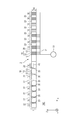
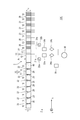
- FIG. 1 is a view of the chuck 1 as viewed from the + Z direction
- FIG. 2 is a view showing the configuration of the holding device 100 and includes a cross-sectional view taken along the line AA of the chuck 1.
- FIG. 3 is an enlarged view of the region 40 of FIG.
- the holding device 100 includes a chuck 1, an exhaust unit 30, and a pipe 31.
- the exhaust unit 30 exhausts the support unit 10 on the chuck 1, the chuck 1 sucks and holds the placed substrate.
- Three openings 30 are formed in the surface 2 of the chuck 1 that holds the substrate.
- the opening 30 is for a support pin (not shown) for temporarily supporting the substrate to protrude from the base portion 14 having the surface 2 when the substrate is carried into and out of the holding device 100.
- the chuck 1 is provided with support portions 10 protruding from the surface 2 and regions 20 alternately and concentrically.
- Each support portion 10 has four convex portions (contact portions) 11 that can come into contact with the substrate and three concave portions 13, and supports the concave portions 13 between two adjacent convex portions 11.
- the part is composed.
- the support portion 10 has a structure in which four convex portions 11 and three concave portions 13 are arranged in a direction (one direction) from the center of the chuck 1 toward the outer periphery of the chuck 1.
- the recesses 13 are continuously arranged in the direction toward the outer periphery (formed continuously without the region 20).
- the widths of the three recesses 13 can be arbitrarily set. For example, as shown in FIG. 3, the width b of the center recess 13 is wider than the widths a and c of the recesses 13 (other recesses) at both ends. It is preferable. Thereby, the deformation
- Each recess 13 has at least one opening 12, and at least three recesses 12 included in one support 10 are connected to a common exhaust 30. That is, the opening 12 is a common opening for the three recesses 13. In the present embodiment, all the openings 12 are connected to the common exhaust part 30.
- An exhaust part 30 for exhausting the recess 13 is provided via the opening 12 and the pipe 31.
- the exhaust unit 30 is, for example, a vacuum pump.
- the region 20 is a region between the support unit 10 and the support unit 10, and at least one opening 22 is provided in each region 20.
- the opening 22 is an opening through which a gas (such as air) in the atmosphere in which the chuck 1 is disposed can enter and exit.
- a gas such as air
- region 20 which is the side part space of the support part 10 (space between a 1st support part and a 2nd support part).
- the opening 22 may be connected to a gas supply portion that supplies a predetermined gas, or the pressure is adjusted. Gas may be supplied.
- the holding device 100 holds the unloaded substrate. Since the support portion 10 has a structure in which the four convex portions 11 and the concave portions 13 provided between the respective convex portions 11 are arranged in one direction, the flatness of the substrate in a state where the substrate is held can be obtained. Can be improved. In particular, even when the substrate is thin, the substrate can be held while maintaining high flatness.
- the chuck 1 is suitable for holding a special substrate that has been excavated, for example, until the thickness of the central portion becomes about 1/10 of the outer peripheral portion.
- Example 1 An example in which the substrate is held by the chuck 1 will be described using a comparative example.
- FIG. 4 is a cross-sectional view of the chuck 95, which is different from the chuck 1 in that the support portions 90 arranged at equal intervals have two convex portions 91 and one concave portion 93 therebetween.
- the support portion 90 is arranged concentrically like the chuck 1 when the chuck 95 is viewed from the + Z direction.
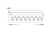
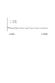
- FIG. 5A is a diagram showing a simulation result of the flatness of the substrate when the substrate is held using the chuck 95 according to the comparative example.
- FIG. 5B is a diagram showing a simulation result of the flatness of the substrate when the substrate is held using the chuck 1.
- the vertical axis represents the position in the height direction of the back surface of the substrate held by each chuck
- the horizontal axis represents the position in the radial direction of the chuck.
- the left end point of the horizontal axis is the center position of the chuck 1, and the right end point of the horizontal axis is the outer peripheral position.
- each chuck has eight support portions 10 or support portions 90.
- the other part of the inner part of the support part 90 closest to the center of the chuck 95 and the outer part of the support part 90 closest to the outer periphery of the chuck 95 In comparison, the position of the back side of the substrate was greatly raised. That is, the portion on the center side of the substrate and the portion on the outer peripheral side of the substrate are greatly deformed as compared with the other portions. Further, the position of the back surface of the substrate was also raised locally between the support portion 90 and the support portion 90.
- the substrate can be held with a flatness of 1/10 or less in the case of the chuck 1 compared to the case of the chuck 95. That is, the support 10 has a structure in which the four protrusions 11 and the recesses 13 provided between the protrusions 11 are arranged in one direction, whereby the plane of the substrate in a state where the substrate is held. It was confirmed that the degree could be improved.
- FIG. 6 is an enlarged view of a cross section of the chuck 1 according to the second embodiment.
- the same members as those in the first embodiment are denoted by the same reference numerals, and detailed description thereof is omitted.
- the chuck 1 according to the present embodiment is a support portion 10 in which one support portion 10 includes three recesses 13, and the other support portion 90 is a support portion having one recess 93. In this way, even if all the support portions that support the substrate do not have the three recessed portions 13 as in the support portion 10, at least one of the plurality of support portions has the three recessed portions 13. It only has to have. Even in the case of the present embodiment, the same effects as those of the first embodiment are obtained.
- the support portion closest to the center position P0 of the chuck 1 is preferably the support portion 10.
- FIG. 7 is a simulation result showing the position of the back surface of the substrate held by the chuck 1 according to the second embodiment. Except for changing the configuration of the chuck 1, the various conditions of the simulation and the configuration of the shaft are the same as described above, and thus detailed description thereof is omitted.
- the support portion 10 is disposed at a position closest to the center of the chuck 1, the deformation of the substrate in the central portion of the substrate, which has been noticeable in the comparative example described above, can be significantly reduced. I was able to. The substrate can be held with good flatness.
- the support portion closest to the center of the chuck 1 may be the support portion 10.
- the flatness of the substrate in a state where the substrate is held can be improved by using the support portion closest to the center of the chuck 1 and the support portion closest to the outer periphery of the chuck 1 as the support portion 10.
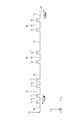
- FIG. 8 is a diagram illustrating a configuration of the holding device 300 according to the third embodiment, and includes a cross-sectional view of the chuck 1.
- the same members as those in the first embodiment are denoted by the same reference numerals, and detailed description thereof is omitted.
- the holding device 300 controls the evacuation means by the control unit 35, the adsorption pressure generated at the support unit 10 (part of the support unit) closest to the center position P 0 of the chuck 1, and the substrate generated at the other support units 10.
- the adsorption pressure is controlled individually.
- the holding device 300 includes an exhaust part 30, pipes 31a and 31b, pressure gauges 32a and 32b, electromagnetic valves 33a and 33b, and adjustment parts 34a and 34b as exhaust means.
- the pressure gauge 32a measures the pressure in the pipe 31a
- the pressure gauge 32b measures the pressure in the pipe 31b.
- the solenoid valve 33a switches ON / OFF of the exhaust of the pipe 31a
- the solenoid valve 33b switches ON / OFF of the exhaust of the pipe 31b.
- the adjusting unit 34a adjusts the pressure in the pipe 31a
- the adjusting unit 34b adjusts the pressure in the pipe 31a.
- the control unit 35 controls the electromagnetic valves 33a and 33b and the adjustment units 34a and 34b.
- control unit 35 controls the adjustment unit 34b so as to keep the inside of the pipe 31b at a predetermined pressure and variably controls only the pressure in the pipe 31a.
- FIG. 9 is a simulation result showing the position of the back surface of the substrate held by the chuck 1 according to the third embodiment.
- various simulation conditions and the configuration of the shaft are the same as described above, and thus detailed description thereof is omitted.
- the control unit 35 controls the pressure in the pipe 31a based on the flatness information at the center of the substrate.
- the solid line indicates the position in the height direction of the back surface of the substrate when the substrate is held at an adsorption pressure of 75 kPa in all the support portions 10.
- the broken line indicates the position in the height direction of the back surface of the substrate when the suction pressure generated at the support portion 10 closest to the center position P0 of the chuck 1 is reduced to 40 kPa.
- the suction force at the first support portion it is preferable to previously set the suction force at the first support portion to 75 kPa.
- the position of the back surface can be raised in advance as compared with the outer peripheral portion, and the flatness of the surface of the substrate can be increased.
- the holding device 300 has the same effect as that of the first embodiment. Furthermore, by controlling the position of the back surface of the substrate by controlling the pressure of the pipe 31a, it is possible to compensate for the deterioration in flatness due to the thickness distribution of the substrate.
- the controller 35 may acquire the flatness information based on the result of the thickness measurement using another measuring instrument before being carried into the holding device 300, or after being carried into the holding device 300.
- Flatness information may be acquired by measuring the position of the surface of the substrate using ultrasonic waves or light. Or you may acquire the information input from the user as flatness information of a board
- the control of the adsorption pressure by the control unit 35 includes ON / OFF of the exhaust by controlling the electromagnetic valves 33a and 33b.
- the piping 31b may also control the adsorption pressure continuously.
- FIG. 10 is an enlarged view when the chuck 1 according to the fourth embodiment is viewed from the + Z direction, and illustrates a portion including one support portion 10.
- the same members as those in the first embodiment are denoted by the same reference numerals, and detailed description thereof is omitted. Further, the three recesses 13 may be exhausted by one opening 12.
- the support portion 10 may have a structure in which the three convex portions 11 and the two concave portions 13 are arranged in one direction. Good.
- the one or more support portions 10 have a structure in which three convex portions 11 and two concave portions 13 are arranged in one direction.
- the support part 10 may be the support part 10 except for the support part closest to the center of the chuck 1 and the support part closest to the outer periphery of the chuck 1. .
- the flatness of the substrate in a state where the substrate is held can be improved as compared with the case of the chuck 95.
- FIG. 11 is a diagram showing a configuration of an exposure apparatus 600 as the lithography apparatus.
- An axis parallel to the optical axis of the projection optical system 604 (vertical direction in this embodiment) is taken as the Z axis.
- the directions perpendicular to each other in a plane perpendicular to the Z axis are taken as an X axis and a Y axis.
- the exposure apparatus 600 illuminates a reticle (original) 602 with illumination light 603 via an illumination optical system 601, and projects an image of a pattern formed on the illuminated reticle 602 onto a substrate 605 via a projection optical system 604. To do.
- the stage 606 holds the reticle 602 and scans in the X-axis direction.
- the stage 607 moves the chuck 1 and the substrate 605 held by the chuck 1 by a drive mechanism (not shown) such as a linear motor.
- the exposure apparatus 600 forms a latent image pattern on the resist applied to the substrate 605 while relatively scanning the reticle 602 and the substrate 605 with the stages 606 and 607.
- the interferometer 608 irradiates the mirror 609 with the laser light and the interferometer 610 irradiates the mirror 611 with laser light, and receives the reflected light to detect the position of the reticle 602 and the substrate 605.
- the detection system 612 detects an alignment mark (not shown) formed on the substrate 605 and a reference mark (not shown) provided on the stage 607.
- the holding device 100 includes a top plate 614 having a built-in pin 613 that supports the substrate 605 when the substrate 605 is carried in and out, and a lifting mechanism (not configured) that moves the chuck 1 and the top plate 614 up and down with respect to the pin 613. As shown).
- the control unit 615 is connected to the stages 606 and 607, the detection system 612, the interferometers 608 and 610, and the holding device 100, and comprehensively controls them. For example, at the time of exposure processing, a pattern formation position is determined based on the detection result of the detection system 612, and the stages 606 and 607 are controlled based on position information obtained from the interferometers 608 and 610.
- the controller 615 controls the lifting mechanism of the holding device 100 and the movement of the stage 607 when the substrate 605 is carried in and out.
- the control unit 615 may be configured in a casing that accommodates components other than the control unit 615, or may be configured in a casing different from the casing.
- the flatness of the substrate 605 can be improved as compared with the case of holding with a holding device using a supporting member that does not have the three concave portions 13. Therefore, it becomes easy to perform exposure while aligning the position of the surface of the substrate 605 with the focus position of the exposure light 616. Thereby, degradation of the resolution line width of the pattern formed on the substrate 605, which may occur when the flatness of the substrate 605 is poor, can be reduced.
- the chuck 1 and the holding apparatuses 100 and 300 according to the second to fifth embodiments may be mounted.
- Light that the exposure apparatus 600 irradiates the substrate 605 is not limited to i-line (wavelength 365 nm), but light in the far ultraviolet region such as KrF light (wavelength 248 nm) and ArF light (wavelength 193 nm), g-line. Light in the visible light region such as (wavelength 436 nm) may be used.
- the lithography apparatus according to the embodiment of the present invention may be an apparatus that forms a resist (imprint material) pattern on a substrate by an imprint method, or the substrate is irradiated with a laser beam or a charged particle beam to be latent on the wafer. An apparatus for drawing an image pattern may be used.
- the shape of the support portion 10 of the chuck 1 does not necessarily have to be a continuous circle (annular). A single rectangle (rectangular ring) may be used.
- FIG. 1 shows a case where the support portions 10 are concentric, that is, a plurality of annular support portions 10 are arranged in multiple directions along the substrate held by the chuck 1, Also good.
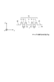
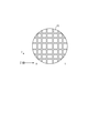
- the shape of the support part 10 may be a combination of a linear support part 10 or a linear support part 10 that partitions the surface 2 into a plurality of rectangular regions, as shown in FIG. A combination of the linear support portion 10 and the annular support portion 10 may be used.
- illustration of the recessed part 13 and the opening 12 contained in the support part 10 is abbreviate
- the support portions 10 may be arranged so as to be multiplexed along the surface of the substrate held by the chuck 1.
- the support portion 10 may be integrally formed with the base portion 14 constituting the surface 2 or may be provided separately from the base portion 14.
- the height of the bottom of the recess 13 may be the same height as the surface 2 or higher than the surface 2.
- the third embodiment may be appropriately combined with the chuck 1 shown in the other embodiments.
- the arrangement of the openings 12 shown in the fourth embodiment may be implemented in combination with the chuck 1 shown in other embodiments as appropriate.
- a pattern formed on a substrate using a lithography apparatus is temporarily used when various articles are manufactured.
- the article is an electric circuit element, an optical element, a MEMS, a recording element, a sensor, or a mold.
- the electric circuit elements include volatile or nonvolatile semiconductor memories such as DRAM, SRAM, flash memory, and MRAM, and semiconductor elements such as LSI, CCD, image sensor, and FPGA.
- the mold include an imprint mold.
- the pattern formed using the lithography apparatus is subjected to etching or ion implantation in the substrate processing step, and then the resist used as a mask is removed.
- the resist is developed before the above-described processing steps.
- the resist cured pattern formed by using an imprint apparatus as a lithography apparatus may be used as a constituent member of at least a part of the article.
Landscapes
- Physics & Mathematics (AREA)
- General Physics & Mathematics (AREA)
- Container, Conveyance, Adherence, Positioning, Of Wafer (AREA)
- Exposure And Positioning Against Photoresist Photosensitive Materials (AREA)
- Shaping Of Tube Ends By Bending Or Straightening (AREA)
Abstract
Selon un mode de réalisation de la présente invention, un mandrin comprend une partie de base sur laquelle sont ménagées une première et une seconde partie de support (10) comportant chacune une structure répétée composée d'une saillie (11) et d'un évidement (13). Le mandrin maintient un substrat lorsque la saillie (11) appuie contre le substrat et l'évidement (13) est évacué afin de produire une pression négative dans l'évidement (13) par rapport à un espace entre la première partie de support (10) et la seconde partie de support (10). Le mandrin est caractérisé en ce qu'au moins une de la première partie de support (10) et de la seconde partie de support (10) comporte au moins quatre saillies (11) et trois évidements (13).
Priority Applications (5)
| Application Number | Priority Date | Filing Date | Title |
|---|---|---|---|
| EP17806606.4A EP3467870B1 (fr) | 2016-06-01 | 2017-05-29 | Mandrin, dispositif de support de substrat, dispositif de formation de motif et procédé de fabrication d'article |
| KR1020187038187A KR102169894B1 (ko) | 2016-06-01 | 2017-05-29 | 척, 기판 보유 지지 장치, 패턴 형성 장치, 및 물품의 제조 방법 |
| SG11201810641UA SG11201810641UA (en) | 2016-06-01 | 2017-05-29 | Chuck, substrate-holding apparatus, pattern-forming apparatus, and method of manufacturing article |
| CN201780033601.4A CN109314077B (zh) | 2016-06-01 | 2017-05-29 | 吸盘、基板保持设备、图案形成设备和制造物品的方法 |
| US16/204,563 US10754262B2 (en) | 2016-06-01 | 2018-11-29 | Chuck, substrate-holding apparatus, pattern-forming apparatus, and method of manufacturing article |
Applications Claiming Priority (2)
| Application Number | Priority Date | Filing Date | Title |
|---|---|---|---|
| JP2016109651A JP6758920B2 (ja) | 2016-06-01 | 2016-06-01 | チャック、基板保持装置、パターン形成装置、及び物品の製造方法 |
| JP2016-109651 | 2016-06-01 |
Related Child Applications (1)
| Application Number | Title | Priority Date | Filing Date |
|---|---|---|---|
| US16/204,563 Continuation US10754262B2 (en) | 2016-06-01 | 2018-11-29 | Chuck, substrate-holding apparatus, pattern-forming apparatus, and method of manufacturing article |
Publications (1)
| Publication Number | Publication Date |
|---|---|
| WO2017209051A1 true WO2017209051A1 (fr) | 2017-12-07 |
Family
ID=60477425
Family Applications (1)
| Application Number | Title | Priority Date | Filing Date |
|---|---|---|---|
| PCT/JP2017/019917 Ceased WO2017209051A1 (fr) | 2016-06-01 | 2017-05-29 | Mandrin, dispositif de support de substrat, dispositif de formation de motif et procédé de fabrication d'article |
Country Status (8)
| Country | Link |
|---|---|
| US (1) | US10754262B2 (fr) |
| EP (1) | EP3467870B1 (fr) |
| JP (1) | JP6758920B2 (fr) |
| KR (1) | KR102169894B1 (fr) |
| CN (1) | CN109314077B (fr) |
| SG (1) | SG11201810641UA (fr) |
| TW (1) | TWI648815B (fr) |
| WO (1) | WO2017209051A1 (fr) |
Cited By (1)
| Publication number | Priority date | Publication date | Assignee | Title |
|---|---|---|---|---|
| US20210125855A1 (en) * | 2019-10-29 | 2021-04-29 | Canon Kabushiki Kaisha | Superstrate chuck, method of use, and method of manufacturing an article |
Families Citing this family (5)
| Publication number | Priority date | Publication date | Assignee | Title |
|---|---|---|---|---|
| CN107604309B (zh) * | 2017-11-06 | 2023-09-15 | 京东方科技集团股份有限公司 | 掩膜板贴合装置以及其贴合方法 |
| KR102628919B1 (ko) * | 2019-05-29 | 2024-01-24 | 주식회사 원익아이피에스 | 기판처리장치 및 이를 이용한 기판처리방법 |
| US11728204B2 (en) * | 2020-10-23 | 2023-08-15 | Kla Corporation | High flow vacuum chuck |
| US11794314B2 (en) | 2021-08-30 | 2023-10-24 | Kla Corporation | Quick swap chuck with vacuum holding interchangeable top plate |
| KR102413824B1 (ko) * | 2022-01-04 | 2022-06-28 | 주식회사 메이코리아 | 진공압을 이용해 피가공물을 회전 가능하게 고정하는 고정용 지그 |
Citations (5)
| Publication number | Priority date | Publication date | Assignee | Title |
|---|---|---|---|---|
| JPH045646U (fr) * | 1990-04-27 | 1992-01-20 | ||
| JPH05235151A (ja) * | 1992-02-20 | 1993-09-10 | Canon Inc | 基板保持盤 |
| JPH0831719A (ja) * | 1994-07-13 | 1996-02-02 | Nikon Corp | 半導体基板用吸着ホルダー及び投影露光装置 |
| JPH0851143A (ja) * | 1992-07-20 | 1996-02-20 | Nikon Corp | 基板保持装置 |
| JP2015038982A (ja) * | 2013-07-18 | 2015-02-26 | Nskテクノロジー株式会社 | 基板の保持装置及び密着露光装置並びに近接露光装置 |
Family Cites Families (23)
| Publication number | Priority date | Publication date | Assignee | Title |
|---|---|---|---|---|
| DE69133413D1 (de) * | 1990-05-07 | 2004-10-21 | Canon Kk | Substratträger des Vakuumtyps |
| JPH0521584A (ja) * | 1991-07-16 | 1993-01-29 | Nikon Corp | 保持装置 |
| JPH06196381A (ja) | 1992-12-22 | 1994-07-15 | Canon Inc | 基板保持装置 |
| JP3487368B2 (ja) * | 1994-09-30 | 2004-01-19 | 株式会社ニコン | 走査型露光装置 |
| US5923408A (en) * | 1996-01-31 | 1999-07-13 | Canon Kabushiki Kaisha | Substrate holding system and exposure apparatus using the same |
| JP2821678B2 (ja) * | 1997-04-07 | 1998-11-05 | 株式会社ニコン | 基板の吸着装置 |
| JP2000100895A (ja) * | 1998-09-18 | 2000-04-07 | Nikon Corp | 基板の搬送装置、基板の保持装置、及び基板処理装置 |
| KR100804006B1 (ko) * | 2000-01-28 | 2008-02-18 | 히다치 도쿄 에렉트로닉스 가부시키가이샤 | 웨이퍼 척 |
| JP3859937B2 (ja) * | 2000-06-02 | 2006-12-20 | 住友大阪セメント株式会社 | 静電チャック |
| EP1458019A3 (fr) * | 2003-03-13 | 2005-12-28 | VenTec Gesellschaft für Venturekapital und Unternehmensberatung | Porte-substrats mobiles électrostatiques et transportables |
| EP1491953A1 (fr) * | 2003-06-23 | 2004-12-29 | ASML Netherlands B.V. | Appareil lithographique, procédé pour la production d'un dispositif et dispositif produit par ce procédé |
| JP4229380B2 (ja) * | 2003-09-30 | 2009-02-25 | コバレントマテリアル株式会社 | 基板保持用真空チャック |
| KR101281397B1 (ko) * | 2003-12-15 | 2013-07-02 | 가부시키가이샤 니콘 | 스테이지 장치, 노광 장치, 및 노광 방법 |
| CN103558737A (zh) * | 2004-06-09 | 2014-02-05 | 尼康股份有限公司 | 基板保持装置、具备其之曝光装置、方法 |
| US8102512B2 (en) * | 2004-09-17 | 2012-01-24 | Nikon Corporation | Substrate holding device, exposure apparatus, and device manufacturing method |
| KR100689843B1 (ko) * | 2006-01-03 | 2007-03-08 | 삼성전자주식회사 | 웨이퍼 스테이지 및 이를 이용한 웨이퍼 안착방법 |
| JPWO2007083592A1 (ja) * | 2006-01-17 | 2009-06-11 | 株式会社ニコン | 基板保持装置及び露光装置、並びにデバイス製造方法 |
| US7791708B2 (en) * | 2006-12-27 | 2010-09-07 | Asml Netherlands B.V. | Lithographic apparatus, substrate table, and method for enhancing substrate release properties |
| US9013682B2 (en) * | 2007-06-21 | 2015-04-21 | Asml Netherlands B.V. | Clamping device and object loading method |
| US8540819B2 (en) * | 2008-03-21 | 2013-09-24 | Ngk Insulators, Ltd. | Ceramic heater |
| US8336188B2 (en) * | 2008-07-17 | 2012-12-25 | Formfactor, Inc. | Thin wafer chuck |
| KR20140124948A (ko) * | 2013-04-16 | 2014-10-28 | 주식회사 월덱스 | 평탄도 유지와 치핑방지에 용이한 반도체 제조설비용 진공 척 |
| JP6706182B2 (ja) * | 2016-09-16 | 2020-06-03 | キオクシア株式会社 | 基板保持装置 |
-
2016
- 2016-06-01 JP JP2016109651A patent/JP6758920B2/ja active Active
-
2017
- 2017-05-29 KR KR1020187038187A patent/KR102169894B1/ko active Active
- 2017-05-29 SG SG11201810641UA patent/SG11201810641UA/en unknown
- 2017-05-29 WO PCT/JP2017/019917 patent/WO2017209051A1/fr not_active Ceased
- 2017-05-29 CN CN201780033601.4A patent/CN109314077B/zh active Active
- 2017-05-29 EP EP17806606.4A patent/EP3467870B1/fr active Active
- 2017-06-01 TW TW106118127A patent/TWI648815B/zh active
-
2018
- 2018-11-29 US US16/204,563 patent/US10754262B2/en active Active
Patent Citations (5)
| Publication number | Priority date | Publication date | Assignee | Title |
|---|---|---|---|---|
| JPH045646U (fr) * | 1990-04-27 | 1992-01-20 | ||
| JPH05235151A (ja) * | 1992-02-20 | 1993-09-10 | Canon Inc | 基板保持盤 |
| JPH0851143A (ja) * | 1992-07-20 | 1996-02-20 | Nikon Corp | 基板保持装置 |
| JPH0831719A (ja) * | 1994-07-13 | 1996-02-02 | Nikon Corp | 半導体基板用吸着ホルダー及び投影露光装置 |
| JP2015038982A (ja) * | 2013-07-18 | 2015-02-26 | Nskテクノロジー株式会社 | 基板の保持装置及び密着露光装置並びに近接露光装置 |
Non-Patent Citations (1)
| Title |
|---|
| See also references of EP3467870A4 * |
Cited By (2)
| Publication number | Priority date | Publication date | Assignee | Title |
|---|---|---|---|---|
| US20210125855A1 (en) * | 2019-10-29 | 2021-04-29 | Canon Kabushiki Kaisha | Superstrate chuck, method of use, and method of manufacturing an article |
| US11776840B2 (en) * | 2019-10-29 | 2023-10-03 | Canon Kabushiki Kaisha | Superstrate chuck, method of use, and method of manufacturing an article |
Also Published As
| Publication number | Publication date |
|---|---|
| EP3467870B1 (fr) | 2022-07-27 |
| SG11201810641UA (en) | 2018-12-28 |
| CN109314077B (zh) | 2023-06-02 |
| JP6758920B2 (ja) | 2020-09-23 |
| JP2017216375A (ja) | 2017-12-07 |
| EP3467870A1 (fr) | 2019-04-10 |
| EP3467870A4 (fr) | 2020-02-26 |
| US20190094700A1 (en) | 2019-03-28 |
| KR20190015414A (ko) | 2019-02-13 |
| US10754262B2 (en) | 2020-08-25 |
| TWI648815B (zh) | 2019-01-21 |
| KR102169894B1 (ko) | 2020-10-26 |
| TW201743405A (zh) | 2017-12-16 |
| CN109314077A (zh) | 2019-02-05 |
Similar Documents
| Publication | Publication Date | Title |
|---|---|---|
| JP7068378B2 (ja) | 基板ホルダ、リソグラフィ装置およびデバイス製造方法 | |
| US6875987B2 (en) | Substrate holding unit, exposure apparatus, and device manufacturing method | |
| WO2017209051A1 (fr) | Mandrin, dispositif de support de substrat, dispositif de formation de motif et procédé de fabrication d'article | |
| JP6708455B2 (ja) | 保持装置、保持方法、リソグラフィ装置、および物品の製造方法 | |
| CN106255924B (zh) | 衬底支座、用于在衬底支撑位置上加载衬底的方法、光刻设备和器件制造方法 | |
| TWI780501B (zh) | 基板台及微影裝置 | |
| US9939736B2 (en) | Substrate holder and support table for lithography | |
| JP6676197B2 (ja) | ステージシステム、リソグラフィ装置およびデバイス製造方法 | |
| JP2018531408A6 (ja) | 基板テーブル及びリソグラフィ装置 | |
| JP5134705B2 (ja) | 物体の非接触ハンドリング装置および方法 | |
| JP2018529995A (ja) | 基板ホルダ、リソグラフィ装置、及びデバイスを製造する方法 | |
| TWI463274B (zh) | 微影裝置及基板處置方法 | |
| JP4833953B2 (ja) | リソグラフィ装置およびデバイス製造方法 | |
| JP2017175070A (ja) | 保持装置、保持方法、リソグラフィ装置、および物品の製造方法 | |
| JP2006041012A (ja) | ステージ装置、露光装置、及び露光方法 | |
| JP2017139455A (ja) | パターン形成方法および物品製造方法 |
Legal Events
| Date | Code | Title | Description |
|---|---|---|---|
| NENP | Non-entry into the national phase |
Ref country code: DE |
|
| 121 | Ep: the epo has been informed by wipo that ep was designated in this application |
Ref document number: 17806606 Country of ref document: EP Kind code of ref document: A1 |
|
| ENP | Entry into the national phase |
Ref document number: 20187038187 Country of ref document: KR Kind code of ref document: A |
|
| ENP | Entry into the national phase |
Ref document number: 2017806606 Country of ref document: EP Effective date: 20190102 |