WO2018123232A1 - トーンアームユニット及び再生装置 - Google Patents
トーンアームユニット及び再生装置 Download PDFInfo
- Publication number
- WO2018123232A1 WO2018123232A1 PCT/JP2017/038117 JP2017038117W WO2018123232A1 WO 2018123232 A1 WO2018123232 A1 WO 2018123232A1 JP 2017038117 W JP2017038117 W JP 2017038117W WO 2018123232 A1 WO2018123232 A1 WO 2018123232A1
- Authority
- WO
- WIPO (PCT)
- Prior art keywords
- lock
- cam
- arm unit
- tone arm
- rotation
- Prior art date
- Legal status (The legal status is an assumption and is not a legal conclusion. Google has not performed a legal analysis and makes no representation as to the accuracy of the status listed.)
- Ceased
Links
Images






Classifications
-
- G—PHYSICS
- G11—INFORMATION STORAGE
- G11B—INFORMATION STORAGE BASED ON RELATIVE MOVEMENT BETWEEN RECORD CARRIER AND TRANSDUCER
- G11B3/00—Recording by mechanical cutting, deforming or pressing, e.g. of grooves or pits; Reproducing by mechanical sensing; Record carriers therefor
- G11B3/02—Arrangements of heads
- G11B3/08—Raising, lowering, traversing otherwise than for transducing, arresting, or holding-up heads against record carriers
-
- G—PHYSICS
- G11—INFORMATION STORAGE
- G11B—INFORMATION STORAGE BASED ON RELATIVE MOVEMENT BETWEEN RECORD CARRIER AND TRANSDUCER
- G11B3/00—Recording by mechanical cutting, deforming or pressing, e.g. of grooves or pits; Reproducing by mechanical sensing; Record carriers therefor
- G11B3/02—Arrangements of heads
- G11B3/08—Raising, lowering, traversing otherwise than for transducing, arresting, or holding-up heads against record carriers
- G11B3/085—Raising, lowering, traversing otherwise than for transducing, arresting, or holding-up heads against record carriers using automatic means
- G11B3/08503—Control of drive of the head
- G11B3/08506—Control of drive of the head for pivoting pick-up arms
- G11B3/08509—Control of drive of the head for pivoting pick-up arms using mechanical detecting means
-
- G—PHYSICS
- G11—INFORMATION STORAGE
- G11B—INFORMATION STORAGE BASED ON RELATIVE MOVEMENT BETWEEN RECORD CARRIER AND TRANSDUCER
- G11B3/00—Recording by mechanical cutting, deforming or pressing, e.g. of grooves or pits; Reproducing by mechanical sensing; Record carriers therefor
- G11B3/02—Arrangements of heads
- G11B3/08—Raising, lowering, traversing otherwise than for transducing, arresting, or holding-up heads against record carriers
- G11B3/085—Raising, lowering, traversing otherwise than for transducing, arresting, or holding-up heads against record carriers using automatic means
- G11B3/08535—Driving the head
- G11B3/08564—Driving the head the head being driven by means independent of the record carrier driving means
- G11B3/08567—Driving the head the head being driven by means independent of the record carrier driving means for pivoting pick-up arms
- G11B3/0857—Driving the head the head being driven by means independent of the record carrier driving means for pivoting pick-up arms driven by means which support the pick-up arm
-
- G—PHYSICS
- G11—INFORMATION STORAGE
- G11B—INFORMATION STORAGE BASED ON RELATIVE MOVEMENT BETWEEN RECORD CARRIER AND TRANSDUCER
- G11B3/00—Recording by mechanical cutting, deforming or pressing, e.g. of grooves or pits; Reproducing by mechanical sensing; Record carriers therefor
- G11B3/02—Arrangements of heads
- G11B3/08—Raising, lowering, traversing otherwise than for transducing, arresting, or holding-up heads against record carriers
- G11B3/09—Raising, lowering, traversing otherwise than for transducing, arresting, or holding-up heads against record carriers using manual means only
- G11B3/092—Raising, lowering, traversing otherwise than for transducing, arresting, or holding-up heads against record carriers using manual means only using mechanical means
-
- G—PHYSICS
- G11—INFORMATION STORAGE
- G11B—INFORMATION STORAGE BASED ON RELATIVE MOVEMENT BETWEEN RECORD CARRIER AND TRANSDUCER
- G11B3/00—Recording by mechanical cutting, deforming or pressing, e.g. of grooves or pits; Reproducing by mechanical sensing; Record carriers therefor
- G11B3/02—Arrangements of heads
- G11B3/10—Arranging, supporting, or driving of heads or of transducers relatively to record carriers
- G11B3/30—Supporting in an inoperative position
- G11B3/32—Construction or arrangement of support pillars
-
- G—PHYSICS
- G11—INFORMATION STORAGE
- G11B—INFORMATION STORAGE BASED ON RELATIVE MOVEMENT BETWEEN RECORD CARRIER AND TRANSDUCER
- G11B3/00—Recording by mechanical cutting, deforming or pressing, e.g. of grooves or pits; Reproducing by mechanical sensing; Record carriers therefor
- G11B3/60—Turntables for record carriers
Definitions
- the present disclosure relates to a tone arm unit and a playback apparatus including the tone arm unit.
- the playback device is equipped with a tone arm unit for picking up an audio signal from a record board (see, for example, Patent Document 1).
- the tone arm unit includes a main body member, a base member disposed on the main body member, and an arm member supported by the base member.
- a cartridge having a record needle is detachably attached to the tip of the arm member.
- the conventional tone arm unit is equipped with a lifting mechanism for adjusting the height position of the arm member from the record board so that the posture of the arm member is substantially horizontal.
- the elevating mechanism has an adjustment ring that is rotatably disposed between the base member and the main body member.
- Each of the inner surface of the adjustment ring and the outer surface of the base member is formed with a six-thread screw, and these six-thread screws are meshed with each other.
- the present disclosure provides a tone arm unit and a playback device in which an elevating mechanism can be easily incorporated.
- a tone arm unit is a tone arm unit used in a reproducing apparatus for reproducing a record board, and includes an arm member for attaching a cartridge to a tip portion, and the arm member along a predetermined axis with respect to the record board.
- a first guide portion that extends while inclining along the rotation direction of the rotation member, and is formed on the rotation member so as to face the first guide portion and incline along the rotation direction.
- a second guide portion extending while the support member is slid along the first guide portion when the rotation member rotates relative to the support member. By It moves up and down relative to the moving member.
- the lifting mechanism can be easily incorporated.
- FIG. 1 is a perspective view showing a playback apparatus according to the first embodiment.
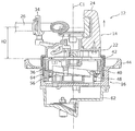
- FIG. 2 is a perspective view showing the tone arm unit according to the first embodiment.
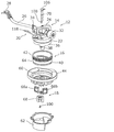
- FIG. 3 is an exploded perspective view showing the tone arm unit according to the first embodiment.
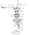
- 4 is an exploded perspective view showing the tone arm unit according to the first embodiment in a state viewed from an angle different from that in FIG.
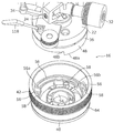
- FIG. 5 is an exploded perspective view showing the lifting mechanism according to the first embodiment.
- FIG. 6 is an exploded perspective view showing the lifting mechanism according to the first embodiment when viewed from an angle different from that in FIG. 5.
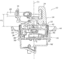
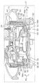
- 7A is a cross-sectional view taken along line VII-VII in FIG. 2 in a state where the arm member is lowered most.
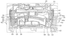
- FIG. 7B is an enlarged cross-sectional perspective view showing a part of FIG. 7A.
- FIG. 8A is a cross-sectional view taken along line VII-VII in FIG. 2 in a state where the arm member is raised most.
- FIG. 8B is a cross-sectional perspective view showing a part of FIG. 8A in an enlarged manner.
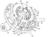
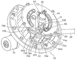
- FIG. 9 is a perspective view showing the lock mechanism according to the first embodiment.
- FIG. 10 is a perspective view showing the lock mechanism according to the first embodiment in a state where the lock plate is omitted.
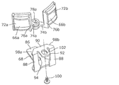
- FIG. 11 is a perspective view showing a part of the lock mechanism according to the first embodiment.
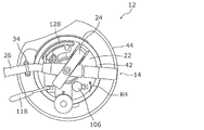
- FIG. 12A is a plan view showing the tone arm unit according to Embodiment 1 in a state where each of the pair of lock supports is located at a release position.
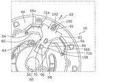
- FIG. 12B is an enlarged view of a part of the lock mechanism according to Embodiment 1 in a state where each of the pair of lock supports is located at the release position.
- 12C is a cross-sectional view taken along the line XII-XII of FIG. 9 in a state where each of the pair of lock supports is located at the release position.
- FIG. 13A is a plan view showing the tone arm unit according to Embodiment 1 in a state where each of the pair of lock supports is located at the lock position.
- FIG. 14A is a perspective view showing the lifter mechanism according to Embodiment 1 in a state where the mounting table is located at the upper limit position.
- FIG. 14B is a side view showing the lifter mechanism according to Embodiment 1 in a state where the mounting table is located at the upper limit position.
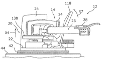
- FIG. 14C is a side view showing the tone arm unit according to Embodiment 1 in a state where the mounting table is located at the upper limit position.
- FIG. 15A is a perspective view showing the lifter mechanism according to Embodiment 1 in a state where the mounting table is located at the lower limit position.
- FIG. 15B is a side view showing the lifter mechanism according to Embodiment 1 in a state where the mounting table is located at the lower limit position.
- FIG. 15C is a side view showing the tone arm unit according to Embodiment 1 in a state where the mounting table is located at the lower limit position.
- FIG. 16 is a perspective view showing a lock mechanism according to the second embodiment.
- FIG. 17 is a perspective view showing the lock mechanism according to the second embodiment in a state where a pair of lock supports, a lock plate, and the like are omitted.
- FIG. 18 is a perspective view showing a part of the lock mechanism according to the second embodiment.
- FIG. 19 is a perspective view showing the lock mechanism according to Embodiment 2 in a state where each of the pair of lock supports is located at the release position.
- FIG. 20 is a perspective view showing the lock mechanism according to Embodiment 2 in a state where each of the pair of lock supports is located at the lock position.
- FIG. 1 is a perspective view showing a playback apparatus 2 according to the first embodiment.
- the playback device 2 is a device for playing back a record board 4 (so-called record player).
- the playback device 2 includes a housing 6, a turntable 8, a drive source 10, and a tone arm unit 12.
- the housing 6 has a substantially rectangular box shape in plan view.
- the turntable 8 is a disk-like table on which the record board 4 is placed, and is rotatably supported on the upper surface of the housing 6.
- the drive source 10 is a motor for rotating the turntable 8 and is disposed inside the housing 6.
- the tone arm unit 12 is a unit for picking up an audio signal from the record board 4 mounted on the turntable 8 that rotates, and is disposed adjacent to the turntable 8 on the upper surface of the housing 6.
- the reproduction apparatus 2 of the present embodiment is characterized by the configuration of the tone arm unit 12.
- the configuration of the tone arm unit 12 will be described in detail.
- FIG. 2 is a perspective view showing the tone arm unit 12 according to the first embodiment.
- FIG. 3 is an exploded perspective view showing the tone arm unit 12 according to the first embodiment.
- 4 is an exploded perspective view showing the tone arm unit 12 according to the first embodiment when viewed from an angle different from that in FIG.
- the tone arm unit 12 includes a tone arm unit 14, an elevating mechanism 16, a lock mechanism 18, and a lifter mechanism 20.
- a tone arm unit 14 an elevating mechanism 16
- a lock mechanism 18 a lock mechanism 18
- a lifter mechanism 20 a lifter mechanism 20
- tone arm unit 14 will be described with reference to FIGS.
- the tone arm unit 14 includes an arm base 22, a support mechanism 24, and an arm member 26.
- the arm base 22 is a member for supporting the arm member 26 and the like, and is formed in a circular shape in plan view.
- the support mechanism 24 is a mechanism for supporting the base end portion of the arm member 26 so as to be swingable in the horizontal direction and the vertical direction, and is disposed on the upper surface of the arm base 22.
- the arm member 26 extends in a long shape while being bent in a substantially S shape within a horizontal plane.
- a head shell 28 is supported at the tip of the arm member 26.
- a cartridge 30 (see FIG. 1) having a record needle is detachably attached to the head shell 28.
- a balance weight 32 for supporting a weight balance with the head shell 28 is supported at the base end portion of the arm member 26.
- the user When the record board 4 is not reproduced, the user supports the arm member 26 on a hook-shaped armrest 34 disposed on the upper surface of the arm base 22.
- the user When playing back the record board 4, after the user removes the arm member 26 from the arm rest 34, the user places the arm member 26 on a mounting table 128 (described later) while swinging the arm member 26 in the horizontal direction and the vertical direction. .
- the mounting table 128 As will be described later, when the mounting table 128 is lowered while the arm member 26 is mounted, the head shell 28 approaches the record board 4 on the turntable 8, and the record needle of the cartridge 30 moves through the groove of the record board 4. Trace.
- FIG. 5 is an exploded perspective view showing the lifting mechanism 16 according to the first embodiment.
- 6 is an exploded perspective view showing the lifting mechanism 16 according to the first embodiment when viewed from an angle different from that in FIG. 7A is a cross-sectional view taken along line VII-VII in FIG. 2 in a state where the arm member 26 is lowered most.
- FIG. 7B is an enlarged cross-sectional perspective view showing a part of FIG. 7A.
- the elevating mechanism 16 is a mechanism for elevating and lowering the arm member 26 with respect to the record board 4 on the turntable 8. As shown in FIGS. 3 and 4, the elevating mechanism 16 includes a cam base 36 (an example of a support member), a center shaft 38, a ring cam 40 (an example of a rotating member), an operation ring 42, and an arm base mount 44. And have.
- the cam base 36 is formed in a disc shape, and is fixed to the lower surface of the arm base 22 with a plurality of screws 46. That is, the cam base 36 supports the arm member 26 via the arm base 22.
- a plurality (three in the present embodiment) of first guide portions 48 are formed on the outer peripheral portion of the lower surface of the cam base 36.
- the plurality of first guide portions 48 are arranged side by side along the rotation direction of the ring cam 40 (that is, the circumferential direction of the cam base 36).
- Each of the plurality of first guide portions 48 extends while inclining along the rotation direction of the ring cam 40. That is, each of the plurality of first guide portions 48 extends in an arc shape while being inclined upward from the peak portion 48a to the valley portion 48b.
- a plurality (three in this embodiment) of protrusions 50 are formed on the outer peripheral portion of the lower surface of the cam base 36.
- the plurality of protrusions 50 extend vertically downward from the lower surface of the cam base 36 and are arranged at intervals along the rotational direction of the ring cam 40.
- a screw hole 50 a for screwing a retaining screw 52 is formed at the tip of each of the plurality of protrusions 50.
- the center shaft 38 is formed in a columnar shape, and extends vertically downward from the center portion on the lower surface of the cam base 36.
- a center axis C1 (an example of a predetermined axis) of the center shaft 38 extends in the vertical direction, and functions as a lift axis when the cam base 36 moves up and down with respect to the ring cam 40 as described later. Further, the center axis C1 of the center shaft 38 also functions as a rotation axis when the ring cam 40 rotates with respect to the cam base 36, as will be described later.
- the center shaft 38 is formed of a metal such as free-cutting steel or brass, for example.
- the ring cam 40 is formed in a bottomed cylindrical shape, and is disposed at a position covering the outer surface and the lower surface of the cam base 36.
- a circular hole 54 through which the center shaft 38 is inserted is formed at the center of the bottom of the ring cam 40.
- the ring cam 40 is rotatable with respect to the cam base 36 around the central axis C1 of the center shaft 38.
- a plurality (three in this embodiment) of second guide portions 56 are formed on the outer peripheral portion of the top surface of the bottom portion of the ring cam 40.
- the plurality of second guide portions 56 are arranged side by side along the rotation direction of the ring cam 40 (that is, the circumferential direction of the ring cam 40) corresponding to the plurality of first guide portions 48, respectively.
- Each of the plurality of second guide portions 56 extends so as to face the corresponding first guide portion 48 and incline along the rotation direction of the ring cam 40. That is, each of the plurality of second guide portions 56 extends in an arc shape while being inclined upward from the valley portion 56b to the peak portion 56a.
- the plurality of second guide portions 56 are close to the plurality of first guide portions 48, and the first guide portion 48 and the second guide portion 56 are connected to each other. For example, a gap of about 0.1 mm is formed between them.
- a plurality (three in the present embodiment) of groove portions 58 are formed on the outer peripheral portion of the bottom portion of the ring cam 40.
- the plurality of groove portions 58 are respectively arranged at intervals along the rotation direction of the ring cam 40 corresponding to the plurality of second guide portions 56.
- Each of the plurality of groove portions 58 extends in an arc shape along the corresponding second guide portion 56.
- a plurality of protrusions 50 of the cam base 36 are movably inserted into the plurality of grooves 58, respectively. As shown in FIGS.
- a retaining screw 52 is screwed into each screw hole 50a of each of the plurality of protrusions 50 via a cam spacer 59 (an example of a retaining member). That is, the cam spacer 59 is attached to the tip of the protrusion 50 by the retaining screw 52.
- the retaining screw 52 and the cam spacer 59 are disposed on the opposite side of the cam base 36 with the groove 58 interposed therebetween.
- the cam spacer 59 is wider than the groove 58.
- the operation ring 42 is attached to the outer surface of the upper end portion of the ring cam 40.
- the user can rotate the ring cam 40 relative to the cam base 36 by grasping the operation ring 42 with fingers.
- the arm base mount 44 is formed in a bottomed cylindrical shape, and is disposed at a position covering the outer surface of the ring cam 40 and the lower surface of the bottom portion.
- a circular hole 60 through which the center shaft 38 is inserted is formed at the center of the bottom of the arm base mount 44.
- a ring cam 40 is rotatably supported on the upper surface of the bottom of the arm base mount 44.
- the arm base mount 44 is made of metal such as aluminum die cast.
- a jack base 62 is attached to the lower end of the arm base mount 44. Inside the jack base 62, a jack substrate (not shown) on which jack terminals are mounted is disposed.
- FIGS. 7A to 8B are cross-sectional views taken along the line VII-VII in FIG. 2 in a state where the arm member 26 is raised most.
- FIG. 8B is a cross-sectional perspective view showing a part of FIG. 8A in an enlarged manner.
- each peak portion 56a of the plurality of second guide portions 56 faces the valley portion 48b of the corresponding first guide portion 48.
- the arm member 26 is lowered most with respect to the record board 4 on the turntable 8, and the height H1 of the arm member 26 from the upper end surface of the arm base mount 44 is the lowest.
- the user rotates the ring cam 40 with respect to the cam base 36 in a direction indicated by an arrow R1 in FIG. 7B by a predetermined angle (for example, + 120 °), so that a plurality of second guide portions 56 are provided. It slides along the first guide part 48. At this time, each peak portion 56a of the plurality of second guide portions 56 moves from the valley portion 48b of the corresponding first guide portion 48 toward the peak portion 48a. Accordingly, the cam base 36 is raised along the central axis C ⁇ b> 1 of the center shaft 38 with respect to the ring cam 40 by being pushed up by the crest portions 56 a of the plurality of second guide portions 56.
- a predetermined angle for example, + 120 °
- the arm member 26 rises along the central axis C ⁇ b> 1 of the center shaft 38 with respect to the record board 4 on the turntable 8 together with the cam base 36 and the arm base 22. While the ring cam 40 is rotated with respect to the cam base 36, the protrusion 50 of the cam base 36 moves along the groove 58 from one end of the groove 58 to the other end.
- each peak portion 56a of the plurality of second guide portions 56 is opposed to the corresponding peak portion 48a of the first guide portion 48.
- the arm member 26 is most elevated with respect to the record board 4 on the turntable 8, and the height H2 (> H1) of the arm member 26 from the upper end surface of the arm base mount 44 is the highest. ing.
- the difference (H2 ⁇ H1) between the height H2 and the height H1 is, for example, about 6 mm.
- the ring cam 40 is rotated by a predetermined angle (for example, ⁇ 120 °) in the direction indicated by the arrow R2 in FIG. Slide along the first guide portion 48.
- a predetermined angle for example, ⁇ 120 °
- each peak portion 56a of the plurality of second guide portions 56 moves from the peak portion 48a of the corresponding first guide portion 48 toward the valley portion 48b.
- the cam base 36 descends along the center axis C ⁇ b> 1 of the center shaft 38 with respect to the ring cam 40.
- the arm member 26 moves down along with the cam base 36 and the arm base 22 along the center axis C ⁇ b> 1 of the center shaft 38 with respect to the record board 4 on the turntable 8. While the ring cam 40 is rotated with respect to the cam base 36, the protrusion 50 of the cam base 36 moves along the groove 58 from the other end of the groove 58 to one end.
- the height position of the arm member 26 from the record board 4 can be adjusted by moving the arm member 26 up and down with respect to the record board 4 on the turntable 8. Thereby, when the record needle traces the groove of the record board 4, the posture of the arm member 26 can be kept substantially horizontal, and the audio signal can be picked up from the record board 4 with high accuracy.
- FIG. 9 is a perspective view showing the lock mechanism 18 according to the first embodiment.
- FIG. 10 is a perspective view showing the lock mechanism 18 according to the first embodiment in a state where the lock plate 68 is omitted.
- FIG. 11 is a perspective view showing a part of the lock mechanism 18 according to the first embodiment.
- the jack base 62 and the like are not shown in FIGS. 9 and 10.
- the lock mechanism 18 is a mechanism for locking (regulating) the rotation of the ring cam 40 relative to the cam base 36. As shown in FIGS. 3, 4, and 9, the lock mechanism 18 includes a ring rubber 64 (an example of an elastic member), a pair of lock supports 66a and 66b (an example of a contact member), a lock plate 68, a lock And a shaft 70 (an example of an operation member).
- the ring rubber 64 is attached to the outer surface of the ring cam 40 and extends in a ring shape over the entire circumference of the outer surface of the ring cam 40.
- the ring rubber 64 is made of, for example, a rubber material.
- the ring rubber 64 is formed of a rubber material, but is not limited thereto, and may be formed of various elastic materials such as a resin material.
- the pair of lock supports 66 a and 66 b are members that are movably attached to the arm base mount 44 and lock the rotation of the ring cam 40 relative to the cam base 36 by contacting the ring rubber 64.
- the pair of lock supports 66a and 66b are made of, for example, resin.
- the lock support 66a has a support main body 72a and a mounting piece 74a.
- the support main body 72 a is formed in a plate shape and is curved along the circumferential direction of the outer surface of the ring cam 40.
- An inclined surface 76a is formed on one side of the support main body 72a.
- the attachment piece 74a extends from the concave surface side of the support main body 72a.
- a long hole 78a is formed in the mounting piece 74a.
- the lock support 68b is formed symmetrically with the lock support 68a described above. That is, the lock support 68b has a support main body 72b and an attachment piece 74b.
- the support main body 72 b is formed in a plate shape and is curved along the circumferential direction of the outer surface of the ring cam 40.
- An inclined surface 76b is formed on one side of the support main body 72b.
- the attachment piece 74b extends from the concave surface side of the support main body 72b.
- a long hole 78b is formed in the mounting piece 74b.
- the pair of lock supports 66a and 66b are disposed in a notch 80 formed on the side wall of the arm base mount 44, and each mounting piece 74a, 74b is adjacent to each other so as to face each other.
- a part of the ring rubber 64 is exposed to the outside of the arm base mount 44 through the notch 80 of the arm base mount 44. Therefore, the concave surface side of each of the support main body portions 72 a and 72 b of the pair of lock supports 66 a and 66 b faces a part of the ring rubber 64.
- each of the pair of lock supports 66a and 66b has a release position (see FIGS. 12B and 12C described later) where the support main body portions 72a and 72b are separated from the ring rubber 64, and the support main body portions 72a and 72b are ring rubber 64. It is possible to move between lock positions (see FIGS. 13B and 13C, which will be described later) in contact with.
- a cushion member having elasticity between the support main body portions 72a and 72b of each of the pair of lock supports 66a and 66b and the peripheral portion of the cutout portion 80 of the arm base mount 44. 84 is interposed.
- the lock plate 68 is a member for pushing each of the pair of lock supports 66a and 66b from the release position toward the lock position.
- the lock plate 68 is made of a metal such as iron, for example. As shown in FIGS. 3, 4, 9, and 11, the lock plate 68 includes a horizontal portion 86, a vertical portion 88, a pushing portion 90, and an attachment portion 92.
- the horizontal portion 86 is formed with a long hole 94 through which the protrusion 82 of the arm base mount 44 is movably inserted, and a hole 96 through which an eccentric shaft 108 (described later) of the lock shaft 70 is rotatably inserted.
- the vertical portion 88 extends substantially perpendicularly to the horizontal portion 86 from one end portion of the horizontal portion 86.
- the pushing portion 90 is formed at one end portion of the vertical portion 88 and extends substantially perpendicular to the vertical portion 88.
- a pair of inclined portions 98a and 98b are formed at both ends of the pushing portion 90, respectively.
- the attachment portion 92 extends substantially parallel to the horizontal portion 86 from the central portion of the push-in portion 90.
- a long hole 102 for inserting the screw 100 is formed in the mounting portion 92.
- the pair of inclined portions 98a and 98b of the push-in portion 90 are inclined surfaces 76a and 76b of the support main body portions 72a and 72b of the pair of lock supports 66a and 66b, respectively. Touching.
- the lock shaft 70 is a member for moving each of the pair of lock supports 66a and 66b between the release position and the lock position. As shown in FIGS. 3 and 4, the lock shaft 70 is formed in an elongated shape, and is disposed through the arm base 22, the cam base 36, the ring cam 40, and the arm base mount 44. The lock shaft 70 is rotatable with respect to the arm base mount 44 about the central axis thereof.
- a lock knob 106 is formed at the upper end of the lock shaft 70. As shown in FIG. 12A described later, the lock knob 106 is disposed on the upper surface of the arm base 22. The user can rotate the lock shaft 70 relative to the arm base mount 44 by grasping the lock knob 106 with fingers.
- An eccentric shaft 108 that is eccentric with respect to the central axis of the lock shaft 70 is formed at the lower end of the lock shaft 70. As shown in FIG. 9, the eccentric shaft 108 is rotatably inserted into the hole 96 in the horizontal portion 86 of the lock plate 68.
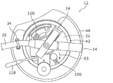
- FIG. 12A is a plan view showing the tone arm unit 12 according to Embodiment 1 in a state where each of the pair of lock supports 66a and 66b is located at the release position.
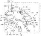
- FIG. 12B is an enlarged view of a part of the lock mechanism 18 according to Embodiment 1 in a state where each of the pair of lock supports 66a and 66b is located at the release position.
- 12C is a cross-sectional view taken along the line XII-XII of FIG. 9 in a state where each of the pair of lock supports 66a and 66b is located at the release position.
- FIG. 12A is a plan view showing the tone arm unit 12 according to Embodiment 1 in a state where each of the pair of lock supports 66a and 66b is located at the release position.
- FIG. 12B is an enlarged view of a part of the lock mechanism 18 according to Embodiment 1 in a state where each of the pair of lock supports 66a and 66b is located at
- FIG. 13A is a plan view showing the tone arm unit 12 according to Embodiment 1 in a state where each of the pair of lock supports 66a and 66b is located at the lock position.
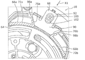
- FIG. 13B is an enlarged view showing a part of the lock mechanism 18 according to Embodiment 1 in a state where each of the pair of lock supports 66a and 66b is located at the lock position.
- 13C is a cross-sectional view taken along line XII-XII in FIG. 9 in a state where each of the pair of lock supports 66a and 66b is located at the lock position.
- the balance weight 32 is not shown in FIGS. 12A and 13A.
- each of the pair of lock supports 66a and 66b is located at the release position.
- the support main body portions 72a and 72b of the pair of lock supports 66a and 66b are separated from the ring rubber 64, the ring cam 40 can be rotated with respect to the cam base 36.
- the pair of inclined portions 98a and 98b of the push-in portion 90 push the inclined surfaces 76a and 76b of the support main body portions 72a and 72b of the pair of lock supports 66a and 66b, respectively.
- Each of the pair of lock supports 66a and 66b moves from the release position to the lock position.
- the cushion member 84 is compressed by being pressed by the support main body portions 72a and 72b of the pair of lock supports 66a and 66b.
- each of the support main body portions 72a and 72b of the pair of lock supports 66a and 66b is connected to the ring rubber 64. Touching. Accordingly, the rotation of the ring cam 40 relative to the cam base 36 is locked by the frictional force generated between the support main body portions 72a and 72b and the ring rubber 64. At this time, the ring rubber 64 is elastically deformed by being pressed (contacted) by the support main body portions 72a and 72b.
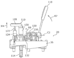
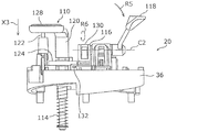
- FIG. 14A is a perspective view showing lifter mechanism 20 according to Embodiment 1 in a state where mounting table 128 is located at the upper limit position.
- FIG. 14B is a side view showing the lifter mechanism 20 according to Embodiment 1 in a state where the mounting table 128 is located at the upper limit position.
- FIG. 14C is a side view showing the tone arm unit 12 according to Embodiment 1 in a state where the mounting table 128 is located at the upper limit position.
- FIG. 14A is a perspective view showing lifter mechanism 20 according to Embodiment 1 in a state where mounting table 128 is located at the upper limit position.
- FIG. 14B is a side view showing the lifter mechanism 20 according to Embodiment 1 in a state where the mounting table 128 is located at the upper limit position.
- FIG. 14C is a side view showing the tone arm unit 12 according to Embodiment 1 in a state where the mounting table 128 is located at the upper limit position.
- FIG. 15A is a perspective view showing the lifter mechanism 20 according to Embodiment 1 in a state where the mounting table 128 is located at the lower limit position.
- FIG. 15B is a side view showing the lifter mechanism 20 according to Embodiment 1 in a state where the mounting table 128 is located at the lower limit position.
- FIG. 15C is a side view showing the tone arm unit 12 according to Embodiment 1 in a state where the mounting table 128 is located at the lower limit position.
- the arm base 22 and the arm member 26 are not shown in FIGS. 14A, 14B, 15A, and 15B.
- the lifter mechanism 20 is a mechanism for lowering the head shell 28 (the tip of the arm member 26) toward the record board 4 on the turntable 8. As shown in FIG. 14A, the lifter mechanism 20 includes a lift arm base 110, a gear damper 112, a coil spring 114 (an example of a second urging member), a cam member 116, and a lever member 118. Yes.
- the lift arm base 110 has a pair of support columns 120, 122, a plate member 124, a rack gear 126, and a mounting table 128.
- the pair of support columns 120 and 122 are supported by the cam base 36 so as to be movable up and down, and extend vertically upward from the upper surface of the cam base 36.
- the plate member 124 is attached to the support 120 and can be moved up and down together with the support 120.
- the rack gear 126 extends vertically downward from the plate member 124 and can be moved up and down together with the support 120.
- the mounting table 128 is a member for mounting the arm member 26, and is supported by the upper ends of the pair of support columns 120 and 122.
- the mounting table 128 can be moved up and down between an upper limit position (see FIGS. 14A to 14C) and a lower limit position (see FIGS. 15A to 15C) by moving the pair of support columns 120 and 122 up and down.
- an upper limit position see FIGS. 14A to 14C
- a lower limit position see FIGS. 15A to 15C
- the gear damper 112 is rotatably supported on the upper surface of the cam base 36.
- the gear damper 112 is meshed with the rack gear 126 of the lift arm base 110.
- the gear damper 112 applies a braking force (that is, a force against the lowering operation of the mounting table 128) to the mounting table 128 when the mounting table 128 is lowered from the upper limit position to the lower limit position.
- the coil spring 114 is disposed so as to cover the outer surface of the support column 120 below the cam base 36, and biases the mounting table 128 (support column 120) from the upper limit position toward the lower limit position. To do.
- the cam member 116 is rotatably supported on the upper surface of the cam base 36.
- the cam member 116 has a cam main body 130 and a support portion 132.
- the cam main body 130 rotates about a rotation axis C2 extending in a substantially horizontal direction.
- the support portion 132 is formed at a position eccentric from the rotation axis C ⁇ b> 2 of the cam main body portion 130.
- the lever member 118 is connected to the cam main body 130 of the cam member 116.
- the cam member 116 is moved between the first rotation position (see FIGS. 14A and 14B) and the second rotation position (see FIGS. 15A and 15B). Can be rotated.
- FIG. 14B when the cam member 116 is located at the first rotation position, the support portion 132 supports the plate member 124 from below. Thereby, the cam member 116 holds the mounting table 128 at the upper limit position.
- FIG. 15B when the cam member 116 is located at the second rotation position, the support portion 132 does not support the plate member 124 from below. As a result, the cam member 116 releases the holding of the mounting table 128 at the upper limit position.
- the cam member 116 is positioned at the first rotation position, and the mounting table 128 is held at the upper limit position.
- the user rotates the lever member 118 in the direction indicated by the arrow R5 in FIGS. 15A to 15C while the turntable 8 is rotating.
- the cam member 116 rotates from the first rotation position to the second rotation position in the direction indicated by the arrow R6 in FIGS. 15A and 15B.
- the mounting table 128 is lowered from the upper limit position toward the lower limit position in the direction indicated by the arrow X3 in FIGS. 15A to 15C with the arm member 26 being mounted by the biasing force of the coil spring 114.
- the mounting table 128 is gently lowered from the upper limit position toward the lower limit position while receiving the braking force from the gear damper 112, so that the record needle can be brought closer to the record board 4 gently. As a result, the reproduction of the record board 4 can be started smoothly.
- the user rotates the lever member 118 in the direction indicated by the arrow R7 in FIGS. 14A to 14C from the state shown in FIGS. 15A to 15C.
- the cam member 116 rotates from the second rotation position to the first rotation position in the direction indicated by the arrow R8 in FIGS. 14A and 14B.
- the mounting table 128 is pushed up by the support portion 132 of the cam member 116, and with the arm member 26 mounted, the mounting table 128 is directed from the lower limit position to the upper limit position in the direction indicated by the arrow X4 in FIGS. 14A to 14C. Rise. Thereby, the record needle can be separated from the record board 4.
- the tone arm unit 12 is used in the playback device 2 that plays back the record board 4.
- the tone arm unit 12 includes an arm member 26 for attaching the cartridge 30 to the tip portion, and an elevating mechanism 16 for elevating the arm member 26 with respect to the record board 4 along a predetermined axis.
- the elevating mechanism 16 is formed on a cam base 36 that supports the arm member 26, a ring cam 40 that is rotatable about a predetermined axis with respect to the cam base 36, and the cam base 36.
- a first guide portion 48 extending while inclining along, and a second guide portion 56 formed on the ring cam 40 and extending while inclining along the rotation direction so as to face the first guide portion 48.
- the cam base 36 moves up and down with respect to the ring cam 40 as the second guide portion 56 slides along the first guide portion 48.
- the elevating mechanism 16 can be easily incorporated into the tone arm unit 12 by arranging the cam base 36 and the ring cam 40 so that the first guide portion 48 and the second guide portion 56 face each other. it can. It should be noted that only the structure of the elevating mechanism 16 can be changed without greatly changing the appearance of a playback apparatus equipped with a conventional tone arm unit. As a result, the degree of satisfaction is high for users who prefer the classical appearance of conventional playback devices.
- the elevating mechanism 16 is further formed in the ring cam 40, formed in the groove portion 58 extending along the second guide portion 56, and the cam base 36, and is movably inserted into the groove portion 58.
- the projection 50 has a cam spacer 59 attached to the tip of the projection 50.
- the cam spacer 59 can suppress the protrusion 50 from coming out of the groove 58.
- the cam base 36 can be prevented from being unexpectedly detached from the ring cam 40.
- each of the first guide part 48 and the second guide part 56 is arranged in a plurality along the rotation direction.
- the tone arm unit 12 further includes a lock mechanism 18 for locking the rotation of the ring cam 40 relative to the cam base 36.
- the lock mechanism 18 includes a ring rubber 64 disposed on the outer surface of the ring cam 40, lock supports 66a and 66b movable between a lock position in contact with the ring rubber 64 and a release position away from the ring rubber 64.
- a lock shaft 70 is provided for moving the lock supports 66a and 66b between the lock position and the release position.
- the ring rubber 64 is formed of a rubber material and extends in a ring shape over the entire outer surface of the ring cam 40.
- the lock supports 66a and 66b can be reliably brought into contact with the ring rubber 64 regardless of the rotation position of the ring cam 40 with respect to the cam base 36.
- the tone arm unit 12 further includes a lifter mechanism 20 for lowering the tip of the arm member 26 toward the record board 4.
- the lifter mechanism 20 is a mounting table 128 on which the arm member 26 is placed, and an upper limit position where the distal end portion of the arm member 26 is separated from the record board 4, and a lower limit position where the distal end portion of the arm member 26 is brought closer to the record board 4.
- a gear damper 112 that applies a braking force to the mounting table 128 when the mounting table 128 is lowered from the upper limit position to the lower limit position.
- the mounting table 128 is gently lowered from the upper limit position toward the lower limit position while receiving the braking force by the gear damper 112, so that the tip of the arm member 26 can be brought closer to the record board 4 gently. As a result, the reproduction of the record board 4 can be started smoothly.
- the lifter mechanism 20 further includes a coil spring 114 that urges the mounting table 128 from the upper limit position toward the lower limit position, and a first rotation position that holds the mounting table 128 at the upper limit position.
- the cam member 116 that rotates between the second rotation position for releasing the holding of the mounting table 128 at the upper limit position, and the cam member 116 between the first rotation position and the second rotation position.
- a lever member 118 that rotates between them.
- the user can easily raise and lower the mounting table 128 between the upper limit position and the lower limit position by operating the lever member 118.
- the playback device 2 that plays back the record board 4 includes a turntable 8 on which the record board 4 is placed, a drive source 10 that rotates the turntable 8, and a turntable that rotates. 8 and any one of the above-described tone arm units 12 for picking up an audio signal from the record board 4 placed on the recording board 4.
- the elevating mechanism 16 can be easily incorporated into the tone arm unit 12 by arranging the cam base 36 and the ring cam 40 so that the first guide portion 48 and the second guide portion 56 face each other. it can. It should be noted that only the structure of the elevating mechanism 16 can be changed without greatly changing the appearance of a playback apparatus equipped with a conventional tone arm unit. As a result, the degree of satisfaction is high for users who prefer the classical appearance of conventional playback devices.
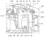
- FIG. 16 is a perspective view showing a lock mechanism 18A according to the second embodiment.
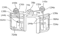
- FIG. 17 is a perspective view showing the lock mechanism 18A according to the second embodiment in a state where the pair of lock supports 66Aa, 66Ab, the lock plate 68, and the like are omitted.
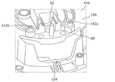
- FIG. 18 is a perspective view showing a part of the lock mechanism 18A according to the second embodiment.
- the jack base 62 and the like are not shown in FIGS. 16 and 17.
- the lock mechanism 18A includes a pair of spring members 134a and 134b (an example of a first biasing member) in addition to the components of the lock mechanism 18 according to the first embodiment. Yes.
- the spring member 134a is formed of a coiled torsion spring portion 136a and a wire spring portion 138a extending from the torsion spring portion 136a.
- the screw 140a is screwed into the screw hole 142a formed in the arm base mount 44A through the torsion spring portion 136a, whereby the torsion spring portion 136a is attached to the arm base mount 44A.
- the wire spring portion 138a is inserted through an opening 144a formed in the support main body portion 72Aa of the lock support 66Aa.
- the spring member 134b is formed symmetrically with the spring member 134a described above. That is, as shown in FIGS. 16 and 18, the spring member 134b is formed of a coiled torsion spring part 136b and a wire spring part 138b extending from the torsion spring part 136b. As shown in FIGS. 16 and 17, the screw 140b is screwed into the screw hole 142b formed in the arm base mount 44A through the torsion spring portion 136b, so that the torsion spring portion 136b is attached to the arm base mount 44A. . As shown in FIGS. 16 and 18, the wire spring portion 138b is inserted through an opening 144b formed in the support main body portion 72Ab of the lock support 66Ab.
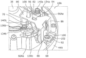
- FIG. 19 is a perspective view showing the lock mechanism 18A according to Embodiment 2 in a state where each of the pair of lock supports 66Aa and 66Ab is located at the release position.
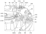
- FIG. 20 is a perspective view showing the lock mechanism 18A according to Embodiment 2 in a state where each of the pair of lock supports 66Aa and 66Ab is located at the lock position.
- the jack base 62 and the like are not shown in FIGS. 19 and 20.
- each of the pair of lock supports 66Aa and 66Ab is located at the release position. From this state, when the user rotates the lock shaft 70 in a predetermined direction with respect to the arm base mount 44A, as shown in FIG. 20, each of the pair of lock supports 66Aa and 66Ab is locked from the release position. Move to position. At this time, the wire spring portion 138a of the spring member 134a and the wire spring portion 138b of the spring member 134b are elastically deformed by being pressed by the pair of lock supports 66Aa and 66Ab, respectively. The torsion spring part 136a of the spring member 134a and the torsion spring part 136b of the spring member 134b are hardly elastically deformed.
- the lock mechanism 18A further includes spring members 134a and 134b that urge the lock supports 66Aa and 66Ab from the lock position toward the release position.
- the ring rubber 64 has adhesiveness. Even in such a case, the lock supports 66Aa and 66Ab can be easily separated from the ring rubber 64 by the biasing force of the spring members 134a and 134b.
- Embodiments 1 and 2 have been described as examples of the technology disclosed in the present application. However, the technology in the present disclosure is not limited to this, and can also be applied to an embodiment in which changes, replacements, additions, omissions, and the like are appropriately performed. Moreover, it is also possible to combine each component demonstrated in the said Embodiment 1 and 2 into a new embodiment.
- a gap is formed between the first guide portion 48 and the second guide portion 56, but the present invention is not limited to this, and the first guide portion 48 and the second guide portion 56 May be brought into contact with each other.
- This disclosure is applicable to a tone arm unit used in a playback device for playing a record board.
Landscapes
- Holding Or Fastening Of Disk On Rotational Shaft (AREA)
- Transmission Devices (AREA)
Abstract
トーンアームユニット(12)は、カートリッジ(30)を先端部に取り付けるためのアーム部材(26)と、アーム部材(26)をレコード盤(4)に対して軸線に沿って昇降させるための昇降機構(16)とを備える。昇降機構(16)は、アーム部材(26)を支持するカムベース(36)と、カムベース(36)に対して軸線を中心に回動可能に設けられたリングカム(40)と、カムベース(36)に形成され、リングカム(40)の回動方向に沿って傾斜しながら延びる第1のガイド部(48)と、リングカム(40)に形成され、第1のガイド部(48)に対向するように且つ回動方向に沿って傾斜しながら延びる第2のガイド部(56)とを有する。カムベース(36)は、リングカム(40)がカムベース(36)に対して回動した際に、第2のガイド部(56)が第1のガイド部(48)に沿ってスライドすることにより、リングカム(40)に対して昇降する。
Description
本開示は、トーンアームユニット及びこれを備えた再生装置に関する。
レコード盤(アナログディスク)を再生する再生装置が知られている。再生装置には、レコード盤から音声信号をピックアップするためのトーンアームユニットが搭載されている(例えば、特許文献1参照)。トーンアームユニットは、本体部材と、本体部材に配置されたベース部材と、ベース部材に支持されたアーム部材とを備えている。アーム部材の先端部には、レコード針を有するカートリッジが着脱可能に取り付けられている。
レコード盤から音声信号を精度良くピックアップするためには、レコード針がレコード盤の溝をトレースする際に、アーム部材の姿勢を略水平に保つ必要がある。そのため、従来のトーンアームユニットには、アーム部材の姿勢が略水平となるように、アーム部材のレコード盤からの高さ位置を調節するための昇降機構が搭載されている。
昇降機構は、ベース部材と本体部材との間に回動可能に配置された調節リングを有している。調節リングの内側面及びベース部材の外側面の各々には6条ネジが形成されており、これらの6条ネジは互いに噛み合わされている。調節リングをベース部材に対して回動させることにより、ベース部材が本体部材に対して昇降し、アーム部材のレコード盤からの高さ位置が調節される。
本開示は、昇降機構を容易に組み込むことができるトーンアームユニット及び再生装置を提供する。
本開示におけるトーンアームユニットは、レコード盤を再生する再生装置に用いられるトーンアームユニットであって、カートリッジを先端部に取り付けるためのアーム部材と、アーム部材をレコード盤に対して所定の軸線に沿って昇降させるための昇降機構と、を備え、昇降機構は、アーム部材を支持する支持部材と、支持部材に対して所定の軸線を中心に回動可能に設けられた回動部材と、支持部材に形成され、回動部材の回動方向に沿って傾斜しながら延びる第1のガイド部と、回動部材に形成され、第1のガイド部に対向するように且つ回動方向に沿って傾斜しながら延びる第2のガイド部と、を有し、支持部材は、回動部材が支持部材に対して回動した際に、第2のガイド部が第1のガイド部に沿ってスライドすることにより、回動部材に対して昇降する。
本開示におけるトーンアームユニットによれば、昇降機構を容易に組み込むことができる。
(本開示の基礎となった知見)
本発明者らは、「背景技術」の欄において記載した技術に関し、以下の問題が生じることを見出した。
本発明者らは、「背景技術」の欄において記載した技術に関し、以下の問題が生じることを見出した。
上述した従来のトーンアームユニットにおいて昇降機構を組み込む際には、まず、調節リングの内側面及びベース部材の外側面の各々に形成された6条ネジにグリスを塗布する。その後、調節リングの内側面に形成された6条ネジの6本のネジ山の端部と、ベース部材の外側面に形成された6条ネジの6本のネジ山の端部とをそれぞれ位置合わせしながら、各6条ネジを相互に噛み合わせる。しかしながら、このような構成では、昇降機構を組み込むための工数が増大するという問題が生じる。
以下、適宜図面を参照しながら、実施の形態を詳細に説明する。但し、必要以上に詳細な説明は省略する場合がある。例えば、既によく知られた事項の詳細説明や実質的に同一の構成に対する重複説明を省略する場合がある。これは、以下の説明が不必要に冗長になるのを避け、当業者の理解を容易にするためである。
なお、発明者らは、当業者が本開示を十分に理解するために添付図面及び以下の説明を提供するのであって、これらによって請求の範囲に記載の主題を限定することを意図するものではない。
(実施の形態1)
以下、図1~図15Cを参照しながら、実施の形態1について説明する。
以下、図1~図15Cを参照しながら、実施の形態1について説明する。
[1-1.再生装置の全体構成]
まず、図1を参照しながら、実施の形態1に係る再生装置2の全体構成について説明する。図1は、実施の形態1に係る再生装置2を示す斜視図である。
まず、図1を参照しながら、実施の形態1に係る再生装置2の全体構成について説明する。図1は、実施の形態1に係る再生装置2を示す斜視図である。
図1に示すように、再生装置2は、レコード盤4を再生するための装置(いわゆる、レコードプレーヤ)である。再生装置2は、筐体6と、ターンテーブル8と、駆動源10と、トーンアームユニット12とを備えている。
筐体6は、平面視で略矩形状の箱形状を有している。ターンテーブル8は、レコード盤4を載置するための円板状のテーブルであり、筐体6の上面に回動可能に支持されている。駆動源10は、ターンテーブル8を回動させるためのモータであり、筐体6の内部に配置されている。
トーンアームユニット12は、回動するターンテーブル8に載置されたレコード盤4から音声信号をピックアップするためのユニットであり、筐体6の上面においてターンテーブル8に隣接して配置されている。本実施の形態の再生装置2では、トーンアームユニット12の構成に特徴がある。以下、トーンアームユニット12の構成について詳細に説明する。
[1-2.トーンアームユニットの構成]
[1-2-1.トーンアームユニットの全体構成]
次に、図2~図4を参照しながら、実施の形態1に係るトーンアームユニット12の全体構成について説明する。図2は、実施の形態1に係るトーンアームユニット12を示す斜視図である。図3は、実施の形態1に係るトーンアームユニット12を示す分解斜視図である。図4は、図3とは異なる角度から見た状態での、実施の形態1に係るトーンアームユニット12を示す分解斜視図である。
[1-2-1.トーンアームユニットの全体構成]
次に、図2~図4を参照しながら、実施の形態1に係るトーンアームユニット12の全体構成について説明する。図2は、実施の形態1に係るトーンアームユニット12を示す斜視図である。図3は、実施の形態1に係るトーンアームユニット12を示す分解斜視図である。図4は、図3とは異なる角度から見た状態での、実施の形態1に係るトーンアームユニット12を示す分解斜視図である。
図2~図4に示すように、トーンアームユニット12は、トーンアーム部14と、昇降機構16と、ロック機構18と、リフター機構20とを備えている。以下、トーンアームユニット12の上記各構成要素について詳細に説明する。
[1-2-2.トーンアーム部]
まず、図2~図4を参照しながら、トーンアーム部14について説明する。
まず、図2~図4を参照しながら、トーンアーム部14について説明する。
図2~図4に示すように、トーンアーム部14は、アームベース22と、支持機構24と、アーム部材26とを有している。
アームベース22は、アーム部材26等を支持するための部材であり、平面視で円形状に形成されている。
支持機構24は、アーム部材26の基端部を水平方向及び垂直方向に揺動可能に支持するための機構であり、アームベース22の上面に配置されている。
アーム部材26は、水平面内で略S字状に屈曲しながら長尺状に延びている。アーム部材26の先端部には、ヘッドシェル28が支持されている。ヘッドシェル28には、レコード針を有するカートリッジ30(図1参照)が着脱可能に取り付けられている。また、アーム部材26の基端部には、ヘッドシェル28との重量バランスを取るためのバランスウェイト32が支持されている。
なお、レコード盤4を再生しない際には、ユーザは、アーム部材26をアームベース22の上面に配置されたフック状のアームレスト34に支持させる。レコード盤4を再生する際には、ユーザは、アーム部材26をアームレスト34から取り外した後に、アーム部材26を水平方向及び垂直方向に揺動させながら、載置台128(後述する)に載置させる。後述するように、載置台128がアーム部材26を載置した状態で下降することにより、ヘッドシェル28がターンテーブル8上のレコード盤4に近付き、カートリッジ30のレコード針がレコード盤4の溝をトレースする。
[1-2-3.昇降機構]
[1-2-3-1.昇降機構の構成]
次に、図3~図7Bを参照しながら、昇降機構16の構成について説明する。図5は、実施の形態1に係る昇降機構16を示す分解斜視図である。図6は、図5とは異なる角度から見た状態での、実施の形態1に係る昇降機構16を示す分解斜視図である。図7Aは、アーム部材26を最も下降させた状態での、図2のVII-VII線断面図である。図7Bは、図7Aの一部を拡大して示す断面斜視図である。
[1-2-3-1.昇降機構の構成]
次に、図3~図7Bを参照しながら、昇降機構16の構成について説明する。図5は、実施の形態1に係る昇降機構16を示す分解斜視図である。図6は、図5とは異なる角度から見た状態での、実施の形態1に係る昇降機構16を示す分解斜視図である。図7Aは、アーム部材26を最も下降させた状態での、図2のVII-VII線断面図である。図7Bは、図7Aの一部を拡大して示す断面斜視図である。
昇降機構16は、アーム部材26をターンテーブル8上のレコード盤4に対して昇降させるための機構である。図3及び図4に示すように、昇降機構16は、カムベース36(支持部材の一例)と、センターシャフト38と、リングカム40(回動部材の一例)と、操作リング42と、アームベースマウント44とを有している。
図5~図7Aに示すように、カムベース36は、円板状に形成されており、アームベース22の下面に複数のネジ46で固定されている。すなわち、カムベース36は、アームベース22を介してアーム部材26を支持している。
図5に示すように、カムベース36の下面における外周部には、複数(本実施の形態では3個)の第1のガイド部48が形成されている。複数の第1のガイド部48は、リングカム40の回動方向(すなわち、カムベース36の周方向)に沿って並んで配置されている。複数の第1のガイド部48の各々は、リングカム40の回動方向に沿って傾斜しながら延びている。すなわち、複数の第1のガイド部48の各々は、山部48aから谷部48bまで上り傾斜しながら円弧状に延びている。
さらに、図5に示すように、カムベース36の下面における外周部には、複数(本実施の形態では3個)の突部50が形成されている。複数の突部50は、カムベース36の下面から鉛直下方に延び、且つ、リングカム40の回動方向に沿って間隔を置いて配置されている。複数の突部50の各々の先端部には、抜け止め用ネジ52を捻じ込むためのネジ孔50aが形成されている。
センターシャフト38は、円柱状に形成され、カムベース36の下面における中央部から鉛直下方に延びている。センターシャフト38の中心軸線C1(所定の軸線の一例)は、鉛直方向に延び、後述するようにカムベース36がリングカム40に対して昇降する際の昇降軸線として機能する。さらに、センターシャフト38の中心軸線C1は、後述するようにリングカム40がカムベース36に対して回動する際の回動軸線としても機能する。なお、センターシャフト38は、例えば快削鋼又は真鍮等の金属で形成されている。
図5~図7Aに示すように、リングカム40は、有底円筒状に形成されており、カムベース36の外側面及び下面を覆う位置に配置されている。リングカム40の底部における中央部には、センターシャフト38を挿通するための円形状の孔54が形成されている。リングカム40は、センターシャフト38の中心軸線C1を中心にカムベース36に対して回動可能である。
図6に示すように、リングカム40の底部の上面における外周部には、複数(本実施の形態では3個)の第2のガイド部56が形成されている。複数の第2のガイド部56はそれぞれ、複数の第1のガイド部48に対応して、リングカム40の回動方向(すなわち、リングカム40の周方向)に沿って並んで配置されている。複数の第2のガイド部56の各々は、対応する第1のガイド部48に対向するように、且つ、リングカム40の回動方向に沿って傾斜しながら延びている。すなわち、複数の第2のガイド部56の各々は、谷部56bから山部56aまで上り傾斜しながら円弧状に延びている。図7A及び図7Bに示すように、複数の第2のガイド部56はそれぞれ、複数の第1のガイド部48に近接しており、第1のガイド部48と第2のガイド部56との間には例えば0.1mm程度の隙間が形成されている。
さらに、図5及び図6に示すように、リングカム40の底部における外周部には、複数(本実施の形態では3個)の溝部58が形成されている。複数の溝部58はそれぞれ、複数の第2のガイド部56に対応して、リングカム40の回動方向に沿って間隔を置いて配置されている。複数の溝部58の各々は、対応する第2のガイド部56に沿って円弧状に延びている。複数の溝部58にはそれぞれ、カムベース36の複数の突部50が移動可能に挿通されている。図5及び図7Bに示すように、複数の突部50の各々のネジ孔50aには、カムスペーサ59(抜け止め部材の一例)を介して抜け止め用ネジ52が捻じ込まれている。すなわち、カムスペーサ59は、抜け止め用ネジ52により突部50の先端部に取り付けられている。抜け止め用ネジ52及びカムスペーサ59は、溝部58を挟んでカムベース36と反対側に配置されている。カムスペーサ59の幅は、溝部58の幅よりも大きい。これらの複数のカムスペーサ59により、突部50が溝部58から抜ける(すなわち、カムベース36がリングカム40から外れる)のを抑制することができる。
図5~図7Aに示すように、操作リング42は、リングカム40の上端部における外側面に取り付けられている。ユーザは、操作リング42を手指で掴むことにより、リングカム40をカムベース36に対して回動させることができる。
図2~図4及び図7Aに示すように、アームベースマウント44は、有底円筒状に形成されており、リングカム40の外側面及び底部の下面を覆う位置に配置されている。アームベースマウント44の底部における中央部には、センターシャフト38を挿通するための円形状の孔60が形成されている。アームベースマウント44の底部の上面には、リングカム40が回動可能に支持されている。なお、アームベースマウント44は、例えばアルミダイキャスト等の金属で形成されている。
アームベースマウント44の下端部には、ジャックベース62が取り付けられている。ジャックベース62の内部には、ジャック端子が実装されたジャック基板(図示せず)等が配置されている。
[1-2-3-2.昇降機構の動作]
次に、図7A~図8Bを参照しながら、昇降機構16の動作について説明する。図8Aは、アーム部材26を最も上昇させた状態での、図2のVII-VII線断面図である。図8Bは、図8Aの一部を拡大して示す断面斜視図である。
次に、図7A~図8Bを参照しながら、昇降機構16の動作について説明する。図8Aは、アーム部材26を最も上昇させた状態での、図2のVII-VII線断面図である。図8Bは、図8Aの一部を拡大して示す断面斜視図である。
図7A及び図7Bに示す状態では、複数の第2のガイド部56の各々の山部56aは、対応する第1のガイド部48の谷部48bに対向している。この状態では、アーム部材26はターンテーブル8上のレコード盤4に対して最も下降しており、アーム部材26のアームベースマウント44の上端面からの高さH1は、最も低くなっている。
この状態から、ユーザがリングカム40をカムベース36に対して図7Bの矢印R1で示す方向に所定の角度(例えば、+120°)だけ回動させることにより、複数の第2のガイド部56がそれぞれ複数の第1のガイド部48に沿ってスライドする。このとき、複数の第2のガイド部56の各々の山部56aは、対応する第1のガイド部48の谷部48bから山部48aに向けて移動する。これにより、カムベース36は、複数の第2のガイド部56の各々の山部56aによって押し上げられることにより、リングカム40に対してセンターシャフト38の中心軸線C1に沿って上昇する。これに伴い、アーム部材26は、カムベース36及びアームベース22とともに、ターンテーブル8上のレコード盤4に対してセンターシャフト38の中心軸線C1に沿って上昇する。なお、リングカム40をカムベース36に対して回動させている間、カムベース36の突部50は、溝部58の一端部から他端部まで溝部58に沿って移動する。
図8A及び図8Bに示す状態では、複数の第2のガイド部56の各々の山部56aは、対応する第1のガイド部48の山部48aに対向している。この状態では、アーム部材26はターンテーブル8上のレコード盤4に対して最も上昇しており、アーム部材26のアームベースマウント44の上端面からの高さH2(>H1)は、最も高くなっている。なお、高さH2と高さH1との差(H2-H1)は、例えば約6mmである。
この状態から、リングカム40をカムベース36に対して図8Bの矢印R2で示す方向に所定の角度(例えば、-120°)だけ回動させることにより、複数の第2のガイド部56がそれぞれ複数の第1のガイド部48に沿ってスライドする。このとき、複数の第2のガイド部56の各々の山部56aは、対応する第1のガイド部48の山部48aから谷部48bに向けて移動する。これにより、カムベース36は、リングカム40に対してセンターシャフト38の中心軸線C1に沿って下降する。これに伴い、アーム部材26は、カムベース36及びアームベース22とともに、ターンテーブル8上のレコード盤4に対してセンターシャフト38の中心軸線C1に沿って下降する。なお、リングカム40をカムベース36に対して回動させている間、カムベース36の突部50は、溝部58の他端部から一端部まで溝部58に沿って移動する。
上述したようにアーム部材26をターンテーブル8上のレコード盤4に対して昇降させることにより、アーム部材26のレコード盤4からの高さ位置を調節することができる。これにより、レコード針がレコード盤4の溝をトレースする際に、アーム部材26の姿勢を略水平に保つことができ、レコード盤4から音声信号を精度良くピックアップすることができる。
[1-2-4.ロック機構]
[1-2-4-1.ロック機構の構成]
次に、図3~図5及び図9~図11を参照しながら、ロック機構18の構成について説明する。図9は、実施の形態1に係るロック機構18を示す斜視図である。図10は、ロックプレート68を省略した状態での、実施の形態1に係るロック機構18を示す斜視図である。図11は、実施の形態1に係るロック機構18の一部を抜き出して示す斜視図である。なお、説明の都合上、図9及び図10では、ジャックベース62等の図示を省略してある。
[1-2-4-1.ロック機構の構成]
次に、図3~図5及び図9~図11を参照しながら、ロック機構18の構成について説明する。図9は、実施の形態1に係るロック機構18を示す斜視図である。図10は、ロックプレート68を省略した状態での、実施の形態1に係るロック機構18を示す斜視図である。図11は、実施の形態1に係るロック機構18の一部を抜き出して示す斜視図である。なお、説明の都合上、図9及び図10では、ジャックベース62等の図示を省略してある。
ロック機構18は、リングカム40のカムベース36に対する回動をロック(規制)するための機構である。図3、図4及び図9に示すように、ロック機構18は、リングラバー64(弾性部材の一例)と、一対のロックサポート66a,66b(接触部材の一例)と、ロックプレート68と、ロックシャフト70(操作部材の一例)とを有している。
図3~図5に示すように、リングラバー64は、リングカム40の外側面に取り付けられ、リングカム40の外側面の全周に亘ってリング状に延びている。リングラバー64は、例えばゴム材料で形成されている。なお、本実施の形態では、リングラバー64をゴム材料で形成したが、これに限定されず、例えば樹脂材料等の種々の弾性材料で形成してもよい。
一対のロックサポート66a,66bは、アームベースマウント44に移動可能に取り付けられ、リングラバー64に接触することによりリングカム40のカムベース36に対する回動をロックするための部材である。なお、一対のロックサポート66a,66bは、例えば樹脂で形成されている。
図11に示すように、ロックサポート66aは、サポート本体部72aと、取付片74aとを有している。サポート本体部72aは、プレート状に形成され、リングカム40の外側面の周方向に沿って湾曲している。サポート本体部72aの一側辺には、傾斜面76aが形成されている。取付片74aは、サポート本体部72aの凹面側から延びている。取付片74aには、長孔78aが形成されている。
図11に示すように、ロックサポート68bは、上述したロックサポート68aと左右対称に形成されている。すなわち、ロックサポート68bは、サポート本体部72bと、取付片74bとを有している。サポート本体部72bは、プレート状に形成され、リングカム40の外側面の周方向に沿って湾曲している。サポート本体部72bの一側辺には、傾斜面76bが形成されている。取付片74bは、サポート本体部72bの凹面側から延びている。取付片74bには、長孔78bが形成されている。
図3、図4、図9及び図10に示すように、一対のロックサポート66a,66bは、アームベースマウント44の側壁部に形成された切り欠き部80に配置され、各々の取付片74a,74bが対向するように互いに隣接している。なお、リングラバー64の一部は、アームベースマウント44の切り欠き部80を通して、アームベースマウント44の外部に露出している。そのため、一対のロックサポート66a,66bの各々のサポート本体部72a,72bの凹面側は、リングラバー64の一部に対向している。
図10に示すように、一対のロックサポート66a,66bの各々の取付片74a,74bの長孔78a,78bには、アームベースマウント44の底部の下面に形成された突起82が移動可能に挿通されている。これにより、一対のロックサポート66a,66bの各々は、サポート本体部72a,72bがリングラバー64から離れる解除位置(後述する図12B及び図12C参照)と、サポート本体部72a,72bがリングラバー64に接触するロック位置(後述する図13B及び図13C参照)との間を移動可能である。なお、図10に示すように、一対のロックサポート66a,66bの各々のサポート本体部72a,72bとアームベースマウント44の切り欠き部80の周縁部との間には、弾力性を有するクッション部材84が介在されている。
ロックプレート68は、一対のロックサポート66a,66bの各々を解除位置からロック位置に向けて押し込むための部材である。なお、ロックプレート68は、例えば鉄等の金属で形成されている。図3、図4、図9及び図11に示すように、ロックプレート68は、水平部86と、垂直部88と、押込部90と、取付部92とを有している。
水平部86には、アームベースマウント44の突起82が移動可能に挿通される長孔94と、ロックシャフト70の偏心軸108(後述する)が回動可能に挿通される孔96とが形成されている。垂直部88は、水平部86の一端部から、水平部86に対して略垂直に延びている。押込部90は、垂直部88の一端部に形成され、垂直部88に対して略垂直に延びている。押込部90の両端部にはそれぞれ、一対の傾斜部98a,98bが形成されている。取付部92は、押込部90の中央部から、水平部86に対して略平行に延びている。取付部92には、ネジ100を挿通するための長孔102が形成されている。
図9に示すように、ネジ100が取付部92の長孔102を通してアームベースマウント44に形成されたネジ孔104(図10参照)に捻じ込まれることにより、ロックプレート68がアームベースマウント44に取り付けられている。このとき、ネジ100と長孔102との間には遊びが存在するため、ロックプレート68は、アームベースマウント44の径方向に沿って往復移動することができる。水平部86の長孔94には、アームベースマウント44の突起82が移動可能に挿通されている。また、後述する図12C及び図13Cに示すように、押込部90の一対の傾斜部98a,98bはそれぞれ、一対のロックサポート66a,66bの各々のサポート本体部72a,72bの傾斜面76a,76bに接触している。
ロックシャフト70は、一対のロックサポート66a,66bの各々を解除位置とロック位置との間で移動させるための部材である。図3及び図4に示すように、ロックシャフト70は、長尺状に形成され、アームベース22、カムベース36、リングカム40及びアームベースマウント44を貫通して配置されている。ロックシャフト70は、その中心軸線を中心にアームベースマウント44に対して回動可能である。
ロックシャフト70の上端部には、ロックノブ106が形成されている。後述する図12Aに示すように、ロックノブ106は、アームベース22の上面に配置されている。ユーザは、ロックノブ106を手指で摘むことにより、ロックシャフト70をアームベースマウント44に対して回動させることができる。ロックシャフト70の下端部には、ロックシャフト70の中心軸線に対して偏心した偏心軸108が形成されている。図9に示すように、偏心軸108は、ロックプレート68の水平部86の孔96に回動可能に挿通されている。
[1-2-4-2.ロック機構の動作]
次に、図12A~図13Cを参照しながら、ロック機構18の動作について説明する。図12Aは、一対のロックサポート66a,66bの各々が解除位置に位置している状態での、実施の形態1に係るトーンアームユニット12を示す平面図である。図12Bは、一対のロックサポート66a,66bの各々が解除位置に位置している状態での、実施の形態1に係るロック機構18の一部を拡大して示す図である。図12Cは、一対のロックサポート66a,66bの各々が解除位置に位置している状態での、図9のXII-XII線断面図である。図13Aは、一対のロックサポート66a,66bの各々がロック位置に位置している状態での、実施の形態1に係るトーンアームユニット12を示す平面図である。図13Bは、一対のロックサポート66a,66bの各々がロック位置に位置している状態での、実施の形態1に係るロック機構18の一部を拡大して示す図である。図13Cは、一対のロックサポート66a,66bの各々がロック位置に位置している状態での、図9のXII-XII線断面図である。なお、説明の都合上、図12A及び図13Aでは、バランスウェイト32の図示を省略してある。
次に、図12A~図13Cを参照しながら、ロック機構18の動作について説明する。図12Aは、一対のロックサポート66a,66bの各々が解除位置に位置している状態での、実施の形態1に係るトーンアームユニット12を示す平面図である。図12Bは、一対のロックサポート66a,66bの各々が解除位置に位置している状態での、実施の形態1に係るロック機構18の一部を拡大して示す図である。図12Cは、一対のロックサポート66a,66bの各々が解除位置に位置している状態での、図9のXII-XII線断面図である。図13Aは、一対のロックサポート66a,66bの各々がロック位置に位置している状態での、実施の形態1に係るトーンアームユニット12を示す平面図である。図13Bは、一対のロックサポート66a,66bの各々がロック位置に位置している状態での、実施の形態1に係るロック機構18の一部を拡大して示す図である。図13Cは、一対のロックサポート66a,66bの各々がロック位置に位置している状態での、図9のXII-XII線断面図である。なお、説明の都合上、図12A及び図13Aでは、バランスウェイト32の図示を省略してある。
図12A~図12Cに示す状態では、一対のロックサポート66a,66bの各々は解除位置に位置している。この状態では、一対のロックサポート66a,66bの各々のサポート本体部72a,72bがリングラバー64から離れているので、リングカム40をカムベース36に対して回動させることができる。
この状態から、リングカム40のカムベース36に対する回動をロックさせたい際には、ユーザは、ロックノブ106を手指で摘んで、ロックシャフト70をアームベースマウント44に対して図13Aの矢印R3で示す方向に回動させる。これにより、偏心軸108は、ロックシャフト70の中心軸線を中心に、図13Bの矢印R3で示す方向に回動する。このとき、偏心軸108がロックプレート68の水平部86の孔96の周縁部を押圧することにより、ロックプレート68は、図13Bの矢印X1で示すように、一対のロックサポート66a,66bに近付く方向に移動する。これにより、図13Cに示すように、押込部90の一対の傾斜部98a,98bはそれぞれ、一対のロックサポート66a,66bの各々のサポート本体部72a,72bの傾斜面76a,76bを押し込むことにより、一対のロックサポート66a,66bの各々は解除位置からロック位置に移動する。このとき、図13Bに示すように、クッション部材84は、一対のロックサポート66a,66bの各々のサポート本体部72a,72bにより押圧されることにより圧縮されている。
図13A~図13Cに示すように、一対のロックサポート66a,66bの各々がロック位置に位置している状態では、一対のロックサポート66a,66bの各々のサポート本体部72a,72bがリングラバー64に接触している。これにより、サポート本体部72a,72bとリングラバー64との間に生じる摩擦力によって、リングカム40のカムベース36に対する回動がロックされる。このとき、リングラバー64は、サポート本体部72a,72bによって押圧(接触)されることにより弾性変形する。
この状態から、リングカム40をカムベース36に対して回動させたい際には、ユーザは、ロックノブ106を手指で摘んで、ロックシャフト70をアームベースマウント44に対して図12Aの矢印R4で示す方向に回動させる。これにより、偏心軸108は、ロックシャフト70の中心軸線を中心に、図12Bの矢印R4で示す方向に回動する。このとき、偏心軸108がロックプレート68の水平部86の孔96の周縁部を押圧することにより、ロックプレート68は、図12Bの矢印X2で示すように、一対のロックサポート66a,66bから離れる方向に移動する。これにより、図12B及び図12Cに示すように、一対のロックサポート66a,66bの各々は、クッション部材84の反発力を受けて、ロック位置から解除位置に移動する。
[1-2-5.リフター機構]
[1-2-5-1.リフター機構の構成]
次に、図14A~図15Cを参照しながら、リフター機構20の構成について説明する。図14Aは、載置台128が上限位置に位置している状態での、実施の形態1に係るリフター機構20を示す斜視図である。図14Bは、載置台128が上限位置に位置している状態での、実施の形態1に係るリフター機構20を示す側面図である。図14Cは、載置台128が上限位置に位置している状態での、実施の形態1に係るトーンアームユニット12を示す側面図である。図15Aは、載置台128が下限位置に位置している状態での、実施の形態1に係るリフター機構20を示す斜視図である。図15Bは、載置台128が下限位置に位置している状態での、実施の形態1に係るリフター機構20を示す側面図である。図15Cは、載置台128が下限位置に位置している状態での、実施の形態1に係るトーンアームユニット12を示す側面図である。なお、説明の都合上、図14A、図14B、図15A及び図15Bでは、アームベース22及びアーム部材26等の図示を省略してある。
[1-2-5-1.リフター機構の構成]
次に、図14A~図15Cを参照しながら、リフター機構20の構成について説明する。図14Aは、載置台128が上限位置に位置している状態での、実施の形態1に係るリフター機構20を示す斜視図である。図14Bは、載置台128が上限位置に位置している状態での、実施の形態1に係るリフター機構20を示す側面図である。図14Cは、載置台128が上限位置に位置している状態での、実施の形態1に係るトーンアームユニット12を示す側面図である。図15Aは、載置台128が下限位置に位置している状態での、実施の形態1に係るリフター機構20を示す斜視図である。図15Bは、載置台128が下限位置に位置している状態での、実施の形態1に係るリフター機構20を示す側面図である。図15Cは、載置台128が下限位置に位置している状態での、実施の形態1に係るトーンアームユニット12を示す側面図である。なお、説明の都合上、図14A、図14B、図15A及び図15Bでは、アームベース22及びアーム部材26等の図示を省略してある。
リフター機構20は、ヘッドシェル28(アーム部材26の先端部)をターンテーブル8上のレコード盤4に向けて下降させるための機構である。図14Aに示すように、リフター機構20は、リフトアームベース110と、ギアダンパー112と、コイルバネ114(第2の付勢部材の一例)と、カム部材116と、レバー部材118とを有している。
図14A及び図14Bに示すように、リフトアームベース110は、一対の支柱部120,122と、プレート部材124と、ラックギア126と、載置台128とを有している。一対の支柱部120,122は、カムベース36に昇降可能に支持されており、カムベース36の上面から鉛直上方に延びている。プレート部材124は、支柱部120に取り付けられており、支柱部120とともに昇降可能である。ラックギア126は、プレート部材124から鉛直下方に延びており、支柱部120とともに昇降可能である。
載置台128は、アーム部材26を載置するための部材であり、一対の支柱部120,122の各上端部に支持されている。載置台128は、一対の支柱部120,122が昇降することにより、上限位置(図14A~図14C参照)と下限位置(図15A~図15C参照)との間を昇降可能である。載置台128が上限位置に位置している際には、ヘッドシェル28はターンテーブル8上のレコード盤4から離れている。載置台128が下限位置に位置している際には、ヘッドシェル28はターンテーブル8上のレコード盤4に近付き、レコード針はレコード盤4の溝に接触する。
図14Aに示すように、ギアダンパー112は、カムベース36の上面に回動可能に支持されている。ギアダンパー112は、リフトアームベース110のラックギア126と噛み合わされている。ギアダンパー112は、載置台128が上限位置から下限位置まで下降している際に、載置台128に制動力(すなわち、載置台128の下降動作に逆らう力)を作用させる。
図14Bに示すように、コイルバネ114は、カムベース36の下方において支柱部120の外側面を覆うように配置されており、載置台128(支柱部120)を上限位置から下限位置に向けて付勢する。
図14A及び図14Bに示すように、カム部材116は、カムベース36の上面に回動可能に支持されている。カム部材116は、カム本体部130と、支持部132とを有している。カム本体部130は、略水平方向に延びる回動軸線C2を中心に回動する。支持部132は、カム本体部130の回動軸線C2から偏心した位置に形成されている。
レバー部材118は、カム部材116のカム本体部130に連結されている。ユーザがレバー部材118を手で回動させることにより、カム部材116を第1の回動位置(図14A及び図14B参照)と第2の回動位置(図15A及び図15B参照)との間で回動させることができる。図14Bに示すように、カム部材116が第1の回動位置に位置している際には、支持部132は、プレート部材124を下方から支持する。これにより、カム部材116は、載置台128を上限位置に保持する。図15Bに示すように、カム部材116が第2の回動位置に位置している際には、支持部132は、プレート部材124を下方から支持しない。これにより、カム部材116は、載置台128の上限位置での保持を解除する。
[1-2-5-2.リフター機構の動作]
次に、図14A~図15Cを参照しながら、リフター機構20の動作について説明する。
次に、図14A~図15Cを参照しながら、リフター機構20の動作について説明する。
図14A~図14Cに示す状態では、カム部材116は第1の回動位置に位置しており、載置台128は上限位置に保持されている。例えばレコード盤4を再生する際には、ターンテーブル8が回動している状態で、ユーザは、レバー部材118を図15A~図15Cの矢印R5で示す方向に回動させる。これにより、カム部材116は、図15A及び図15Bの矢印R6で示す方向に、第1の回動位置から第2の回動位置まで回動する。その結果、載置台128は、コイルバネ114の付勢力により、アーム部材26を載置した状態で、図15A~図15Cの矢印X3で示す方向に上限位置から下限位置に向けて下降する。このとき、載置台128は、ギアダンパー112による制動力を受けながら、上限位置から下限位置に向けて緩やかに下降するので、レコード針をレコード盤4に緩やかに近付けることができる。その結果、レコード盤4の再生をスムーズに開始することができる。
例えばレコード盤4の再生が終了した際には、図15A~図15Cに示す状態から、ユーザは、レバー部材118を図14A~図14Cの矢印R7で示す方向に回動させる。これにより、カム部材116は、図14A及び図14Bの矢印R8で示す方向に、第2の回動位置から第1の回動位置まで回動する。その結果、載置台128は、カム部材116の支持部132によって押し上げられることにより、アーム部材26を載置した状態で、図14A~図14Cの矢印X4で示す方向に下限位置から上限位置に向けて上昇する。これにより、レコード針をレコード盤4から離すことができる。
[1-3.効果等]
上述したように、本実施の形態において、トーンアームユニット12は、レコード盤4を再生する再生装置2に用いられる。トーンアームユニット12は、カートリッジ30を先端部に取り付けるためのアーム部材26と、アーム部材26をレコード盤4に対して所定の軸線に沿って昇降させるための昇降機構16とを備える。昇降機構16は、アーム部材26を支持するカムベース36と、カムベース36に対して所定の軸線を中心に回動可能に設けられたリングカム40と、カムベース36に形成され、リングカム40の回動方向に沿って傾斜しながら延びる第1のガイド部48と、リングカム40に形成され、第1のガイド部48に対向するように且つ回動方向に沿って傾斜しながら延びる第2のガイド部56とを有する。カムベース36は、リングカム40がカムベース36に対して回動した際に、第2のガイド部56が第1のガイド部48に沿ってスライドすることにより、リングカム40に対して昇降する。
上述したように、本実施の形態において、トーンアームユニット12は、レコード盤4を再生する再生装置2に用いられる。トーンアームユニット12は、カートリッジ30を先端部に取り付けるためのアーム部材26と、アーム部材26をレコード盤4に対して所定の軸線に沿って昇降させるための昇降機構16とを備える。昇降機構16は、アーム部材26を支持するカムベース36と、カムベース36に対して所定の軸線を中心に回動可能に設けられたリングカム40と、カムベース36に形成され、リングカム40の回動方向に沿って傾斜しながら延びる第1のガイド部48と、リングカム40に形成され、第1のガイド部48に対向するように且つ回動方向に沿って傾斜しながら延びる第2のガイド部56とを有する。カムベース36は、リングカム40がカムベース36に対して回動した際に、第2のガイド部56が第1のガイド部48に沿ってスライドすることにより、リングカム40に対して昇降する。
これにより、第1のガイド部48と第2のガイド部56とが互いに対向するように、カムベース36とリングカム40とを配置することにより、昇降機構16をトーンアームユニット12に容易に組み込むことができる。なお、従来のトーンアームユニットを搭載した再生装置に対して、外観を大きく変えることなく、昇降機構16の構造のみを変えることができる。その結果、従来の再生装置のクラシカルな外観を好むユーザにとって満足度の高いものとなる。
また、本実施の形態において、昇降機構16は、さらに、リングカム40に形成され、第2のガイド部56に沿って延びる溝部58と、カムベース36に形成され、溝部58に移動可能に挿通された突部50と、突部50の先端部に取り付けられたカムスペーサ59とを有する。
これにより、カムスペーサ59によって、突部50が溝部58から抜けるのを抑制することができる。その結果、リングカム40をカムベース36に対して回動させた際に、カムベース36がリングカム40から不意に外れるのを抑制することができる。
また、本実施の形態において、第1のガイド部48及び第2のガイド部56の各々は、回動方向に沿って複数並んで配置されている。
これにより、リングカム40をカムベース36に対して回動させた際に、カムベース36をリングカム40に対して安定して昇降させることができる。
また、本実施の形態において、トーンアームユニット12は、さらに、リングカム40のカムベース36に対する回動をロックするためのロック機構18を備える。ロック機構18は、リングカム40の外側面に配置されたリングラバー64と、リングラバー64に接触するロック位置と、リングラバー64から離れる解除位置との間を移動可能なロックサポート66a,66bと、ロックサポート66a,66bをロック位置と解除位置との間で移動させるためのロックシャフト70とを有する。
これにより、ロックサポート66a,66bを解除位置からロック位置に移動させた際には、ロックサポート66a,66bがリングラバー64に接触することにより、リングラバー64が弾性変形する。その結果、ロックサポート66a,66b等の寸法バラツキがある場合であっても、リングラバー64の弾性変形量により上記の寸法バラツキを吸収することができるので、ロックサポート66a,66bをリングラバー64に確実に接触させることができる。
また、本実施の形態において、リングラバー64は、ゴム材料で形成され、リングカム40の外側面の全周に亘ってリング状に延びている。
これにより、リングカム40のカムベース36に対する回動位置に拘わらず、ロックサポート66a,66bをリングラバー64に確実に接触させることができる。
また、本実施の形態において、トーンアームユニット12は、さらに、アーム部材26の先端部をレコード盤4に向けて下降させるためのリフター機構20を備える。リフター機構20は、アーム部材26を載置する載置台128であって、アーム部材26の先端部をレコード盤4から離す上限位置と、アーム部材26の先端部をレコード盤4に近付ける下限位置との間を昇降可能な載置台128と、載置台128が上限位置から下限位置まで下降している際に、載置台128に制動力を作用させるギアダンパー112とを有する。
これにより、載置台128は、ギアダンパー112による制動力を受けながら、上限位置から下限位置に向けて緩やかに下降するので、アーム部材26の先端部をレコード盤4に緩やかに近付けることができる。その結果、レコード盤4の再生をスムーズに開始することができる。
また、本実施の形態において、リフター機構20は、さらに、載置台128を上限位置から下限位置に向けて付勢するコイルバネ114と、載置台128を上限位置に保持する第1の回動位置と、載置台128の上限位置での保持を解除する第2の回動位置との間を回動するカム部材116と、カム部材116を第1の回動位置と第2の回動位置との間で回動させるレバー部材118とを有する。
これにより、ユーザは、レバー部材118を操作することにより、載置台128を上限位置と下限位置との間で容易に昇降させることができる。
また、本実施の形態において、レコード盤4を再生する再生装置2は、レコード盤4を載置するためのターンテーブル8と、ターンテーブル8を回動させる駆動源10と、回動するターンテーブル8に載置されたレコード盤4から音声信号をピックアップする、上述したいずれかのトーンアームユニット12とを備える。
これにより、第1のガイド部48と第2のガイド部56とが互いに対向するように、カムベース36とリングカム40とを配置することにより、昇降機構16をトーンアームユニット12に容易に組み込むことができる。なお、従来のトーンアームユニットを搭載した再生装置に対して、外観を大きく変えることなく、昇降機構16の構造のみを変えることができる。その結果、従来の再生装置のクラシカルな外観を好むユーザにとって満足度の高いものとなる。
(実施の形態2)
次に、図16~図20を参照しながら、実施の形態2について説明する。なお、実施の形態2では、上記実施の形態1と同一の構成要素には同一の符号を付して、その説明を省略する。
次に、図16~図20を参照しながら、実施の形態2について説明する。なお、実施の形態2では、上記実施の形態1と同一の構成要素には同一の符号を付して、その説明を省略する。
[2-1.ロック機構の構成]
図16~図18を参照しながら、実施の形態2に係るトーンアームユニット12Aのロック機構18Aの構成について説明する。図16は、実施の形態2に係るロック機構18Aを示す斜視図である。図17は、一対のロックサポート66Aa,66Ab及びロックプレート68等を省略した状態での、実施の形態2に係るロック機構18Aを示す斜視図である。図18は、実施の形態2に係るロック機構18Aの一部を抜き出して示す斜視図である。なお、説明の都合上、図16及び図17では、ジャックベース62等の図示を省略してある。
図16~図18を参照しながら、実施の形態2に係るトーンアームユニット12Aのロック機構18Aの構成について説明する。図16は、実施の形態2に係るロック機構18Aを示す斜視図である。図17は、一対のロックサポート66Aa,66Ab及びロックプレート68等を省略した状態での、実施の形態2に係るロック機構18Aを示す斜視図である。図18は、実施の形態2に係るロック機構18Aの一部を抜き出して示す斜視図である。なお、説明の都合上、図16及び図17では、ジャックベース62等の図示を省略してある。
図16に示すように、ロック機構18Aは、上記実施の形態1に係るロック機構18の構成要素に加えて、一対のバネ部材134a,134b(第1の付勢部材の一例)を有している。
図16及び図18に示すように、バネ部材134aは、コイル状のねじりバネ部136aと、ねじりバネ部136aから延びる線バネ部138aとで形成されている。図16及び図17に示すように、ネジ140aがねじりバネ部136aを通してアームベースマウント44Aに形成されたネジ孔142aに捻じ込まれることにより、ねじりバネ部136aがアームベースマウント44Aに取り付けられている。図16及び図18に示すように、線バネ部138aは、ロックサポート66Aaのサポート本体部72Aaに形成された開口部144aに挿通されている。
バネ部材134bは、上述したバネ部材134aと左右対称に形成されている。すなわち、図16及び図18に示すように、バネ部材134bは、コイル状のねじりバネ部136bと、ねじりバネ部136bから延びる線バネ部138bとで形成されている。図16及び図17に示すように、ネジ140bがねじりバネ部136bを通してアームベースマウント44Aに形成されたネジ孔142bに捻じ込まれることにより、ねじりバネ部136bがアームベースマウント44Aに取り付けられている。図16及び図18に示すように、線バネ部138bは、ロックサポート66Abのサポート本体部72Abに形成された開口部144bに挿通されている。
[2-2.ロック機構の動作]
次に、図19及び図20を参照しながら、ロック機構18Aの動作について説明する。図19は、一対のロックサポート66Aa,66Abの各々が解除位置に位置している状態での、実施の形態2に係るロック機構18Aを示す斜視図である。図20は、一対のロックサポート66Aa,66Abの各々がロック位置に位置している状態での、実施の形態2に係るロック機構18Aを示す斜視図である。なお、説明の都合上、図19及び図20では、ジャックベース62等の図示を省略してある。
次に、図19及び図20を参照しながら、ロック機構18Aの動作について説明する。図19は、一対のロックサポート66Aa,66Abの各々が解除位置に位置している状態での、実施の形態2に係るロック機構18Aを示す斜視図である。図20は、一対のロックサポート66Aa,66Abの各々がロック位置に位置している状態での、実施の形態2に係るロック機構18Aを示す斜視図である。なお、説明の都合上、図19及び図20では、ジャックベース62等の図示を省略してある。
図19に示す状態では、一対のロックサポート66Aa,66Abの各々は解除位置に位置している。この状態から、ユーザがロックシャフト70をアームベースマウント44Aに対して所定の方向に回動させた際には、図20に示すように、一対のロックサポート66Aa,66Abの各々は解除位置からロック位置に移動する。このとき、バネ部材134aの線バネ部138a及びバネ部材134bの線バネ部138bはそれぞれ、一対のロックサポート66Aa,66Abによって押圧されることにより弾性変形する。なお、バネ部材134aのねじりバネ部136a及びバネ部材134bのねじりバネ部136bは、ほとんど弾性変形しない。
図20に示す状態から、ユーザがロックシャフト70をアームベースマウント44Aに対して上記所定の方向と反対方向に回動させた際には、図19に示すように、一対のロックサポート66Aa,66Abはそれぞれ、バネ部材134aの線バネ部138a及びバネ部材134bの線バネ部138bの弾性復元力を受けて、ロック位置から解除位置に移動する。
[2-3.効果等]
本実施の形態において、ロック機構18Aは、さらに、ロックサポート66Aa,66Abをロック位置から解除位置に向けて付勢するバネ部材134a,134bを有する
これにより、例えばリングラバー64が粘着性を有している場合であっても、バネ部材134a,134bの付勢力により、ロックサポート66Aa,66Abをリングラバー64から容易に離すことができる。
本実施の形態において、ロック機構18Aは、さらに、ロックサポート66Aa,66Abをロック位置から解除位置に向けて付勢するバネ部材134a,134bを有する
これにより、例えばリングラバー64が粘着性を有している場合であっても、バネ部材134a,134bの付勢力により、ロックサポート66Aa,66Abをリングラバー64から容易に離すことができる。
(他の実施の形態)
以上のように、本出願において開示する技術の例示として、実施の形態1及び2を説明した。しかしながら、本開示における技術は、これに限定されず、適宜、変更、置き換え、付加、省略などを行った実施の形態にも適用可能である。また、上記実施の形態1及び2で説明した各構成要素を組み合わせて、新たな実施の形態とすることも可能である。
以上のように、本出願において開示する技術の例示として、実施の形態1及び2を説明した。しかしながら、本開示における技術は、これに限定されず、適宜、変更、置き換え、付加、省略などを行った実施の形態にも適用可能である。また、上記実施の形態1及び2で説明した各構成要素を組み合わせて、新たな実施の形態とすることも可能である。
そこで、以下、他の実施の形態を例示する。
上記各実施の形態では、第1のガイド部48と第2のガイド部56との間に隙間を形成したが、これに限定されず、第1のガイド部48と第2のガイド部56とを互いに接触(密着)させてもよい。
以上のように、本開示における技術の例示として、実施の形態を説明した。そのために、添付図面及び詳細な説明を提供した。
したがって、添付図面及び詳細な説明に記載された構成要素の中には、課題解決のために必須な構成要素だけでなく、上記技術を例示するために、課題解決のためには必須でない構成要素も含まれ得る。そのため、それらの必須ではない構成要素が添付図面や詳細な説明に記載されていることをもって、直ちに、それらの必須ではない構成要素が必須であるとの認定をするべきではない。
また、上述の実施の形態は、本開示における技術を例示するためのものであるから、請求の範囲又はその均等の範囲において種々の変更、置き換え、付加、省略などを行うことができる。
本開示は、レコード盤を再生するための再生装置に用いられるトーンアームユニットに適用可能である。
2 再生装置
4 レコード盤
6 筐体
8 ターンテーブル
10 駆動源
12,12A トーンアームユニット
14 トーンアーム部
16 昇降機構
18,18A ロック機構
20 リフター機構
22 アームベース
24 支持機構
26 アーム部材
28 ヘッドシェル
30 カートリッジ
32 バランスウェイト
34 アームレスト
36 カムベース
38 センターシャフト
40 リングカム
42 操作リング
44,44A アームベースマウント
46,100,140a,140b ネジ
48 第1のガイド部
48a,56a 山部
48b,56b 谷部
50 突部
50a,104,142a,142b ネジ孔
52 抜け止め用ネジ
54,60,96 孔
56 第2のガイド部
58 溝部
59 カムスペーサ
62 ジャックベース
64 リングラバー
66a,66b,66Aa,66Ab ロックサポート
68 ロックプレート
70 ロックシャフト
72a,72b,72Aa,72Ab サポート本体部
74a,74b 取付片
76a,76b 傾斜面
78a,78b,94,102 長孔
80 切り欠き部
82 突起
84 クッション部材
86 水平部
88 垂直部
90 押込部
92 取付部
98a,98b 傾斜部
106 ロックノブ
108 偏心軸
110 リフトアームベース
112 ギアダンパー
114 付勢部材
116 カム部材
118 レバー部材
120,122 支柱部
124 プレート部材
126 ラックギア
128 載置台
130 カム本体部
132 支持部
134a,134b バネ部材
136a,136b ねじりバネ部
138a,138b 線バネ部
144a,144b 開口部
4 レコード盤
6 筐体
8 ターンテーブル
10 駆動源
12,12A トーンアームユニット
14 トーンアーム部
16 昇降機構
18,18A ロック機構
20 リフター機構
22 アームベース
24 支持機構
26 アーム部材
28 ヘッドシェル
30 カートリッジ
32 バランスウェイト
34 アームレスト
36 カムベース
38 センターシャフト
40 リングカム
42 操作リング
44,44A アームベースマウント
46,100,140a,140b ネジ
48 第1のガイド部
48a,56a 山部
48b,56b 谷部
50 突部
50a,104,142a,142b ネジ孔
52 抜け止め用ネジ
54,60,96 孔
56 第2のガイド部
58 溝部
59 カムスペーサ
62 ジャックベース
64 リングラバー
66a,66b,66Aa,66Ab ロックサポート
68 ロックプレート
70 ロックシャフト
72a,72b,72Aa,72Ab サポート本体部
74a,74b 取付片
76a,76b 傾斜面
78a,78b,94,102 長孔
80 切り欠き部
82 突起
84 クッション部材
86 水平部
88 垂直部
90 押込部
92 取付部
98a,98b 傾斜部
106 ロックノブ
108 偏心軸
110 リフトアームベース
112 ギアダンパー
114 付勢部材
116 カム部材
118 レバー部材
120,122 支柱部
124 プレート部材
126 ラックギア
128 載置台
130 カム本体部
132 支持部
134a,134b バネ部材
136a,136b ねじりバネ部
138a,138b 線バネ部
144a,144b 開口部
Claims (9)
- レコード盤を再生する再生装置に用いられるトーンアームユニットであって、
カートリッジを先端部に取り付けるためのアーム部材と、
前記アーム部材を前記レコード盤に対して所定の軸線に沿って昇降させるための昇降機構と、を備え、
前記昇降機構は、
前記アーム部材を支持する支持部材と、
前記支持部材に対して前記所定の軸線を中心に回動可能に設けられた回動部材と、
前記支持部材に形成され、前記回動部材の回動方向に沿って傾斜しながら延びる第1のガイド部と、
前記回動部材に形成され、前記第1のガイド部に対向するように且つ前記回動方向に沿って傾斜しながら延びる第2のガイド部と、を有し、
前記支持部材は、前記回動部材が前記支持部材に対して回動した際に、前記第2のガイド部が前記第1のガイド部に沿ってスライドすることにより、前記回動部材に対して昇降する
トーンアームユニット。 - 前記昇降機構は、さらに、
前記回動部材に形成され、前記第2のガイド部に沿って延びる溝部と、
前記支持部材に形成され、前記溝部に移動可能に挿通された突部と、
前記突部の先端部に取り付けられた抜け止め部材と、を有する
請求項1に記載のトーンアームユニット。 - 前記第1のガイド部及び前記第2のガイド部の各々は、前記回動方向に沿って複数並んで配置されている
請求項1又は2に記載のトーンアームユニット。 - 前記トーンアームユニットは、さらに、前記回動部材の前記支持部材に対する回動をロックするためのロック機構を備え、
前記ロック機構は、
前記回動部材の外側面に配置された弾性部材と、
前記弾性部材に接触するロック位置と、前記弾性部材から離れる解除位置との間を移動可能な接触部材と、
前記接触部材を前記ロック位置と前記解除位置との間で移動させるための操作部材と、を有する
請求項1~3のいずれか1項に記載のトーンアームユニット。 - 前記弾性部材は、ゴム材料で形成され、前記回動部材の前記外側面の全周に亘ってリング状に延びている
請求項4に記載のトーンアームユニット。 - 前記ロック機構は、さらに、前記接触部材を前記ロック位置から前記解除位置に向けて付勢する第1の付勢部材を有する
請求項4又は5に記載のトーンアームユニット。 - 前記トーンアームユニットは、さらに、前記アーム部材の前記先端部を前記レコード盤に向けて下降させるためのリフター機構を備え、
前記リフター機構は、
前記アーム部材を載置する載置台であって、前記アーム部材の前記先端部を前記レコード盤から離す上限位置と、前記アーム部材の前記先端部を前記レコード盤に近付ける下限位置との間を昇降可能な載置台と、
前記載置台が前記上限位置から前記下限位置まで下降している際に、前記載置台に制動力を作用させるギアダンパーと、を有する
請求項1~6のいずれか1項に記載のトーンアームユニット。 - 前記リフター機構は、さらに、
前記載置台を前記上限位置から前記下限位置に向けて付勢する第2の付勢部材と、
前記載置台を前記上限位置に保持する第1の回動位置と、前記載置台の前記上限位置での保持を解除する第2の回動位置との間を回動するカム部材と、
前記カム部材を前記第1の回動位置と前記第2の回動位置との間で回動させるレバー部材と、を有する
請求項7に記載のトーンアームユニット。 - レコード盤を再生する再生装置であって、
前記レコード盤を載置するためのターンテーブルと、
前記ターンテーブルを回動させる駆動源と、
回動する前記ターンテーブルに載置された前記レコード盤から音声信号をピックアップする、請求項1~8のいずれか1項に記載のトーンアームユニットと、を備える
再生装置。
Priority Applications (2)
| Application Number | Priority Date | Filing Date | Title |
|---|---|---|---|
| EP17889108.1A EP3564956B1 (en) | 2016-12-28 | 2017-10-23 | Tonearm unit and playback device |
| US16/348,088 US10789974B2 (en) | 2016-12-28 | 2017-10-23 | Tonearm unit and playback device |
Applications Claiming Priority (2)
| Application Number | Priority Date | Filing Date | Title |
|---|---|---|---|
| JP2016256002A JP6516164B2 (ja) | 2016-12-28 | 2016-12-28 | トーンアームユニット及び再生装置 |
| JP2016-256002 | 2016-12-28 |
Publications (1)
| Publication Number | Publication Date |
|---|---|
| WO2018123232A1 true WO2018123232A1 (ja) | 2018-07-05 |
Family
ID=62708173
Family Applications (1)
| Application Number | Title | Priority Date | Filing Date |
|---|---|---|---|
| PCT/JP2017/038117 Ceased WO2018123232A1 (ja) | 2016-12-28 | 2017-10-23 | トーンアームユニット及び再生装置 |
Country Status (4)
| Country | Link |
|---|---|
| US (1) | US10789974B2 (ja) |
| EP (1) | EP3564956B1 (ja) |
| JP (1) | JP6516164B2 (ja) |
| WO (1) | WO2018123232A1 (ja) |
Cited By (1)
| Publication number | Priority date | Publication date | Assignee | Title |
|---|---|---|---|---|
| WO2020137030A1 (ja) * | 2018-12-27 | 2020-07-02 | パナソニックIpマネジメント株式会社 | トーンアーム装置及び再生装置 |
Families Citing this family (1)
| Publication number | Priority date | Publication date | Assignee | Title |
|---|---|---|---|---|
| JP1625836S (ja) * | 2018-08-21 | 2019-03-04 |
Citations (4)
| Publication number | Priority date | Publication date | Assignee | Title |
|---|---|---|---|---|
| JPS5110904A (ja) * | 1974-07-16 | 1976-01-28 | Sony Corp | Pitsukuatsupuaamusochi |
| JPS5182402U (ja) * | 1974-12-24 | 1976-07-01 | ||
| JPS61296502A (ja) * | 1985-06-22 | 1986-12-27 | Audio Technica Corp | レコ−ドプレ−ヤ用ピツクアツプ |
| US6154435A (en) * | 1998-12-01 | 2000-11-28 | Ya Horng Electronic Co., Ltd. | Height adjusting device for a tone arm |
Family Cites Families (7)
| Publication number | Priority date | Publication date | Assignee | Title |
|---|---|---|---|---|
| US3307851A (en) * | 1963-08-20 | 1967-03-07 | Rca Corp | Automatic record changer |
| US3411791A (en) * | 1966-03-31 | 1968-11-19 | James T. Dennis | Automatic record changer |
| DE2164875A1 (ja) * | 1970-12-29 | 1972-08-31 | Pioneer Electronic Corp | |
| US3973777A (en) * | 1974-12-30 | 1976-08-10 | Avnet, Inc. | Cueing control |
| US5003522A (en) * | 1978-12-01 | 1991-03-26 | Dolby Ray Milton | Disc reproducing system for compensating mechanical imperfections |
| NL8402144A (nl) * | 1984-07-06 | 1986-02-03 | Philips Nv | Platenspeler met een liftinrichting voor de toonarm. |
| JPH06187601A (ja) | 1992-12-18 | 1994-07-08 | Teragaki Kenkyusho:Kk | トーンアーム |
-
2016
- 2016-12-28 JP JP2016256002A patent/JP6516164B2/ja active Active
-
2017
- 2017-10-23 WO PCT/JP2017/038117 patent/WO2018123232A1/ja not_active Ceased
- 2017-10-23 EP EP17889108.1A patent/EP3564956B1/en active Active
- 2017-10-23 US US16/348,088 patent/US10789974B2/en active Active
Patent Citations (4)
| Publication number | Priority date | Publication date | Assignee | Title |
|---|---|---|---|---|
| JPS5110904A (ja) * | 1974-07-16 | 1976-01-28 | Sony Corp | Pitsukuatsupuaamusochi |
| JPS5182402U (ja) * | 1974-12-24 | 1976-07-01 | ||
| JPS61296502A (ja) * | 1985-06-22 | 1986-12-27 | Audio Technica Corp | レコ−ドプレ−ヤ用ピツクアツプ |
| US6154435A (en) * | 1998-12-01 | 2000-11-28 | Ya Horng Electronic Co., Ltd. | Height adjusting device for a tone arm |
Non-Patent Citations (1)
| Title |
|---|
| See also references of EP3564956A4 * |
Cited By (4)
| Publication number | Priority date | Publication date | Assignee | Title |
|---|---|---|---|---|
| WO2020137030A1 (ja) * | 2018-12-27 | 2020-07-02 | パナソニックIpマネジメント株式会社 | トーンアーム装置及び再生装置 |
| JPWO2020137030A1 (ja) * | 2018-12-27 | 2021-09-09 | パナソニックIpマネジメント株式会社 | トーンアーム装置及び再生装置 |
| JP7054806B2 (ja) | 2018-12-27 | 2022-04-15 | パナソニックIpマネジメント株式会社 | トーンアーム装置及び再生装置 |
| US11335363B2 (en) * | 2018-12-27 | 2022-05-17 | Panasonic Intellectual Property Management Co., Ltd. | Tonearm device and reproduction device |
Also Published As
| Publication number | Publication date |
|---|---|
| EP3564956A1 (en) | 2019-11-06 |
| JP6516164B2 (ja) | 2019-05-22 |
| EP3564956A4 (en) | 2019-12-25 |
| US20200058321A1 (en) | 2020-02-20 |
| US10789974B2 (en) | 2020-09-29 |
| EP3564956B1 (en) | 2021-12-08 |
| JP2018106793A (ja) | 2018-07-05 |
Similar Documents
| Publication | Publication Date | Title |
|---|---|---|
| JP7054806B2 (ja) | トーンアーム装置及び再生装置 | |
| WO2018123232A1 (ja) | トーンアームユニット及び再生装置 | |
| KR860000656B1 (ko) | 기록원반 재생장치 | |
| JP3841659B2 (ja) | 光ディスクドライブ及び光ディスクドライブ用トレー | |
| US3821812A (en) | Device for moving magnetic head away from magnetic sheet in magnetic recording and reproducing apparatus of the spiral track type | |
| JPH0328753B2 (ja) | ||
| KR850001457B1 (ko) | 기록 원반 재생장치 | |
| JPH039172Y2 (ja) | ||
| JP2018106793A5 (ja) | ||
| JPS6235168Y2 (ja) | ||
| JPS5853746Y2 (ja) | シ−ト式録音再生装置のヘッド送り機構 | |
| KR100892378B1 (ko) | 디스크 플레이어의 트리거 장치 | |
| KR100272088B1 (ko) | 씨디플레이어의 클램퍼 지지구조 | |
| JPS6034145Y2 (ja) | 磁気シ−ト式録音再生装置の磁気ヘツド支持機構 | |
| JP3031949B2 (ja) | 円盤状記録媒体のチャッキング機構 | |
| JPS6037716Y2 (ja) | 記録再生装置 | |
| JPH0418107Y2 (ja) | ||
| JP2583108Y2 (ja) | マルチ式ディスクプレーヤ | |
| KR100425304B1 (ko) | 광디스크 체인저 | |
| JPH0348764Y2 (ja) | ||
| JP2007200376A (ja) | ディスクローディング装置 | |
| JPS5814370A (ja) | デイスク保持装置 | |
| JPS5958676A (ja) | 磁気デイスク装置 | |
| JP2001256705A (ja) | ディスクプレーヤ | |
| JPH0221071B2 (ja) |
Legal Events
| Date | Code | Title | Description |
|---|---|---|---|
| 121 | Ep: the epo has been informed by wipo that ep was designated in this application |
Ref document number: 17889108 Country of ref document: EP Kind code of ref document: A1 |
|
| NENP | Non-entry into the national phase |
Ref country code: DE |
|
| ENP | Entry into the national phase |
Ref document number: 2017889108 Country of ref document: EP Effective date: 20190729 |