WO2019116560A1 - Structure d'ouverture de tapis de plancher de véhicule - Google Patents
Structure d'ouverture de tapis de plancher de véhicule Download PDFInfo
- Publication number
- WO2019116560A1 WO2019116560A1 PCT/JP2017/045177 JP2017045177W WO2019116560A1 WO 2019116560 A1 WO2019116560 A1 WO 2019116560A1 JP 2017045177 W JP2017045177 W JP 2017045177W WO 2019116560 A1 WO2019116560 A1 WO 2019116560A1
- Authority
- WO
- WIPO (PCT)
- Prior art keywords
- floor carpet
- opening
- vehicle
- lid
- power supply
- Prior art date
- Legal status (The legal status is an assumption and is not a legal conclusion. Google has not performed a legal analysis and makes no representation as to the accuracy of the status listed.)
- Ceased
Links
Images

Classifications
-
- B—PERFORMING OPERATIONS; TRANSPORTING
- B60—VEHICLES IN GENERAL
- B60K—ARRANGEMENT OR MOUNTING OF PROPULSION UNITS OR OF TRANSMISSIONS IN VEHICLES; ARRANGEMENT OR MOUNTING OF PLURAL DIVERSE PRIME-MOVERS IN VEHICLES; AUXILIARY DRIVES FOR VEHICLES; INSTRUMENTATION OR DASHBOARDS FOR VEHICLES; ARRANGEMENTS IN CONNECTION WITH COOLING, AIR INTAKE, GAS EXHAUST OR FUEL SUPPLY OF PROPULSION UNITS IN VEHICLES
- B60K1/00—Arrangement or mounting of electrical propulsion units
- B60K1/04—Arrangement or mounting of electrical propulsion units of the electric storage means for propulsion
-
- B—PERFORMING OPERATIONS; TRANSPORTING
- B60—VEHICLES IN GENERAL
- B60N—SEATS SPECIALLY ADAPTED FOR VEHICLES; VEHICLE PASSENGER ACCOMMODATION NOT OTHERWISE PROVIDED FOR
- B60N3/00—Arrangements or adaptations of other passenger fittings, not otherwise provided for
- B60N3/04—Arrangements or adaptations of other passenger fittings, not otherwise provided for of floor mats or carpets
Definitions
- Patent Document 1 discloses a vehicle provided with a battery unit on a floor panel.
- the battery cover of the battery unit is provided with a plug access port for accessing the maintenance plug from the outside of the battery unit.
- the plug access port is covered by a removable access cover.
- An object of the present invention is to suppress the leakage of noise emitted from a power supply device into a vehicle compartment and to improve the quietness of the vehicle compartment.
- an opening and a lid portion capable of opening and closing the opening are formed in a portion covering the power supply device of the floor carpet laid to cover the power supply device. It is done.
- a cut is formed in the portion, and the cut defines at least a portion of the inner edge of the opening and at least a portion of the outer edge of the lid. The cut surface by the incision is inclined with respect to the thickness direction of the floor carpet near the incision.
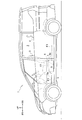
- FIG. 1 is a side view of a vehicle according to the embodiment.
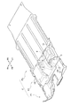
- FIG. 2 is a perspective view showing the structure of a floor carpet for a vehicle.
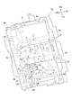
- FIG. 3 is a perspective view showing the configuration of the second floor carpet.
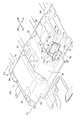
- FIG. 4 is a perspective view showing the opening formed in the bulging portion of the second floor carpet and the lid portion in the open position.
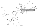
- FIG. 5 is a cross-sectional view taken along the line VV of FIG. 6 is a cross-sectional view taken along the line VI-VI in FIG.
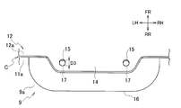
- FIG. 7 is a plan view of the tongue portion and the fixing piece in a state in which the lid portion is in the closed position and the clip is not inserted into the first and second through holes.
- the front of the vehicle is indicated as FR, the rear of the vehicle as RR, the right in the vehicle width direction as RH, the left in the vehicle width direction as LH, and the upper side of the vehicle as UP.
- a front seat 3 is disposed in a front seat in a cabin 2.
- the front seat 3 is composed of a right seat, which is a driver's seat, and a left seat, which is a front passenger seat, arranged in the vehicle width direction. Both sheets are configured to be slidable in the front-rear direction on the seat rails, respectively.
- a rear seat 4 is disposed in the rear of the front seat 3, behind the second seat and in the third row. The rear seat 4 in the third row is not shown.
- a power supply device 6 for driving the vehicle is disposed below the front seat 3 and above the floor panel 5.
- the power supply device 6 is a high voltage device having a battery unit 7 for storing power supplied to the electric motor, and a control device (inverter, DC / DC converter, etc.) for controlling the power of the battery unit 7 to a predetermined voltage.
- noise high frequency noise
- the battery unit 7 has a substantially rectangular parallelepiped shape having a longitudinal direction in the vehicle width direction, and extends in the vehicle width direction from under the right side seat to below the left side seat.
- a front cross member 8 a extends along the vehicle width direction on the front side of the battery unit 7, and a rear cross member 8 b extends along the vehicle width direction on the rear side of the battery unit 7. There is.
- the front part of the battery unit 7 is fastened to the front cross member 8a, and the rear part of the battery unit 7 is fastened to the rear cross member 8b.
- a floor carpet F is laid on the floor panel 5.
- the floor carpet F includes a surface material layer constituting a carpet surface, a backing material layer as a backing material, a buffer material layer made of felt or foam, and the like, and has sound insulation and sound absorption performance in a wide frequency range.
- the floor carpet F is given a shape according to the uneven shape of the floor panel 5 and the power supply device 6 by press molding.
- the floor carpet F is composed of a first floor carpet F1, a second floor carpet F2, and a third floor carpet F3.
- the first floor carpet F1 is laid on the floor panel 5 in front of the power supply 6, the second floor carpet F2 is laid to cover the power supply 6 from above, and the third floor carpet F3 is laid on the power supply 6 It is laid on the rear floor panel 5.
- the second floor carpet F2 has a bulging portion 9 that accommodates the power supply device 6 so as to cover it.
- the bulging portion 9 has a shape in which a substantially rectangular area bulges upward in a plan view, and the top wall 9a, the front wall 9b, the back wall 9c, the left wall 9d, and the right And a wall 9e.
- a recessed groove 9f extending in the front-rear direction is formed at a position corresponding to the two seat rails on the center side in the vehicle width direction.
- the front wall 9b extends below the front edge of the top wall 9a
- the back wall 9c extends below the rear edge of the top wall 9a.
- the bulging portion 9 is provided with a concavo-convex shape corresponding to the shape of the power supply device 6, and a large number of convex bending portions p and concave bending portions v are formed.
- the convex bending portion p the second floor carpet F2 is locally bent with a curvature larger than that of the surrounding wall (including the flat wall) so as to be convex toward the vehicle interior, and the concave bending portion In v, it is bent so as to be concave toward the vehicle interior.
- the convex bending portion p forms a ridge line r extending linearly or curvilinearly along the surface of the bulging portion 9 on the vehicle interior side.
- a convex bending portion p is formed at a portion where the front wall portion 9b and the left wall portion 9d intersect.
- the ridge line r is substantially linear, and is inclined so as to be positioned forward as it goes downward.
- a convex bending portion p is formed at the intersection of the front wall portion 9b and the top wall portion 9a, and the ridge line r extends substantially linearly along the vehicle width direction.
- the convex bending part p is formed in the part which the front wall part 9b and the left side wall of the concave groove 9f of the left side cross
- the ridge line r is substantially linear, and is inclined so as to be positioned forward as it goes downward.
- a substantially C-shaped cut C opened downward as viewed from the vehicle interior side is inserted in the left front portion of the bulging portion 9.
- the incision C penetrates from the surface on the vehicle interior side of the bulging portion 9 to the back surface on the side opposite to the vehicle interior, and the opening C and the lid 12 are formed by the incision C.
- the opening 11 has a substantially rectangular shape, and in the inner edge of the opening 11, both ends of the upper side 11 a and the two left and right sides 11 b and 11 c are notches C Is defined by Further, the lid 12 has a substantially rectangular shape corresponding to the opening 11, and the upper side 12a and the two left and right sides 12b and 12c of the outer edge of the lid 12 are defined by the notch C. ing.
- the lid portion 12 is connected to the lower side 11d of the inner edge portion of the opening 11 at the lower side 12d of the outer edge portion, and is integrated with the second floor carpet F2.
- the inner edge of the opening 11 is a surface 11A on the vehicle interior side, a back surface 11B on the opposite side of the vehicle interior, an edge of the surface 11A and an edge of the back surface 11B And a side surface 11C connecting the Further, the outer edge portion of the lid portion 12 has a surface 12A on the vehicle interior side, a back surface 12B on the side opposite to the vehicle interior, and a side surface 12C connecting an edge of the surface 12A and an edge of the back surface 12B. .
- the side surface 11C of the inner edge portion and the side surface 12C of the outer edge portion are cut surfaces by the incision C.
- the side surfaces 11C and 12C are substantially parallel to each other, and are inclined with respect to the thickness direction T of the floor carpet F near the incision C. Therefore, when the incision C is viewed from the vehicle interior along the thickness direction T, the edge of the back surface 11B of the opening 11 is located closer to the center of the opening 11 than the edge of the surface 12A of the lid 12 . That is, when the lid 12 is in the closed position, the accommodation space S below the second floor carpet F2 is blocked by the surface 12A of the lid 12 and is difficult to see.
- the lid 12 has a flat plate-like main body 13 cut out from the front wall 9 b of the bulging part 9 and a flat plate-like tongue piece cut out from the top wall 9 a of the bulging part 9. And fourteen.
- the tongue portion 14 is bent so as to be convex toward the vehicle interior from the upper portion of the main body portion 13 and extends rearward.
- the tongue piece 14 is provided with two first through holes 15.
- the fixing piece 16 is provided with two second through holes 17.
- the fixed piece 16 is fastened to the tongue piece 14 by a clip 18 made of, for example, resin, which is a fastener that is inserted into both the through holes 15 and 17.
- the cut surfaces 11C and 12C by the cut C at the inner edge of the opening 11 and the outer edge of the lid 12 are in the thickness direction T of the second floor carpet F2 near the cut C. It is inclined against. Therefore, the width W of the cut surfaces 11C and 12C is larger than when the cut surfaces 11C and 12C are parallel to the thickness direction T, and the depth of the gap formed between the cut surfaces 11C and 12C is increased. As a result, leakage of noise generated by the power supply device 6 into the vehicle compartment is suppressed.
- the incision C is viewed in the thickness direction T of the floor carpet F, the accommodation space S below the second floor carpet F2 is difficult to see, so the appearance of the opening of the second floor carpet F2 is improved.
- the second floor carpet F2 (floor carpet F) has sound absorbing performance.
- the area of cut surface 11C, 12C is larger than the case where they are parallel to thickness direction T. For this reason, when the noise generated by the power supply device 6 passes from the accommodation space S side to the vehicle interior side from the accommodation space S side, the noise generated in the power supply device 6 flows from the cut surfaces 11C, 12C into the second floor carpet F2. It is easy to be absorbed by Thereby, it is possible to suppress the leakage of the noise generated by the power supply device 6 into the vehicle compartment.
- the tongue pieces 14 are offset in the extending direction. Therefore, the main body 13 can be drawn in the extension direction of the tongue piece 14 by inserting the clip 18 into both the through holes 15 and 17 and fastening the tongue piece 14 to the fixing piece 16. Thereby, the width of the gap formed between the inner edge of the opening 11 and the outer edge of the lid 12 can be further reduced, and the sound insulation of the opening of the second floor carpet F2 can be further improved.
- the pull-in force generated when fastening the tongue piece portion 14 to the fixing piece 16 is It can be made to act on the direction toward the opposite side of the vehicle cabin (inside of the accommodation space S) with respect to 13.
- the outer edge of the lid 12 can be drawn toward the inner edge of the opening 11 with a greater force, and the width of the gap formed between them can be further reduced to open the second floor carpet F2.
- the sound insulation of the part can be further improved.
- the lid 12 is connected to the lower side 11d of the opening 11 at the lower side 12d of the outer edge and is integral with the second floor carpet F2, the lid 12 can be integrally formed with the second floor carpet F2. The appearance of the opening of the second floor carpet F2 is improved.
- the incision C is formed along the ridge line r of the convex bending portion p, and a part of the convex bending portion p constitutes a part of the lid portion 12, a rib shape is formed on the peripheral portion of the lid portion 12 Is given to improve the rigidity of the lid 12.
- the outer edge of the lid 12 and a part of the inner edge of the opening 11 are defined by the incision C, the entire periphery of the outer edge and the inner edge is defined by the incision C.
- the portion 12 may be configured to be removable from the opening 11.
- the shape of the incision C when viewed from the vehicle interior side is not particularly limited, and may be a C-shape, a U-shape, an L-shape, a circle, an ellipse, a polygon or the like.
- the position at which the outer edge of the lid 12 and the inner edge of the opening 11 are integrally connected is not particularly limited.
- the right side 12 c of the outer edge of the lid 12 and the right side 11 c of the inner edge of the opening 11 are connected You may
- the said opening part structure can be utilized for the floor carpet installed so that the said power supply device might be covered in the vehicle which mounted the power supply device on the floor panel.
Landscapes
- Engineering & Computer Science (AREA)
- Transportation (AREA)
- Mechanical Engineering (AREA)
- Chemical & Material Sciences (AREA)
- Combustion & Propulsion (AREA)
- Passenger Equipment (AREA)
- Arrangement Or Mounting Of Propulsion Units For Vehicles (AREA)
Abstract
L'invention concerne une structure d'ouverture de tapis de plancher de véhicule dans laquelle la partie d'un tapis de plancher (F2) recouvrant une alimentation électrique (6) est formée avec une ouverture (11) et un capot (12) capable d'ouvrir et de fermer l'ouverture (11). Au moins une partie du bord intérieur de l'ouverture (11) est définie par une découpe (C) formée dans ladite partie. Au moins une partie du bord extérieur du capot (12) est définie par la découpe (C). Les faces de coupe (11C, 12C) formées par la découpe (C) sont inclinées par rapport à la direction d'épaisseur (T) du tapis de plancher (F2) autour de la découpe (C).
Priority Applications (2)
| Application Number | Priority Date | Filing Date | Title |
|---|---|---|---|
| PCT/JP2017/045177 WO2019116560A1 (fr) | 2017-12-15 | 2017-12-15 | Structure d'ouverture de tapis de plancher de véhicule |
| JP2019558850A JP6935820B2 (ja) | 2017-12-15 | 2017-12-15 | 車両用フロアカーペットの開口部構造 |
Applications Claiming Priority (1)
| Application Number | Priority Date | Filing Date | Title |
|---|---|---|---|
| PCT/JP2017/045177 WO2019116560A1 (fr) | 2017-12-15 | 2017-12-15 | Structure d'ouverture de tapis de plancher de véhicule |
Publications (1)
| Publication Number | Publication Date |
|---|---|
| WO2019116560A1 true WO2019116560A1 (fr) | 2019-06-20 |
Family
ID=66820147
Family Applications (1)
| Application Number | Title | Priority Date | Filing Date |
|---|---|---|---|
| PCT/JP2017/045177 Ceased WO2019116560A1 (fr) | 2017-12-15 | 2017-12-15 | Structure d'ouverture de tapis de plancher de véhicule |
Country Status (2)
| Country | Link |
|---|---|
| JP (1) | JP6935820B2 (fr) |
| WO (1) | WO2019116560A1 (fr) |
Cited By (7)
| Publication number | Priority date | Publication date | Assignee | Title |
|---|---|---|---|---|
| US11397893B2 (en) | 2019-09-04 | 2022-07-26 | Google Llc | Neural network formation configuration feedback for wireless communications |
| US11663472B2 (en) | 2020-06-29 | 2023-05-30 | Google Llc | Deep neural network processing for a user equipment-coordination set |
| US11689940B2 (en) | 2019-12-13 | 2023-06-27 | Google Llc | Machine-learning architectures for simultaneous connection to multiple carriers |
| US11886991B2 (en) | 2019-11-27 | 2024-01-30 | Google Llc | Machine-learning architectures for broadcast and multicast communications |
| US11928587B2 (en) | 2019-08-14 | 2024-03-12 | Google Llc | Base station-user equipment messaging regarding deep neural networks |
| US12001943B2 (en) | 2019-08-14 | 2024-06-04 | Google Llc | Communicating a neural network formation configuration |
| DE102023120710B3 (de) | 2023-08-04 | 2025-01-30 | Dr. Ing. H.C. F. Porsche Aktiengesellschaft | Bodenbelag eines Kraftfahrzeugs |
Citations (10)
| Publication number | Priority date | Publication date | Assignee | Title |
|---|---|---|---|---|
| JPS6344263Y2 (fr) * | 1982-07-06 | 1988-11-17 | ||
| JPH0742712U (ja) * | 1993-12-31 | 1995-08-11 | 株式会社ホンダアクセス | 収納部付マット |
| JP2000108752A (ja) * | 1998-10-02 | 2000-04-18 | Takehiro:Kk | 車両用ラッゲージマット |
| JP2002166728A (ja) * | 2000-11-30 | 2002-06-11 | Toyota Auto Body Co Ltd | 高電圧バッテリの冷却構造 |
| WO2008134911A2 (fr) * | 2007-05-08 | 2008-11-13 | Rieter Technologies Ag | Dispositif de tapis de sol pour automobile et tapis d'insertion |
| US20080292827A1 (en) * | 2007-05-23 | 2008-11-27 | Jae Yong Lee | Car mat module |
| JP2009078577A (ja) * | 2007-09-25 | 2009-04-16 | Honda Motor Co Ltd | 車両用板体の成形方法及び車両用板体 |
| JP2013103690A (ja) * | 2011-11-16 | 2013-05-30 | Toyota Motor Corp | 車両の電池支持構造 |
| JP2016055823A (ja) * | 2014-09-11 | 2016-04-21 | トヨタ紡織株式会社 | 車両のフロア構造 |
| JP2016107986A (ja) * | 2014-12-07 | 2016-06-20 | 譲 伊藤 | 折畳み可能な荷物保持部を有するフロアボード |
Family Cites Families (1)
| Publication number | Priority date | Publication date | Assignee | Title |
|---|---|---|---|---|
| JP6244391B2 (ja) * | 2016-03-17 | 2017-12-06 | 本田技研工業株式会社 | 車両 |
-
2017
- 2017-12-15 JP JP2019558850A patent/JP6935820B2/ja active Active
- 2017-12-15 WO PCT/JP2017/045177 patent/WO2019116560A1/fr not_active Ceased
Patent Citations (10)
| Publication number | Priority date | Publication date | Assignee | Title |
|---|---|---|---|---|
| JPS6344263Y2 (fr) * | 1982-07-06 | 1988-11-17 | ||
| JPH0742712U (ja) * | 1993-12-31 | 1995-08-11 | 株式会社ホンダアクセス | 収納部付マット |
| JP2000108752A (ja) * | 1998-10-02 | 2000-04-18 | Takehiro:Kk | 車両用ラッゲージマット |
| JP2002166728A (ja) * | 2000-11-30 | 2002-06-11 | Toyota Auto Body Co Ltd | 高電圧バッテリの冷却構造 |
| WO2008134911A2 (fr) * | 2007-05-08 | 2008-11-13 | Rieter Technologies Ag | Dispositif de tapis de sol pour automobile et tapis d'insertion |
| US20080292827A1 (en) * | 2007-05-23 | 2008-11-27 | Jae Yong Lee | Car mat module |
| JP2009078577A (ja) * | 2007-09-25 | 2009-04-16 | Honda Motor Co Ltd | 車両用板体の成形方法及び車両用板体 |
| JP2013103690A (ja) * | 2011-11-16 | 2013-05-30 | Toyota Motor Corp | 車両の電池支持構造 |
| JP2016055823A (ja) * | 2014-09-11 | 2016-04-21 | トヨタ紡織株式会社 | 車両のフロア構造 |
| JP2016107986A (ja) * | 2014-12-07 | 2016-06-20 | 譲 伊藤 | 折畳み可能な荷物保持部を有するフロアボード |
Cited By (8)
| Publication number | Priority date | Publication date | Assignee | Title |
|---|---|---|---|---|
| US11928587B2 (en) | 2019-08-14 | 2024-03-12 | Google Llc | Base station-user equipment messaging regarding deep neural networks |
| US12001943B2 (en) | 2019-08-14 | 2024-06-04 | Google Llc | Communicating a neural network formation configuration |
| US11397893B2 (en) | 2019-09-04 | 2022-07-26 | Google Llc | Neural network formation configuration feedback for wireless communications |
| US11886991B2 (en) | 2019-11-27 | 2024-01-30 | Google Llc | Machine-learning architectures for broadcast and multicast communications |
| US12236347B2 (en) | 2019-11-27 | 2025-02-25 | Google Llc | Machine-learning architectures for broadcast and multicast communications |
| US11689940B2 (en) | 2019-12-13 | 2023-06-27 | Google Llc | Machine-learning architectures for simultaneous connection to multiple carriers |
| US11663472B2 (en) | 2020-06-29 | 2023-05-30 | Google Llc | Deep neural network processing for a user equipment-coordination set |
| DE102023120710B3 (de) | 2023-08-04 | 2025-01-30 | Dr. Ing. H.C. F. Porsche Aktiengesellschaft | Bodenbelag eines Kraftfahrzeugs |
Also Published As
| Publication number | Publication date |
|---|---|
| JP6935820B2 (ja) | 2021-09-15 |
| JPWO2019116560A1 (ja) | 2020-12-17 |
Similar Documents
| Publication | Publication Date | Title |
|---|---|---|
| WO2019116560A1 (fr) | Structure d'ouverture de tapis de plancher de véhicule | |
| JP5831752B2 (ja) | プルハンドルボックスの支持構造 | |
| JP5165491B2 (ja) | リヤコンソール | |
| US9505356B2 (en) | Vehicular interior part | |
| JP2009166599A (ja) | コンソールボックス | |
| JP5771904B2 (ja) | フロントピラートリムの取り付け構造 | |
| CN109552203B (zh) | 包括吸音构件的车辆内饰部件 | |
| JP2014193653A (ja) | カウルサイドトリムの取付構造 | |
| JP6114733B2 (ja) | 車両用収納ボックス構造 | |
| JP7068975B2 (ja) | 車両の収納部構造 | |
| JP5224123B2 (ja) | 物品収納ボックス及び物品収納ボックスの取り付け構造 | |
| JP5149726B2 (ja) | ピラートリムの取付構造 | |
| JP6064848B2 (ja) | 自動車の内装構造 | |
| JP6182089B2 (ja) | インストルメントパネル構造 | |
| JP2011083111A (ja) | 車両の充電器配置構造 | |
| JP6803318B2 (ja) | カウルトップガーニッシュ | |
| JP6281536B2 (ja) | 車両の防音構造 | |
| JP2018118695A (ja) | 自動車の遮音構造 | |
| JP5621578B2 (ja) | ウエスト部補強構造 | |
| JP6372735B2 (ja) | 自動車用ドアのドアトリム構造 | |
| JP5647422B2 (ja) | トリム | |
| JP6876742B2 (ja) | 車両用バッテリのエア吸気構造 | |
| JP2018176762A (ja) | 車両の防音構造 | |
| JP5946091B2 (ja) | 遮音カバーの取付け構造 | |
| US20080100081A1 (en) | Vehicle interior storage compartment |
Legal Events
| Date | Code | Title | Description |
|---|---|---|---|
| 121 | Ep: the epo has been informed by wipo that ep was designated in this application |
Ref document number: 17934817 Country of ref document: EP Kind code of ref document: A1 |
|
| ENP | Entry into the national phase |
Ref document number: 2019558850 Country of ref document: JP Kind code of ref document: A |
|
| NENP | Non-entry into the national phase |
Ref country code: DE |
|
| 122 | Ep: pct application non-entry in european phase |
Ref document number: 17934817 Country of ref document: EP Kind code of ref document: A1 |