WO2019131721A1 - 作業機及び作業機の製造方法 - Google Patents
作業機及び作業機の製造方法 Download PDFInfo
- Publication number
- WO2019131721A1 WO2019131721A1 PCT/JP2018/047751 JP2018047751W WO2019131721A1 WO 2019131721 A1 WO2019131721 A1 WO 2019131721A1 JP 2018047751 W JP2018047751 W JP 2018047751W WO 2019131721 A1 WO2019131721 A1 WO 2019131721A1
- Authority
- WO
- WIPO (PCT)
- Prior art keywords
- cabin
- seat
- driver
- console
- wall
- Prior art date
- Legal status (The legal status is an assumption and is not a legal conclusion. Google has not performed a legal analysis and makes no representation as to the accuracy of the status listed.)
- Ceased
Links
Images




























Classifications
-
- E—FIXED CONSTRUCTIONS
- E02—HYDRAULIC ENGINEERING; FOUNDATIONS; SOIL SHIFTING
- E02F—DREDGING; SOIL-SHIFTING
- E02F9/00—Component parts of dredgers or soil-shifting machines, not restricted to one of the kinds covered by groups E02F3/00 - E02F7/00
- E02F9/26—Indicating devices
-
- E—FIXED CONSTRUCTIONS
- E02—HYDRAULIC ENGINEERING; FOUNDATIONS; SOIL SHIFTING
- E02F—DREDGING; SOIL-SHIFTING
- E02F9/00—Component parts of dredgers or soil-shifting machines, not restricted to one of the kinds covered by groups E02F3/00 - E02F7/00
- E02F9/16—Cabins, platforms, or the like, for drivers
-
- B—PERFORMING OPERATIONS; TRANSPORTING
- B60—VEHICLES IN GENERAL
- B60N—SEATS SPECIALLY ADAPTED FOR VEHICLES; VEHICLE PASSENGER ACCOMMODATION NOT OTHERWISE PROVIDED FOR
- B60N2/00—Seats specially adapted for vehicles; Arrangement or mounting of seats in vehicles
- B60N2/75—Arm-rests
-
- E—FIXED CONSTRUCTIONS
- E02—HYDRAULIC ENGINEERING; FOUNDATIONS; SOIL SHIFTING
- E02F—DREDGING; SOIL-SHIFTING
- E02F9/00—Component parts of dredgers or soil-shifting machines, not restricted to one of the kinds covered by groups E02F3/00 - E02F7/00
- E02F9/20—Drives; Control devices
- E02F9/2004—Control mechanisms, e.g. control levers
-
- G—PHYSICS
- G05—CONTROLLING; REGULATING
- G05G—CONTROL DEVICES OR SYSTEMS INSOFAR AS CHARACTERISED BY MECHANICAL FEATURES ONLY
- G05G1/00—Controlling members, e.g. knobs or handles; Assemblies or arrangements thereof; Indicating position of controlling members
- G05G1/04—Controlling members for hand actuation by pivoting movement, e.g. levers
-
- G—PHYSICS
- G05—CONTROLLING; REGULATING
- G05G—CONTROL DEVICES OR SYSTEMS INSOFAR AS CHARACTERISED BY MECHANICAL FEATURES ONLY
- G05G1/00—Controlling members, e.g. knobs or handles; Assemblies or arrangements thereof; Indicating position of controlling members
- G05G1/08—Controlling members for hand actuation by rotary movement, e.g. hand wheels
-
- G—PHYSICS
- G05—CONTROLLING; REGULATING
- G05G—CONTROL DEVICES OR SYSTEMS INSOFAR AS CHARACTERISED BY MECHANICAL FEATURES ONLY
- G05G1/00—Controlling members, e.g. knobs or handles; Assemblies or arrangements thereof; Indicating position of controlling members
- G05G1/58—Rests or guides for relevant parts of the operator's body
- G05G1/62—Arm rests
-
- B—PERFORMING OPERATIONS; TRANSPORTING
- B60—VEHICLES IN GENERAL
- B60K—ARRANGEMENT OR MOUNTING OF PROPULSION UNITS OR OF TRANSMISSIONS IN VEHICLES; ARRANGEMENT OR MOUNTING OF PLURAL DIVERSE PRIME-MOVERS IN VEHICLES; AUXILIARY DRIVES FOR VEHICLES; INSTRUMENTATION OR DASHBOARDS FOR VEHICLES; ARRANGEMENTS IN CONNECTION WITH COOLING, AIR INTAKE, GAS EXHAUST OR FUEL SUPPLY OF PROPULSION UNITS IN VEHICLES
- B60K2360/00—Indexing scheme associated with groups B60K35/00 or B60K37/00 relating to details of instruments or dashboards
- B60K2360/128—Axially displaceable input devices for instruments
-
- B—PERFORMING OPERATIONS; TRANSPORTING
- B60—VEHICLES IN GENERAL
- B60K—ARRANGEMENT OR MOUNTING OF PROPULSION UNITS OR OF TRANSMISSIONS IN VEHICLES; ARRANGEMENT OR MOUNTING OF PLURAL DIVERSE PRIME-MOVERS IN VEHICLES; AUXILIARY DRIVES FOR VEHICLES; INSTRUMENTATION OR DASHBOARDS FOR VEHICLES; ARRANGEMENTS IN CONNECTION WITH COOLING, AIR INTAKE, GAS EXHAUST OR FUEL SUPPLY OF PROPULSION UNITS IN VEHICLES
- B60K35/00—Instruments specially adapted for vehicles; Arrangement of instruments in or on vehicles
- B60K35/10—Input arrangements, i.e. from user to vehicle, associated with vehicle functions or specially adapted therefor
-
- E—FIXED CONSTRUCTIONS
- E02—HYDRAULIC ENGINEERING; FOUNDATIONS; SOIL SHIFTING
- E02F—DREDGING; SOIL-SHIFTING
- E02F3/00—Dredgers; Soil-shifting machines
- E02F3/04—Dredgers; Soil-shifting machines mechanically-driven
- E02F3/28—Dredgers; Soil-shifting machines mechanically-driven with digging tools mounted on a dipper- or bucket-arm, i.e. there is either one arm or a pair of arms, e.g. dippers, buckets
- E02F3/30—Dredgers; Soil-shifting machines mechanically-driven with digging tools mounted on a dipper- or bucket-arm, i.e. there is either one arm or a pair of arms, e.g. dippers, buckets with a dipper-arm pivoted on a cantilever beam, i.e. boom
- E02F3/32—Dredgers; Soil-shifting machines mechanically-driven with digging tools mounted on a dipper- or bucket-arm, i.e. there is either one arm or a pair of arms, e.g. dippers, buckets with a dipper-arm pivoted on a cantilever beam, i.e. boom working downwardly and towards the machine, e.g. with backhoes
- E02F3/325—Backhoes of the miniature type
Definitions
- the present invention relates to, for example, a working machine such as a backhoe and a method of manufacturing the working machine.
- Patent Documents 1 to 12 Conventionally, work machines disclosed in Patent Documents 1 to 12 are known.
- an armrest is disposed on the side of the driver's seat, and an operation lever is provided in front of the armrest. Also, a display device is provided in front of the control lever.
- a driver's seat is disposed in a cabin mounted on an airframe, and a console provided with levers and switches is disposed on the side of the driver's seat.
- the working machine disclosed in Patent Document 1 includes a driver's seat and a display device provided diagonally in front of the driver's seat. Further, in the work machine disclosed in Patent Document 3, an air conditioner main body and a duct connected to the air conditioner main body are provided in the cabin of a cabin mounted on the airframe. The duct has a blow-out portion for blowing out the conditioned air delivered from the air conditioner main body into the cabin of the cabin.
- the working machine disclosed in Patent Document 4 is provided with a partition plate extending in the width direction of the machine on the swing base that constitutes the bottom of the machine.
- a fuel tank is mounted on the front side of the partition plate, and a motor is mounted on the rear side of the partition plate.
- a refueling portion for refueling the fuel tank is disposed on the rear side of the partition plate, and the refueling portion and the fuel tank are connected by a connection pipe.
- the working machine disclosed in Patent Document 5 has an airframe on which a cabin is mounted. A control device is provided in the cabin.
- the work machine disclosed in Patent Document 6 has a swing base on which a motor is mounted on the rear end side.
- reinforcing ribs for reinforcing the turning base are provided from the front to the rear of the turning base. It has a revolving base on which a motor is mounted.
- reinforcing ribs for reinforcing the turning base are provided from one end toward the motor.
- the work machine disclosed in Patent Document 7 has an exhaust pipe for discharging the exhaust gas of the motor to the atmosphere.
- the working machine disclosed in Patent Document 8 includes a motor and a cabin mounted on the airframe.
- the cabin interior and the motor room containing the motor are separated by a bulkhead member.
- a partition plate is disposed which divides the lower front of the motor room.
- An air conditioner main body is provided in the cabin.
- the working machine disclosed in Patent Document 9 has an airframe on which a motor is mounted.
- a support frame is erected on the airframe, and a bonnet forming a motor room is supported on the support frame.
- the working machine disclosed in Patent Document 5 has a cabin mounted on an airframe.
- the cabin has an opening at the lower end side that communicates with the cabin of the cabin.
- the front of the opening is closed in the step of constructing the floor, and the rear of the opening is closed by the front wall of the engine cover.
- the working machine disclosed in Patent Document 10 includes a cabin and a step (steering floor) that forms a floor surface of the cabin.
- an air conditioner main body is provided below the driver's seat in the cabin.
- An outside air introducing unit for introducing outside air to the air conditioner main body is provided on the right side of the front of the cabin. Outside air is introduced into the air conditioner main body from the outside air introducing portion through a duct provided on the lower surface side of the step.
- the movable body is supported on the seat support table attached to the machine so as to be able to adjust its longitudinal position, and the movable body is provided with an operation lever and the driver's seat can be adjusted to its longitudinal position It is supported.
- the switch for operating the display device is provided in the display device. For this reason, the operator has to extend and operate the arm at the switch. Further, the amount of movement of the hand when operating the operation lever and the switch is large. Therefore, conventionally, the burden on the operator's operation is large.
- the control space around the driver's seat is relatively wide, and the cabin is suspended from above and assembled to the machine with the driver's seat and the console assembled to the machine. . In a work machine with a small maneuvering space around the driver's seat, the distance between the driver's seat and the side wall of the cabin is narrow. Therefore, when the method of suspending the cabin after assembling the driver's seat and the console to the airframe is adopted, the cabin and the console may interfere with each other when assembling the cabin.
- connection pipe is connected to the upper portion of the fuel tank, and the connection pipe extends obliquely upward through the upper side of the partition plate, and the other end side is connected to the fueling portion ing.
- the refueling port provided in the refueling portion faces the outer side of the machine. Therefore, the partition structure between the disposition side of the prime mover and the disposition side of the fuel tank is complicated.
- the work machine disclosed in Patent Document 5 when maintaining the control device, it is necessary to remove the devices equipped in the cabin, which requires a long working time.
- An object of the present invention is to reduce the burden of the operation of the operator in view of the above-mentioned problems.
- Another object of the present invention is to prevent the cabin and the console from interfering with each other when assembling the cabin. Another object of the present invention is to enhance the comfort around the driver's seat. Another object of the present invention is to provide a work machine having a duct structure that is easy to assemble and remove.
- Another object of the present invention is to simplify the partition structure between the arrangement side of the prime mover and the arrangement side of the fuel tank. Another object of the present invention is to provide a maintenance machine with good controllability. Another object of the present invention is to provide a work machine provided with a reinforcing rib which can have sufficient strength even when the height is lowered.
- Another object of the present invention is to provide a working machine capable of reducing exhaust noise with a compact structure. Another object of the present invention is to provide a working machine capable of easily assembling pipings arranged between the inside and the outside of the motor room. Another object of the present invention is to improve the strength of a support frame.
- Another object of the present invention is to prevent dust from entering the cabin of the cabin and to reduce the intrusion of sound.
- Another object of the present invention is to provide a working machine capable of easily assembling a harness to be routed between the indoor side and the outdoor side of a cabin.
- an object of this invention is to provide the working machine provided with the external air introduction part with the high entry prevention effect of the water from the outside.
- Another object of the present invention is to provide a working machine capable of restricting the positions of both the movable body and the driver's seat to the rear.
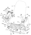
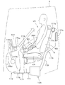
- a work machine includes a driver's seat, an armrest disposed to the side of the driver's seat, an operation lever disposed to the front of the armrest, and a side of the operation lever. And a jog dial. Further, the jog dial is disposed at a position where the operator sitting on the driver's seat can operate the operation lever and the jog dial while placing an arm on the armrest.
- a console provided with the jog dial is provided, and the operation tool mounting surface, which is a surface on which the jog dial is attached in the console, is inclined upward as it goes forward. Moreover, the said operation tool attachment surface inclines in the side which distances from a driver's seat as it goes back.
- the display device may be disposed in front of the jog dial, and the jog dial may be an operating tool for operating the display device. Further, the jog dial is disposed at a position within a field of view of an operator who is seated at the driver's seat and browses the display device. .
- a work machine includes a cabin, a driver's seat disposed in the cabin, and a console disposed between a side wall portion of the cabin and the driver's seat.
- the console has a console cover having a projection projecting toward the side wall of the cabin, and a console support to which the console cover is attached, the projection being greater than the projection on the side wall of the cabin It is attached to the said console support part in the state which overlapped with at least one part of the part arrange
- the said 1st operation tool which an operator operates is provided in the said protrusion part.
- an operating tool mounting surface on which the first operating tool is mounted is provided on the surface of the projecting portion on the side of the operator who is seated in the driver's seat, and the operating tool mounting surface is inclined upward toward the front. And is inclined rearward toward the side wall of the cabin.
- the control device further includes an operation lever disposed between the console and the driver's seat, and an arm rest disposed behind the operation lever, wherein the first operation tool is a side of the operation lever and of the operation lever. It is arranged in the vicinity.
- the first operating tool is disposed at a position where the operator sitting on the driver's seat can operate the operation lever and the first operating tool while placing an arm on the armrest.
- the display device may be disposed in front of the first operation tool, and the first operation tool may include a jog dial for operating the display device.
- the console cover has a first divided body and a second divided body separately attached to the console support portion, and the first divided body has the projecting portion, and the projecting portion The portion is attached to the console support portion in a state where it overlaps in plan view with at least a part of the side wall portion of the cabin.
- the console is provided with a lever provided so as to be able to swing in the back and forth direction
- the console cover is provided with a guide groove through which the lever is inserted and which allows swinging operation in the front and back direction of the lever.
- the guide groove is formed across the first divided body and the second divided body.
- the console cover extends in the front-rear direction along the side wall of the cabin, and the protrusion is provided at the front end of the console cover.
- the manufacturing method of the working machine which concerns on another aspect is a manufacturing method of the said working machine, Comprising: The part which includes the said side wall part in the said cabin is hung down from the upper direction, The said driver's seat and the said console support in the said cabin And a second step of attaching a portion of the console cover including the projecting portion to the console support portion after the first step.
- a work machine includes a driver's seat, a display device provided diagonally in front of the driver's seat, and a portable terminal provided below the display device and holding a portable terminal And a holding unit.
- the mobile terminal holding unit holds the mobile terminal in a state in which an operator seated on the driver's seat can visually recognize at least a part of the display surface of the mobile terminal.
- the display device is disposed to be inclined with respect to the front-rear direction so that the display surface of the display device faces the side of the operator who is seated at the driver's seat, and the portable terminal holding unit The portable terminal is held in a state of being inclined with respect to the front-rear direction so that the display surface faces the side of the operator who is seated at the driver's seat.
- the power supply socket which can be specified for charge of the said portable terminal is provided in the vicinity of the said portable terminal holding part.
- the jog dial is disposed at a position where the operator sitting on the driver's seat can operate the operation lever and the jog dial while placing an arm on the armrest.
- the display apparatus is equipped with the ventilation duct which has a blowing outlet which blows out air-conditioning air, and the said display apparatus is attached to the said ventilation duct. Moreover, it has an interior member which covers the said air flow duct, and the said interior member has a drink holder holding a drink container.
- a work machine including: an air conditioner main body; a first air duct having a first blowout portion for blowing out conditioned air from the air conditioner main body; the air conditioner main body and the first air duct
- a connection duct for connecting the plurality of duct members along the air guide path direction, and at least one of the plurality of duct members includes the duct member.
- connection duct includes a first duct member and a second duct member connecting the air conditioner main body and the first duct member, and the second duct member advances and retracts with respect to the first duct member.
- first duct member has a first air guide portion to which the second duct member is connected
- the air conditioner main body has a blower port to which the second duct member is connected
- a third cushion material is provided at a connection portion with the second duct member, and a first cushion material is provided at a connection portion between the second duct member and the first air guide portion.
- connection duct includes the first duct member, and a third duct member connecting the first duct member and the first air duct, and the third duct member is connected to the first duct member. It can expand and contract in the direction to move back and forth.
- the first duct member has a second air guide portion to which the third duct member is connected, and the first air duct has an inlet to which the third duct member is connected, A connection portion between the second air guide portion and the third duct member is provided with a second cushion material, and a connection portion between the third duct member and the intake port is provided with a fourth cushion material. Further, the second air guide portion is inserted into the inside of the third duct member, and the other end side of the third duct member is inserted into the inside of the intake.
- the air conditioner further includes a second air duct having a second blowout portion for blowing out the conditioned air from the air conditioner main body, and the first duct member has a duct connection portion to which the second air duct is connected.
- the air-conditioner body further comprises: an airframe, a cabin mounted on the airframe, and the steps attached to the airframe to form a floor portion of the cabin, the air conditioner main body being attached to the air-flowing step Is attached to the cabin.
- a working machine is a prime mover, a fuel tank for storing fuel for the prime mover, an airframe on which the prime mover and the fuel tank are mounted, and a fuel to be supplied to the fuel tank.
- a connecting pipe for connecting the side surface of the fuel tank and the fueling unit, and the vehicle body includes the arrangement side of the prime mover and the oiling unit and the arrangement side of the fuel tank It has a partition plate provided with a partition and a through hole through which the connection pipe passes.
- the fuel tank has an inflow pipe portion to which fuel flows in on a side surface corresponding to the through hole
- the fueling portion has a supply pipe portion for supplying fuel to the connection pipe
- the connection pipe is A first portion extending from the inflow tube portion toward the through hole and passing through the through hole, and a second portion extending upward from the first portion and connected to the supply tube portion Have.
- the axial direction of the inflow pipe portion is substantially parallel to the plate surface normal direction of the partition plate.
- an air vent pipe is provided which connects the upper portion of the fuel tank and the fueling portion or the connection pipe and removes the air in the fuel tank.
- the air vent pipe is provided in an inclined shape moving upward as it goes from the fuel tank to a connection portion with the fuel supply portion or the connection pipe.
- the partition plate is fixed to the body and has a main recess having a first recess which can insert a part of the connection pipe in a radial direction, and is attached to the main partition and cooperates with the first recess.
- a secondary partition plate having a second recess that forms the through hole.
- the refueling portion has a sub tank capable of storing fuel, and a refueling port for injecting the fuel into the sub tank. Moreover, it is a cover which covers the said subtank, Comprising: The tank cover which prevents that the heat of the said prime mover leaks from the clearance gap of the exterior member which comprises the exterior of the body of a working machine is provided. Further, the tank cover has a guide path for guiding the fuel dropped from the fuel supply port to the outside of the machine body.
- a work machine includes a cabin, an airframe on which the cabin is mounted, a first cover member disposed to the side of the cabin and containing equipment, and the first cover member.
- a cover body having a cover member and a second cover member disposed between the cabin and openable and closable, and a control device accommodated in the second cover member.
- the said 2nd cover member is detachable in the state which mounted the said cabin.
- the frame member includes a frame member disposed in the second cover member and attached to the machine body, the frame member including a cover attachment portion for attaching the second cover member, and an apparatus attachment portion for attaching the control device.
- the vehicle further includes a motor mounted on the body, a bonnet covering the motor, and a support frame erected on the body to support the bonnet, the frame member being attached to the support frame And a second frame constituent member fixed at one end side to the first frame constituent member and attached at the other end side to the body.
- a work machine includes: a swing base on which a motor is mounted at the rear; and a reinforcing rib provided on the swing base from the front to the rear, The reinforcing rib is at least a rear portion formed of cast steel.
- a motor room in which the motor is mounted on the revolving base is provided, and the reinforcing rib is formed of a front rib made of a sheet metal extending from the front of the revolving base to the front of the engine room And a cast steel rear rib provided so as to project rearward from the rear of the front rib.
- the rear rib has a motor support portion for supporting the motor.
- the rear rib has a through hole which penetrates the rear rib in the horizontal direction.
- the front rib and the rear rib partially overlap in a side view, and the front rib penetrates the front rib in the horizontal direction and communicates with the through hole. It has a through hole. Further, the through hole is a pipe through hole through which piping is passed. Further, the rear rib has a front portion overlapping with the front rib in a side view, and the rear portion is formed to be lower in height as it goes to the rear.
- the reinforcing rib includes a first rib provided on the left side of the turning base and a second rib provided on the right side of the turning base, and at least one of the first rib and the second rib
- the rear part is formed of cast steel.
- An exhaust pipe for exhausting exhaust gas and air introduced from the gap to the atmosphere including a porous pipe portion having a large number of small holes, an outer cylinder covering the periphery of the porous pipe portion, And a sound absorbing material filled between the perforated pipe portion and the outer cylinder.
- the porous pipe portion is formed of a punching metal, and the burrs of the many small holes are disposed on the outer cylinder side.
- a blocking material is provided between the sound absorbing material and the porous pipe portion for blocking the sound absorbing material from intruding into the porous pipe portion through the large number of small holes.
- the sound absorbing material is glass wool, and the blocking material is stainless wool wound around the outer peripheral surface of the perforated pipe portion.
- the exhaust system further includes a hood constituting a motor chamber in which the motor is accommodated, and an exhaust gas purification device for purifying exhaust gas discharged from the motor, and the exhaust conduit is disposed on the exhaust side of the exhaust gas purification device.
- the perforated pipe portion and the outer cylinder are provided in the motor chamber.
- the exhaust pipe is connected to the exhaust side of the exhaust gas purification device and extends upward, and a second pipe extending from a top of the first pipe portion in a direction inclined with respect to the vertical direction.
- a tube portion, the porous tube portion is vertically extended at a position eccentric to the axis of the first tube portion, and the lower portion of the exhaust tube is the second tube It is bent towards the part.
- the exhaust pipe has a skirt portion in which a gap with the second pipe portion is enlarged as the second pipe portion is inserted and goes downward.
- the outer cylinder and the machine body of a working machine are connected, and the supporting member which supports the said outer cylinder and the said exhaust pipe is provided.
- a work machine including: a machine body; a motor mounted on the machine body; a partition member separating a motor room accommodating the motor and a front upper portion of the motor room; A partition plate disposed below the member and partitioning the lower front of the motor chamber, a grommet provided above the partition plate and through which piping is inserted, and the grommet provided on the partition member And a seal body pressed to the side of the partition plate.
- a cabin provided on the opposite side of the partition member to the motor room side and an air conditioner main body provided in the cabin are provided, and piping connected to the air conditioner main body is inserted through the grommet.
- the partition plate is provided with a recessed portion which is recessed downward from the upper end and into which the grommet is inserted.
- the grommet is provided with a retaining plate attached to the partition plate for retaining the grommet from the notched concave portion, and the retaining plate abuts on the lower surface and the seal body contacts the upper surface. It has a presser plate part in contact. Further, the grommet has a plurality of pipe insertion parts through which the pipes pass, and the plurality of pipe insertion parts are provided such that adjacent pipe insertion parts are vertically displaced.
- a work machine including: a machine body; a motor mounted on the machine body; a driver's seat disposed in front of the motor; and a bonnet forming a motor room accommodating the motor.
- the first front leg and the second front leg which are formed spaced apart in the widthwise direction of the vehicle and arranged so that the thickness direction corresponds to the widthwise direction of the body, and the first front leg and the second front leg And at least one rear leg disposed at the rear, and the partition plate is a metal plate fixed across the first front leg and the second front leg.
- the thickness of the first front leg and the thickness of the second front leg are thinner than the thickness of the rear leg.
- at least one of the first front leg and the second front leg is in contact with and fixed to the back surface of the partition plate.
- the first front leg is fixed so that the front surface abuts against the rear surface of the partition plate in a face-to-face contact
- the second front leg is fixed by abutting the side surface of the partition plate in the machine body width direction It is done.
- a work machine is an airframe and a cabin mounted on the airframe, the work machine having an opening that opens downward to the lower end side of the cabin and communicates with the cabin of the cabin.
- a cabin having a seal attachment surface to be formed, an annular seal member provided so as to surround the opening and attached to the seal attachment surface, and a seal provided on the airframe side and in contact with the seal member And a contact surface.
- the airframe further comprises a step of forming a floor surface of the cabin, the step including a flat main plate having a first contact surface that constitutes the seal contact surface on an upper surface.
- the cabin has a front mounting device supported by the step at the front of the cabin, and the first contact surface is a first seal provided on one side of the step in the vehicle width direction A front surface of the vehicle body, a second seal surface provided on the other side in the machine width direction, and a third seal surface connecting the first seal surface and the front portion of the second seal surface; And a rear side of the third sealing surface.
- a motor mounted on the vehicle body, and a partition member for separating a motor room containing the motor from the cabin of the cabin, the partition member is provided on one side of the vehicle in the width direction of the vehicle.
- a third contact surface provided on the other side of the body width direction, wherein the seal material contacts the first contact surface to the second contact surface and the second contact surface 2 Abut against the third contact surface from the sealing surface.
- the support frame is provided upright on the body and supports the partition member, the support frame includes an upper plate for supporting a rear portion of the cabin, and the upper plate is in contact with the seal member.
- the seal material has a fourth contact surface, and the seal material contacts the third contact surface from the second contact surface through the fourth contact surface.
- the cabin has a rear mounting device supported by the upper plate at the rear of the cabin, and the rear mounting device is disposed at the rear of the fourth contact surface.
- a work machine includes a cabin, a step of forming a floor surface of the cabin, and a harness obtained by bundling electrical wiring, and the step forms the floor surface.
- the step is formed by a first edge portion and a second edge portion which are open and opposed to each other, and the step is a first portion at which the first edge portion of the main plate is formed and a second portion at which the second edge portion is formed.
- the second part is detachably fixed to the second part to close the second notch.
- first vertical wall connected to the first portion
- second vertical wall connected to the second portion
- connecting wall connecting the first vertical wall and the second vertical wall.
- a connecting member is provided, and the harness is routed through a space surrounded by the second plate, the first vertical wall, the connecting wall, and the second vertical wall.
- the side wall part of the said cabin is mounted via the sealing material on the said main plate and the said 2nd board.
- a work machine includes an air conditioner main body and a cabin having an external air introducing portion for introducing external air into the air conditioner main body, and the external air introducing portion communicates with the air conditioner main body.
- the third outside air inlet, the second outside air inlet, and the first outside air inlet are disposed at positions not aligned in a straight line.
- the third outside air introduction port is a gap between the outer edge portion of the outer layer member and the middle layer member. Further, the third outside air introduction port includes a lower gap which is a gap between the lower edge portion of the outer layer member and the middle layer member.
- the third outside air introduction port is an upper gap which is a gap between the upper edge portion of the outer layer member and the middle layer member, and a gap between the front edge portion of the outer layer member and the middle layer member
- the width of the front gap is larger than the width of the upper gap and the lower gap, including a front gap.
- the second outside air introduction port is formed of a plurality of elongated holes arranged in parallel with each other in the vertical direction, and the middle layer member is formed in the upper edge portion of each elongated hole in the vertical direction. It has a bowl-shaped portion inclined to the inner layer member side.
- the opening areas of the first outside air inlet, the second outside air inlet, and the third outside air inlet are substantially equal.
- the first outside air inlet is disposed above the second outside air inlet.
- the air conditioner main body is disposed in the vicinity of the side of the outside air introducing portion, and is in communication with the first outside air introducing port through the outside air introducing duct.
- a work machine including an airframe, a support attached to the airframe, a movable body supported by the support so as to be adjustable in the front-rear position, and the movable body
- the rearward movement of the driver's seat is restricted by the abutment of the operating lever, the driver's seat supported by the movable body so as to be adjustable in the back and forth position, at least one stopper provided on the driver's seat, and the stopper. And at least one abutment member.
- the driver's seat moves the movable body to the rear end side of the moving area, and the rear position of the stopper is restricted by the contact member, so that the position can be adjusted backward with respect to the movable body Have.
- the first support device includes a first rail device for supporting the movable body so as to be adjustable in the back and forth position; and a second rail device for supporting the driver's seat on the movable body so as to be adjustable in the back and forth position; The rail device is locked so as not to move back and forth in a state in which there is a gap between the stopper and the contact member after the movable body is moved backward and the stopper contacts the contact member. After the stopper abuts on the contact member, the second rail device is locked so as not to move back and forth in a state in which a gap is formed between the stopper and the contact member.
- the stopper can be adjusted in the longitudinal direction.
- a suspension for supporting the driver's seat is provided, and the contact member is formed to be vertically long.
- a motor provided at the rear of the driver's seat, and a partition plate separating a motor room accommodating the motor from the driver's seat side, the contact member being attached to the partition plate .
- the partition plate further includes a first rail device for supporting the movable body on the support table such that the front and rear positions can be adjusted, and a second rail device for supporting the driver's seat on the movable body such that the front and rear positions can be adjusted.
- a first rail device for supporting the movable body on the support table such that the front and rear positions can be adjusted
- a second rail device for supporting the driver's seat on the movable body such that the front and rear positions can be adjusted.
- the operator can operate the jog dial with the arm placed on the armrest, and can easily transfer the hand to the operation lever and the jog dial. This can reduce the burden on the operator's operation.
- the working machine when assembling the cabin, the working machine has the projecting part overlapping with a part of the side wall part of the cabin by removing the console cover including the projecting part from the console supporting part.
- the cabin can be assembled by hanging it down from above.
- the console cover including the projecting portion to the console support portion after assembling the cabin, the cabin can be assembled without damaging the projecting portion.
- the operator can easily check not only the display device but also the screen of the portable terminal during work. This can enhance the comfort around the driver's seat.
- contraction state an assembly and removal of a connection duct can be performed easily.
- connection pipe is connected to the side surface of the fuel tank. Therefore, the connection pipe can be inserted into the through hole of the partition plate.
- the partition structure between the arrangement side of the prime mover and the arrangement side of the fuel tank can be simplified.
- the control device can be accessed by opening the second cover member. Thereby, maintenance of the control device can be easily performed.
- the rear part of a reinforcement rib is formed with cast steel, the rear part of a reinforcement rib can be formed in the shape where width is wide and height is low. As a result, sufficient strength can be provided even if the height of the reinforcing rib is lowered, and the degree of freedom in the arrangement of the prime mover can be increased by lowering the reinforcing rib. In addition, since the height can be lowered, the wind flowing below the prime mover can easily flow, and the cooling performance can be improved.
- the structure around the periphery of the porous pipe portion provided in the exhaust pipe is covered with the outer cylinder and the sound absorbing material is filled between the porous pipe portion and the outer cylinder.
- the reduction can be achieved.
- the grommet through which the piping is inserted is provided on the upper portion of the partition plate, and the grommet is pressed by the seal body provided on the partition member. It is easy to assemble installed piping.
- the partition plate is made to function as one of the strength members and the machine width required for the support frame
- the strength of the direction can be reduced.
- the strength in the front-rear direction of the support frame can be improved by matching the thickness direction of the first front leg and the thickness of the second front leg in the machine body width direction.
- the strength of the support frame in the machine width direction and the front-rear direction can be improved, and the weight of the support frame can be reduced.
- the seal member provided so as to surround the opening at the lower end of the cabin abuts on the seal contact surface provided on the airframe side over the entire circumference, whereby the cabin is made into the cabin. Dust intrusion prevention and sound intrusion reduction can be achieved.
- the second notch can be closed by the second plate, so the harness can be easily assembled. be able to.
- the external air introducing portion has a three-layer structure, and the introduction port of the external air formed by each member constituting each layer is displaced, thereby enhancing the water intrusion preventing effect to the air conditioner main body. be able to.
- the position control to the back of both a movable body and a driver's seat can be performed by a stopper and an abutting member.
- FIG. 44 is a cross-sectional view taken along line X1-X1 in FIG.
- FIG. 44 is a cross-sectional view taken along line X2-X2 in FIG.
- FIG. 44 is a side perspective view showing an outer layer member. It is the perspective view which looked at a middle layer member from the bottom.
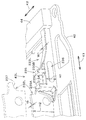
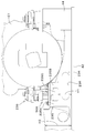
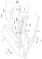
- connection duct It is a side view of the room of a cabin. It is a top view of the room of a cabin. It is a perspective view of a connection duct. It is a top view of a connection duct. It is a plane sectional view of a connection duct. It is back surface sectional drawing of a 1st airflow guidance part and a 2nd duct member. It is an expanded sectional view of the connection portion of the 2nd duct member. It is side surface sectional drawing of a 2nd airflow guidance part and a 3rd duct member. It is an expanded sectional view of the connection portion of the 3rd duct member. It is a top view which shows the state at the time of attachment or detachment of a connection duct.
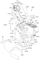
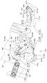
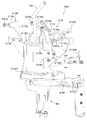
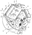
- FIG. 1 is a schematic side view showing the overall configuration of a work machine 1 according to the present embodiment.
- FIG. 2 is a schematic plan view of the work machine 1 with the work device omitted.
- a backhoe which is a turning work machine is illustrated as the work machine 1.
- the working machine 1 includes a machine body (pivot table) 2, a traveling device 3, and a working device 4.
- a cabin 5 is mounted on the fuselage 2.
- a driver's seat (seat) 6 on which an operator (driver) is seated is provided in the cabin of the cabin 5.
- the driver's seat 6 is surrounded by the cabin 5.
- the front side (direction of arrow A1 in FIG. 1 and FIG. 2) of the operator sitting on the driver's seat 6 of the work machine 1 is forward and the rear side of the operator (direction of arrow A2 in FIG. Is described with the left side of the operator (front side in FIG. 1, the direction of arrow B1 in FIG. 2) as the left, and the right side of the operator (rear side in FIG. 1, the direction of arrow B2 in FIG. 2) as right.
- the horizontal direction which is a direction orthogonal to the front-rear direction K1 will be described as the machine width direction K2 (see FIG. 2).
- the direction from the central part in the width direction of the fuselage 2 to the right part or the left part will be described as the direction outside the body.
- the extra-body direction is the direction away from the center in the width direction of the airframe 2 in the airframe width direction K2.
- the direction opposite to the direction outside the aircraft will be described as the direction inside the aircraft.
- the inside of the vehicle is the direction in which the widthwise direction of the airframe 2 approaches the center of the airframe 2 in the airframe width direction K2.
- the traveling device 3 has a traveling frame 9 and a traveling mechanism 10.
- the traveling mechanism 10 is configured by a crawler type traveling mechanism driven by a hydraulic motor.
- the traveling device 3 is a crawler-type traveling device.
- the traveling mechanism 10 is provided on the left side and the right side of the traveling frame 9.
- a dozer device 7 is mounted at the front of the traveling device 3. The dozer device 7 can be raised and lowered by a hydraulic cylinder.
- the working device 4 has a boom 15, an arm 16 and a bucket (working tool) 17.
- the base of the boom 15 is pivotally attached to the swing bracket 14 so as to be rotatable (pivotable in the vertical direction) about a horizontal axis (an axial center extending in the machine width direction K2).
- the swing bracket 14 is rotatably supported by a support bracket 18 provided at the front of the machine body 2 about a longitudinal axis (an axial center extending in the vertical direction).
- the arm 16 is pivotally attached to the tip end side of the boom 15 so as to be rotatable (swingable back and forth or up and down) around a horizontal axis.
- the bucket 17 is provided on the tip side of the arm 16 so as to be able to perform a squeeze operation and a dumping operation.
- the work machine 1 can mount other work (hydraulic attachment) that can be driven by a hydraulic actuator, instead of or in addition to the bucket 17.
- hydraulic breakers, hydraulic crushers, angle blooms, earth augers, pallet forks, sweepers, mowers, snow blowers and the like can be exemplified.
- the swing bracket 14 swings around the longitudinal axis by the expansion and contraction of the hydraulic cylinder.
- the boom 15 swings by the expansion and contraction of the boom cylinder C3.
- the arm 16 swings by extension and contraction of the arm cylinder C4.
- the bucket 17 performs a squeeze operation and a dumping operation by extension and contraction of a bucket cylinder (work implement cylinder) C5.
- the boom cylinder C3, the arm cylinder C4, and the bucket cylinder C5 are configured by hydraulic cylinders (hydraulic actuators).
- the vehicle body 2 is supported on a traveling frame 9 via a pivot bearing 8 so as to be rotatable (pivotable to the left and right) about a longitudinal axis.
- the airframe 2 has a pivoting frame 41 which becomes a skeleton.
- the swing frame 41 has a swing base 42 that constitutes the bottom of the airframe 2.
- the motor E1 is mounted at the rear of the pivoting board 42 (see FIG. 6).
- the pivoting substrate 42 is formed of a thick plate, and as shown in FIG. 4, the lower surface side is bolted to the outer race 8 A of the pivoting bearing 8.
- the inner race 8 B of the pivot bearing 8 is bolted to the traveling frame 9.
- the outer race 8A and the inner race 8B are relatively rotatably coupled via a ball.
- a turning motor M1 which rotationally drives the turning base 42 is attached.
- a support bracket 18 is fixed to the front of the pivoting base 42 in a projecting manner.
- the support bracket 18 is disposed in front of the swing motor M1.
- reinforcing ribs 43 are provided from the front (one end side) to the rear of the turning base 42 (toward the motor E1).
- the reinforcing rib 43 is fixed by welding to the turning base 42 and reinforces the turning base 42.
- the reinforcing rib 43 includes a first rib 43L provided on the left side of the turning base 42 and a second rib 43R provided on the right side of the turning base 42.
- a block-shaped first weight attaching portion 44 long in the machine body width direction K2 is fixed to the rear of the turning base 42.
- the first rib 43L (the reinforcing rib 43) has a front rib 232L and a rear rib 233L, and is provided from the left portion of the rear portion of the support bracket 18 to the left portion of the first weight attachment portion 44.
- the second rib 43R (reinforcing rib 43) has a front rib 232R and a rear rib 233R, and is provided from the right portion of the rear portion of the support bracket 18 to the right portion of the first weight attachment portion 44.
- a rectangular second weight attachment portion 45 is provided upright. Weights 46 are attached to the first weight attachment portion 44 and the second weight attachment portion 45 (see FIG. 6). The weight 46 is provided at the rear of the airframe 2.
- a partition plate 47 is provided on the rear side of the front and rear center portion of the turning base 42.
- the partition plate 47 has a main partition plate 48 and a secondary partition plate 49.
- the main partition plate 48 extends in the machine body width direction K2 across the first rib 43L from the left side surface of the second rib 43R and across the left end of the turning base 42.
- the main partition plate 48 is fixed by welding on the turning base 42 and is erected.
- the sub partition 49 is overlapped and attached to the rear surface of the main partition 48 at the left side of the turning base 42.
- a first opening 31 and a second opening 32 are formed at the rear of the pivoting substrate 42, and are formed of edges of a substantially rectangular shape formed through the pivoting substrate 42.
- the first opening 31 and the second opening 32 discharge the cooling air after cooling the prime mover E1.
- the first opening 31 is formed at the rear of the main partition plate 48 and between the first rib 43L and the second rib 43R.
- a first cover plate 33 formed of a porous plate having a large number of holes is disposed in the first opening 31 so as to cover the opening.
- the second opening 32 is formed on the left of the first opening 31 and on the left of the first rib 43L.
- a second cover plate 34 formed of a porous plate having a large number of holes is disposed in the second opening 32 so as to cover the opening.
- the rear of the swing frame 41 is covered by a weight 46.
- a turning cover (exterior member) 51 attached to the turning frame 41.
- An auxiliary cover (exterior member) 54 is provided at the left rear of the turning frame 41.
- the auxiliary cover 54 covers the pivoting frame 41 from the upper rear of the left side of the pivoting cover 51 to the upper portion of the left of the weight 46.
- the front surface portion of the turning cover 51 is formed with a notch through which the support bracket 18 protrudes.
- the upper left side of the front of the pivoting frame 41 is covered by a step 52.
- the steps 52 are attached to a plurality of step attachment portions 53a to 53g provided on the turning frame 41 (see FIGS. 3 and 6).
- the cabin 5 is mounted on the left side and the front side of the airframe 2.
- the lower surface side of the front part of the cabin 5 is covered with a step 52. That is, step 52 constitutes the floor surface of the cabin 5 (see FIGS. 28 and 29).
- a driver's seat 6 is mounted in front of the motor E1 and at the rear of the step 52.
- the motor E ⁇ b> 1 is mounted at the rear of the airframe 2.
- the prime mover E1 is a diesel engine.
- the prime mover E1 may be a gasoline engine, an LPG engine or an electric motor, or may be a hybrid type having an engine and an electric motor.
- the motor E1 is disposed on the rear side of the cabin 5.
- a hydraulic pump P1 and an exhaust gas purification device D1 are provided on the left side of the motor E1.
- the hydraulic pump P1 is driven by the power of the prime mover E1.
- the hydraulic pump P1 discharges hydraulic oil (hydraulic pressure) for driving a hydraulic motor, a hydraulic cylinder, or the like equipped to the work machine 1.
- the hydraulic pump P1 also discharges a pilot pressure for operating the hydraulic valve and a hydraulic pressure for signal.
- the hydraulic pump P1 is configured of, for example, a plurality of pumps.
- the exhaust gas purification device D1 is a device that purifies the exhaust gas discharged from the motor E1, and is, for example, a DPF (Diesel particulate filter).
- the prime mover E1 is supported by a plurality of supports (first support 50A, second support 50B, third support 50C, and fourth support 50D) shown in FIG.
- the first support 50A is provided on the left side of the turning base 42 and on the rear of the main partition plate 48, and supports the left front side of the motor E1.
- the second support 50B is provided on the center side of the turning base 42 in the machine width direction K2 and behind the main partition plate 48, and supports the right front side of the motor E1.
- the third support 50C is fixed to the left of the first weight attachment portion 44 and supports the left rear side of the motor E1.
- the fourth support 50D is disposed on the right side of the second weight attachment portion 45 and is fixed on the first weight attachment portion 44, and supports the right rear side of the motor E1.
- the motor E1 is covered by a bonnet 22.
- the bonnet 22 forms a motor room E2 that houses the motor E1.
- the motor room E2 is formed on the turning base 42.
- the exhaust gas purification device D1 is provided in the motor chamber E2.
- the bonnet 22 has a partition member (partition plate) 22A covering the front (upper front) of the prime mover E1 and a bonnet rear part 22B covering the rear of the prime mover E1.
- a support frame 11 for supporting the bonnet 22 is provided in the bonnet 22, a support frame 11 for supporting the bonnet 22 is provided.
- the support frame 11 is provided upright on the machine body 2.
- the partition wall member 22A is a member that separates the motor room E2 from the arrangement side of the driver's seat 6 (the area closer to the driver's seat 6 than the motor room E2).
- the partition wall member 22A is a member that separates the motor room E2 from the cabin 5 interior.
- the partition member 22A is made of, for example, a sheet metal. By forming the partition wall member 22A with a sheet metal, the sound insulation is improved as compared to the resin partition wall member.
- a support bracket for supporting wiring components such as a harness can be easily attached to the partition wall member 22A by welding, screwing, or the like. Further, the strength of the machine body 2 can be improved by the partition wall member 22A.
- the partition member 22A is fixed to the support frame 11. Further, a partition plate 47 is provided below the partition wall member 22A. The partition plate 47 partitions the lower front of the motor room E2.
- the bonnet rear portion 22B is vertically swingably supported by the support frame 11, and swings up and down to open and close the motor room E2.
- a weight 46 is disposed below the bonnet rear portion 22B, and the weight 46 covers the rear of the lower portion of the prime mover E1.
- the left end between the partition wall member 22A and the bonnet rear portion 22B is open toward the vehicle exterior, and this open portion is, as shown in FIG. It is blocked by the lower part.
- the lower left side of the prime mover E1 is covered by the left side portion of the turning cover 51 and the auxiliary cover 54.
- the support frame 11 includes a plurality of frame attachment portions (a first frame attachment portion 55A, a second frame attachment portion 55B, a third frame attachment portion 55C, 4 frame attachment portion 55D).
- the first frame attachment portion 55A is fixed to the left portion of the upper end of the main partition plate 48 and the upper end of the reinforcing plate 56A erected on the turning base 42.
- the second frame attachment portion 55 B is fixed to the right portion of the upper end of the main partition plate 48 and the upper end of the reinforcing plate 56 B erected on the turning base 42.
- the third frame attachment portion 55C is disposed on the left side of the first weight attachment portion 44 and is provided upright on the turning base 42.
- the fourth frame attachment portion 55D is provided upright on the right side of the first weight attachment portion 44.
- the support frame 11 has a plurality of legs (a first front leg 57L, a second front leg 57R, a first rear leg 58L, a second rear leg 58R) and an upper plate 59. .
- the plurality of legs and the upper plate 59 are formed of a plate material.
- the first front leg 57L and the second front leg 57R are disposed on the front side of the motor E1.
- the first front leg 57L and the second front leg 57R are disposed at an interval in the machine width direction K2.
- the first front leg 57L and the second front leg 57R are disposed in such a manner that the board thickness direction S1 coincides with the machine width direction K2.
- the first front leg 57L is fixed by welding or the like with its front surface abutting against the rear surface of the left portion of the partition wall member 22A.
- the left portion of the partition member 22A protrudes leftward from the first front leg 57L.
- the first front leg 57L has a main body 62a and an upper portion 62b.
- a first front mounting plate 60L is fixed to the lower end of the main body portion 62a, which extends in the longitudinal direction and is bolted to the first frame mounting portion 55A.
- the upper portion 62b extends rearward from the upper portion of the main body 62a.
- a notch 62c is formed at the front of the upper portion 62b.
- the notch 62c is formed on the upper surface side of the upper portion 62b.
- the second front leg 57R is disposed on the right side of the partition wall member 22A.
- the second front leg 57R is disposed closer to the front than the first front leg 57L.
- the right end of the partition member 22A is welded and fixed to the left side surface of the second front leg 57R.
- the second front leg 57R has a main portion 63a and an upper portion 63b.
- a second front mounting plate 60R is fixed to the lower end of the main body portion 63a, which extends in the longitudinal direction and is bolted to the second frame mounting portion 55B.
- the upper portion 63b extends rearward from the upper portion of the main body portion 63a.
- the first front mounting plate 60L and the second front mounting plate 60R are connected by a connecting plate 64.
- the upper plate 59 is fixed to the upper portion 62b of the first front leg 57L and the upper portion 63b of the second front leg 57R.
- the top plate 59 and a cover plate 20 provided on the rear end side of the top plate 59 so as to project upwards close the gap between the partition member 22A and the bonnet rear portion 22B.
- a mounting plate 74 is fixed to the upper right side of the upper plate 59.
- the first rear leg 58L and the second rear leg 58R are disposed on the rear side of the motor E1. As shown in FIG. 10, the first rear leg 58L and the second rear leg 58R are disposed at an interval in the machine width direction K2. The first rear leg 58L and the second rear leg 57R are disposed such that the board width direction S2 coincides with the machine width direction K2. As shown in FIG. 12, the upper portion of the first rear leg 58L is attached to a mounting member 65 fixed to the left side of the upper plate 59. As shown in FIG. A first rear mounting plate 61L bolted to the third frame mounting portion 55C is fixed to the lower end of the first rear leg 58L. As shown in FIG. 10, the first rear leg 58L is positioned closer to the vehicle interior than the first front leg 57L.
- the upper portion of the second rear leg 58R is fixed to the lower surface of the upper plate 59.
- a second rear mounting plate 61R bolted to the fourth frame mounting portion 55D is fixed.
- the second rear leg 58R is positioned closer to the vehicle exterior than the second front leg 57R.
- the upper portion of the second rear leg 58R and the mounting member 65 are connected by a connecting plate 66.
- At least one leg on the rear side of the support frame 11 may be provided.
- the thickness t1 of the first front leg 57L and the thickness t2 of the second front leg 57R are greater than the thickness t3 of the first rear leg 58L and the thickness t4 of the second rear leg 58R. thin.
- weight reduction of the support frame 11 is achieved.
- the weight reduction of the support frame 11 is achieved by fixing the partition member 22A made of sheet metal over the first front leg 57L and the second front leg 57R to increase the strength in the machine width direction K2, and the first front leg 57L and the second front leg.
- the thickness t1 of the first front leg 57L and the thickness t2 of the second front leg 57R may be the same or different.
- the partition member 22A substantially includes a partition main body 67 that divides the interior of the cabin 5 from the motor room E2, an upper extension portion 68 extending rearward from the upper end of the partition main body 67, and a partition And a lower extending portion 69 extending forward from the lower end of the main body 67.
- the partition main body 67 has a first portion 67A on the upper side and a second portion 67B on the lower side.
- the first portion 67 ⁇ / b> A and the second portion 67 ⁇ / b> B are formed in an inclined shape moving rearward as going upward.
- the inclination angle of the first portion 67A and the second portion 67B with respect to the vertical direction is larger than that of the second portion 67B. Therefore, the partition wall member 22A is bent in the middle.
- the left portion of the upper extension 68 is inserted into the notch 62c and welded and fixed onto the upper portion 62b of the first front leg 57L.
- a left seal block 70L is provided on the left of the upper extension 68
- a right seal block 70R is provided on the right of the upper extension 68.
- the seal blocks 70L, 70R are formed of elastic members and are deformable.
- the first front leg 57L and the second front leg 57R are processed products formed by cutting a plate material by laser cutting or the like. By forming the first front leg 57L by laser cutting or the like, the shape of the front surface (cut surface) of the first front leg 57L can be precisely matched to the shape of the rear surface of the partition member 22A. The front surface can be brought into contact with the back surface of the partition member 22A with high accuracy.
- the end of the partition wall member 22A is welded and fixed to the side surface of the second front leg 57R.
- the present invention is not limited thereto.
- the second front leg 57R may be welded and fixed to the rear surface of the partition wall member 22A.
- the partition wall member 22A has an inspection opening 71 for accessing the interior of the motor room E2, and a closing plate 72 for closing the inspection opening 71.
- the inspection opening 71 is formed to penetrate the first portion 67A.
- the closure plate 72 is bolted to the first portion 67A from the front side.
- the closing plate 72 is in contact with the partition wall member 22A via a sealing material provided around the inspection opening 71.
- the closing plate 72 is provided with a handle member 73.
- the handle member 73 is provided at an intermediate portion in the machine body width direction K2 of the upper portion of the closing plate 72, and protrudes upward from the closing plate 72.
- a left console 79 ⁇ / b> L is provided on the left side of the driver's seat 6.
- the console 79L is provided with an unload lever 76, a left operation lever 77L, a left arm rest 78L, and the like.
- the console 79R is provided with a first operation tool 81 including a right operation lever 77R, a right armrest 78R, a dozer lever (lever) 80, and a jog dial 81A, a second operation tool 82, and the like.
- the driver's seat 6 has a seat 6A that supports the buttocks of the operator and a backrest 6B that supports the back of the operator.
- the unloading lever 76 permits the supply of hydraulic fluid to a hydraulic device (for example, a hydraulic cylinder for driving the working device 4 or the swing motor M1 for swinging the machine body 2). Ru.
- the unload lever 76 can swing upward from the state shown in FIGS. 1 and 14.
- the console 79L is swung upward with the lower portion of the rear part as a fulcrum.
- the operation lever 77L and the console 79L do not interfere with the operator getting on and off, and the operator can easily get on and off.
- the cabin 5 has an entrance 29 on the left side for an operator to get on and off, and the entrance 29 can be opened and closed by a door 28.
- the operation lever 77L can operate two operation targets, and, for example, can perform a swing operation of the machine body 2 and a swing operation of the arm 16.
- the control lever 77L is disposed in front of the armrest 78L.
- the armrest 78L is disposed on the left side of the driver's seat 6, and can mount the left arm (a part or all of the forearm (portion from the elbow to the wrist)) of the operator.
- the operator can operate the operation lever 77L with the forearm placed on the armrest 78L.
- the operation lever 77R can also operate two operation targets, and for example, swing operation of the boom 15 and swing operation of the bucket 17 are possible.
- the control lever 77R is disposed between the console 79R and the driver's seat 6 and in front of the armrest 78R.
- the operation lever 77R is located on the side of the jog dial 81A on the driver's seat 6 side.
- the armrest 78R is disposed on the right side of the driver's seat 6, and can mount the right arm (forearm) of the operator. For example, the operator can operate the operation lever 77R with the forearm placed on the armrest 78R.
- the dozer lever 80 is a lever for operating the dozer device 7.
- the dozer lever 80 is disposed to the side of the armrest 78R and to the side (right side) opposite to the driver's seat 6 side.
- a jog dial 81A is disposed in front of the dozer lever 80. That is, the dozer lever 80 is disposed behind the jog dial 81A and on the side of the arm rest 78R.
- the jog dial (first operating tool) 81A is an operating tool for the operator to operate a display device 191 (see FIG. 56) and the like described later.
- the second operation tool 82 is an operation tool for operating the air conditioner equipped in the work machine 1 and includes a power switch 82a for turning on and off the power, a temperature dial 82b for adjusting temperature, and an air volume dial 83c for adjusting air volume. .
- a support 83 is provided below the driver's seat 6.
- the support 83 is attached to the step 52 (body 2).
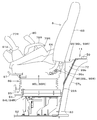
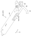
- a movable body 85 is supported on the support 83 via a first rail device (including a first slide rail 84L on the left and a first slide rail 84R on the right) so as to adjust its longitudinal position.
- the driver's seat 6 is supported on the movable body 85 so as to be able to adjust its longitudinal position via the second rail device (including the second slide rail 86L on the left and the second slide rail 86R on the right).
- the movable body 85 has a slide frame 87 attached to the support base 83 via the first slide rails 84L and 84R, and a suspension 88 attached on the slide frame 87.
- the slide frame 87 includes a first mounting portion 87A to which the suspension 88 is attached, a second mounting portion 87L extending leftward from the first mounting portion 87A, and a second extending rightward from the first mounting portion 87A. And 3 mounting portion 87R.
- the console 79L is attached to the second attachment portion 87L, and the console 79R is attached to the third attachment portion 87R.
- the driver's seat 6 is attached to the suspension 88 via the second slide rails 86L, 86R.
- the suspension 88 is a shock absorber that supports the load of the operator acting on the driver's seat 6 and mitigates the transmission of vibrations and impacts from below to the driver's seat 6.
- the suspension 88 may also have a height adjustment mechanism that adjusts the height of the driver's seat 6.
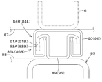
- the first slide rails 84L and 84R are formed long in the front-rear direction K1 and have lower rails 89 and upper rails 90.
- the lower rail 89 is attached to the support 83.
- the upper rail 90 is movably fitted to the lower rail 89 in the front-rear direction K 1 and is attached to the slide frame 87.
- the movable body 85 is movable in the front-rear direction K1 with respect to the support base 83.
- a restricting member 93 is mounted which restricts the rearward movement of the upper rail 90 with respect to the lower rail 89 by abutting on the front end of the lower rail 89.
- the lower rail 89 has a large number of engaging portions 91A spaced in the front-rear direction K1 and formed from the front to the rear.
- an engaging member 92A that engages with the engaging portion 91A is provided in the upper rail 90.
- an operating rod 94 is attached to the upper rail 90.
- the operation rod 94 has one end 94a attached to the upper rail 90 of the left first slide rail 84L and the other end 94b attached to the upper rail 90 of the right first slide rail 84L.
- the operating rod 94 is interlocked with the engaging member 92A, and pulling up the operating rod 94 causes the engaging member 92A to move away from the engaging portion 91A. Thereby, the back and forth movement of the upper rail 90 with respect to the lower rail 89 is permitted.
- the operating force of the operating rod 94 is released, the operating rod 94 is pulled downward by the biasing force of the spring, and the engaging member 92A engages with the engaging portion 91A.
- the second slide rails 86L and 86R are formed long in the front-rear direction K1 and have lower rails 95 and upper rails 96.
- the lower rail 95 is attached to the suspension 88.
- the upper rail 96 is movably fitted to the lower rail 95 in the front-rear direction K 1 and attached to the driver's seat 6.
- the driver's seat 6 can be moved in the front-rear direction K1 with respect to the movable body 85.
- the lower rail 95 has a large number of engaging portions 91B spaced from each other in the front-rear direction K1 and formed from the front to the rear.
- an engagement member 92B engaged with the engagement portion 91B is provided in the upper rail 96.
- the engaging member 92B is engaged with the engaging portion 91B, the back and forth movement of the upper rail 96 with respect to the lower rail 95 is restricted (the second slide rails 86L and 86R are locked).
- an operating rod 97 is attached to the upper rail 96.
- the operation rod 97 has one end 97a attached to the upper rail 96 of the left first slide rail 84L and the other end 97b attached to the upper rail 96 of the right first slide rail 84L.
- the operating rod 97 is interlocked with the engaging member 92B, and pulling up the operating rod 97 causes the engaging member 92B to move away from the engaging portion 91B. Thereby, the back and forth movement of the upper rail 96 with respect to the lower rail 95 is permitted.
- the operating force of the operating rod 97 is released, the operating rod 97 is pulled down by the biasing force of the spring, and the engaging member 92B engages with the engaging portion 91B.
- the position of the driver's seat 6 in the front-rear direction K1 with respect to the movable body 85, the positional relationship between the operator and the control levers 77L and 77R in the front-rear direction K1 can be adjusted.
- the position of the driver's seat 6 can be set so that the operator can operate the operation levers 77L and 77R with a comfortable posture of bending of the elbow.
- the front-rear position of the driver's seat 6 can be adjusted while maintaining the positional relationship between the operator and the operation levers 77L and 77R in the front-rear direction K1.
- the stopper 98 abuts on the abutting member 99, it is possible to restrict the rearward movement of the driver's seat 6. Further, the stopper 98 abuts on the abutment member 99 before the driver's seat 6 interferes with the partition wall member 22A. This can prevent the driver's seat 6 from interfering with the partition wall member 22A.
- the stopper 98 is provided on the left of the rear of the seat 6A and on the right of the rear of the seat 6A.
- the number of stoppers 98 may be one, or three or more.
- the number of abutment members may be provided corresponding to the number of stoppers, or one abutment member may be provided for a plurality of stoppers.
- the stopper 98 is attached to a support bracket 100 attached to a seat frame 6C forming a framework of the driver's seat 6 so as to be positionally adjustable in the front-rear direction K1.
- the stopper 98 has a contact portion 98a that contacts the contact member 99, and a screw shaft 98b that protrudes forward from the contact portion 98a.
- the screw shaft 98 b is a member in which a male screw is formed on the outer peripheral surface of the bar.
- the screw shaft 98b is constituted by a bolt, and the head of the bolt is embedded in the abutment portion 98a.
- the support bracket 100 has a first portion 100a attached to the seat frame 6C and a second portion 100b extending upward from the rear end of the first portion 100a.
- the second portion 100b has a screw hole 102 having an axial center in the front-rear direction K1.
- the screw hole 102 is a hole in which a female screw is formed on the inner peripheral surface of a through hole formed through the support bracket 100.
- a screw shaft 98 b is screwed into the screw hole 102. By screwing (screwing) or screwing back (relaxing) the screw shaft 98b, the position of the stopper 98 relative to the contact member 99 can be adjusted in the front-rear direction K1.
- a lock nut 101 for fixing the position of the stopper 98 is screwed into the screw shaft 98b.
- the contact member 99 is attached to the front side of the partition member 22A.
- the contact member 99 is provided on the upper left portion of the partition member 22A and on the upper right portion of the partition member 22A.
- the left stopper 98L abuts on the left abutment member 99L
- the right stopper 98R abuts on the right abutment member 99R.
- the contact member 99 has a contact plate 99a and a mounting piece 99b fixed to the back surface of the contact plate 99a.
- the mounting piece 99 b is fixed by welding to the closing plate 72.
- the contact plate 99a is vertically elongated from the top to the bottom. Longitudinal means that the length in the vertical direction is longer than the width in the machine body width direction K2.
- the front surface of the contact plate 99a is a contact surface with which the stopper 98 contacts, and is a vertical surface (surface along the vertical direction).
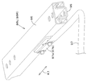
- the partition wall member 22A is provided at the lower portion (the second portion 67B of the partition wall main body 67) with a left first insertion hole 103L formed at a portion corresponding to the first slide rail 84L.
- a right first insertion hole 103R is formed at a portion corresponding to the first slide rail 84R.
- the rear end side of the first slide rail 84L is inserted into the first insertion hole 103L, and the rear end side of the first slide rail 84R is inserted into the first insertion hole 103R.
- the first insertion hole 103L is closed by the left first cover plate 104L
- the first insertion hole 103R is closed by the right first cover plate 104R.
- the first cover plates 104L and 104R are recessed rearward to avoid interference with the first slide rails 84L and 84R. That is, the partition wall member 22A has a first recess 107 which is recessed rearward to insert the rear end side of the first rail device (the first slide rails 84L and 84R).
- the partition wall member 22A has a left second insertion hole 105L formed in a portion corresponding to the second slide rail 86L in the upper portion (the closing plate 72) and a second slide rail 86R. And a right second insertion hole 105R formed in a portion corresponding to the The rear end side of the second slide rail 86L is inserted into the second insertion hole 105L, and the rear end side of the second slide rail 86R is inserted into the second insertion hole 105R (see phantom line in FIG. 23).
- the second insertion hole 105L is closed by the left second cover plate 106L
- the second insertion hole 105R is closed by the right second cover plate 106R.
- the second cover plates 106L and 106R are recessed rearward to avoid interference with the second slide rails 86L and 86R. That is, the partition wall member 22A has a second recess 108 which is recessed rearward to insert the rear end side of the second rail device (the second slide rails 86L and 86R).
- the driver's seat 6 and the movable body 85 can be brought closer to the partition wall member 22A, and the space in front of the driver's seat 6 can be widened.
- a first cover plate 104L, 104R for closing the first insertion holes 103L, 103R and a second insertion hole 105L, 105R which are provided with the first insertion holes 103L, 103R and the second insertion holes 105L, 105R in the partition wall member 22A
- the first recess 107 and the second recess 108 can be easily provided in the partition wall member 22A. Moreover, it can suppress transmitting the heat
- the driver's seat 6 Since the driver's seat 6 is supported by the suspension 88, when the operator is seated on the driver's seat 6, the driver's seat 6 sinks due to the weight of the operator. In consideration of this, when the operator is not seated at the driver's seat 6, as shown in FIG. 23, the second slide rails 86L, 86R are provided with the second cover plates 106L, 106R (the second insertion holes 105L, 105R. Located at the top of).
- the contact member 99 by forming the contact member 99 to be vertically long, it is possible to cope with the sinking of the driver's seat 6 and the height adjustment of the driver's seat 6.
- the movable body 85 When the movable body 85 is moved to the rear end of the movement area, the backward movement of the movable body 85 and the driver's seat 6 is restricted by the restricting member 93 when the stopper 98 does not hit the abutting member 99.
- the stopper 98 restricts the rearward movement of the movable body 85 and the driver's seat 6 when the stopper 98 is in contact with the abutting member 99.
- the stopper 98 restricts the backward movement of the driver's seat 6. That is, the stopper 98 performs both position regulation when the movable body 85 is moved backward and position regulation when only the driver's seat 6 is moved backward.
- the driver's seat 6 With the movable body 85 moved to the rear end side of the movement area and the backward movement of the stopper 98 restricted by the abutment member 99, the driver's seat 6 has a margin which can be position-adjusted to the rear with respect to the movable body 85. Have. Therefore, when the movable body 85 is moved forward from this state, the driver's seat 6 can move backward. Then, by moving the driver's seat 6 rearward, the front-rear direction distance between the operation levers 77L and 77R and the driver's seat 6 can be increased. This makes it possible to set a comfortable posture (a posture in which the elbow is not bent too much and the arm is appropriately extended) in which the operator can easily operate the operation levers 77L and 77R.
- a comfortable posture a posture in which the elbow is not bent too much and the arm is appropriately extended
- the driver's seat 6 and the movable body 85 can be brought close to the partition wall member 22A by adjusting. That is, at the time of getting on and off, it is possible to slide the driver's seat 6 and the operating lever 77L close to the partition wall member 22A so that the operating lever 77L does not get in the way.
- a gap can be formed between the stopper 98 and the contact member 99, Locked back and forth immovable. That is, in a state where the stopper 98 is in contact with the contact member 99, the movable member 85 is slightly forward from the state where the engagement member 92A is not engaged with the engagement portion 91A and the stopper 98 is in contact with the contact member 99. When moved, the engaging member 92A engages with the engaging portion 91A, and the first slide rails 84L and 84R are locked.
- the aircraft 2 and the driver's seat 6 move up and down relative to each other when the operator sits on the driver's seat 6 or due to the vertical vibration of the vehicle 2.
- the stopper 98 and the contact member 99 rub against each other. Therefore, by providing a gap between the stopper 98 and the contact member 99, rubbing between the stopper 98 and the contact member 99 can be prevented.
- the cabin 5 has a cabin frame 111.
- the cabin frame 111 has a left front support column 112L, a right front support column 112R, a left rear support column 113L, and a right rear support column 113R.
- the left rear support 113L is located behind the left front support 112L.
- the right rear support 113R is located behind the right front support 112R.
- the heights of the upper ends of the front supports 112L and 112R and the rear supports 113L and 113R are substantially the same height, and the heights of the lower ends of the rear supports 113L and 113R are positioned higher than the heights of the lower ends of the front supports 112L and 112R. ing.
- the tops of the front struts 112L and the rear struts 113L are connected by the left upper frame member 114L, and the tops of the front struts 112R and the rear post 113R are connected by the right upper frame member 114R.
- a roof 115 is provided between the upper frame member 114L and the upper frame member 114R to cover the upper side of the driver's cab (the cabin of the cabin 5).
- a front panel is provided between the front support 112L and the front support 112R so as to cover the front of the cab and allow the operator to see the front of the cabin from inside the room.
- Lower ends of the front support 112L and the front support 112R are connected by a front lower frame plate 117.
- the front lower frame plate 117 is located above the front of the step 52 (see FIG. 26).
- a front mounting device (including a front mounting member 118L and a front mounting member 118R) is provided to support the cabin 5 in an anti-vibration manner on the top surface of the step 52.
- the left front mounting member 118L is attached to the left portion of the front lower frame plate 117
- the right front mounting member 118R is attached to the right portion of the front lower frame plate 117.
- the front mounting member 118L is mounted on the upper surface of the step 52 and is attached to the step mounting portion 53a in a joint tightening with the step 52.
- the front mounting member 118R is mounted on the upper surface of the step 52 and is attached to the step mounting portion 53b in a joint tightening with the step 52.
- a rear panel which covers the rear of the upper part of the cab and allows the operator to see through the cabin 5 from the inside.
- lower ends of the rear support 113 L and the rear support 113 R are connected by a rear lower frame plate 119.
- the rear lower frame plate 119 is located above the upper plate 59 (see FIG. 27).
- a rear mounting device (including a rear mounting member 120L and a rear mounting member 120R) for supporting the cabin 5 on the upper surface of the upper plate 59 in a vibration-proof manner.
- the left rear mounting member 120L is attached to the left portion of the rear lower frame plate 119
- the right rear mounting member 120R is attached to the right portion of the rear lower frame plate 119.
- the rear mounting member 120L is mounted on the left of the upper surface of the upper plate 59, and the rear mounting member 120R is mounted on the right of the upper surface of the upper plate 59.
- the left side wall portion of the cabin 5 has a first side frame 116.
- the first side frame 116 is provided at the rear between the front support 112L and the rear support 113L.
- the first side frame 116 has an intermediate support 116a spaced apart from the rear of the front support 112L and a rear lower frame (inner layer member) 116b extending rearward from the lower portion of the intermediate support 116a. Lower ends of the front support 112L and the intermediate support 116a are connected by a lower frame 121.
- the lower frame 121 is located above the left portion of the step 52 (see FIG. 28).
- a door 28 is provided between the front support 112L and the intermediate support 116a to cover the left side of the front of the cab (see FIG. 1).
- the door 28 constitutes a part of the left side wall of the cabin 5.
- a transparent side panel is provided between the middle support post 116a and the rear support post 113L to cover the left side of the rear upper portion of the cab.
- the side panel constitutes a part of the left side wall of the cabin 5.
- the left side wall of the cabin 5 includes interior materials and the like provided on the indoor side of the cabin 5.
- the rear lower frame 116b has a front lower wall 122A, a rear wall 122B, and a rear lower wall 122C.
- the front lower wall 122A is located above the left of the step 52 and extends rearward from the lower frame 121.
- the rear wall 122B extends upward from the rear end of the front lower wall 122A.
- the back wall 122B has an upper first portion 122a and a lower second portion 122b.
- the second portion 122b extends in an inclined direction in which the second portion 122b shifts upward from the rear end of the front lower wall 122A to the rear, and is located in front of the second portion 67B of the partition main body 67.
- the first portion 122a extends in an inclined direction in which the first portion 122a shifts upward from the upper end of the second portion 122b toward the rear.
- the first portion 122a is formed to have a smaller inclination angle with respect to the vertical direction than the second portion 122b.
- the first portion 122 a is located in front of the first portion 67 A of the partition main body 67.
- the rear lower wall 122C extends rearward from the upper end of the rear wall 122B.
- the rear lower wall 122C is located above the upper plate 59.
- the right side wall portion of the cabin 5 has a second side frame 123 and a lateral frame member 124.
- the second side frame 123 and the lateral frame member 124 are provided between the front support 112R and the rear support 113R.
- the second side frame 123 is provided at a lower portion between the front support 112R and the rear support 113R.
- the second side frame 123 is provided across the front support 112R and the rear support 113R.
- An open / close window is provided between the front support column 112R and the rear support column 113R and above the second side frame 123 so that the operator can view the side of the cabin 5 from inside the room and can open and close.
- the opening and closing window constitutes a part of the right side wall of the cabin 5.
- An opening 123a is formed in the upper portion of the second side frame 123, and the opening 123a is provided with a window through which the operator can see through the cabin 5 from the inside. This window constitutes a part of the right side wall of the cabin 5.
- the end of the left traveling mechanism 10 is visible through the opening 123a.
- the right side wall of the cabin 5 includes interior materials and the like provided on the indoor side of the cabin 5.
- the horizontal frame member 124 is a lower portion between the front support 112R and the rear support 113R, and is provided at the middle of the upper and lower portions of the second side frame 123 (below the opening 123a).
- the horizontal frame member 124 is disposed in an inclined shape moving upward as it goes rearward, and connects the front support 112R and the rear support 113R.
- the second side frame 123 has a front lower wall 125A, a rear wall 125B, and a rear lower wall 125C.
- the front lower wall 125A extends rearward from the lower end of the front support column 112R, and is located above the right portion of the step 52.
- the rear wall 125B extends upward from the rear end of the front lower wall 125A.
- the back wall 125B has an upper first portion 125a and a lower second portion 125b.
- the second portion 125b extends in an inclined direction in which the second portion 125b shifts upward from the rear end of the front lower wall 125A to the rear, and is located in front of the second portion 67B of the partition main body 67.
- the first portion 125a extends in an inclined direction in which the first portion 125a moves upward from the upper end of the second portion 125b toward the rear.
- the first portion 125a is formed to have a smaller inclination angle with respect to the vertical direction than the second portion 125b.
- the first portion 125 a is located in front of the first portion 67 A of the partition main body 67.
- the rear lower wall 125C extends rearward from the upper end of the rear wall 125B.
- the rear lower wall 125C is located above the upper plate 59.
- FIG. 30 shows the bottom of the cabin 5.
- the cabin 5 has an opening 126 at the lower end, which opens downward and communicates with the cabin of the cabin 5.
- the opening 126 includes a front lower frame plate 117, a rear lower frame plate 119, a lower frame 121, a front lower wall 122A of the rear lower frame 116b, a rear wall 122B and a rear lower wall 122C, and a front lower wall of the second side frame 123. It is formed by 125A, back wall 125B, and back lower wall 125C.
- the sealing material 127 surrounding the opening 126 is attached by adhesion or the like to the lower surface of the front lower wall 125A and the rear lower wall 125C and the back surface of the back wall 122B of the back lower frame 116b and the back wall 125B of the second side frame 123
- the seal mounting surface 128 is configured.
- the sealing material 127 is formed in a substantially rectangular shape, and has a front portion 127a, a left portion 127b, a right portion 127c, and a rear portion 127d.
- the front portion 127a is attached to the front of the front lower frame plate 117 from the front support 112L to the front support 112R.
- Front mounting members 118L and 118R are provided on the rear side of the front portion 127a.
- the left side portion 127b extends rearward from the left end of the front portion 127a, and is provided from the front support 112L to the rear support 113L.
- the left side portion 127b is attached to the front lower wall 122A, the rear wall 122B and the rear lower wall 122C of the lower frame 121 and the rear lower frame 116b.
- the right side portion 127c extends rearward from the right end of the front portion 127a, and is provided from the front support 112R to the rear support 113R.
- the right side portion 127c is attached to the front lower wall 125A, the rear wall 125B, and the rear lower wall 125C of the second side frame 123.
- the rear part 127 d connects the rear end of the left part 127 b and the rear end of the right part 127 c.
- the rear portion 127d is attached to the front of the rear lower frame plate 119 from the rear support 113L to the rear support 113R.
- a seal contact surface (a first contact surface 129, a second contact surface 130, a third contact surface 131, a fourth contact surface 132) on which the seal material 127 contacts the body 2 side. ) Is provided.
- the first abutment surface 129 is provided on the upper surface of the step 52.
- the first contact surface 129 has a first seal surface 129a, a second seal surface 129b, and a third seal surface 129c.
- the first seal surface 129a is provided at the left portion (one side portion in the machine width direction K2) of step 52, and the left side portion 127b of the seal material 127 abuts.
- the second seal surface 129b is provided on the right side (the other side of the machine width direction K2) of step 52, and the right side portion 127c of the seal material 127 abuts.
- the third seal surface 129c is provided at the front of the step 52, and connects the front of the first seal surface 129a and the front of the second seal surface 129b.
- the front portion 127a of the sealing material 127 is in contact with the third sealing surface 129c. Therefore, the front mounting members 118L and 118R are disposed behind the third sealing surface 129c.
- the second contact surface 130 is provided at the left portion (one side portion in the machine width direction K2) of the front surface of the partition wall member 22A.
- the left side portion 127 b of the seal material 127 is in contact with the first seal surface 129 a and the second contact surface 130.
- the third contact surface 131 is provided at the right portion (the other side portion in the machine width direction K2) of the front surface of the partition wall member 22A.
- the right side portion 127 c of the seal material 127 is in contact with the second seal surface 129 b and the third contact surface 131.
- the fourth contact surface 132 is provided on the upper surface of the upper plate 59.
- the fourth contact surface 132 is in contact with the rear portion 127 d of the sealing material 127, the rear end of the left portion 127 b, and the rear end of the right portion 127 c. That is, the seal material 127 is in contact with the third contact surface 131 from the second contact surface 130 through the fourth contact surface 132.
- the rear end portion of the left side portion 127b passes over the seal block 70L and extends from the second abutment surface 130 (partition member 22A) to the fourth abutment surface 132 (upper plate 59).
- the rear end portion of the right side portion 127c passes over the seal block 70R and extends from the third abutment surface 131 (the partition member 22A) to the fourth abutment surface 132 (the upper plate 59).
- the rear mounting member 120 is disposed rearward of the fourth contact surface 132.
- an air conditioner main body 136 is provided below the driver's seat 6 in the cabin of the cabin 5.
- the air conditioner main body 136 constitutes a main body portion of an air conditioner installed in the work machine 1.
- the air conditioner main body 136 has a case, a blower housed in the case, an evaporator, and the like.
- the compressor G1 of the cooling system of the air conditioner is provided at the front of the right side of the prime mover E1.
- the expansion valve G2 and the radiator (condenser) G3 of the cooling system are disposed on the side of the radiator R1.
- the heating system of the air conditioner utilizes the heat of the motor E1.
- the air conditioner main body 136 is disposed at the rear of the step 52.
- a notch 133 is formed at the rear of the step 52, and a mounting member 109 is provided below the notch 133 (see FIG. 7).
- the mounting member 109 extends from the mounting wall 109b spaced below the step 52, the front edge and both side edges of the mounting wall 109a toward the bottom surface of the step 52, and And a fixed extension wall 109a.
- the mounting member 109 is open at the top and the rear.
- the lower part of the air conditioner main body 136 passes through the notch 133.
- the lower part of the air conditioner main body 136 is attached to the mounting wall 109a. Therefore, the air conditioner main body 136 is attached to the step 52 via the attachment member 109.
- a grommet 137 is disposed behind the lower part of the air conditioner main body 136, and pipes (first pipe 141A to fourth pipe 141D) connected to the air conditioner main body 136 are inserted through the grommet 137.
- the grommet 137 is provided on the top of the partition plate 47 (main partition plate 48). Specifically, the grommet 137 is located in the middle of the body width direction K2 of the partition plate 47 and is provided between the partition wall member 22A and the partition plate 47 (main partition plate 48). As shown in FIG. 33, pipings to be inserted into the grommet 137 are a first piping 141A and a second piping 141B for heating, and a third piping 141C and a fourth piping 141D for cooling.
- One of the first pipe 141A and the second pipe 141B is a pipe for supplying a heat medium which is routed from the prime mover E1 to the air conditioner main body 136, and the other is a heat medium return which is routed from the air conditioner main body 136 to the prime mover E1.
- One of the third pipe 141C and the fourth pipe 141D is a pipe for supplying refrigerant from the compressor G1 through the radiator G3 and the expansion valve G2 to the air conditioner main body 136, and the other is the air conditioner main body 136 from the compressor G1. It is piping for refrigerant return arranged to
- the grommet 137 is inserted into the notch recess 138 provided in the main partition plate 48 and is pressed by the seal body 140 provided in the lower extension portion 69 of the partition member 22A. ing. As shown in FIG. 33 and FIG. 34, the notch recess 138 is recessed downward from the upper end.
- the notch concave portion 138 is formed in an open top shape from the bottom edge portion 138a which is the edge portion of the lower end, and the first side edge portion 138b and the second side edge portion 138c opposed in the machine width direction K2. It is done.
- the grommet 137 is formed in a square block shape.
- the grommet 137 has a plurality of pipe insertion parts (first pipe insertion part 144, second pipe insertion part 145, third pipe insertion part 146, fourth pipe insertion part 147) through which the pipes pass.
- the first pipe insertion portion 144 is a hole through which the first pipe 141A passes.
- the second pipe insertion portion 145 is a hole through which the second pipe 141B passes, and is formed adjacent to the first pipe insertion portion 144 in the machine body width direction K2 and above the first pipe insertion portion 144.
- the third pipe insertion portion 146 is a hole through which the third pipe 141C passes, and is formed adjacent to the second pipe insertion portion 145 in the machine body width direction K2 and below the second pipe insertion portion 145.
- the fourth pipe insertion portion 147 is a hole through which the fourth pipe 141D passes, and is formed adjacent to the third pipe insertion portion 146 in the machine body width direction K2 and above the third pipe insertion portion 146. That is, the plurality of pipe insertion parts are provided such that the pipe insertion parts adjacent to each other in the machine body width direction K2 are vertically displaced.
- the grommet 137 is divided into a first member 142 at the upper portion and a second member 143 at the lower portion.
- the first pipe insertion portion 144 is configured of a recess 144 A formed in the first member 142 and a recess 144 B formed in the second member 143.
- the second pipe insertion portion 145 is configured of a recess 145A formed in the first member 142 and a recess 145B formed in the second member 143.
- the third pipe insertion portion 146 is configured of a recess 146 A formed in the first member 142 and a recess 146 B formed in the second member 143.
- the fourth pipe insertion portion 147 is configured by a recess 147A formed in the first member 142 and a recess 147B formed in the second member 143. That is, the grommet 137 is divided up and down by the dividing surface 148 which divides a plurality of pipe insertion parts into two.
- the grommet 137 has a groove 149 into which the edge of the notch recess 138 is inserted.
- the groove 149 is formed in the first groove portion 149 a formed in the lower surface of the grommet 137 in the machine width direction K 2, the second groove portion 149 b in the vertical direction formed in one side surface of the grommet 137, and the other side surface of the grommet 137.
- the second groove portion 149 b and the third groove portion 149 c are formed from the lower end of the second member 143 to the middle portion of the first member 142.
- the bottom edge portion 138a is inserted into the first groove portion 149a
- the first side edge portion 138b is inserted into the second groove portion 149b
- the second side edge portion 138c is inserted into the third groove portion 149c.
- the seal body 140 is formed in a square block shape, and has an engagement groove 140a into which the lower extension portion 69 is inserted.
- the grommet 137 is prevented from being removed from the cutout recess 138 by a retaining plate 139 attached to the main partition plate 48.
- the retaining plate 139 has an upper wall 139a, a first extending piece 139b, a second extending piece 139c, a first mounting piece 139d, and a second mounting piece 139e.
- the upper wall 139a has a base portion 139f positioned behind the upper end of the grommet 137, and a pressing plate portion 139g protruding forward from the base portion 139f and pressing the grommet 137.
- the seal body 140 abuts on the pressing plate portion 139g.
- the first extending piece 139b extends downward from the left end of the substrate portion 139f.
- the second extending piece 139c extends downward from the right end of the substrate portion 139f.
- the first mounting piece 139d extends leftward from the lower end of the first extending piece 139b.
- the second mounting piece 139e extends rightward from the lower end of the second extending piece 139c.
- a first stay 151L located below the first mounting piece 139d and a second stay 151R located below the second mounting piece 139e are fixed to the back surface of the main partition plate 48. ing.
- the first mounting piece 139d is bolted to the first stay 151L
- the second mounting piece 139e is bolted to the second stay 151R.
- the cabin 5 has an outside air introducing unit 152 for introducing the air (outside air) outside the cabin 5 to the air conditioner main body 136.
- the outside air introducing unit 152 is provided on the rear side of the left side surface of the cabin 5 on the side of the air conditioner main body 136.
- the air conditioner main body 136 has an intake portion 136a for taking in the outside air inside by the suction force of the blower, and the outside air introducing portion 152 is provided in the vicinity of the side of the intake portion 136a.
- the intake unit 136 a is connected to the outside air introduction unit 152 via the outside air introduction duct 155.
- the outside air introduction unit 152 is provided at the lower part of the rear of the cabin 5.
- the outside air introducing portion 152 has an inner layer member shown in FIG.
- the inner layer member is constituted by the rear lower frame 116b of the first side frame 116 provided on the left side of the cabin 5 (see FIG. 24).
- the rear lower frame 116b is referred to as an inner layer member.
- the inner layer member 116 b has a first outside air inlet 154.
- An outside air introduction duct 155 is connected to the first outside air introduction port 154 (see FIG. 38).
- the inner layer member 116b has a flat plate portion 156 at the lower portion between the intermediate support 116a and the back wall 122B.
- a first outside air inlet 154 is formed at the top of the plate portion 156.
- the first outside air introduction port 154 is formed by an edge portion of a horizontally long rectangular shape which is formed to penetrate the inner layer member 116 b and is long in the front-rear direction.
- the first outside air inlet 154 communicates with the cabin of the cabin 5.
- a projecting portion 157 projecting outward is provided from the intermediate support 116a to the rear wall 122B.
- the rear side of the plate portion 156 is an open portion 122D formed by the rear wall 122B and the rear lower wall 122C.
- the open part 122D is a rear of the back wall 122B and a lower of the rear lower wall 122C.
- a flange wall 122d is provided at the end of the back wall 122B on the extra-body side.
- a flange wall 122e is also provided at the end of the rear lower wall 122C on the vehicle body side.
- the outside air introducing portion 152 has a middle layer member 158 disposed opposite to the outer layer side of the inner layer member 116b.
- the middle layer member 158 is fixed to the inner layer member 116 b by welding.
- the middle layer member 158 has an upper wall portion 158a, a cover wall portion 158b, a first mounting wall portion 158c, and a second mounting wall portion 158d.
- the upper wall portion 158a covers the upper portion of the inner layer member 116b and the upper portion of the open portion 122D.
- the covering wall portion 158 b covers the plate portion 156 and the projecting portion 157.
- the cover wall portion 158 b covers the outside of the first outside air introduction port 154. That is, the middle layer member 158 covers the outside of the first outside air introduction port 154.
- the first mounting wall portion 158c extends rearward from the rear end of the covering wall portion 158b.
- the second mounting wall portion 158 d extends downward from the lower end of the upper wall portion 158 a and is connected to the first mounting wall portion 158 c.
- the rear side of the cover wall portion 158b is an open portion 164 formed by the first attachment wall portion 158c and the second attachment wall portion 158d.
- the opening part 164 is the back of the 1st attachment wall part 158c, and is the downward direction of the 2nd attachment wall part 158d.
- the middle layer member 158 is provided at an interval from the plate portion 156 of the inner layer member 116b in the machine body width direction K2.
- the projecting portion 157 is welded in contact with the middle layer member 158.
- the upper portion of the space between the plate portion 156 and the covering wall portion 158 b opposed to the plate portion 156 is closed by the projecting portion 157.
- the lower end portion 158 e of the middle layer member 158 is bent toward the inner layer member 116 b and is fixed to the front lower wall 122 A of the inner layer member 116 b by welding.
- the lower portion between the plate portion 156 and the cover wall portion 158b is closed by the lower end portion 158e and the front lower wall 122A.
- the first attachment portion 158c is attached to the flange wall 122d by welding. Thereby, the rear between the plate portion 156 and the covering wall portion 158 b is closed by the back wall 122 B.
- the outboard side of the intermediate support 116 a is covered with a support cover 159.
- the column cover 159 is fixed to the front end of the middle layer member 158.
- a water discharging gap 162 is formed at the lower end portion 159a of the column cover 159.
- the water discharging gap 162 is formed by the rear end portion 121a of the lower side frame 121, the front end portion 122c of the 122A, and the lower end portion 159a of the column cover 159.
- the middle layer member 158 has a second outside air introduction port 160 shifted so as not to overlap with the first outside air introduction port 154 in the horizontal direction. That is, the second outside air introduction port 160 is formed at a non-facing portion with the first outside air introduction port 154.
- the second outside air introduction port 160 is formed in the cover wall portion 158 b and provided below the first outside air introduction port 154. That is, the first outside air inlet 154 is displaced upward with respect to the second outside air inlet 160.
- the second outside air inlet 160 is formed by a plurality of holes 160a.
- the plurality of holes 160a are formed by long holes (long holes) long in the front-rear direction K1, and are provided in parallel in the vertical direction.
- a hook-like portion 161 extending downward from the upper end of the hole 160 a is provided on the inboard side of the middle layer member 158. That is, the middle layer member 158 is provided at the upper edge portion of each of the long holes with a hook-like portion 161 inclined toward the inner layer member 116 b with respect to the vertical direction.
- a seal member 165 which is long in the vertical direction is provided at the rear of the outer surface of the cover wall portion 158b (in front of the first mounting wall portion 158c).
- the sealing material 165 is provided from the lower end to the upper end of the cover wall 158 b.
- the outside air introducing portion 152 has an outer layer member (exterior member) 163 provided on the outer side of the middle layer member 158 in the airframe side.
- the outer layer member 163 has a front portion 163A covering the covering wall portion 158b and a rear portion 163B covering the opening portion 164. That is, the outer layer member 163 covers the outside of the second outside air introduction port 160.
- the outer layer member 163 is disposed to face the middle layer member 158 at an interval.
- the outer layer member 163 is provided with a projecting portion 167 which protrudes in the machine body direction and abuts on the middle layer member 158.
- the protrusion 167 is attached to the middle layer member 158 by a bolt 168.
- the outer layer member 163 forms a third outside air inlet 166 which is misaligned so as not to overlap with the second outside air inlet 160 in the front portion 163A. Do. That is, the third outside air introduction port 166 is formed at a portion not facing the second outside air introduction port 160.
- the third outside air inlet 166 is a gap between the outer edge of the outer layer member 163 and the middle layer member 158. Therefore, the outer layer member 163 forms a third outside air inlet 166 which is misaligned so as not to overlap the second outside air inlet 160 in the horizontal direction.
- the third outside air inlet 166 is a front gap 166a, an upper gap 166b, and a lower gap 166c.
- the front gap 166 a is a gap between the front edge portion 163 a of the outer layer member 163 and the middle layer member 158.
- the upper gap 166 b is a gap between the upper edge 163 b of the outer layer member 163 and the middle layer member 158.
- the lower gap 166 c is a gap between the lower edge 163 c of the outer layer member 163 and the middle layer member 158.
- the inner surface of the rear portion of the front portion 163A (the middle portion in the front-rear direction of the outer layer member 163) is in contact with the sealing material 165. Therefore, between the outer layer member 163 and the middle layer member 158 and behind the second outside air introduction port 160, the seal member 165 covers the upper edge portion 163 b and the lower edge portion of the outer layer member 163. Thus, the second outside air introduction port 160 prevents the air in the motor chamber E2 from being sucked in from the rear edge side of the outer layer member 163 by the seal member 165.
- the width of the front gap 166a is larger than the widths of the upper gap 166b and the lower gap 166c.
- the width of the front gap 166a is wider than the upper and lower portions in the middle portion (portion that occupies most of the front gap 166a), and this middle portion is wider than the widths of the upper gap 166b and the lower gap 166c. large.
- the opening areas of the first outside air inlet 154, the second outside air inlet 160, and the third outside air inlet 166 are substantially equal. Thereby, the pressure loss of the air flowing from the third outside air inlet 166 to the second outside air inlet 160 and the pressure loss of the air flowing from the second outside air inlet 160 to the first outside air inlet 154 can be reduced.
- Outside air introduced from the third outside air inlet 166 (the front gap 166a, the upper gap 166b, and the lower gap 166c) passes through the second outside air inlet 160, the first outside air inlet 154, and the outside air introducing duct 155 It will be introduced in At the time of car wash, when it rains, etc., water entering from the front gap 166a or the upper gap 166b does not directly hit the second outside air inlet 160, so there is a low possibility of entering from the second outside air inlet 160. Further, water entering from the front gap 166a and the upper gap 166b escapes from the lower gap 166c to the outside.
- the first outside air inlet 154 is located above the second outside air inlet 160. Since the position is shifted, it is difficult for the entering water to infiltrate into the cabin side of the cabin 5 through the first outside air inlet 154. Even if water infiltrates between the plate portion 156 and the middle layer member 158 from the second outside air inlet 160, the infiltrated water is dropped downward by the bowl-like portion 161. The water which has fallen downward is accumulated on the lower end portion 158e and the front lower wall 122A, and the accumulated water is discharged from the water discharging gap 162 to the outside.
- the outside air introducing portion 152 has a three-layer structure of the inner layer member 153, the middle layer member 158, and the outer layer member 163, and the first outside air introducing port 154, the second outside air introducing port 160, and the third outside air introducing port Because the positions 166 are offset from each other (arranged at positions not aligned in a straight line), the structure is highly effective in preventing water from entering the air-conditioner body 136 from the outside. Further, in the present embodiment, the outside air introducing unit 152 is disposed in the vicinity of the air intake unit 136 a of the air conditioner main body 136 by providing the outside air introducing unit 152 on the side of the cabin 5 on the vehicle body side. Thereby, the length of the outside air introduction duct 155 connecting the outside air introduction part 152 and the intake part 136a can be shortened to reduce the pressure loss of the intake air, and the intake efficiency can be improved.
- the rear portion 163B of the outer layer member 163 has an opening 169 and an open / close lid 170 for opening and closing the opening 169.
- the air conditioner main body 136 is equipped with a switching mechanism that switches between a state of taking in the outside air and a state of taking in the room air (inside air) of the cabin 5. Shyness is taken in from the back of the driver's seat 6.
- the air conditioner main body 136 has an air outlet 136b for delivering the conditioned air.
- the air outlet 136b blows the conditioned air toward the right.
- a duct device 171 for circulating the conditioned air delivered from the air conditioner main body 136 and delivering it to the cabin 5 is provided on the right side of the cabin 5.
- the duct device 171 has a first air duct (air duct) 172, a second air duct 173, and a connection duct 174.
- the first air duct 172 is disposed at the front right of the cabin of the cabin 5.
- the first air duct 172 is vertically disposed on the front side of the right front support column 112R.
- the first air duct 172 is attached to the cabin 5.
- the first air duct 172 has a first blowing portion (blowing portion) for blowing the conditioned air from the air conditioner main body 136 into the cabin of the cabin 5.
- the first blowout unit includes a plurality of blowout ports (first blowout port 175a to first blowout port 175d).
- the first outlet 175a is provided at the upper part of the first air duct 172, and blows the conditioned air toward the head (face) of the operator U1.
- the first outlet 175b is provided on the front side of the first outlet 175a, has a function as a defroster, and blows the conditioned air toward the front panel of the front of the cabin 5.
- the first outlet 175c is provided at the lower part of the first air duct 172, and blows the conditioned air toward the feet of the operator U1.
- the first blowout port 175c is mainly used as a blowout port for heating.
- the first outlet 175 d is disposed in front of the first outlet 175 c and blows conditioned air from the lower portion of the first air duct 172 toward the left.
- the first air duct 172 has an intake port 176 for taking in the conditioned air at the rear of the lower portion.
- the intake port 176 is opened rearward, and the connection duct 174 is connected from the rear.
- the second air duct 173 is disposed at the rear right of the cabin of the cabin 5.
- the second air duct 173 is vertically disposed on the front side of the right rear support column 113R.
- the second air duct 173 is attached to the cabin 5.
- the second air duct 173 has a second blowing portion (blowing portion) for blowing the conditioned air from the air conditioner main body 136 into the cabin of the cabin 5.
- the second blowout portion includes a plurality of blowout ports (including a second blowout port 177a to a second blowout port 177c).
- the second outlet 177a blows the conditioned air toward the head (neck) of the operator U1.
- the second outlet 177 b has a function as a defroster, and blows the conditioned air toward the rear panel of the rear surface of the cabin 5.
- the second outlet 177c is disposed at a side position of the backrest 6B and blows conditioned air forward.
- the second air duct 173 has a connection pipe 178 connected to the connection duct 174.
- the connection pipe 178 is constituted by a hose or the like.
- connection duct 174 connects the air conditioner main body 136 to the first air duct 172 and the second air duct 173.
- the connection duct 174 guides the conditioned air sent from the air conditioner main body 136 to the first air duct 172 and the second air duct 173.
- the connection duct 174 has a first duct member 179, a second duct member 180, and a third duct member 181.
- the first duct member 179 has a first air guide portion 182 and a second air guide portion 183.
- the first air guide portion 182 is disposed on the right side of the air outlet 136b and extends so as to extend in the machine width direction K2.
- the second air guide portion 183 is disposed rearward of the intake port 176 and extends so as to extend in the front-rear direction K1.
- the first air guide portion 182 and the second air guide portion 183 are formed in a tubular shape, and the right end portion of the first air guide portion 182 and the rear end portion of the second air guide portion 183 are connected and integrated. ing.
- a third outlet 184 for blowing the conditioned air forward is provided at the front of the first air guide portion 182.
- the first duct member 179 has a duct connecting portion 185 provided at the rear of the connection portion between the first air guiding portion 182 and the second air guiding portion 183.
- a connection pipe 178 is connected to the duct connection portion 185.
- mounting pieces 186a and 186b attached to the step 52 via mounting members are provided (see FIG. 47).
- the second duct member 180 is disposed between the first air guide portion 182 and the air outlet 136b, and the conditioned air delivered from the air outlet 136b is used as a first air guide. Lead to section 182. The left portion of the second duct member 180 is connected to the air outlet 136b (air conditioner main body 136). The second duct member 180 is extendable and retractable in the direction of advancing and retracting with respect to the first duct member 179, and is supported by the first duct member 179.
- the second duct member 180 is formed in a tubular shape having a cross-sectional shape corresponding to the cross-sectional shape of the first air guide portion 182 at one end side, and is fitted inside the first air guide portion 182, and the other end
- the side is formed in a cylindrical shape having a cross-sectional shape corresponding to the shape of the air outlet 136b, and is fitted to the outside of the air outlet 136b. Then, by expanding and contracting the second duct member 180, the second duct member 180 can be easily attached to and detached from the first air guide portion 182 and the air outlet 136b.
- the third duct member 181 is disposed between the first air guide portion 182 and the intake port 176, and the first air guide portion 182 to the second air guide portion 183 are provided.
- the conditioned air sent through is led to the intake 176.
- the front portion of the third duct member 181 is connected to the intake port 176.
- the third duct member 181 is extendable and retractable in a direction in which the first air duct 172 moves forward and backward, and is supported by the first duct member 179.
- the third duct member 181 is formed in a tubular shape having a cross-sectional shape corresponding to the cross-sectional shape of the second air guide portion 183 at one end side, and is fitted to the outside of the second air guide portion 183, and the other end
- the side is formed in a cylindrical shape having a cross-sectional shape corresponding to the cross-sectional shape of the intake port 176 and is fitted to the outside of the intake port 176.
- the third duct member 181 can be easily attached to and detached from the second air guide portion 183 and the intake port 176 by expanding and contracting the third duct member 181.
- an attachment piece 186c attached to the step 52 via an attachment member is provided at the lower portion of the front portion of the third duct member 181.
- the cross sectional shapes of the first air guiding portion 182, the second air guiding portion 183, the second duct member 180 and the third duct member 181 are used at the time of air blowing by effectively utilizing the limited installation space to enlarge the sectional area.
- it may have a cylindrical shape with a circular cross section.
- a first cushion material 187 is provided at the connection portion between the first air guide portion 182 and the second duct member 180, and the connection between the second air guide portion 183 and the third duct member 181.
- a second cushioning material 188 is provided in the portion.
- the third cushion material 189 is provided at the connection portion between the second duct member 180 and the air outlet 136b, and the fourth cushion material 190 is provided at the connection portion between the third duct member 181 and the intake 176. ing.
- the first cushion material 187 is provided between the second duct member 180 and the first air guiding portion 182. Specifically, the first cushion material 187 is provided between the end connection port 180a of the second duct member 180 and the end connection port 182a of the first air guide portion 182, and surrounds the end connection port 180a. It is formed in an annular shape (see a third cushion material 189 shown in FIG. 47). The first cushion material 187 is fixed to, for example, the end connection port 180a.
- the third cushion material 189 is provided between the second duct member 180 and the air outlet 136b. Specifically, the third cushion material 189 is provided between the end connection port 180c of the second duct member 180 and the end connection port 136c of the air outlet 136b, and is formed in an annular shape surrounding the end connection port 136c. (See FIG. 47). The third cushion material 189 is fixed to, for example, the end connection port 136c.
- the end connection port 180a is formed with an annular first protrusion 180b that protrudes outward of the second duct member 180 and is provided along the entire circumferential direction. There is.
- the end connection port 182a is provided with a first engagement portion 182b that restricts the movement of the second duct member 180 in the machine width direction K2 by engaging with the first protrusion 180b.
- the first engagement portion 182 b is elastically deformable. By forcibly pushing the second duct member 180 into the first air guide portion 182, the first engaging portion 182b is pressed by the first protrusion 180b and elastically spreads outward, thereby the second duct Allow movement of member 180.
- the second cushion material 188 is provided between the third duct member 181 and the second air guide portion 183.
- the third cushion material 188 is provided between the end connection port 181 a of the third duct member 181 and the end connection port 183 a of the second air guide 183, and surrounds the end connection port 183 a. It is formed in an annular shape (see a fourth cushion material 190 shown in FIG. 47).
- the second cushion material 188 is fixed to, for example, the end connection port 183a.
- the fourth cushion material 190 is provided between the third duct member 181 and the intake port 176.
- the fourth cushion member 190 is provided between the end connection port 181b of the third duct member 181 and the end connection port 176a of the intake port 176, and is formed in an annular shape surrounding the end connection port 181b. (See FIG. 47).
- the fourth cushion material 190 is fixed to, for example, the end connection port 176a.
- an annular second protrusion 183b is formed on the end connection port 183a so as to protrude outward of the second air guide portion 183 and be provided along the entire circumferential direction. ing.
- the end connection port 181a is provided with a second engagement portion 181c that restricts the movement of the third duct member 181 in the front-rear direction K1 by engaging with the second protrusion 183b.
- the second engagement portion 181c is elastically deformable.
- the end connection port 181 b is provided with an annular third protrusion 181 d that protrudes outward of the third duct member 181 and is provided along the entire circumferential direction.
- the end connection port 176a is provided with a third engaging portion 176b that restricts the movement of the third duct member 181 in the front-rear direction K1 by engaging the third protrusion 181d.
- the third engagement portion 176 b is elastically deformable.
- the second engaging portion 181c is elastically expanded by being pressed by the second protrusion 183b, and is pressed by the third protrusion 181d so that a third The engagement portion 176b elastically expands.
- the air conditioner main body 136 and the connection duct 174 are fixed to the airframe 2
- the first air duct 172 is fixed to the cabin 5 vibration-proof supported to the airframe 2, and the vibration phases of the airframe 2 and the cabin 5 are different. .
- the first cushion material 187 to the fourth cushion material 190 absorb the vibration of the airframe 2 and prevent the breakage of the first air duct 172 and the air conditioner main body 136 due to the difference in the vibration phase between the airframe 2 and the cabin 5. can do. Further, the first cushion material 187 to the fourth cushion material 190 have a function as a sealing material.
- connection pipe 178 is removed from the duct connection portion 185, and the second duct member 180 is slid (contracted) to the right to be inserted into the first air guiding portion 182.
- the third duct member 181 is slid (contracted) rearward to be positioned outside the second air guide portion 183 and the connection duct 174 is contracted.
- the connection duct 174 can be easily removed from between the air outlet 136 b and the inlet 176.
- connection duct 174 is contracted to be in a contracted state (state shown in FIG. 54) and temporarily placed in a place not obstructed on the airframe 2 (step 52) deep.
- the connection duct 174 is disposed between the air outlet 136b and the intake 176, and the connection duct 174 is connected to the air outlet 136b and the intake 176 in the reverse procedure described above.
- the second air duct 173 is connected to the connection duct 174. This enables efficient assembly.
- the right console 79R is disposed between the driver's seat 6 and the cabin 5 (right side wall 5A).
- a display device 191 operated by the jog dial 81A is provided in front of the jog dial 81A.
- the display device 191 is provided diagonally in front of the driver's seat 6 (forward diagonally in the right). Specifically, the display device 191 is provided between the front support column 112R and the driver's seat 6, which is a position that does not get in the way when viewing the work state of the work device 4.
- the display device 191 is disposed in front of the operation lever 77R. Specifically, the display device 191 is disposed in the front between the jog dial 81A and the operation lever 77R. In other words, the display device 191 is disposed in the front between the operation lever 77R and the dozer lever 80.
- the display device 191 a part or all of the display screen is disposed above the upper end of the operation lever 77R.
- the operator visually recognizes the display 191 in a form of looking down the display 191.
- the operation lever 77R does not disturb the operator in viewing the display device 191.
- the display device 191 is provided on the top of the first air duct 172.
- a mounting bracket 192 is provided on the top of the first air duct 172, and a mounting plate 193 for mounting the display device 191 is provided on the mounting bracket 192.
- the mounting plate 193 is formed with a through hole 193 a through which the connection terminal 191 b of the display device 191 is inserted.
- the mounting bracket 192 is a bracket that supports the first air duct 172 on the cabin 5.
- a first outlet 175 a is provided below the display device 191, and a first outlet 175 b is provided on the front side of the display device 191.
- the display device 191 includes a display unit (display surface) 191a that performs display.
- the display portion 191a faces the backrest 6B and is provided slightly upward. That is, the display unit 191a is disposed to be inclined with respect to the front-rear direction K1 and the vertical direction so that the normal direction of the display screen faces the face side of the operator sitting on the driver's seat 6.
- the display unit 191 a displays, for example, basic information of the work machine 1, an image around the work machine 1, information necessary for performing various settings of the work machine 1, and the like.
- the basic information is, for example, an operating condition, mode change, various settings, warnings, remaining amount of fuel, time (time) and the like.
- the image around the work implement 1 is, for example, an image of the side or rear of the work implement 1.
- Information necessary for performing various settings of the work machine 1 is, for example, information necessary for machine setting such as height control setting, AI (auto idle) control setting, and arm restriction setting.
- the display items displayed on the display unit 191a described above are illustrative and not limitative.
- the button operation unit is a first switch 194 and a second switch 195.
- the first switch 194 and the second switch 195 are arranged side by side (upper and lower).
- the jog dial 81A, the first switch 194, and the second switch 195 are a first operation tool 81 for operating the display items displayed on the display unit 191a.
- the jog dial 81A is capable of rotational operation, and changes the selection item candidate among the plurality of selection items displayed on the display unit 191a by performing the rotational operation.
- the jog dial 81A can be pressed, and the selection item is determined by the pressing operation.
- the first switch 194 returns the display section 191a to the home screen (first screen) by pressing.
- the second switch 195 cancels the selected item determined by the pressing operation.
- the functions of the first switch 194 and the second switch 195 may be reversed.
- the jog dial 81A is disposed utilizing a vacant space in front of the dozer lever 80.
- the second operating tool 82 is disposed rearward of the dozer lever 80.
- the jog dial 81A is disposed on the front side of the armrest 78R, on the side (right side) of the operation lever 77R and in the vicinity of the operation lever 77R.
- the dozer lever 80 is disposed on the rear side of the operation lever 77R and on the side (right side) of the arm rest 78R.
- a space is provided between the operation lever 77R and the dozer lever 80 so that the operator's hand can pass.
- the jog dial (first operating tool) 81 is disposed at a position where the operator sitting on the driver's seat 6 can operate the operation lever 77R and the jog dial 81A while placing the arm (forearm) on the armrest 78R.
- the operator can reduce the burden of operating the display device 191 by operating the jog dial 81A in a state where the arm rests on the armrest 78R.
- the operator can easily transfer the hand from the operation lever 77R to the jog dial 81A or from the jog dial 81A to the operation lever 77R, and the operability is good.
- the jog dial 81A is disposed behind the display device 191 and below the display device 191. Further, the display device 191 and the jog dial 81A are disposed on the side and in front of the backrest portion 6B of the driver's seat 6.
- the jog dial 81 ⁇ / b> A is disposed at a position within the field of view of the operator who sits on the driver's seat 6 and browses the display device 191.
- the display device 191 and the jog dial 81A are provided at close positions (ranges) in which the operator seated on the driver's seat 6 can visually recognize within the same field of view.
- the operator can operate the jog dial 81A while looking at the display device 191, and can easily operate the display device 191 intuitively.
- a portable terminal holding unit 197 that holds the portable terminal 196 is provided below the display device 191.
- the portable terminal holding unit 197 holds the portable terminal 196 in a state in which the operator sitting on the driver's seat 6 can visually recognize at least a part of the display surface 196 a of the portable terminal 196. Further, the portable terminal holding unit 197 holds the portable terminal 196 in a state of being inclined with respect to the front-rear direction K1 so that the display surface 196a of the portable terminal 196 faces the operator seated on the driver's seat 6.
- the portable terminal holding unit 197 is disposed on the side and in front of the seat portion 6A of the driver's seat 6.
- the portable terminal 196 is, for example, a smartphone.
- the jog dial 81A is disposed between the display device 191 and the portable terminal holding unit 197 in the height direction.
- the display device 191, the jog dial 81A, and the portable terminal holding unit 197 are arranged in the vertical direction in rear view.
- the display device 191, the jog dial 81A, and the portable terminal holding unit 197 are provided in a close range where the operator seated on the driver's seat 6 can visually recognize within the same view.
- the display device 191 and the portable terminal 196 can be browsed simultaneously, or the line of sight can be easily transferred to the display device 191 and the portable terminal 196, and the operator can view not only the display device 191 but also the work.
- the portable terminal 196 can also be easily confirmed.
- the operator can visually recognize the display device 191 and the portable terminal 196 while operating the jog dial 81A.
- the portable terminal 196 by causing the portable terminal 196 to cooperate with the display device 191 by wireless communication, one of the two display contents that can be displayed by the display device 191 is displayed on the display unit 191a and the other is displayed on the portable terminal 196. It is also possible to display and display two different display contents in a close range.
- a power supply socket 198 usable for charging the portable terminal 196 is disposed in the vicinity below the portable terminal holding unit 197 (adjacent to the lower side).
- the portable terminal 196 can be connected to the power supply socket 198 via the charging cable while being held by the portable terminal holding unit 197.
- a rear console 199 is provided on the side of the backrest 6B of the driver's seat 6.
- the rear console 199 has an accessory case 200 and an audio device 201 adjacent to the accessory case 200.
- the audio device 201 is, for example, a radio unit.
- the smartphone or portable audio inserted in the accessory case 200 is connected to the external input terminal of the audio device 201, and the speaker provided in the cabin 5 is used. You can listen to music recorded on your smartphone or portable audio.
- the portable terminal holder 197, the power socket 198 and the rear console 199 effectively utilize the narrow space inside the cabin 5 to disturb the operator's external field of vision, the field of view of the display device 191, and the field of view of the operation unit of the audio device 201, respectively.
- the operability of the other control devices is not impaired.
- the cabin 5 has an interior member 202 provided on the right indoor side.
- the interior member 202 is provided at the lower part of the cabin 5 from the front to the rear, and covers the first air duct 172.
- a portable terminal holder 197, a power socket 198 and a rear console 199 are attached to the interior member 202.
- the interior member 202 has a drink holder 203 for holding a beverage container.
- the drink holder 203 is disposed in the vicinity of the connection portion between the first air duct 172 and the connection duct 174. At the time of cooling, the beverage container held by the drink holder 203 can be cooled by the conditioned air flowing through the connection duct 174 and the first air duct 172, and the beverage container can be kept warm at the time of heating.
- the console 79R has a console cover 204.
- the console cover 204 extends in the front-rear direction K1 along the side wall 5A (right side wall) of the cabin 5.
- the console cover 204 includes a first cover 211 and a second cover 212.
- the first cover 211 is disposed on the side (right side) of the driver's seat 6.
- the first cover 211 is provided from the front to the rear of the driver's seat 6.
- the second cover 212 is disposed to the side of the first cover 211 and to the side (right side) opposite to the driver's seat 6 side. Further, the second cover 212 is disposed between the first cover 211 and the lateral frame member 124 (the side wall 5A on the right of the cabin 5). The second cover 212 is provided from the front to the rear of the first cover 211.
- the second cover 212 is divided into a first divided body 212A and a second divided body 212B. That is, the console cover 204 has a first divided body 212A and a second divided body 212B.
- the first divided body 212A is located in front of the second divided body 212B.
- the first divided body 212A is a jog dial attachment body to which the jog dial 81A is attached, and the jog dial attachment body is inclined upward and forward.
- a jog dial 81A is attached to the upper portion of the inclined jog dial attachment.
- the jog dial 81A can be easily operated in a state where the arm rests on the armrest 78R.
- the first divided body 212A has a rising portion 214 and an attaching portion (projecting portion) 215.
- the rising portion 214 is rising in an inclined direction in which the rising portion 214 moves upward as it goes forward from the second divided body 212B.
- the mounting portion 215 is provided at the front of the rising portion 214 and is located above the lateral frame member 124.
- the attachment portion (protruding portion) 215 is provided at the front end of the console cover 204.
- the mounting portion 215 protrudes to the side wall portion (right side wall portion) 5 ⁇ / b> A side of the cabin 5. That is, the console cover 204 has a projecting portion that protrudes to the side wall 5A side of the cabin 5.
- the mounting portion (projecting portion) 215 is mounted on a console support portion 218 described later in a state where it overlaps in plan view with at least a part of a portion of the side wall portion 5A of the cabin 5 disposed below the mounting portion 215. It is done.
- the attachment portion 215 is a part of the horizontal frame member 124 and overlaps the portion located below the attachment portion 215 in a plan view.
- the attachment portion 215 is provided with the operation tool attachment surface 215a to which the jog dial 81A, the first switch 194, and the second switch 195 are attached.
- the operation tool mounting surface 215 a is provided on the surface of the mounting portion 215 on the side of the operator who is seated at the driver's seat. Further, the operation tool attachment surface 215a is inclined upward as it goes forward (as it goes forward). In addition, the operation tool attachment surface 215 a is inclined rearward as it goes to the side wall portion (right side wall portion) side of the cabin 5. In other words, the operation tool attachment surface 215a is inclined to the side away from the driver's seat 6 as it goes to the rear. With the above configuration, the operability of the jog dial 81A, the first switch 194 and the second switch 195 can be improved.
- the rising portion 214 extends so as to extend in the front-rear direction K1 and is spaced from the horizontal frame member 124 in plan view.
- the mounting portion 215 is inclined in a direction (rightward) away from the operation lever 77R and overlaps the horizontal frame member 124 in a plan view.
- the rising portion 214 has a recess 216 that is recessed downward from above.
- the second divided body 212B protrudes rearward from the first divided body 212A and extends so as to extend in the front-rear direction K1.
- the second divided body 212B is provided to be spaced apart from the horizontal frame member 124 in plan view.
- a second operation tool 82 is provided at the rear of the second divided body 212B. In front of the second operation tool 82, a guide groove 217 for inserting the dozer lever 80 is provided.
- the dozer lever 80 is provided on the console 79R so as to be able to swing back and forth, and the guide groove 217 is formed long back and forth so as to allow movement of the dozer lever 80 in the operation direction.
- the guide groove 217 includes a first groove portion 217a formed in the first divided body 212A and a second groove portion 217b formed in the second divided body 212B. That is, the guide groove 217 is formed across the first divided body 212A and the second divided body 212B.
- the console 79R has a console support 218 to which the console cover 204 is attached.
- the console support portion 218 has a base plate 218A attached to the third attachment portion 87R of the slide frame 87.
- the console support portion 218 has a vertical plate 218B erected on the base plate 218A.
- the console support portion 218 has a first valve mounting portion 218C provided on the left side of the front of the vertical plate 218B.
- a pilot valve (not shown), which is a valve operated by the operation lever 77R and controls the boom cylinder C3 and the bucket cylinder C5, is attached to the first valve attachment portion 218C.
- the console support portion 218 has a second valve attachment portion 218D provided on the top of the front and rear middle portions of the vertical plate 218B.
- the second valve mounting portion 218D is mounted with a dozer control valve 219 that is a valve operated by the dozer lever 80 and controls the dozer cylinder.
- the dozer lever 80 is attached to the dozer control valve 219 so as to be able to swing back and forth.
- the console support portion 218 has a front mounting frame 218E provided on the right side of the front of the vertical plate 218B.
- the front mounting frame 218E has first to fifth wall portions 218a to 218e.
- the first wall portion 218a is bolted to the right side surface of the vertical plate 218B.
- the second wall 218 b extends upward from the first wall 218 a.
- the third wall portion 218c is protruded in an inclined direction in which the third wall portion 218c is shifted upward as going from the front upper portion of the second wall portion 218b to the front.
- the fourth wall 218 d is positioned higher than the third wall 218 c and protrudes in an inclined direction in which the fourth wall 218 d moves upward from the rear upper portion of the second wall 218 b toward the rear.
- the fifth wall 218 e connects the rear end of the third wall 218 c and the front end of the fourth wall 218 d.
- the third wall 218 c is a wall to which the first divided body 212 A is attached, and the bottom of the recess 216 is attached to the third wall 218 c by a screw 220 a.
- the fourth wall 218 d is a wall to which the second divided body 212 B is attached, and the left wall of the front of the second divided body 212 B (the left wall of the second groove 217 b is attached to the fourth wall 218 d ) Are attached by screws 220b (see FIG. 62).
- the console support portion 218 has a rear mounting frame 218F provided on the rear upper portion of the vertical plate 218B.
- the rear mounting frame 218F has a first wall portion 218f to a third wall portion 218h.
- the first wall portion 218f is bolted to the upper portion of the rear of the vertical plate 218B.
- the second wall 218g extends leftward from the rear end of the first wall 218f.
- the third wall 218 h extends rearward from the upper end of the second wall 218 g.
- the lower end of the rear left portion of the second divided body 212B is attached to the right portion of the third wall portion 218h by a screw 220c.
- the first divided body 212A can be placed on the third wall 218c from above, and the screw 220a can be tightened from above. Further, the second divided body 212B can be placed on the fourth wall portion 218d and the third wall portion 218h from above, and the screws 220b and 220c can be tightened from above. As described above, the first divided body 212A and the second divided body 212B are separately attached to the console support 218, respectively.
- the first divided body 212A has a protrusion and is attached to the console support portion 218 in a state where the protrusion is overlapped with at least a part of the side wall 5A of the cabin 5 in plan view There is. Specifically, the first divided body 212A is attached to the console support portion 218 separately from the second divided body 212B in a state where the attachment portion 215 overlaps the horizontal frame member 124 in a plan view.
- the cabin 5 is assembled to the fuselage 2 by suspending it from above, with the driver seat 6 and members around the driver seat 6 assembled to the fuselage 2.
- the gap between the console 79R and the cabin 5 is narrow. Therefore, if the cabin 5 is assembled with the console 79R mounted on the driver's seat 6 side, the console 79R may be damaged.
- the first divided body 212A attachment portion 215) overlaps with a part of the side wall 5A of the cabin 5 (horizontal frame member 124) in plan view Because of this, it is difficult to assemble the cabin 5 in a state where the console 79R is attached to the driver's seat 6 side.
- the cabin 5 when assembling the cabin 5, the cabin 5 is assembled with the first divided body 212A removed from the console support portion 218. After the cabin 5 is assembled, the first divided body 212A is attached to the console support 218. Thereby, the side wall portion 5A of the cabin 5 and the first divided body 212A can be prevented from interfering with each other, and the cabin 5 can be efficiently assembled.
- the guide groove 217 is formed across the first divided body 212A and the second divided body 212B (because the guide groove 217 has a divided shape), after the cabin 5 is assembled, it is already assembled to the driver's seat 6 side.
- the dozer lever 80 can be easily inserted through the guide groove 217 with the grip attached.
- first divided body 212A and the second divided body 212B can be attached to the console support portion 218 from above, they can be easily attached to the narrow space between the first cover 211 and the cabin 5 as well. . Even during maintenance, since the first divided body 212A and the second divided body 212B can be removed upward, maintenance can be easily performed.
- the manufacturing process of the working machine 1 A first step of housing the driver's seat 6 and the console support portion 218 in the cabin 5 by suspending a portion including the side wall portion 5A in the cabin 5 from above; After the first step, a second step of attaching a portion of the console cover 204 including the projecting portion (attachment portion 215) to the console support portion 218 is included.
- a side cover 21 is provided on the right side of the airframe 2.
- the side cover 21 is a cover that covers devices such as the battery BT1, the control valve V1, the hydraulic fluid tank T2, the radiator R1, the oil cooler O1, and the control device 24.
- the side cover 21 is provided from the front to the rear of the airframe 2 and covers the upper side of the pivot frame 41.
- the side cover 21 is disposed laterally (rightward) of the cabin 5 and the step 52.
- the right side of the motor room E2 communicates with the rear in the side cover 21.
- the rear right side surface of the side cover 21 is formed with an opening for introducing air into the rear of the side cover 21 and the motor chamber E2.
- the side cover 21 has a first cover member 26 and a second cover member 27.
- a battery BT1 in the first cover member 26, a control valve V1, a hydraulic oil tank T2, a radiator R1 and an oil cooler O1 are accommodated.
- the second cover member 27 is disposed between the first cover member 26 and the cabin 5.
- the control device 24 is accommodated in the second cover member 27. Therefore, the control device 24 is provided outside the cabin 5.
- the second cover member 27 covers a peripheral wall 27a that covers from above the control device 24 to the front of the control device 24, and a side wall 27b that covers the side of the control device 24 on the cabin 5 side. And. As shown in FIG. 65, the second cover member 27 is in communication with the inside of the first cover member 26.
- the battery BT1 is a storage battery that supplies power to the electrical components equipped in the work machine 1.
- the control valve V1 is a valve unit in which control valves for controlling the hydraulic actuators provided in the work machine 1 are integrated.
- the hydraulic oil tank T2 is a tank that stores hydraulic oil supplied to the hydraulic pump P1.
- the radiator R1 is a cooler that cools the coolant of the prime mover E1.
- the oil cooler O1 is a cooler that cools the hydraulic oil returned to the hydraulic oil tank T2.
- the battery BT1 is disposed at the front of the airframe 2, the radiator R1 and the oil cooler O1 are disposed at the rear of the airframe, and the control valve V1 and the hydraulic oil tank T2 are between the battery BT1 and the radiator R1 and the oil cooler O1.
- the radiator R1 and the oil cooler O1 are disposed on the right side of the motor E1, and a cooling fan F1 driven by the power of the motor E1 is provided between the radiator R1 and the motor E1.
- the cooling fan F1 is a suction type fan, and sucks air from the right side of the oil cooler O1 and flows it to the motor E1 side.
- the controller 24 is disposed on the left side of the hydraulic oil tank T2.
- the controller 24 includes a first controller 24A and a second controller 24B.
- the first controller 24A and the second controller 24B are arranged side by side.
- the first controller 24A is disposed in front of the second controller 24B.
- the first controller 24A and the second controller 24B are communicably connected to each other.
- the first controller 24A and the second controller 24B are configured using a microcomputer provided with a CPU, an EEPROM, and the like.
- the first controller 24 ⁇ / b> A is an electronic control unit called a main ECU that controls the entire operation of the work machine 1, and controls an electric device equipped in the work machine 1.
- the first controller 24A controls the flow rate of the hydraulic oil by controlling the solenoid valve provided in the hydraulic circuit, and performs the filter regeneration control of the exhaust gas purification device D1.
- the second controller 24B is an electronic control unit called an engine ECU (engine ECU) that controls the engine E1.
- the second controller 24B controls the number of rotations of the prime mover E1 by adjusting the fuel injection amount by controlling the operation of the supply pump, the injectors, and the like.
- FIG. 64 is a view showing a state in which the second cover member 27 is removed.
- a frame member 206 attached to the machine body 2 is disposed in the second cover member 27 disposed.
- the frame member 206 has a first frame component 208 and a second frame component 207.
- the first frame component member 208 is formed of a thick plate material long in the front-rear direction K1, is attached to the upper portion of the support frame 11, and protrudes forward from the support frame 11.
- the first frame component member 208 is disposed with its plate surface facing up and down, and its rear portion is overlapped and bolted on the mounting plate 74 and protrudes forward from the mounting plate 74.
- the first frame component member 208 is disposed on the rear side and the lower side of the upper portion of the peripheral wall 27a.
- the second frame component member 207 is formed of a rod material such as a pipe material, and one end thereof is fixed to the first frame component member 208 and the other end is attached to the airframe 2.
- the second frame component 207 includes a first frame portion 207a and a second frame portion 207b.
- the first frame portion 207 a has a rear portion fixed to the lower surface of the first frame component member 208 and protrudes forward from the first frame component member 208.
- the front portion of the first frame portion 207a is inclined to move downward as it goes forward.
- the front portion of the first frame portion 207a is disposed on the front portion side and the lower surface side of the upper portion of the peripheral wall portion 27a.
- the second frame portion 207b extends downward from the front of the first frame portion 207a.
- the lower part of the second frame portion 207 b is attached to the machine body 2 via the bracket member 221.
- the bracket member 221 has a support member 221a and a plate member 221b.
- the support member 221 a is provided upright on the turning base 42.
- the plate member 221 b is fixed at its rear portion to the upper end of the support member 221 a and attached at its front portion to the support bracket 18.
- the lower portion of the second frame portion 207b is attached to the rear of the plate member 221b.
- the control device 24 is provided laterally offset (leftward) relative to the frame member 206.
- the frame member 206 has a cover mounting portion 222 for mounting the second cover 27 and an apparatus mounting portion 223 for mounting the control device 24.
- the cover attachment portion 222 is configured of a plurality of attachment pieces (attachment pieces 222a to 222c).
- the mounting piece 222 a is fixed to the left of the rear of the first frame component 208.
- the attachment piece 222b is fixed to the middle of the first frame portion 207a.
- the attachment piece 222c is fixed to the middle of the second frame portion 207b.
- a mounting piece 222d to which the front part of the second cover 27 is attached is provided at the upper part of the right part of the support bracket 18, a mounting piece 222d to which the front part of the second cover 27 is attached is provided.
- the second cover 27 is attached by a plurality of bolts (bolts 224a to 224c).
- the bolt 224a attaches the rear portion of the peripheral wall 27a to the mounting piece 222a.
- the bolt 224b is attached to the attachment piece 222b at a middle portion in the front-rear direction K1 of the upper portion of the side wall portion 27b.
- the bolt 224c attaches the front of the side wall 27b to the mounting piece 222c.
- the bolt 224d attaches the front portion of the side wall 27b to the attachment piece 222d.
- the device mounting portion 223 is composed of a plurality of mounting pieces (mounting pieces 223a to 223d).
- the mounting piece 223 a and the mounting piece 223 b are fixed to the front of the first frame component member 208.
- the second controller 24B is attached to the attachment piece 223a and the attachment piece 223b.
- the attachment piece 223c is fixed to the middle of the first frame portion 207a.
- the attachment piece 223d is fixed to the upper portion of the second frame portion 207b.
- the first controller 24A is attached to the attachment piece 223c and the attachment piece 223d.
- a frame body 225 supporting the first cover 26 is provided inside the first cover 26 inside the first cover 26 .
- the upper right portion of the frame body 225 is connected to the first frame component member 208 via a hinge mechanism 226.
- the lower portion of the frame body 225 is locked to the machine body 2 via the locking mechanism 227.
- the first cover 26 can be pivoted up and down by the hinge mechanism 226.
- the second cover member 27 is removable in a state where the cabin 5 is mounted.
- the second cover member 27 can be opened and closed by removing it from the frame member 206 and attaching it to the frame member 206.
- the control devices the first controller 24A and the second controller 24B
- the control devices can be easily confirmed visually and can be easily removed from the frame member 206.
- the frame member 206 doubles as the attachment of the side cover 21 and the attachment of the control device 24 so that sharing of the member is achieved. Further, for example, although it becomes heavy when the frame member is formed by bending a single band plate material, in the present embodiment, the frame member 206 is formed by the first frame component member 208 and the second frame component member 207. The weight reduction is achieved by That is, the frame member 206 is formed of the first frame component member 208 of thick plate material where strength is required, and the other is formed of the second frame component member 207 of the bar. Thereby, weight reduction of the frame member 206 can be achieved.
- the step 52 has a main plate 271 and a cover plate (including a first plate 273A to a fourth plate 273D) detachably attached to the main plate 271.
- the main plate 271 is formed of a flat flat plate material.
- a first contact surface 129 is provided on the upper surface of the main plate 271 (see FIG. 32).
- the main plate 271 has a notch 272 formed by penetrating the main plate 271 in the vertical direction.
- the notch portion 272 includes a first notch 272A, a second notch 272B, and a third notch 272C.
- the first notch 272A is provided at the rear of the right portion of the main plate 271.
- the second notch 272B is formed from the first notch 272A to the right outer edge 52a (the edge on the side where the control device 24 is disposed) of the main plate 271.
- the second notch 272B is formed by the first edge 274 and the second edge 275, one end of which is connected to the first notch 272A and the other end of which is connected to the outer edge 52a and spaced apart from each other. It is done.
- the second notch 272B is continuous with the front of the first notch 272A.
- the third notch 272C includes a continuously formed first portion 276A, a second portion 276B, and a third portion 276C.
- the first portion 276A is continuous with the front of the first notch 272A and extends forward from the first notch 272A.
- the second portion 276B extends leftward from the first portion 276A.
- the third portion 276C extends forward from the middle of the second portion 276B.
- the cover plate is a member that closes the notch 272.
- the first plate 273A closes a front portion of the first notch 272A.
- the rear of the first notch 272A is closed by a grommet 277.
- the grommet 277 is formed of an elastic material such as rubber, and has a base wall 277A, and a first cylindrical portion 277B and a second cylindrical portion 277C extending upward from the base wall 277A (see FIG. 68).
- the grommet 277 is formed with a slit 277D from the upper end of the first cylindrical portion 277B to the end of the base wall 277A and a slit 277E from the upper end of the second cylindrical portion 277C to the end of the base wall 277A. There is.
- the second plate 273B closes the second notch 272B.
- the second plate 273 B includes the first portion 279 having the first edge 274 and the second portion 280 having the second edge 275 on the upper surface side of the step 52. Connected by Thereby, the sealing performance between the step 52 and the cabin 5 is secured.
- the second plate 273B is detachably fixed to the first portion 279 by a bolt 281A, and is detachably fixed to the second portion 280 by a bolt 281B.
- the bolt 281A and the bolt 281B are provided at a position deviated from the right side portion 127c of the seal member 127 (see FIG. 70).
- the third plate 273C closes the first portion 276A.
- the fourth plate 273D closes the second portion 276B and the rear of the third portion 276C.
- the step 52 has a connecting member 278 that connects the first portion 279 and the second portion 280 on the lower surface side of the step 52.
- the connecting member 278 has a first vertical wall 278A, a second vertical wall 278B, and a connecting wall 278C.
- An upper end of the first vertical wall 278A is welded and fixed to the lower surface of the first portion 279 and protrudes downward from the first portion 279.
- the upper end of the second vertical wall 278 B is welded to the lower surface of the second portion 280 and protrudes downward from the second portion 280.
- the first vertical wall 278A and the second vertical wall 278B face each other in the front-rear direction K1.
- the connection wall 278C connects the lower ends of the first vertical wall 278A and the second vertical wall 278B.
- a main harness (harness) 282 is routed to the control device 24 from inside the cabin 5 through the lower surface side of the step 52.
- the main harness 282 is routed from the lower surface of the step 52 into the cabin 5 through the first notch 272A.
- the main harness 282 is routed through the rear of the first notch 272A and passes through the first cylindrical portion 277B.
- the main harness 282 can be inserted through the first cylindrical portion 277B by elastically widening the gap of the slit 277D.
- the rear portion of the first notch 272A is a harness insertion portion 283 through which the main harness 282 is passed, and the first plate 273A closes the harness insertion portion 283 and closes the first notch 272A.
- the main harness 282 is connected to, for example, a relay fuse box (electrical component) 284 in the cabin of the cabin 5.
- a relay fuse box electrical component
- the main harness 282 is routed from the lower surface of the step 52 to the side of the cabin 5 through between the connecting member 278 and the second plate 273 B, and is connected to the control device 24. Moreover, although illustration is abbreviate
- a hydraulic hose is inserted into the second cylindrical portion 277C.
- the hydraulic hose can insert the second cylindrical portion 277C by elastically widening the gap of the slit 277E.
- electrical components such as the first electrical component 285 and the second electrical component 286 are provided at the front of the lower surface of step 52.
- the first electrical component 285 is, for example, a solenoid valve operated by the travel levers 287L and 287R to control the travel device 3.
- the second electric component 286 is, for example, an alarm that emits a warning sound or the like.
- a branch harness (harness) 288 branched from the main harness 282 and routed to the lower surface of the step 52 is connected to the first electric component 285 and the second electric component 286.
- the third notch 272C is formed from the first notch 272A to the first electric component 285 and the second electric component 286 side.
- the main harness 282 and the branch harness 288 can be lowered from above to the lower surface side of the step 52 via the notch 272. Therefore, the main plate 271 has a notch 272 through which the harness can be inserted from above to the lower surface side of the step 52.
- the main harness 282 is routed before the cabin 5 is assembled to the airframe 2 with the branch harness 288 and the other harnesses branched from the main harness 282 connected.
- the main harness 282 is routed with the first to fourth plates 273A to 273D and the grommet 277 removed. By removing the first plate 273A to the fourth plate 273D, the main harness 282 can be laid down from above on the lower surface side of the step 52 via the notch portion 272. As a result, the main harness 282 can be easily routed from the room of the cabin 5 to the control device 24 through the lower surface side of the step 52.
- the branch harness 288 can also be routed on the lower surface side of the step 52.
- the main harness 282 and the branch harness 288 After arranging the main harness 282 and the branch harness 288, the first plate 273A to the fourth plate 273D are attached and the grommet 277 is attached, and then the cabin 5 is assembled to the airframe 2. Since the main harness 282 and the branch harness 288 can be routed from the upper side to the lower surface side of the step 52 via the notch portion 272, assembly man-hours can be reduced.
- the first rib 43L (reinforcing rib 43) has a front rib 232L and a rear rib 233L.
- the front rib 232L is a sheet metal rib (sheet metal rib), and the rear rib 233L is a cast steel rib (cast steel rib).
- the front rib 232 ⁇ / b> L is erected on the turning base 42 in a vertical direction (a state in which the thickness direction is made to coincide with the horizontal direction).
- the front rib 232L is provided to extend from the front of the turning base 42 to the front of the motor room E2. Specifically, the front of the front rib 232L is fixed by welding to the rear of the left side of the support bracket 18. The rear of the front rib 232L is located at the front of the motor room E2 after passing through the partition plate 47 (main partition plate 48). In addition, the front rib 232L extends so as to extend in the inclined direction in which the front rib 232L shifts to the left as it goes rearward from the support bracket 18.
- the rear rib 233L is disposed in the motor chamber E2.
- the rear rib 233L protrudes rearward from the left side surface of the rear of the front rib 232L, and the rear end abuts on the first weight attachment portion 44.
- the front of the rear rib 233L overlaps the rear of the front rib 232L in a side view, and is fixed by welding to the rear of the front rib 232L.
- the rear rib 233L has a rib main body 234 and a motor support portion 235 supporting the motor E1.
- the rib main body 234 (rear rib 233L) is formed such that the height of the front relative to the rear is higher and the height gradually decreases toward the rear. .
- a tube through hole (through hole) 236 penetrating in the machine body width direction K2 and long in the front and rear direction K1 is formed.
- the pipe through hole 236 is a hole through which piping is passed.
- the tube through hole 236 penetrates the rear rib 233L in the horizontal direction.
- a delivery hose connecting the hydraulic pump P1 and the control valve V1 is inserted into the pipe through hole 236.
- a cutout 237 cut out corresponding to the pipe through hole 236 is formed.
- the motor support portion 235 is provided at the front of the rib main body 234.
- the motor support portion 235 includes a first support portion 235A, a second support portion 235B, and a connecting wall portion 235C.
- the first support portion 235A and the second support portion 235B protrude upward from the rib main body 234.
- the second support column 235B is provided at the rear of the first support column 235A at an interval.
- the connecting wall portion 235C connects the first support portion 235A and the second support portion 235B.
- the first support 50A is bolted to the first support portion 235A and the second support portion 235B.
- the prime mover E1 is anti-vibration supported by the first support 50A via the prime mover mount 239.
- the width W1 of the rib main body 234 (rear rib 233L) is wider than the width (plate thickness) t5 of the front rib 232L.
- the height H1 of the rib main body 234 is smaller than the height H2 of the front rib 232L.
- the second rib 43R (reinforcing rib 43) has a front rib 232R and a rear rib 233R.
- the front rib 232R is a sheet metal rib (sheet metal rib), and the rear rib 233R is a cast steel rib (cast steel rib).
- the front rib 232 ⁇ / b> R is vertically provided on the turning base 42.
- the front rib 232R is provided so as to extend from the front of the turning base 42 to the front of the motor chamber E2. Specifically, the front of the front rib 232R is fixed by welding to the rear of the right portion of the support bracket 18. The rear of the front rib 232R passes through the right side of the partition plate 47 and is located at the front of the motor room E2. In addition, the front rib 232R extends so as to extend in an inclined direction in which the front rib 232R shifts to the right as it goes rearward from the support bracket 18.
- the rear rib 233R is disposed in the motor room E2.
- the rear rib 233R protrudes rearward from the right side surface of the rear of the front rib 232R, and the rear end abuts on the first weight attachment portion 44.
- the front of the rear rib 233R overlaps the rear of the front rib 232R in a side view, and is fixed by welding to the rear of the front rib 232R.
- a tube through hole 238 is formed at a portion where the front rib 232R and the rear rib 233R overlap.
- the reinforcing rib 43 has a pipe through hole 238 through which piping is formed, which is formed at a portion where the front rib 232R and the rear rib 233R overlap.
- the pipe through hole 238 is a hole through which piping is passed.
- a delivery hose connecting the hydraulic pump P1 and the control valve V1 is inserted into the pipe through hole 238.
- the tube through hole 238 includes a first hole (second through hole) 238A formed at the rear of the front rib 232R and a second hole (through hole) 238B formed at the front of the rear rib 233R. .
- the first holes 238A extend horizontally through the front rib 232R
- the second holes 238B extend horizontally through the rear rib 233L.
- the first hole 238A is in communication with the second hole 238B.
- the rear rib 233R is formed such that the height of the front with respect to the rear is high, and the height becomes gradually lower as the rear becomes rearward.
- the width W2 of the rear rib 233R is wider than the width (plate thickness) t6 of the front rib 232R.
- the height H3 of the rib main body 234 is smaller than the height H4 of the front rib 232R.
- the strength can be secured by widening the width even if the height is lowered, and by reducing the height, the body width of the motor E1
- the degree of freedom of the arrangement position with respect to the direction K2 and the longitudinal direction K1 is enhanced.
- the distance between the motor E1 and the cooler such as the radiator R1 can be increased, and the cooling performance of the cooler can be improved by separating the motor E1 from the cooler.
- the flow of cooling air flowing in the lower part of the motor room E2 can be improved, and the cooling performance of the motor E1 can be improved. It can be improved.
- the mounting of the pivot bearing 8 can be performed well. That is, the outer race 8A of the turning bearing 8 is bolted to the turning base 42, and a bolt insertion hole for inserting this bolt is formed in the turning base 42, but in the machine width direction K2 of the front ribs 232L and 232R.
- the width is made wide, there is a possibility that the front ribs 232L, 232R overlap with the bolt insertion holes.
- the width of the front ribs 232L, 232R can be narrowed, and the mounting of the pivot bearing 8 can be performed well.
- the junction between the front ribs 232L and 232R and the rear ribs 233L and 233R is strongly unstable.
- the strength of the joint between the front ribs 232L, 232R and the rear ribs 233L, 233R is ensured by making the front of the rear ribs 233L, 233R higher than the rear.
- the front ribs 232L and 232R are formed of sheet metal and the rear ribs 233L and 233R are formed of cast steel in the present embodiment, but the front ribs and the rear ribs may be integrally formed of cast steel. That is, at least the rear portion (the motor chamber E2 side) of the reinforcing rib 43 may be formed of cast steel.
- one of the first rib 43L and the second rib 43R may be formed of a sheet metal rib and a cast steel rib, and the other rib may be integrally formed of sheet metal or integrally formed of cast steel. That is, a cast steel rib may be provided on the side of the prime mover chamber E2 of at least one of the first rib 43L and the second rib 43R.
- the exhaust gas purification device D1 has an exhaust part 246 for exhausting the exhaust gas from the purified engine E1, and the exhaust device 247 is attached to the exhaust part 246. ing. The exhaust gas that has passed through the exhaust gas purification device D1 is exhausted to the atmosphere via the exhaust device 247.
- the exhaust device 247 has an exhaust conduit 248 and an exhaust pipe 249.
- the exhaust conduit 248 guides the exhaust gas from the exhaust portion 246 to the exhaust pipe 249.
- the exhaust side of the exhaust conduit 248 is inserted between the exhaust pipe 249 with a gap allowing air to flow.
- the exhaust pipe 249 exhausts the exhaust gas from the exhaust conduit 248 to the atmosphere.
- the joining flange 250 is fixed to the lower part of the exhaust conduit 248.
- the joint flange 250 is fixed by a bolt 252 to a joint flange 251 fixed to the exhaust portion 246.
- the exhaust conduit 248 is connected to the exhaust side of the exhaust gas purification device D1.
- the exhaust conduit 248 is in communication with the exhaust portion 246 and the exhaust pipe 249, and guides the exhaust gas from the exhaust portion 246 to the exhaust pipe 249.
- the exhaust conduit 248 has a first pipe portion 248A and a second pipe portion 248B.
- the joining flange 250 is fixed to the lower part of the first pipe portion 248A. Therefore, the first pipe portion 248A is connected to the exhaust side of the exhaust gas purification device D1, and the exhaust gas is introduced from the exhaust portion 246 into the first pipe portion 248A.
- the first pipe portion 248A is provided to project (extend) upward from the exhaust portion 246.
- the first pipe portion 248A is horizontally offset from the lower position of the exhaust pipe 249. In the present embodiment, the first pipe portion 248A is displaced from the lower position of the exhaust pipe 249 in the machine width direction K2 (leftward).
- the second pipe portion 248B extends from the top of the first pipe portion 248A in a direction inclined with respect to the vertical direction. In other words, it is formed in the shape of a slope moving toward the exhaust pipe 249 as it goes upward from the first pipe portion 248A. In the present embodiment, the second pipe portion 248B is inclined to shift to the right as it goes upward.
- the joining flange 250 has a mounting wall 250a extending downward at the rear.
- a cover member 253 which covers the exhaust portion 246 from the rear is attached to the mounting wall 250a.
- the upper wall 253 a of the cover member 253 is formed with an insertion hole 253 b through which a tool to be engaged with the bolt 252 can be inserted.
- the exhaust pipe 249 includes an upper tail pipe portion 254, a middle porous pipe portion 255, and a lower skirt portion 256.
- the tail pipe portion 254 has, at an upper portion, an exhaust port 254 a directed in an inclined direction in which it moves rearward as going upward. Exhaust gas is exhausted to the atmosphere from the exhaust port 254a.
- the tail tube portion 254 protrudes to the outside of the bonnet 22 from an opening 257 formed in the bonnet rear portion 22B at the top.
- the tail pipe portion 254 is covered by a pipe cover 258 attached to the bonnet rear portion 22B.
- the pipe cover 258 has an opening communicating the exhaust port 254a with the outside.
- the perforated pipe portion 255 is a pipe having a large number of small holes 255a.
- the perforated pipe portion 255 is formed by processing a punching metal (a plate of metal or the like obtained by forming a hole with a die of a punching press) into a cylindrical shape.
- the porous pipe portion 255 is disposed below the tail pipe portion 254 along the vertical direction, and is attached to the lower end of the tail pipe portion 254 by welding or the like.
- the perforated pipe portion 255 communicates with the tail pipe portion 254.
- the porous pipe portion 255 is vertically extended at a position eccentric to the axis of the first pipe portion 248A.
- the porous pipe portion 255 is formed such that a burr 255b generated when forming the small hole 255a is located on the outer surface side. Thereby, the flow of the exhaust gas flowing in the porous pipe portion 255 can be made favorable, and the back pressure of the exhaust gas flowing in the porous pipe portion 255 can be lowered.
- the skirt portion 256 is located below the perforated pipe portion 255, and is fixed to the lower end of the perforated pipe portion 255 by welding.
- the skirt portion 256 has a first portion 256A, a second portion 256B, and a third portion 256C.
- the first portion 256A is joined to the lower end of the porous pipe portion 255
- the second portion 256B is joined to the lower end of the first portion 256A
- the third portion 256C is joined to the lower end of the second portion 256B.
- the first portion 256A and the second portion 256B are formed by a straight pipe
- the third portion 256C is formed by a pipe whose diameter gradually increases from one axial end toward the other end.
- the second pipe portion 248B is inserted into the lower portion (third portion 256C) of the skirt portion 256, and the skirt portion 256 (the lower portion of the exhaust pipe 249) is bent toward the second pipe portion 248B.
- the first portion 256A has an upper end 256a orthogonal to the axial direction, and an inclined lower end 256b moving leftward as it goes downward.
- the second portion 256B is inclined such that the upper end portion 256c coincides with the lower end portion 256b of the first portion 256A, and is inclined such that the lower end portion 256d moves leftward as it goes downward, and the upper end with respect to the horizontal direction
- the portion 256c has an inclination angle larger than that of the portion 256c.
- the third portion 256C is inclined such that the upper end 256e coincides with the lower end 256d of the second portion 256B, and the lower end 256f is parallel to the upper end 256e.
- a gap 266 is provided between the second pipe portion 248B and the lower portion (third portion 256C) of the skirt portion 256, and the gap 266 gradually expands in the downward direction. Since the exhaust conduit 248 is inserted into the exhaust pipe 249 with a gap allowing air to flow, the exhaust flow of exhaust gas flowing from the exhaust conduit 248 to the exhaust pipe 249 (by the ejector effect) causes air in the motor chamber E2 Flows into the exhaust pipe 249 through the gap 266 to lower the exhaust gas temperature.
- an outer cylinder 259 covering the periphery of the porous pipe portion 255 is provided on the outer periphery of the porous pipe portion 255.
- the outer cylinder 259 is provided substantially concentrically with the perforated pipe portion 255, and a gap is formed between the outer cylinder 259 and the perforated pipe portion 255.
- the upper end of the gap is closed by the upper cover plate 260, and the lower end is closed by the lower cover plate 261.
- the upper cover plate 260 and the lower cover plate 261 are formed in a ring shape.
- the upper cover plate 260 is fitted and fixed to the outer side of the lower portion of the tail pipe portion 254.
- the lower lid plate 261 is fitted and fixed to the outside of the lower portion of the porous pipe portion 255.
- the perforated pipe portion 255 and the outer cylinder 259 are provided in the motor chamber E2.
- the outer cylinder 259 and the exhaust pipe 249 are supported by the cover plate 20 via the bracket 262.
- the bracket 262 is a support member that connects the outer cylinder 259 and the airframe 2 side to support the outer cylinder 259 and the exhaust pipe 249.
- the lower portion of the cover plate 20 is attached to the connection plate 66 via a plate member 263.
- the bracket 262 has an upper wall 262 a to which the outer cylinder 259 is fixed, and a mounting wall 262 b attached to the cover plate 20.
- the mounting wall 262b is mounted on the cover plate 20 so as to be adjustable in position in the machine width direction K2.
- a sound absorbing material 264 is filled between the perforated pipe portion 255 and the outer cylinder 259.
- the sound absorbing material 264 is, for example, glass wool.
- a blocking material 265 is provided between the sound absorbing material 264 and the porous pipe portion 255.
- the blocking material 265 is formed in a tubular shape covering the outer surface of the porous pipe portion 255.
- the blocking material 265 is formed of a material that blocks the sound absorbing material 264 from intruding into the perforated pipe portion 255 through the small holes 255a.
- the blocking material 265 is formed of stainless steel.
- the stainless steel wool and the glass wool are filled between the porous pipe portion 255 and the outer cylinder 259, but not limited to this, for example, only stainless wool may be filled, only the glass wool.
- other sound absorbing materials eg, silicon wool, rock wool, ceramic wool, etc.
- the perforated pipe portion 255, the outer cylinder 259, and the sound absorbing material 264 constitute a sound absorbing type silencer. Exhaust noise can be reduced by this silencer. Further, the silencer has a compact structure by providing the porous pipe portion 255 in the middle of the exhaust pipe 249 and filling the sound absorbing material 264 between the porous pipe portion 255 and the outer cylinder 259. Thus, the exhaust noise can be reduced. Moreover, since the silencer is compact, it can be stored in the bonnet 22 and does not impair the appearance of the work implement 1. Further, since the length and outer diameter of the outer cylinder 259 can be freely adjusted, the degree of noise reduction can be adjusted by adjusting at least one of the length and outer diameter of the outer cylinder 259.
- first pipe portion 248A is displaced in the horizontal direction from the lower position of the exhaust pipe 249, and the second pipe portion 248B is formed in an inclined shape moving toward the exhaust pipe 249 as it goes upward, By bending the lower portion toward the second pipe portion 248B, the communication portion between the exhaust conduit 248 and the exhaust pipe 249 can be made compact in the vertical direction, and the exhaust device 247 can be made compact.
- a fuel tank T ⁇ b> 1 for storing fuel for the motor E ⁇ b> 1 is mounted on the left front of the fuselage 2.
- the fuel tank T ⁇ b> 1 is disposed to the left of the first rib 43 ⁇ / b> L and in front of the partition plate 47.
- the partition plate 47 divides the arrangement side (motor room E2) of the prime mover E1 and the refueling portion 291 from the arrangement side of the fuel tank T1.
- the fuel tank T1 is disposed below the step 52, that is, in the fuselage 2.
- the fuel tank T1 is placed on the turning base 42, and its upward movement is restricted by the bracket, and it is pressed against the first rib 43L and the partition plate 47 by the band and fixed in position.
- the fueling portion 291 is a member into which the fuel to be supplied to the fuel tank T1 is injected. As shown in FIG. 83, the fueling portion 291 is disposed behind the partition wall member 22A (within the motor chamber E2), and the fuel tank T1 and the fueling portion 291 are provided with connection pipes 292 penetrating the partition plate 47. Connected by One end side of the connection pipe 292 is connected to the side surface of the fuel tank T1.
- the side surface of the fuel tank T1 is a vertical wall surface between the upper surface and the lower surface, and includes a front surface, a left surface, a right surface and a rear surface.
- the connecting pipe 292 By connecting the connecting pipe 292 to the side surface of the fuel tank T1, the connecting pipe 292 can be disposed at a low position, and the connecting pipe 292 can be inserted into the partition plate 47. By inserting the connection pipe 292 into the partition plate 47, the partition structure between the arrangement side of the prime mover E1 and the fueling portion 291 and the arrangement side of the fuel tank T1 can be simplified.
- the partition plate 47 has a through hole 294 formed at the rear position of the fuel tank T1.
- the through hole 294 is a hole through which the connection pipe 292 is inserted.
- the fuel tank T ⁇ b> 1 has an inflow pipe portion 293 for allowing fuel to flow in on a rear surface which is a side surface corresponding to the through hole 294.
- the axial direction of the inflow tube portion 293 is substantially parallel to the plate surface normal direction of the partition plate 47.
- the refueling portion 291 has a supply pipe portion 295 for supplying fuel at its lower portion.
- the inflow pipe portion 293 and the supply pipe portion 295 are connected by the connecting pipe 292.
- the connection tube 292 has a first portion 292a and a second portion 292b.
- the first portion 292 a is connected to the inflow tube 293.
- the first portion 292 a extends from the inflow pipe portion 293 toward the through hole 294 and passes through the through hole 294.
- the second portion 292 b extends upward from the first portion 292 a and is connected to the supply pipe portion 295.
- a gap between the through hole 294 and the connection pipe 292 is sealed by a seal material 296.
- the connection pipe 292 only penetrates the partition plate 47 in an orthogonal manner, so the partition structure between the arrangement side of the prime mover E1 and the arrangement side of the fuel tank T1 can be simplified.
- the main partition plate 48 has a first recess 294A into which a part of the connection pipe 292 (first portion 292a) can be inserted in the radial direction.
- the sub partition 49 has a second recess 294B which cooperates with the first recess 294A to form a through hole 294.
- the connection pipe 292 is inserted into the first recess 294 A, and then the connection pipe 292 can be easily passed through the through hole 294 by attaching the sub partition 49 to the main partition 48. it can.
- the connection pipe 292 can be inserted into the through hole 294 in a state where the connection pipe 292 is connected to the fuel tank T1 and the fueling portion 291.
- the partition plate 47 has a hose through hole 303 through which the fuel hose 304 passes.
- the fuel hose 304 is a hose for supplying fuel to the motor E1.
- the hose through hole 303 is formed of a first recess 303A formed in the main partition plate 48 and a second recess 303B formed in the sub partition plate 49. A part of the fuel hose 304 can be inserted from the radial direction into the first recess 303A. Thus, the fuel hose 304 can be inserted into the hose through hole 303 while being connected to the fuel tank T1.
- the fuel is supplied from the fuel tank T1 to the prime mover E1 through the fuel hose 304, the water separator, the fuel pump, the fuel filter, and the like.
- the connection pipe 292 for causing the fuel to flow into the fuel tank T1 is connected to the side surface of the fuel tank T1, the fuel tank T1 can not receive a sufficient amount of fuel unless the air above the inflow pipe portion 293 is removed.
- the upper portion of the fuel tank T1 and the fueling portion 291 are connected by an air vent pipe 297 for extracting the air in the fuel tank T1.
- the air in the fuel tank T1 is evacuated by the air vent pipe 297, whereby the fuel can be introduced into the fuel tank T1 to the upper side of the inflow tube portion 293.
- the first connection portion 298 is provided in the upper portion of the fuel tank T1
- the second connection portion 299 is provided in the lower portion of the supply pipe portion 295
- the first connection portion 298 and the second connection portion 299 are It is connected by an extraction pipe 297.
- An air reservoir 305 is formed in the upper portion of the fuel tank T1, and a first connection portion 298 is attached to the side of the air reservoir 305 outside the air tank.
- the second connection portion 299 is provided at a position slightly higher than the first connection portion 298. Therefore, the air vent pipe 297 is provided in an inclined shape moving upward as it goes from the fuel tank T1 toward the fueling portion 291 (backward). Thereby, even when the airframe 2 is inclined, the air can be removed satisfactorily.
- the upward inclination angle with respect to the horizontal direction of the air vent pipe 297 is not particularly limited as long as the air in the fuel tank T1 can be appropriately vented, but in the present embodiment, the working machine 1 is used. In the horizontal state, for example, it is set to about 3 °.
- the fueling portion 291 has a sub tank 300 capable of storing fuel, and a fuel inlet 301 for injecting fuel into the sub tank 300.
- the supply pipe portion 295 extends downward from the sub tank 300. The fuel injected into the sub tank 300 flows into the fuel tank T1 from the supply pipe portion 295 via the connection pipe 292 and the inflow pipe portion 293.
- the sub tank 300 is located inward of the rear portion 163B of the outer layer member 163.
- the fuel supply port 301 is closed by a fuel cap 302 so as to be openable and closable.
- the fuel supply port 301 is provided on the outer side of the sub tank 300.
- the filler opening 301 is located on the inner side of the opening / closing lid 170, and can be accessed when the opening / closing lid 170 is opened.
- the sub tank 300 is supported by a cover plate 306 attached to the support frame 11.
- the inboard side of the sub tank 300 is covered with the side surface portion 306A of the cover plate 306.
- the rear side of the sub tank 300 is covered by the rear surface portion 306 B of the cover plate 306.
- a seal member 318 seals between the end of the rear surface portion 306B on the extra-body side and the inner surface of the rear portion 163B of the outer layer member 163.
- the sub tank 300 is supported on the cover plate 306 by a bracket 307A and a bracket 307B attached to the cover plate 306.
- the auxiliary cover 54 is provided below the rear portion 163B of the outer layer member 163, and the pivot cover 51 is provided below the front portion 163A of the outer layer member 163 and the auxiliary cover 54.
- a rear portion of the left side portion 315 (referred to as a cover rear portion 315a) is provided.
- the auxiliary cover 54 is provided with a recessed portion 314 which is recessed toward the inside of the vehicle from the outside of the vehicle.
- the bottom surface 314a of the recessed portion 314 and the top surface 315b of the cover rear portion 315a are formed at substantially the same height.
- the door 28 is openable and closable by being pivotally supported at its rear side by a hinge around a longitudinal axis. When the door 28 is fully opened, the door 28 opens with its front portion facing rearward and enters the recess 314.
- the upper surface 54a of the auxiliary cover 54 is formed in an inclined surface which is shifted downward as it goes forward.
- the fuel supply portion 291 is provided with a tank cover 308 which covers the sub tank 300 from the upper side.
- the tank cover 308 is formed of an elastic material such as rubber.
- the tank cover 308 has a first wall portion 308a to a seventh wall portion 308g.
- the first wall portion 308 a covers the upper surface side of the sub tank 300.
- the first wall portion 308 a is attached to the cover plate 306.
- the first wall portion 308a has a front portion 308a1 on the front side and a rear portion 308a2 on the rear side.
- a filler opening 301 projects upward from between the front portion 308a1 and the rear portion 308a2.
- the sub tank 300 is exposed between the front portion 308a1 and the rear portion 308a2, and the bracket 307A and the bracket 307B are attached to this exposed portion (see FIG. 88).
- the second wall portion 308b extends downward from the end (left end portion) of the first wall portion 308a on the extra-body side, and covers the left side surface of the sub tank 300. There is.
- the second wall portion 308b has a recess 308k located below the fuel supply port 301 and recessed toward the inside of the vehicle from the outside of the vehicle.
- the third wall 308c extends outward from the lower end of the second wall 308b.
- the fourth wall portion 308 d extends downward from the end (left end portion) of the third wall portion 308 c on the vehicle body side.
- the third wall portion 308 c and the fourth wall portion 308 d are formed in an inclined shape that moves downward along the upper surface 54 a of the auxiliary cover 54 toward the front.
- a seal portion 308h that abuts on the upper surface 54a of the auxiliary cover 54 is provided.
- the fifth wall portion 308 e covers the top of the supply pipe portion 295 outside the body.
- the fifth wall 308 e is connected to the front lower end of the second wall 308 b and the front of the third wall 308 c.
- the sixth wall portion 308f extends outward from the lower end of the fifth wall portion 308e, and the end on the outboard side extends to the end on the inboard side of the upper surface 315b of the cover rear portion 315a.
- a protrusion 308j is provided from the front lower end of the fifth wall 308e to the left end of the sixth wall 308f.
- the seventh wall 308g connects the front end of the third wall 308c and the rear end of the sixth wall 308f.
- the seventh wall 308g is connected to the fifth wall 308e.
- the cover plate 306 and the tank cover 308 prevent the heat of the motor E1 (the heat of the motor room E2) from being released to the outside from the opening 169 when the open / close lid 170 is opened. Further, the tank cover 308 leaks the heat of the prime mover E1 from the gap between the lower end of the outer layer member 163 and the upper surface 54a of the auxiliary cover 54 (the gap of the exterior member constituting the exterior of the work machine 1) by the seal portion 308h. To prevent. Thereby, when the door 28 is fully opened, the heat of the prime mover E1 leaking from the gap between the outer layer member 163 and the auxiliary cover 54 is transmitted to the driver's seat 6 from the gap between the rear end of the entrance 29 and the door 28. Can be prevented.
- the fuel dropped from the fuel supply port 301 passes through the recess 308 k and falls to the third wall portion 308 c.
- the fuel dropped to the third wall 308c travels forward on the third wall 308c and travels along the seventh wall 308g to reach the sixth wall 308f, and the end of the sixth wall 308f in the direction of the airframe Are discharged to the outside of the fuselage 2.
- the third wall portion 308 c, the seventh wall portion 308 g, and the sixth wall portion 308 f form a guide path for guiding the fuel drooping from the fuel inlet 301.
- the tank cover 308 has a guide path for guiding the fuel dropped from the fuel supply port 301 to the outside of the airframe 2.
- the work machine 1 of the present embodiment has the following effects.
- the working machine 1 includes a prime mover E1, a fuel tank T1 storing fuel for the prime mover, an airframe 2 on which the prime mover E1 and the fuel tank T1 are mounted, and a fueling portion 291 into which the fuel to be refilled to the fuel tank T1 is injected.
- the connection pipe 292 connecting the side surface of the fuel tank T1 to the fuel supply portion 291.
- the airframe 2 divides the connection pipe 292 by dividing the arrangement side of the prime mover E1 and the oil supply portion 291 from the arrangement side of the fuel tank T1. It has the partition plate 47 in which the through-hole 294 was provided.
- connection pipe 292 is connected to the side surface of the fuel tank T1. Therefore, the connection pipe 292 can be inserted into the through hole 294 of the partition plate 47.
- the partition structure between the arrangement side of the prime mover E1 and the arrangement side of the fuel tank T1 can be simplified.
- the fuel tank T1 has an inflow pipe portion 293 into which fuel flows in on the side surface corresponding to the through hole 294, and the fueling portion 291 has a supply pipe portion 295 for supplying fuel to the connection pipe.
- a first portion 292a extends from the inflow tube portion 293 toward the through hole 294 and passes through the through hole 294, and extends upward from the first portion 292a and is connected to the supply tube portion 295.
- two sites 292b are examples of the connection pipe
- connection structure between the fuel tank T1 and the fueling portion 291 can be simplified. Further, the axial direction of the inflow tube portion 293 is substantially parallel to the plate surface normal direction of the partition plate 47. Thus, the partition structure between the arrangement side of the prime mover E1 and the arrangement side of the fuel tank T1 can be further simplified.
- an upper portion of the fuel tank T1 is connected to the fuel supply portion 291 or the connection pipe 292, and an air vent pipe 297 is provided for extracting the air in the fuel tank T1.
- the fuel tank T1 can be filled with fuel up to above the inflow pipe portion 293.
- the air vent pipe 297 is provided in an inclined shape moving upward as it goes from the fuel tank T1 to the connection portion with the fueling portion 291 or the connection pipe 292.
- the partition plate 47 is fixed to the airframe 2 and has a first recess 294A having a first recess 294A into which a part of the connection pipe 292 can be inserted from the radial direction, and is attached to the main partition 48 and the first recess 294A And a secondary partition 49 having a second recess 294B which forms a through hole 294 in cooperation with the above.
- connection pipe 292 can be easily passed through the through hole 294.
- the fueling portion 291 has a sub tank 300 capable of storing fuel, and a fuel inlet 301 for injecting the fuel into the sub tank 300.
- the storage capacity of the fuel can be increased.
- the cover is a cover that covers the sub tank 300, and includes a tank cover 308 that prevents the heat of the prime mover E1 from leaking from the gap of the exterior member that constitutes the exterior of the machine body 2 of the working machine.
- the heat of the prime mover E1 can be prevented from leaking to the outside.
- the tank cover 308 has a guide path for guiding the fuel dropped from the fuel supply port 301 to the outside of the fuselage 2. According to this configuration, the fuel drooping from the fuel supply port 301 can be discharged to the outside of the fuselage 2.
- the work machine 1 includes a cabin 5, an airframe 2 on which the cabin 5 is mounted, a first cover member 26 disposed to the side of the cabin 5 and accommodating devices, a first cover member 26 and the cabin 5. And a cover body (side cover 21) having a second cover member 27 which can be opened and closed, and a control device 24 housed in the second cover member 27. According to this configuration, by opening the second cover member 27, the controller 24 can be accessed. Thereby, maintenance of the control device 24 can be easily performed.
- the 2nd cover member 27 is removable in the state in which the cabin 5 was mounted. According to this configuration, maintenance of the control device 24 can be performed without lowering the cabin 5 from the airframe 2.
- the frame member 206 is provided in the second cover member 27 and is attached to the airframe 2.
- the frame member 206 is provided with a cover attachment portion 222 for attaching the second cover member 27 and an apparatus attachment for attaching the control device 24. And a part 223.
- the frame member 206 doubles as the attachment member of the second cover member 27 and the control device 24, simplification of the structure and cost reduction can be achieved. Further, a motor E1 mounted on the airframe 2, a bonnet 22 covering the motor E1, and a support frame 11 erected on the airframe 2 to support the bonnet 22 are mounted, and the frame member 206 is attached to the support frame 11. And a first frame component member 208 supporting the first cover member 26, and a second frame component member 207 fixed at one end side to the first frame component member 208 and attached at the other end side to the machine body 2.
- the frame member 206 is divided into the first frame component member 208 supporting the first cover member 26 and the second frame component member 207 supporting the first frame component member 208. Weight reduction of 206 can be achieved.
- the control device 24 controls a first controller 24A that controls an electric device installed in the work machine, and a second controller 24B that controls the motor E1 and is arranged in the front-rear direction with the first controller 24A. And.
- the work machine 1 includes a pivoting base 42 on the rear of which the motor E1 is mounted, and a reinforcing rib 43 provided on the pivoting base 42 from the front to the rear, and the reinforcing rib 43 has at least a rear portion Is formed of cast steel.
- the motor chamber E2 side of the reinforcing rib 43 can be formed in a shape having a wide lateral width and a low height. As a result, sufficient strength can be provided even if the height of the reinforcing rib 43 is lowered, and the degree of freedom of arrangement of the motor E1 can be increased by lowering the reinforcing rib 43. In addition, since the height can be lowered, the wind flowing below the motor E1 can easily flow, and the cooling performance can be improved.
- a motor room E2 in which the motor E1 is mounted on the turning base 42 is provided, and the reinforcing rib 43 is formed of sheet metal front ribs 232L and 232R extending from the front of the turning base 42 to the front of the motor room E2. It has a cast steel rear rib 233L, 233R provided in the motor room E2 and projecting rearward from the rear of the front rib 232L, 232R. According to this configuration, by dividing the reinforcing rib 43 into the sheet metal part and the cast steel part, the mold for forming the cast steel part can be made smaller, and the cast steel part of the reinforcing rib 43 can be It can be formed inexpensively.
- the rear ribs 233L, 233R also have a motor support portion 235 that supports the motor E1. According to this configuration, the degree of freedom in the arrangement of the prime mover E1 can be increased, and the cost can be reduced by sharing the members. Further, the rear ribs 233L and 233R have through holes (pipe through holes 236 and second holes 238B) penetrating the rear ribs 233L and 233R in the horizontal direction.
- the weight of the rear ribs 233L and 233R can be reduced to reduce the manufacturing cost.
- the cooling performance can be improved.
- the front rib 232R and the rear rib 233R partially overlap in a side view, and the front rib 232R passes through the front rib 232R in the horizontal direction, and the through hole (second hole 238B) And a second through hole (first hole 238A) in communication with the
- the through hole (first hole 238A) is formed by providing the through hole (second hole 238B) of the rear rib 233R in a region where the rear rib 233R and the front rib 232R overlap.
- the through holes (the pipe through hole 236 and the second hole 238B) may be pipe through holes 238 through which pipes are passed.
- the rear ribs 233L and 233R overlap the front ribs 232L and 232R in a front view in a side view, and the rear is formed to be lower in height toward the rear. According to this configuration, stability of the strength of the connection portion between the front rib and the rear rib can be secured, and the height of the rear rib can be lowered to improve the degree of freedom in the arrangement of the motor E1 and improve the cooling performance.
- the reinforcing rib 43 includes a first rib 43L provided on the left side of the turning base 42 and a second rib 43R provided on the right side of the turning base 42, and at least the first rib 43L and the second rib 43R One rear portion is formed of cast steel. According to this configuration, it is possible to improve the degree of freedom of arrangement of the prime mover E1 and the cooling performance of the prime mover E1.
- the motor E 1, the exhaust conduit 248 for leading the exhaust gas of the motor E 1, and the exhaust conduit 248 are inserted with an air-circulable gap, and the exhaust gas from the exhaust conduit 248 and the gap
- a sound absorbing material 264 filled between the portion 255 and the outer cylinder 259 is provided.
- exhaust noise can be reduced with a compact structure.
- the length and outer diameter of the outer cylinder 259 may be appropriately adjusted in accordance with the degree of the noise reduction effect required.
- the perforated pipe portion 255 is formed of a punching metal, and the burrs 255b of the many small holes 255a are disposed on the outer surface side.
- a blocking material 265 is provided between the sound absorbing material 264 and the porous pipe portion 255, which blocks the sound absorbing material 264 from intruding into the porous pipe portion 255 through the large number of small holes 255a. According to this configuration, the sound absorbing material 264 can be prevented from scattering from the exhaust pipe 249.
- the sound absorbing material 264 may be glass wool
- the blocking material 249 may be stainless steel wound around the outer peripheral surface of the porous pipe portion 255. According to the above configuration, the stainless steel wool as the blocking material 249 can prevent the glass wool as the sound absorbing material 264 from scattering from the exhaust pipe 249, and the stainless steel wool can enhance the sound absorbing effect.
- the exhaust conduit 248 is provided with a bonnet 22 constituting a motor room E2 in which the motor E1 is accommodated, and an exhaust gas purification device D1 for purifying exhaust gas discharged from the motor E1.
- the exhaust conduit 248 is a part of the exhaust gas purification device D1.
- the perforated pipe portion 255 and the outer cylinder 259 are connected to the exhaust side, and are provided in the motor chamber E2. According to this configuration, the muffling effect is further enhanced by storing the silencer constituted of the porous pipe portion 255, the outer cylinder 259, and the sound absorbing material 264 in the motor room E2, and the appearance of the work machine 1 by the muffler. Can be prevented from being lost.
- the exhaust conduit 248 is connected to the exhaust side of the exhaust gas purification device D1 and extends upward in a first pipe portion 248A, and extends from the upper portion of the first pipe portion 248A in a direction inclined with respect to the vertical direction
- the porous pipe portion 255 is vertically extended at a position eccentric to the axis of the first pipe portion 248A, and the lower portion of the exhaust pipe 249 is a second pipe portion. It is bent toward the tube portion 248B.
- the communication portion between the exhaust conduit 248 and the exhaust pipe 249 can be made compact.
- the exhaust pipe 249 has a skirt portion 256 in which a gap with the second pipe portion 248B is enlarged as the second pipe portion 248B is inserted and goes downward. According to the above configuration, the exhaust flow flowing from the exhaust conduit 248 to the exhaust pipe 249 allows air to be well taken into the exhaust pipe 249.
- a support member (bracket 262) for connecting the outer cylinder 259 and the machine body 2 of the working machine 1 to support the outer cylinder 259 and the exhaust pipe 249 is provided.
- the work machine 1 includes the airframe 2, the motor E1 mounted on the airframe 2, the partition member 22A separating the motor room E2 accommodating the motor E1 and the upper front of the motor room E2, and below the partition member 22A.
- a partition plate 47 which is disposed and partitions the lower front of the motor room E2, a grommet 137 provided on the upper portion of the partition plate 47 and through which piping is inserted, and a partition plate 22 provided on the partition member 22A And a seal body 140 pressed to the 47 side.
- the grommet 137 into which the pipings are inserted is provided on the upper portion of the partition plate 47, and the grommet 137 is pressed by the seal body 140 provided on the partition member 22A. Easy to assemble the piping to be arranged across the Further, since the grommet 137 and the seal member 140 can reliably seal between the inside and the outside of the motor room E2, noise transmitted from the inside to the outside of the motor room E2 can be appropriately reduced.
- the grommet 137 is provided with a cabin 5 provided on the opposite side to the side of the motor room E2 with respect to the bulkhead member 22A, and an air conditioner main body 136 provided on the cabin 5. It is inserted. According to the above configuration, the piping of the air conditioner main body 136 can be easily assembled. Further, noise transmitted from inside the motor room E2 to the inside of the cabin 5 can be appropriately reduced.
- the partition plate 47 has a cutout recess 138 which is recessed downward from the upper end and into which the grommet 137 is inserted. According to this configuration, the upper surface of the grommet 137 can be aligned with the upper end of the partition plate 47, and the sealing performance between the partition member 22A and the partition plate 47 can be improved. Further, it has a retaining plate 139 which is attached to the partition plate 47 and prevents removal of the grommet 137 from the notch recess 138, and the retaining plate 139 has a lower surface in contact with the grommet 137 and a sealing member 140 on the upper surface. It has a pressing plate portion 139g to abut.
- the sealing performance between the partition wall member 22A and the partition plate 47 can be improved.
- the grommet 137 has a plurality of pipe insertion parts (first pipe insertion part 144 to fourth pipe insertion part 147) through which pipes pass, and in the plurality of pipe insertion parts, adjacent pipe insertion parts are vertically arranged. It is provided to be misaligned.
- the width of the grommet 137 can be made compact. Moreover, the grommet 137 is divided up and down in the dividing surface 148 which divides a some pipe
- the work machine 1 includes a machine body 2, a motor E1 mounted on the machine body 2, a driver's seat 6 disposed in front of the motor E1, and a bonnet 22 forming a motor room E2 accommodating the motor E1; And a partition plate (partition member 22A) for separating the motor room E2 from the motor room E2 and the area closer to the driver's seat 6 than the motor room E2;
- the first front leg 57L and the second front leg 57R which are formed of plate members and arranged at intervals in the machine width direction K2 and whose board thickness direction is aligned with the machine width direction K2, and the first front leg 57L.
- at least one rear leg 58L, 58R disposed behind the second front leg 57R, and the partition plate is a metal plate fixed across the first front leg 57L and the second front leg 57R.
- the partition plate can function as one of the strength members, and the machine width required for the support frame 11
- the strength in the direction K2 can be reduced.
- the strength of the support frame 11 in the front-rear direction can be improved.
- the strength of the support frame 11 in the machine body width direction and the front-rear direction can be improved, and the weight reduction of the support frame 11 can be achieved.
- the thickness of the first front leg 57L and the thickness of the second front leg 57R are thinner than the thickness of the rear legs 58L and 58R.
- the strength in the front-rear direction of the support frame 11 can be increased, so the plates of the first front leg 57L and the second front leg 57R The thickness can be reduced.
- the weight of the support frame 11 can be reduced.
- first front leg 57L and the second front leg 57R is in contact with and fixed to the back surface of the partition plate in a face-to-face manner. According to the above configuration, since the front leg can be brought into contact with the back surface of the partition plate with high accuracy, these two members can be properly functioned as a strength member.
- the first front leg 57L is fixed with the front surface in contact with the rear surface of the partition plate in a face-to-face contact
- the second front leg 57R is fixed with the side surface in contact with the end of the partition plate in the machine width direction K2. ing.
- the second front leg 57R can be disposed so as to be displaced forward with respect to the first front leg 57L, and the flow of the cooling air flowing through the rear portion of the second front leg 57R can be improved.
- the driver's seat 6 is movably supported by the machine body 2 back and forth, and the partition plate has an abutment member 99 which abuts a stopper 98 provided on the driver's seat 6 side to restrict movement of the driver's seat 6 .
- the driver's seat 6 can be prevented from coming into contact with the partition plate, and the structure can be simplified by using the partition plate as a mounting member of the contact member 99.
- the partition plate has an inspection opening 71 for accessing the interior of the motor room E 2, and a closing plate 72 closing the inspection opening 71, and the closing plate 72 has a handle member 73.
- the work machine 1 is a machine body 2 and a cabin 5 mounted on the machine body 2 and is a seal that opens downward to the lower end side of the cabin 5 and forms an opening 126 communicating with the cabin of the cabin 5.
- a cabin 5 having a mounting surface 128, an annular seal member 127 provided so as to surround the opening 126 and attached to the seal mounting surface 128, and a seal provided on the body 2 side and in contact with the seal member 127 And a contact surface (first contact surface 129 to fourth contact surface 132).
- the airframe 2 also includes a step 52 for forming the floor of the cabin 5, and the step 52 includes a flat main plate 271 having a first contact surface 129 forming a seal contact surface on the upper surface. According to this configuration, the sealability between the cabin 5 and the step 52 can be improved.
- the cabin 5 has a front mounting device (left front mounting member 118L, right front mounting member 118R) supported at step 52 at the front of the cabin 5, and the first abutment surface 129 is step 52.
- a first seal surface 129a provided on one side of the machine width direction K2 a second seal surface 129a provided on the other side of the machine width direction K2, a first seal surface 129a, and a second seal surface 129b
- the front mounting device is disposed behind the third seal surface 129c.
- the sealing material 127 can be formed continuously, and the sealing performance can be improved. Further, motor E1 mounted on body 2 and partition member 22A separating motor room E2 accommodating motor E1 and the cabin of cabin 5 are provided, and partition member 22A is provided on one side of body width direction K2
- the seal material 127 has the second contact surface 130 provided and the third contact surface 131 provided on the other side of the machine width direction K2, and the seal material 127 is the second contact surface from the first seal surface 129a. Abuts over 130 and abuts over the second seal surface 129 b to the third abutment surface 131.
- the sealing material 127 can be formed continuously, and the sealing performance can be improved.
- the support frame 11 is provided upright on the airframe 2 and supports the partition wall member 22A.
- the support frame 11 has an upper plate 59 for supporting the rear of the cabin 5, and the upper plate 59 has a sealing material 127.
- the seal material 127 is in contact with the third contact surface 131 from the second contact surface 130 through the fourth contact surface 132.
- the sealing material 127 can be formed continuously, and the sealing performance can be improved.
- the cabin 5 has a rear mounting device (left rear mounting member 120L, right rear mounting member 120R) supported by the upper plate 59 at the rear of the cabin 5, and the rear mounting device has a fourth contact. It is disposed behind the surface 132.
- the working machine 1 includes a cabin 5, a driver's seat 6 disposed in the cabin 5, and a console 79R disposed between the side wall 5A of the cabin 5 and the driver's seat 6, and the console 79R is
- the console cover 204 has a protrusion (attachment portion 215) protruding to the side wall 5A of the cabin 5 and a console support 218 to which the console cover 204 is attached.
- the protrusion is at the side wall 5A of the cabin 5 It is attached to the console support portion 218 in a state where it overlaps in plan view with at least a part of a portion arranged below the projection.
- the cabin 5 when assembling the cabin, by removing the console cover 204 including the projecting portion from the console support portion 218, there is a projecting portion that overlaps with a part of the side wall portion 5A of the cabin 5 Even if it is, the cabin 5 can be hung from above and assembled to the airframe. Further, by attaching the console cover 204 including the projecting portion to the console support portion 218 after the cabin 5 is assembled, the cabin 5 can be assembled without damaging the projecting portion. As a result, the work efficiency of assembling the cabin 5 can be improved.
- a first operation tool 81 operated by the operator is provided in the projection. According to this configuration, it is possible to prevent damage to the first operation tool 81 when the cabin 5 is assembled.
- the operating tool mounting surface 215a on which the first operating tool 81 is mounted is provided on the surface of the projecting portion on the operator's side seated on the driver's seat 6, and the operating tool mounting surface 215a is inclined upward toward the front. It is inclined rearward as it goes to the side wall 5A side of the cabin 5.
- the operability of the first operation tool 81 can be improved.
- the control lever 77R disposed between the console 79R and the driver's seat 6, and an arm rest 78R disposed behind the control lever 77R, the first operation tool 81 is a side of the control lever 77R and the control lever It is located near 77R. According to this configuration, it is possible to operate the first operation tool 81 in a state where the arm is placed on the armrest 78R, and the burden of the operation of the operator can be reduced. Further, the hand can be easily transferred to the operation lever 77R and the jog dial 81A, and the operability is good.
- the first operation tool 81 is disposed at a position where the operator sitting on the driver's seat 6 can operate the operation lever 77R and the first operation tool 81 while placing the arm on the armrest 78R. According to this configuration, the operator can transfer the hand between the operation lever 77R and the jog dial 81A while placing the arm on the armrest 78R. This can reduce the burden on the operator's operation.
- the display device 191 is disposed in front of the first operation tool 81.
- the first operation tool includes a jog dial 81A for operating the display device 191.
- the operator can operate with the jog dial 81A while looking at the display device 191, so operability is good.
- the console cover 204 has a first divided body 212A and a second divided body 212B separately attached to the console support portion 218, and the first divided body 212A has a protrusion and is a protrusion The portion is attached to the console support portion 218 in a state where it overlaps in plan view with at least a part of the side wall portion 5A of the cabin 5.
- the cabin 5 is assembled in a state in which at least the first divided body 212A is removed, and after the cabin 5 is assembled, the first divided body 212A is attached to the console support portion 218 to prevent damage to the projection. be able to.
- the console 79R is provided with a lever (dozer lever 80) provided so as to be able to swing in the longitudinal direction
- the console cover 204 is a guide groove through which the lever is inserted and which allows the lever to swing in the longitudinal direction K1.
- a guide groove 217 is formed between the first divided body 212A and the second divided body 212B.
- the first divided body 212A and the second divided body 212B can be attached to the console support portion 218 with the lever provided on the console.
- the console cover 204 extends in the front-rear direction K1 along the side wall 5A of the cabin 5, and a protrusion is provided at the front end of the console cover 204.
- the console 79R can be accommodated in the narrow space between the driver's seat 6 and the cabin 5.
- the cabin 5 can be efficiently assembled without damaging the projection.
- the work machine 1 includes a driver's seat 6, a display device 191 provided diagonally in front of the driver's seat 6, and a portable terminal holding part 197 provided below the display device 191 and holding the portable terminal 196; Is equipped. According to this configuration, the operator can easily confirm not only the display device 191 but also the portable terminal 196 during work. Thereby, the comfort around the driver's seat 6 can be enhanced.
- the portable terminal holding unit 197 holds the portable terminal 196 in a state in which the operator sitting on the driver's seat 6 can visually recognize at least a part of the display surface 196 a of the portable terminal 196. According to this configuration, the operator can view the display surface 196 a of the portable terminal 196 visually.
- the display device 191 is disposed to be inclined with respect to the front-rear direction K1 so that the display surface 191a of the display device 191 faces the operator who is seated at the driver's seat 6, and the portable terminal holding unit 197 The portable terminal 196 is held in a state of being inclined with respect to the front-rear direction K1 so that the display surface 196a of the terminal 196 faces the side of the operator seated on the driver's seat 6.
- the operator can easily visually recognize the display surface 191 a of the display device 191 and the display surface 196 a of the portable terminal 196. Further, in the vicinity of the portable terminal holding unit 197, a power supply socket 198 usable for charging the portable terminal 196 is provided. According to this configuration, the mobile terminal 196 can be charged while being held in the mobile terminal holding unit 197.
- an armrest 78R disposed to the side of the driver's seat 6, an operation lever 77R disposed to the front of the armrest 78R, and a jog dial 81A disposed to the side of the operation lever 77R for operating the display device 191. And have. According to this configuration, the operator can operate the jog dial 81A in a state where the arm rests on the armrest 78R.
- the jog dial 81A is disposed at a position where the operator sitting on the driver's seat 6 can operate the operation lever 77R and the jog dial 81A while placing the arm on the armrest 78R. According to this configuration, the operator can transfer his / her hand to the operation lever 77R and the jog dial 81A in a state where the arm rests on the armrest 78R, and the operability is good.
- the display device 191 is attached to the air duct 172.
- the air duct 172 has an air blowing portion that blows out the conditioned air. According to this configuration, since the display device 191 is attached using the air duct 172, the structure can be simplified. Moreover, the interior member 202 which covers the air flow duct 172 has, and the interior member 202 has the drink holder 203 which hold
- the work machine 1 also includes a driver's seat 6, an armrest 78R disposed on the side of the driver's seat 6, an operation lever 77R disposed on the front of the armrest 78R, and a jog dial disposed on the side of the operation lever 77R. And 81A.
- the operator can operate the jog dial 81A in a state in which the arm rests on the armrest 78R, and can easily transfer the hand between the operation lever 77R and the jog dial 81A.
- the jog dial 81A is disposed at a position where the operator sitting on the driver's seat 6 can operate the operation lever 77R and the jog dial 81A while placing the arm on the armrest 78R.
- the operator can transfer his / her hand to the operation lever 77R and the jog dial 81A in a state where the arm rests on the armrest 78R, and the operability is good.
- the console 79R provided with the jog dial 81A is provided, and the operation tool attachment surface 215a, which is a surface of the console 79R to which the jog dial 81A is attached, is inclined upward as it goes forward.
- the jog dial 81A can be easily operated in a state where the hand is raised, and the operability of the jog dial 81A can be improved.
- the operation tool attachment surface 215a is inclined to the side away from the driver's seat 6 as it goes to the rear. According to this configuration, the operability of the jog dial 81A can be improved.
- buttons operation parts a first switch 194, a second switch 195 which the operator performs a pressing operation are provided.
- pressing operation of the button operation unit can be performed together with the jog dial 81A.
- the display device 191 is disposed in front of the jog dial 81A, and the jog dial 81A is an operation tool for operating the display device 191.
- the operator can operate the display device 191 with the jog dial 81A while looking at the display device 191.
- the jog dial 81A is disposed at a position within the field of view of the operator who sits on the driver's seat 6 and views the display device 191. According to this configuration, the operator can intuitively operate the display device 191 and the jog dial 81A for operating the display device 191 because the display device 191 and the jog dial 81A operate near the same view.
- the work machine 1 includes an air conditioner main body 136 and a first air duct 172 having a first outlet (first outlet 175a to first outlet 175d) for blowing out the conditioned air from the air conditioner main body 136; And the connection duct 174 for connecting the first air duct 172, and the connection duct 174 guides the plurality of duct members (the first duct member 179, the second duct member 180, the third duct member 181) Connected along a direction, and at least one of the plurality of duct members extends or retracts the duct member along the air guide path direction to form another duct member, the air conditioner main body 136, or The first air duct 172 is removable.
- connection duct 174 can be easily assembled and removed by expanding and contracting the duct members that constitute the connection duct 174.
- the connection duct 174 includes a first duct member 179 and a second duct member 180 connecting the air conditioner main body 136 and the first duct member 179, and the second duct member 180 is opposed to the first duct member 179. Can be expanded and contracted in the direction of
- the first duct member 179 has a first air guide portion 182 to which the second duct member 180 is connected
- the air conditioner main body 136 has an air outlet 136b to which the second duct member 180 is connected.
- a third cushion material 189 is provided at a connection portion between the second duct member 180 and the second duct member 180
- a first cushion material 187 is provided at a connection portion between the second duct member 180 and the first air guide portion 182.
- the third cushion material 189 and the first cushion material 187 absorb the vibration of the working machine, and prevent the air conditioner main body 136, the first air duct 172, and the connection duct 174 from being damaged due to the vibration. be able to.
- the air blowing port 136 b is inserted inside one end side of the second duct member 180, and the other end side of the second duct member 180 is inserted inside the first air guide portion 182.
- connection duct 174 includes a first duct member 179, and a third duct member 181 connecting the first duct member 179 and the first air duct 172.
- the third duct member 181 is a first duct member 179. It can expand and contract in the direction of advancing and retreating.
- the third duct member 181 can be easily assembled and removed by expanding and contracting the third duct member 181.
- the first duct member 179 has a second air guide portion 183 to which the third duct member 181 is connected, and the first air duct 172 has an inlet 176 to which the third duct member 181 is connected.
- the second cushion member 188 is provided at the connection portion between the second air guide portion 183 and the third duct member 181, and the fourth cushion member 190 is provided at the connection portion between the third duct member 181 and the intake port 176. .
- the second cushion member 188 and the fourth cushion member 188 absorb the vibration of the working machine, and prevent the air conditioner main body 136, the first air duct 172, and the connection duct 174 from being damaged due to the vibration. be able to.
- the second air guide portion 183 is inserted into the third duct member 181, and the other end of the third duct member 181 is inserted into the intake port 176.
- the first duct member 179 further includes a second air duct 173 having a second air outlet (a second air outlet 177a to a second air outlet 177c) for blowing out the conditioned air from the air conditioner main body 136.
- the first duct member 179 includes the second air duct 173. Have a duct connection 185 to which they are connected.
- the slide of the second duct member 180 and the third duct member 181 with respect to the first duct member 179 can be done smoothly.
- the air conditioner main body 136 is attached to the step 52, and the air conditioner main body 136 is attached to the step 52.
- the air conditioner main body 136 is attached to the step 52.
- the air duct 172 is attached to the cabin 52.
- the air conditioner main body 136 attached to the body 2 side and the first air duct 172 and the second air duct 173 attached to the cabin 5 side can be easily connected by the connection duct 174.
- the work machine 1 includes a cabin 5, a step 52 for forming a floor surface of the cabin 5, and a harness (main harness 282) obtained by bundling electrical wiring, and the step 52 is a main plate for forming the floor surface.
- the notch 272 is a first notch 272A for passing the harness from the lower surface of the main plate 271 into the cabin of the cabin 5, and a first notch A second notch 272B formed from the area 272A to the outer edge 52a of the main plate 271; one end of the second notch 272B is connected to the first notch 272A and the other end is connected to the outer edge 52a; And the first edge portion 274 and the second edge portion 275 facing each other at an interval, and the step 52 includes a first portion 279 and a second edge at which the first edge portion 274 of the main plate 271 is formed.
- the harness includes a first notch 272A and a second notch from the inside of the cabin 5. It is routed outside the cabin 5 through the area under the second plate 273B in the notch 272B.
- the second notch 272B can be closed by the second plate 273B after arranging the harness from the upper surface side of the step 52 through the notch 272, so the assembly of the harness can be facilitated. It can be carried out. Also, a connection wall 278C connecting the first vertical wall 278A connected to the first portion 279, the second vertical wall 278B connected to the second portion 280, and the first vertical wall 278B and the second vertical wall 278B. And the harness is routed through the space enclosed by the second plate 273B, the first vertical wall 278A, the connecting wall 278C, and the second vertical wall 278B.
- the connecting member 278 can support the harness and compensate for the strength reduction due to the formation of the second notch 272B. Further, the side wall portion of the cabin 5 is mounted on the main plate 271 and the second plate 273 B via the sealing material 127. According to the above configuration, it is possible to improve the sealing performance of the cabin 5 and to prevent dust from entering the cabin of the cabin 5 and reduce noise from entering.
- a first plate 273A is provided which closes the first notch 272A while leaving the harness insertion portion 283 for passing the harness.
- the harness can be easily routed from the lower surface side of step 52 to the cabin side of the cabin via the harness insertion portion 283.
- the electric component (the first electric component 285 and the second electric component 286) disposed on the lower surface side of the step 52 is provided, and the notch portion 272 is formed continuously from the first notch 272A to the electric component side.
- a third notch 272C is provided.
- the harness can be easily routed also to the electrical components on the lower surface side of step 52.
- the work machine 1 includes an air conditioner main body 136 and a cabin 5 having an external air introducing portion 152 for introducing external air into the air conditioner main body 136.
- the external air introducing portion 152 is a first external air introducing port communicating with the air conditioner main body 136.
- the effect of preventing water from entering the air conditioner main body 136 can be enhanced. As a result, even if the air conditioner main body 136 and the outside air introducing portion 152 are disposed close to each other, the entry of water from the outside can be appropriately prevented. Further, the third outside air inlet 166, the second outside air inlet 160, and the first outside air inlet 154 are disposed at positions not aligned in a straight line.
- the third outside air inlet 166 is a gap between the outer edge of the outer layer member 163 and the middle layer member 158. According to this configuration, it is possible to make it difficult for water to enter between the outer layer member 163 and the middle layer member 158.
- the third outside air introduction port 166 includes a lower gap 166 c which is a gap between the lower edge portion of the outer layer member 163 and the middle layer member 158. According to this configuration, the water entering between the outer layer member 163 and the middle layer member 158 can be extracted from the lower gap 166c.
- the third outside air inlet 166 is an upper gap 166 b which is a gap between the upper edge of the outer layer member 163 and the middle layer member 158, and a gap between the front edge portion of the outer layer member 163 and the middle layer member 158.
- the width of the front gap 166a is larger than the width of the upper gap 166b and the lower gap 166c, including a certain front gap 166a.
- the second outside air introduction port 160 is formed by a plurality of elongated holes 160a arranged in parallel in the vertical direction, and the middle layer member 158 is formed at the upper edge of each elongated hole 160a in the vertical direction.
- the bowl-shaped portion 161 is inclined toward the inner layer member 153.
- the opening areas of the first outside air inlet 154, the second outside air inlet 160, and the third outside air inlet 166 are substantially equal.
- the first outside air inlet 154 is disposed above the second outside air inlet 160. According to this configuration, the transmission of water from the second outside air inlet 160 to the first outside air inlet 154 can be prevented.
- the air conditioner main body 136 is disposed in the vicinity of the side of the outside air introducing portion 152, and communicates with the first outside air introducing port 154 via the outside air introducing duct 155. According to this configuration, it is possible to cope with the expansion of the living space in the cabin room and the increase of the air-conditioning air volume (larger air volume).
- the work machine 1 includes an airframe 2, a support 50 attached to the airframe 2, a movable body 85 supported by the support 50 so as to be adjustable in forward and backward positions, and an operation lever 77L provided on the movable body 85.
- the rearward movement of the driver's seat 6 is restricted by the contact of the 77R, the driver's seat 6 supported by the movable body 85 so as to be able to adjust its longitudinal position, at least one stopper 98 provided on the driver's seat 6, and the stopper 98. And at least one abutment member 99.
- the driver's seat 6 and the movable body 85 can be moved rearward and the control lever provided on the movable body 85 can be positioned rearward so as not to interfere with getting on and off. . Further, by moving the movable body 85 to the front side, the driver's seat 6 can be moved to the rear, and by moving the driver's seat 6 to the rear, the distance between the operation lever and the driver's seat 6 can be increased. Can. This makes it possible to set a comfortable posture in which the operator can easily operate the operation lever during driving.
- first rail device (the first slide rail 84L on the left and the first slide rail 84R on the right) that supports the movable body 85 on the support table 50 so that the front and rear positions can be adjusted.
- the second rail device (the second slide rail 86L on the left and the second slide rail 86R on the right) that adjustably supports is provided, and the first rail device moves the movable body 85 backward to cause the stopper 98 to contact.
- the stopper 98 After coming into contact with the contact member 99, it is locked so as not to move back and forth in a state where there is a gap between the stopper 98 and the contact member 99, and in the second rail device, the stopper 98 contacts the contact member 99 Afterward, in a state in which a gap is formed between the stopper 98 and the abutting member 99, it is locked so as not to move back and forth.
- the stopper 98 can be adjusted in the longitudinal direction. According to this configuration, it is possible to adjust the relative position between the stopper 98 and the abutting member 99 in a state where the stopper 98 abuts on the abutting member 99.
- the contact member 99 includes a motor E1 provided behind the driver's seat 6, and a partition plate (partition member 22A) separating the motor room E2 accommodating the motor E1 from the driver's seat 6 side. It is attached to the board.
- the partition plate is provided with a first rail device for supporting the movable body 85 on the support base 50 so as to be able to adjust its longitudinal position, and a second rail device for supporting the driver's seat 6 on the movable body 85 so as to be able to adjust its longitudinal position.
- the driver's seat 6 and the movable body 85 can be brought close to the partition plate, and the space in front of the driver's seat 6 can be widened.
Landscapes
- Engineering & Computer Science (AREA)
- Mining & Mineral Resources (AREA)
- Structural Engineering (AREA)
- General Engineering & Computer Science (AREA)
- Civil Engineering (AREA)
- Automation & Control Theory (AREA)
- Physics & Mathematics (AREA)
- General Physics & Mathematics (AREA)
- Mechanical Engineering (AREA)
- Transportation (AREA)
- Aviation & Aerospace Engineering (AREA)
- Component Parts Of Construction Machinery (AREA)
- Chemical & Material Sciences (AREA)
- Combustion & Propulsion (AREA)
- Body Structure For Vehicles (AREA)
Priority Applications (2)
| Application Number | Priority Date | Filing Date | Title |
|---|---|---|---|
| EP18894413.6A EP3656932B1 (de) | 2017-12-27 | 2018-12-26 | Arbeitsgerät und verfahren zur herstellung von arbeitsgeräten |
| US16/803,531 US11781291B2 (en) | 2017-12-27 | 2020-02-27 | Working machine and manufacturing method of the same |
Applications Claiming Priority (28)
| Application Number | Priority Date | Filing Date | Title |
|---|---|---|---|
| JP2017250809A JP6896603B2 (ja) | 2017-12-27 | 2017-12-27 | 作業機 |
| JP2017-250810 | 2017-12-27 | ||
| JP2017250818A JP7158851B2 (ja) | 2017-12-27 | 2017-12-27 | 作業機 |
| JP2017-250821 | 2017-12-27 | ||
| JP2017-250815 | 2017-12-27 | ||
| JP2017250816A JP6946172B2 (ja) | 2017-12-27 | 2017-12-27 | 作業機 |
| JP2017250821A JP6891106B2 (ja) | 2017-12-27 | 2017-12-27 | 作業機 |
| JP2017250812A JP6847822B2 (ja) | 2017-12-27 | 2017-12-27 | 作業機 |
| JP2017250819A JP6862336B2 (ja) | 2017-12-27 | 2017-12-27 | 作業機 |
| JP2017250820A JP2019116757A (ja) | 2017-12-27 | 2017-12-27 | 作業機 |
| JP2017250817A JP6946173B2 (ja) | 2017-12-27 | 2017-12-27 | 作業機 |
| JP2017-250819 | 2017-12-27 | ||
| JP2017-250813 | 2017-12-27 | ||
| JP2017250815A JP6896605B2 (ja) | 2017-12-27 | 2017-12-27 | 作業機及び作業機の製造方法 |
| JP2017250813A JP6914828B2 (ja) | 2017-12-27 | 2017-12-27 | 作業機 |
| JP2017-250811 | 2017-12-27 | ||
| JP2017250808A JP6896602B2 (ja) | 2017-12-27 | 2017-12-27 | 作業機 |
| JP2017250810A JP6910943B2 (ja) | 2017-12-27 | 2017-12-27 | 作業機 |
| JP2017-250812 | 2017-12-27 | ||
| JP2017-250820 | 2017-12-27 | ||
| JP2017-250808 | 2017-12-27 | ||
| JP2017-250817 | 2017-12-27 | ||
| JP2017250807A JP6891105B2 (ja) | 2017-12-27 | 2017-12-27 | 作業機 |
| JP2017-250807 | 2017-12-27 | ||
| JP2017-250816 | 2017-12-27 | ||
| JP2017-250809 | 2017-12-27 | ||
| JP2017-250818 | 2017-12-27 | ||
| JP2017250811A JP6896604B2 (ja) | 2017-12-27 | 2017-12-27 | 作業機 |
Related Child Applications (1)
| Application Number | Title | Priority Date | Filing Date |
|---|---|---|---|
| US16/803,531 Continuation US11781291B2 (en) | 2017-12-27 | 2020-02-27 | Working machine and manufacturing method of the same |
Publications (1)
| Publication Number | Publication Date |
|---|---|
| WO2019131721A1 true WO2019131721A1 (ja) | 2019-07-04 |
Family
ID=67067453
Family Applications (1)
| Application Number | Title | Priority Date | Filing Date |
|---|---|---|---|
| PCT/JP2018/047751 Ceased WO2019131721A1 (ja) | 2017-12-27 | 2018-12-26 | 作業機及び作業機の製造方法 |
Country Status (3)
| Country | Link |
|---|---|
| US (1) | US11781291B2 (de) |
| EP (1) | EP3656932B1 (de) |
| WO (1) | WO2019131721A1 (de) |
Cited By (2)
| Publication number | Priority date | Publication date | Assignee | Title |
|---|---|---|---|---|
| US20220134926A1 (en) * | 2019-03-01 | 2022-05-05 | Komatsu Ltd. | Operator's cab and work vehicle |
| US20230235531A1 (en) * | 2022-01-27 | 2023-07-27 | Kubota Corporation | Exhaust system and work vehicle |
Families Citing this family (14)
| Publication number | Priority date | Publication date | Assignee | Title |
|---|---|---|---|---|
| JP6952731B2 (ja) * | 2019-03-01 | 2021-10-20 | ヤンマーパワーテクノロジー株式会社 | 建設機械 |
| JP7473305B2 (ja) * | 2019-07-10 | 2024-04-23 | 株式会社小松製作所 | キャブおよび作業車両 |
| JP7436353B2 (ja) * | 2020-12-18 | 2024-02-21 | ヤンマーホールディングス株式会社 | 建設機械 |
| US12018454B2 (en) | 2021-01-15 | 2024-06-25 | Caterpillar Inc. | Implement control console for work machines |
| WO2022163304A1 (ja) * | 2021-01-27 | 2022-08-04 | 株式会社クボタ | 作業機 |
| JP7677707B2 (ja) | 2021-03-31 | 2025-05-15 | 住友建機株式会社 | ショベル |
| EP4365370A4 (de) * | 2021-06-29 | 2025-06-11 | Kubota Corporation | Schlauchklemmenstruktur und arbeitsmaschine |
| JP7710390B2 (ja) * | 2022-02-28 | 2025-07-18 | ヤンマーホールディングス株式会社 | 作業機械 |
| EP4502287A4 (de) * | 2022-03-31 | 2026-04-08 | Kubota Kk | Schwenkbare arbeitsmaschine |
| JP2024011409A (ja) * | 2022-07-14 | 2024-01-25 | ヤンマーホールディングス株式会社 | 建設機械 |
| JP7848070B2 (ja) * | 2022-07-14 | 2026-04-20 | ヤンマーホールディングス株式会社 | 建設機械 |
| US12344095B2 (en) * | 2022-10-24 | 2025-07-01 | Cnh Industrial America Llc | System and method for an agricultural applicator |
| JP2025006679A (ja) * | 2023-06-30 | 2025-01-17 | ヤンマーホールディングス株式会社 | 作業機械 |
| US20250179769A1 (en) | 2023-12-01 | 2025-06-05 | Kubota Corporation | Working machine |
Citations (16)
| Publication number | Priority date | Publication date | Assignee | Title |
|---|---|---|---|---|
| JPH11280117A (ja) | 1998-03-31 | 1999-10-12 | Hitachi Constr Mach Co Ltd | 建設機械の運転室 |
| JP2000303499A (ja) * | 1999-04-19 | 2000-10-31 | Hitachi Constr Mach Co Ltd | 建設機械用キャブ |
| JP2004268801A (ja) | 2003-03-10 | 2004-09-30 | Kubota Corp | 作業車 |
| JP2005112049A (ja) | 2003-10-03 | 2005-04-28 | Kubota Corp | エンジンルームのカバー装置 |
| JP2005330771A (ja) | 2004-05-21 | 2005-12-02 | Kubota Corp | 旋回作業機 |
| JP2008254534A (ja) * | 2007-04-03 | 2008-10-23 | Yanmar Co Ltd | 作業車両 |
| JP2009234365A (ja) | 2008-03-26 | 2009-10-15 | Kubota Corp | 作業機の表示装置 |
| JP2009243118A (ja) | 2008-03-31 | 2009-10-22 | Kubota Corp | バックホー |
| JP2010168839A (ja) | 2009-01-23 | 2010-08-05 | Kubota Corp | 旋回作業機 |
| JP2013112104A (ja) * | 2011-11-28 | 2013-06-10 | Iseki & Co Ltd | 作業車 |
| JP2014031686A (ja) | 2012-08-06 | 2014-02-20 | Kubota Corp | 旋回作業機 |
| JP2016041565A (ja) * | 2014-08-19 | 2016-03-31 | 株式会社クボタ | 操作制御システム |
| JP2016188063A (ja) | 2015-03-30 | 2016-11-04 | 株式会社クボタ | 作業機 |
| JP2017067212A (ja) | 2015-09-30 | 2017-04-06 | 株式会社クボタ | クランプ具及びクランプ具を備えた作業機 |
| JP2017065569A (ja) | 2015-09-30 | 2017-04-06 | 株式会社クボタ | 作業機 |
| JP2017180066A (ja) | 2016-03-31 | 2017-10-05 | 株式会社クボタ | 作業機 |
Family Cites Families (151)
| Publication number | Priority date | Publication date | Assignee | Title |
|---|---|---|---|---|
| US3011739A (en) * | 1960-04-06 | 1961-12-05 | Chance Vought Corp | Three axes side controller |
| US3223193A (en) * | 1964-03-02 | 1965-12-14 | Int Harvester Co | Vehicle with reversible controls |
| US3369682A (en) * | 1965-07-06 | 1968-02-20 | Ernest R. Breault | Cargo handling and transporting vehicle |
| US3893728A (en) * | 1973-11-19 | 1975-07-08 | Vaino J Holopainen | Material handling apparatus |
| US4012014A (en) * | 1975-09-11 | 1977-03-15 | Mcdonnell Douglas Corporation | Aircraft flight controller |
| US4026379A (en) * | 1975-11-26 | 1977-05-31 | International Harvester Company | Multi-positional seat having a following instrument panel |
| US4091889A (en) * | 1977-01-17 | 1978-05-30 | Towmotor Corporation | Creeper - deadman |
| NL8200614A (nl) * | 1982-02-17 | 1983-09-16 | Rotterdamsche Droogdok Mij | Bedrijfsvoertuig. |
| US4496190A (en) * | 1983-02-10 | 1985-01-29 | Uop Inc. | Parallel folding armrest |
| US4674798A (en) * | 1984-09-13 | 1987-06-23 | Deere & Company | Vehicle seat armrest adjustment mechanism |
| JPH0245461Y2 (de) | 1984-09-26 | 1990-12-03 | ||
| US4702520A (en) * | 1984-10-12 | 1987-10-27 | Deere & Company | Adjustable armrest with integral vehicle controls |
| ZA866246B (en) * | 1985-08-27 | 1987-04-29 | Mim Holdings Ltd | Bi-directional vehicle control station |
| DE3728373C2 (de) * | 1987-08-26 | 1994-01-27 | Porsche Ag | Handbetätigbare Stellvorrichtung für Steuerventile |
| US4869337A (en) * | 1987-10-15 | 1989-09-26 | Clark Equipment Company | Backhoe creep lever mechanism for an excavating vehicle |
| FR2639384B1 (fr) * | 1988-11-21 | 1991-02-22 | Case Poclain | Dispositif de commande d'un engin de travaux publics |
| JP2515226Y2 (ja) | 1990-07-31 | 1996-10-30 | 株式会社小松製作所 | 建設車輌の電装パネル |
| US5086869A (en) * | 1990-08-14 | 1992-02-11 | Ford New Holland, Inc. | Rotatable operator control station |
| US5052512A (en) * | 1990-08-14 | 1991-10-01 | Ford New Holland, Inc. | Reversible control level linkage |
| US5120187A (en) * | 1990-12-10 | 1992-06-09 | Weber Murray S | Power control assembly for vehicle having power tool attachment |
| CA2062147C (en) * | 1992-03-02 | 1995-07-25 | Kenji Hara | Multi-axial joy stick device |
| DE4308556A1 (de) * | 1993-03-18 | 1994-09-22 | Pietzsch Automatisierungstech | Bedienplatz für Fahrzeuge oder Arbeitsgeräte |
| US5409079A (en) * | 1993-12-17 | 1995-04-25 | Ford New Holland, Inc. | Independently movable control console for tractors |
| US5542493A (en) * | 1994-02-22 | 1996-08-06 | Clark Equipment Company | Hall effect sensor assembly |
| IT232519Y1 (it) * | 1994-08-03 | 2000-01-10 | Borio Valerio | Gruppo di comando per la conduzione di una trattrice agricola |
| JP3350911B2 (ja) | 1994-10-19 | 2002-11-25 | 北越工業株式会社 | 作業機の排気マフラ |
| JPH08144735A (ja) | 1994-11-24 | 1996-06-04 | Calsonic Corp | 吸音型消音器 |
| JP2989522B2 (ja) | 1995-07-28 | 1999-12-13 | 新キャタピラー三菱株式会社 | 作業用走行車の操作部構造 |
| JPH09101056A (ja) | 1995-10-02 | 1997-04-15 | Takenaka Komuten Co Ltd | 空調ダクト接続用の分岐管装置 |
| US5678469A (en) * | 1995-11-17 | 1997-10-21 | Case Corporation | Creeper drive system |
| KR980009677A (ko) * | 1996-07-31 | 1998-04-30 | 김무 | 중장비용 안전레버장치 |
| JPH1088609A (ja) | 1996-09-11 | 1998-04-07 | Yanmar Diesel Engine Co Ltd | 掘削作業機の制御機構 |
| US5924515A (en) * | 1997-03-17 | 1999-07-20 | New Holland North America, Inc. | Operator seat sliding control console |
| US6039141A (en) * | 1998-02-23 | 2000-03-21 | Case Corporation | Moving operator and display unit |
| US6164285A (en) * | 1998-03-16 | 2000-12-26 | Case Corporation | Position-adjustable control console |
| JP3783189B2 (ja) * | 1998-05-08 | 2006-06-07 | 株式会社小松製作所 | ステアリング操作装置 |
| JP3306752B2 (ja) | 1998-12-24 | 2002-07-24 | デンヨー株式会社 | エンジン駆動型作業機 |
| US6283504B1 (en) * | 1998-12-30 | 2001-09-04 | Automotive Systems Laboratory, Inc. | Occupant sensor |
| US6577909B1 (en) * | 1999-03-31 | 2003-06-10 | Caterpillar Inc. | Method for automatically shutting down a machine during an operator's absence |
| US6226902B1 (en) * | 1999-07-16 | 2001-05-08 | Case Corporation | Operator presence system with bypass logic |
| JP2001081811A (ja) | 1999-09-14 | 2001-03-27 | Komatsu Ltd | 建設機械用キャブ |
| DE20009211U1 (de) * | 2000-05-22 | 2000-11-02 | TRW Automotive Safety Systems GmbH & Co. KG, 63743 Aschaffenburg | Vorrichtung zum Lenken eines Kraftfahrzeugs |
| IT1320404B1 (it) * | 2000-06-06 | 2003-11-26 | Pro Cord Srl | Bracciolo per sedia, poltrona o simile, e sedia utilizzante talebracciolo. |
| JP3691750B2 (ja) | 2000-11-13 | 2005-09-07 | 株式会社クボタ | 旋回作業機 |
| US20020145325A1 (en) * | 2001-04-04 | 2002-10-10 | Clevenger William Andrew | Armrest structure |
| JP2002322678A (ja) | 2001-04-26 | 2002-11-08 | Komatsu Ltd | 緊急スイッチ |
| JP4574896B2 (ja) | 2001-05-14 | 2010-11-04 | 株式会社榛葉鉄工所 | 排気消音器の製造方法と排気消音器 |
| US6634453B2 (en) * | 2001-08-29 | 2003-10-21 | Deere & Company | Ergonomic tractor seat armrest and hand control |
| US6851495B2 (en) * | 2001-10-19 | 2005-02-08 | Deere & Co. | Speed control for utility vehicle operable from rearward-facing seat |
| JP2003202149A (ja) | 2001-10-29 | 2003-07-18 | Kurimoto Ltd | 伸縮ダクト |
| US6971471B2 (en) * | 2001-12-07 | 2005-12-06 | General Motors Corporation | Multi-directional drive |
| JP4085675B2 (ja) * | 2002-04-01 | 2008-05-14 | 株式会社豊田自動織機 | 産業車両 |
| US7032703B2 (en) * | 2002-06-17 | 2006-04-25 | Caterpillar Inc. | Operator control station for controlling different work machines |
| US6715269B2 (en) * | 2002-07-17 | 2004-04-06 | Cnh America Llc | Adjustable monitor mount |
| US6643577B1 (en) * | 2002-08-22 | 2003-11-04 | Caterpillar Inc | Operator control station and method for a work machine having more than one function |
| DE60309302T2 (de) * | 2003-06-23 | 2007-02-15 | Caterpillar Inc., Peoria | Machienensteuerungsvorrichtung und Verfahren |
| US6971194B2 (en) * | 2003-06-24 | 2005-12-06 | Cnh America Llc | Modular backhoe-excavator control station |
| JP2005088639A (ja) | 2003-09-12 | 2005-04-07 | Hitachi Constr Mach Co Ltd | 建設機械のトラックフレーム |
| US7036248B2 (en) * | 2003-10-25 | 2006-05-02 | Deere & Company | Pattern select valve for control levers of a title work vehicle |
| US7178623B2 (en) * | 2003-12-19 | 2007-02-20 | Caterpillar Inc | Operator control assembly |
| JP4373820B2 (ja) * | 2004-03-11 | 2009-11-25 | 日立建機株式会社 | 作業機械の前後進操作装置 |
| JP2005280477A (ja) | 2004-03-29 | 2005-10-13 | Kubota Corp | 旋回作業機のエンジン室構造 |
| US7283903B2 (en) * | 2004-04-01 | 2007-10-16 | Deere & Company | Enabling system for an implement controller |
| US7290635B2 (en) * | 2004-07-02 | 2007-11-06 | Caterpillar Inc. | Work machine operator control station with moveably attached controller |
| US7635045B2 (en) * | 2004-07-30 | 2009-12-22 | Caterpillar Inc. | Machine tool control console |
| US7458439B2 (en) * | 2004-08-31 | 2008-12-02 | Caterpillar Inc. | Machine control pedestal |
| US7059680B2 (en) * | 2004-09-23 | 2006-06-13 | Crown Equipment Corporation | Seat repositioning device with release on control handle |
| US7520567B2 (en) * | 2004-09-23 | 2009-04-21 | Crown Equipment Corporation | Systems and methods for seat repositioning |
| US7121608B2 (en) * | 2004-09-23 | 2006-10-17 | Crown Equipment Corporation | Rotating and/or swiveling seat |
| US7210552B2 (en) * | 2004-10-02 | 2007-05-01 | Cnh America Llc | Quick-release steering wheel |
| KR100652873B1 (ko) * | 2005-02-18 | 2006-12-01 | 볼보 컨스트럭션 이키프먼트 홀딩 스웨덴 에이비 | 굴삭기 운전실내 안전레버 시스템 |
| JP4619168B2 (ja) | 2005-03-28 | 2011-01-26 | 株式会社クボタ | 旋回作業機 |
| CA2541101C (en) * | 2005-06-23 | 2009-09-08 | Kubota Corporation | Tractor |
| JP4852912B2 (ja) * | 2005-07-15 | 2012-01-11 | 株式会社豊田自動織機 | 産業車両 |
| JP2007120391A (ja) | 2005-10-27 | 2007-05-17 | Hitachi Constr Mach Co Ltd | 排気消音装置および建設機械 |
| JP4516009B2 (ja) * | 2005-12-13 | 2010-08-04 | 日立建機株式会社 | 建設機械 |
| US7757806B2 (en) * | 2005-12-22 | 2010-07-20 | Caterpillar Sarl | Adjustable operator interface |
| US7899597B2 (en) * | 2006-02-24 | 2011-03-01 | Caterpillar Inc. | Work machine with operator presence detection strategy |
| JP2007245893A (ja) | 2006-03-15 | 2007-09-27 | Shin Caterpillar Mitsubishi Ltd | 空調用の配管装置および作業機械 |
| FR2899562B1 (fr) * | 2006-04-05 | 2009-01-09 | Eurocopter France | Dispositif de commandes de vol d'un giravion |
| US7712571B2 (en) * | 2006-06-23 | 2010-05-11 | Caterpillar Inc. | Ergonomic machine control console |
| US7681686B1 (en) * | 2006-09-14 | 2010-03-23 | Deere & Company | Operator control for simultaneous movement of a multifunction machine |
| US7784581B1 (en) * | 2006-09-14 | 2010-08-31 | Deere & Company | Machine control interlocks for an electrohydraulically controlled vehicle |
| JP4934401B2 (ja) * | 2006-10-25 | 2012-05-16 | ヤンマー株式会社 | キャビン付作業車両 |
| US8041485B2 (en) * | 2006-12-31 | 2011-10-18 | Caterpillar Inc. | System and method for operating a machine |
| JP4804366B2 (ja) | 2007-01-09 | 2011-11-02 | 住友建機株式会社 | 建設機械のシール構造 |
| US7721840B2 (en) * | 2007-05-11 | 2010-05-25 | Deere & Company | Creep steering control system operable from rearward-facing position |
| JP4866307B2 (ja) * | 2007-06-29 | 2012-02-01 | 株式会社クボタ | 作業車 |
| US7748785B2 (en) * | 2007-09-27 | 2010-07-06 | Caterpillar Inc | Seat assembly including a mechanical strut and machine using same |
| CN101884021B (zh) * | 2007-12-13 | 2013-03-27 | 株式会社小松制作所 | 松土器的操作装置 |
| US7857090B2 (en) * | 2008-03-07 | 2010-12-28 | Deere & Company | Auxiliary input arrangement |
| US7878288B2 (en) * | 2008-03-14 | 2011-02-01 | Clark Equipment Company | Swing-out joystick |
| US7721830B2 (en) * | 2008-03-27 | 2010-05-25 | Macdon Industries Ltd. | Tractor with automatic steering arrangement |
| US11993319B2 (en) * | 2020-02-21 | 2024-05-28 | Deere & Company | Work vehicle operator station with swivel arm raise avoidance system |
| JP5282463B2 (ja) | 2008-07-08 | 2013-09-04 | コベルコ建機株式会社 | 建設機械 |
| US8483914B2 (en) * | 2008-09-03 | 2013-07-09 | Caterpillar Inc. | Electrically adjustable control interface |
| JP5216508B2 (ja) | 2008-09-29 | 2013-06-19 | 株式会社クボタ | 建設機械の燃料給油装置 |
| US7806470B2 (en) * | 2008-11-20 | 2010-10-05 | Deere & Company | Vehicle command armrest assembly |
| US8335618B2 (en) * | 2008-11-25 | 2012-12-18 | Caterpillar Inc. | Automatic shut down system for machine having engine and work implement |
| GB0916235D0 (en) * | 2009-09-16 | 2009-10-28 | Agco Gmbh | Display terminal |
| JP5286341B2 (ja) * | 2010-09-29 | 2013-09-11 | 株式会社クボタ | 作業車 |
| KR101033666B1 (ko) * | 2010-10-11 | 2011-05-12 | 대호 (주) | 트랙터의 운전캡 |
| WO2012059117A1 (en) * | 2010-11-05 | 2012-05-10 | Volvo Construction Equipment Ab | Construction equipment machine with improved controller ergonomics |
| JP5386473B2 (ja) * | 2010-12-24 | 2014-01-15 | 日立建機株式会社 | 建設機械 |
| US8985263B2 (en) * | 2011-03-01 | 2015-03-24 | Joy Mm Delaware, Inc. | Seat module for a mining vehicle |
| JP5498442B2 (ja) * | 2011-06-24 | 2014-05-21 | 株式会社小松製作所 | 作業車両、作業車両用表示装置、および作業車両用表示装置の制御方法 |
| JP5840447B2 (ja) | 2011-10-11 | 2016-01-06 | 住友建機株式会社 | 建設機械の排気装置 |
| DE102012102749A1 (de) * | 2012-03-29 | 2013-10-02 | Reis Group Holding Gmbh & Co. Kg | Vorrichtung und Verfahren zur Bedienung eines Industrieroboters |
| DE102012103070A1 (de) * | 2012-04-10 | 2013-10-10 | Bernd Braun | Nutzfahrzeug oder Baumaschine |
| KR102137346B1 (ko) | 2012-06-08 | 2020-07-23 | 스미도모쥬기가이고교 가부시키가이샤 | 쇼벨의 제어방법 및 제어장치 |
| JP6084613B2 (ja) | 2012-07-19 | 2017-02-22 | 住友建機株式会社 | ショベル |
| US8820700B2 (en) * | 2012-07-23 | 2014-09-02 | Caterpillar Inc. | Adjustable pod support for machine control device |
| JP5984939B2 (ja) * | 2012-08-10 | 2016-09-06 | 三菱電機株式会社 | 操作インタフェース装置及び操作インタフェース方法 |
| JP5835154B2 (ja) * | 2012-08-21 | 2015-12-24 | 井関農機株式会社 | 作業車 |
| JP2014058831A (ja) | 2012-09-19 | 2014-04-03 | Kobelco Contstruction Machinery Ltd | 上部旋回体及びこれを備えた建設機械 |
| JP5465345B1 (ja) | 2013-01-18 | 2014-04-09 | 株式会社小松製作所 | 油圧ショベル |
| JP5831474B2 (ja) * | 2013-02-28 | 2015-12-09 | 株式会社デンソー | 探索制御装置および探索操作システム |
| JP5975920B2 (ja) | 2013-03-28 | 2016-09-21 | 株式会社クボタ | 作業機 |
| JP5844767B2 (ja) | 2013-04-11 | 2016-01-20 | 株式会社小松製作所 | 建設機械の表示装置および建設機械 |
| CN105452976B (zh) * | 2013-08-09 | 2017-09-01 | 洋马株式会社 | 作业车辆 |
| DE102014209462A1 (de) * | 2014-05-19 | 2015-11-19 | Hamm Ag | Sitz für einen Fahrzeugführer einer Baumaschine, sowie Baumaschine |
| US9878733B2 (en) * | 2014-05-29 | 2018-01-30 | Komatsu Ltd. | Steering device of working vehicle and method of controlling steering device of working vehicle |
| US9797113B2 (en) * | 2014-11-10 | 2017-10-24 | Caterpillar Inc. | Motor grader implement valve layout for narrow front cab |
| JP6430833B2 (ja) | 2015-01-06 | 2018-11-28 | 日立建機株式会社 | 建設機械 |
| CN106488856A (zh) * | 2015-06-09 | 2017-03-08 | 株式会社小松制作所 | 驾驶室以及作业车辆 |
| JP2017066789A (ja) | 2015-09-30 | 2017-04-06 | 株式会社クボタ | 作業機 |
| DE102015012666A1 (de) * | 2015-09-30 | 2017-03-30 | Bomag Gmbh | Baumaschine, insbesondere Gummiradwalze oder Straßenfertiger |
| US9797114B2 (en) * | 2015-10-22 | 2017-10-24 | Deere & Company | Work vehicle operator control with increment adjust |
| US9777460B2 (en) * | 2015-10-22 | 2017-10-03 | Deere & Company | Operator control for work vehicles |
| CN107407070B (zh) * | 2015-10-30 | 2020-10-27 | 株式会社小松制作所 | 作业车辆 |
| JP6487316B2 (ja) * | 2015-12-25 | 2019-03-20 | 株式会社Kcm | 建設機械の操作装置 |
| US9840826B2 (en) * | 2016-03-22 | 2017-12-12 | Deere & Company | Interchangeable interface system for work vehicle |
| US10227083B2 (en) * | 2016-03-31 | 2019-03-12 | Komatsu Ltd. | Work vehicle |
| US9707865B1 (en) * | 2016-05-04 | 2017-07-18 | Deere & Company | Operator seat swivel with arm release |
| EP3412537B1 (de) * | 2016-08-26 | 2022-01-19 | Komatsu Ltd. | Nutzfahrzeug und steuerungsverfahren für das nutzfahrzeug |
| GB201617031D0 (en) * | 2016-10-07 | 2016-11-23 | Agco International Gmbh | An agricultural vehicle having reconfigurable controls |
| US10378183B2 (en) * | 2016-10-21 | 2019-08-13 | Komatsu Ltd. | Work vehicle |
| US10253477B2 (en) * | 2016-10-21 | 2019-04-09 | Komatsu Ltd. | Work vehicle |
| JP6322333B2 (ja) * | 2016-10-21 | 2018-05-09 | 株式会社小松製作所 | 作業車両 |
| WO2018098025A1 (en) * | 2016-11-22 | 2018-05-31 | Crown Equipment Corporation | User interface device for industrial vehicle |
| US10427617B2 (en) * | 2016-12-19 | 2019-10-01 | Cnh Industrial America Llc | Adjustable interface mount for a work vehicle |
| US10703323B2 (en) * | 2017-01-11 | 2020-07-07 | Zoox, Inc. | Occupant protection system including expandable curtain and/or expandable bladder |
| US10434914B2 (en) * | 2017-03-13 | 2019-10-08 | Cnh Industrial America Llc | Armrest system for holding monitors in an operator cab |
| DE102017126429B4 (de) * | 2017-11-10 | 2021-03-18 | Grammer Aktiengesellschaft | Fahrzeugsitz mit einer Bedieneinrichtung und einer Verstelleinrichtung |
| US10820473B2 (en) * | 2017-11-20 | 2020-11-03 | Cnh Industrial America Llc | Work vehicle control system |
| US10744919B2 (en) * | 2017-11-22 | 2020-08-18 | Cnh Industrial America Llc | Operator seat system with an armrest control center for integrated control of agricultural machine functions |
| JP7147328B2 (ja) * | 2018-07-27 | 2022-10-05 | コベルコ建機株式会社 | 建設機械のキャブ |
| US10814746B2 (en) * | 2018-12-17 | 2020-10-27 | Honda Motor Co., Ltd. | Rotatable seat configuration with multi-use table |
| US10994778B2 (en) * | 2018-12-20 | 2021-05-04 | Rce Equipment Solutions, Inc. | Tracked vehicle with steering compensation |
| JP7146680B2 (ja) * | 2019-03-25 | 2022-10-04 | 株式会社クボタ | 収容体及び作業機 |
| US11975768B2 (en) * | 2020-02-21 | 2024-05-07 | Deere & Company | Work vehicle operator station with swivel arm swing avoidance system |
-
2018
- 2018-12-26 WO PCT/JP2018/047751 patent/WO2019131721A1/ja not_active Ceased
- 2018-12-26 EP EP18894413.6A patent/EP3656932B1/de active Active
-
2020
- 2020-02-27 US US16/803,531 patent/US11781291B2/en active Active
Patent Citations (16)
| Publication number | Priority date | Publication date | Assignee | Title |
|---|---|---|---|---|
| JPH11280117A (ja) | 1998-03-31 | 1999-10-12 | Hitachi Constr Mach Co Ltd | 建設機械の運転室 |
| JP2000303499A (ja) * | 1999-04-19 | 2000-10-31 | Hitachi Constr Mach Co Ltd | 建設機械用キャブ |
| JP2004268801A (ja) | 2003-03-10 | 2004-09-30 | Kubota Corp | 作業車 |
| JP2005112049A (ja) | 2003-10-03 | 2005-04-28 | Kubota Corp | エンジンルームのカバー装置 |
| JP2005330771A (ja) | 2004-05-21 | 2005-12-02 | Kubota Corp | 旋回作業機 |
| JP2008254534A (ja) * | 2007-04-03 | 2008-10-23 | Yanmar Co Ltd | 作業車両 |
| JP2009234365A (ja) | 2008-03-26 | 2009-10-15 | Kubota Corp | 作業機の表示装置 |
| JP2009243118A (ja) | 2008-03-31 | 2009-10-22 | Kubota Corp | バックホー |
| JP2010168839A (ja) | 2009-01-23 | 2010-08-05 | Kubota Corp | 旋回作業機 |
| JP2013112104A (ja) * | 2011-11-28 | 2013-06-10 | Iseki & Co Ltd | 作業車 |
| JP2014031686A (ja) | 2012-08-06 | 2014-02-20 | Kubota Corp | 旋回作業機 |
| JP2016041565A (ja) * | 2014-08-19 | 2016-03-31 | 株式会社クボタ | 操作制御システム |
| JP2016188063A (ja) | 2015-03-30 | 2016-11-04 | 株式会社クボタ | 作業機 |
| JP2017067212A (ja) | 2015-09-30 | 2017-04-06 | 株式会社クボタ | クランプ具及びクランプ具を備えた作業機 |
| JP2017065569A (ja) | 2015-09-30 | 2017-04-06 | 株式会社クボタ | 作業機 |
| JP2017180066A (ja) | 2016-03-31 | 2017-10-05 | 株式会社クボタ | 作業機 |
Cited By (3)
| Publication number | Priority date | Publication date | Assignee | Title |
|---|---|---|---|---|
| US20220134926A1 (en) * | 2019-03-01 | 2022-05-05 | Komatsu Ltd. | Operator's cab and work vehicle |
| US20230235531A1 (en) * | 2022-01-27 | 2023-07-27 | Kubota Corporation | Exhaust system and work vehicle |
| US12325973B2 (en) * | 2022-01-27 | 2025-06-10 | Kubota Corporation | Work vehicle |
Also Published As
| Publication number | Publication date |
|---|---|
| US20200190774A1 (en) | 2020-06-18 |
| EP3656932A1 (de) | 2020-05-27 |
| US11781291B2 (en) | 2023-10-10 |
| EP3656932A4 (de) | 2021-05-12 |
| EP3656932B1 (de) | 2024-11-27 |
Similar Documents
| Publication | Publication Date | Title |
|---|---|---|
| WO2019131721A1 (ja) | 作業機及び作業機の製造方法 | |
| JP7286723B2 (ja) | 作業機 | |
| JP2019116755A (ja) | 作業機 | |
| JP2019019572A (ja) | 作業機 | |
| JP7158851B2 (ja) | 作業機 | |
| JP2019020058A (ja) | 作業機 | |
| JP2019116752A (ja) | 作業機 | |
| JP2019116859A (ja) | 作業機 | |
| JP2019116174A (ja) | 作業機 | |
| JP2019116749A (ja) | 作業機 | |
| CN109983417B (zh) | 作业机 | |
| JP2019116758A (ja) | 作業機 | |
| JP2019116757A (ja) | 作業機 | |
| JP2019116751A (ja) | 作業機 | |
| JP2019116754A (ja) | 作業機及び作業機の製造方法 | |
| JP2019116175A (ja) | 作業機 | |
| EP3547071A1 (de) | Arbeitsmaschine | |
| JP2019019574A (ja) | 作業機 | |
| JP2019116177A (ja) | 作業機 | |
| JP2019116750A (ja) | 作業機 | |
| JP2019019570A (ja) | 作業機 | |
| JP2019018734A (ja) | 作業機 | |
| JP2019019576A (ja) | 作動油タンク構造 | |
| JP2019019569A (ja) | 作業機 | |
| JP2019019568A (ja) | 作業機 |
Legal Events
| Date | Code | Title | Description |
|---|---|---|---|
| 121 | Ep: the epo has been informed by wipo that ep was designated in this application |
Ref document number: 18894413 Country of ref document: EP Kind code of ref document: A1 |
|
| ENP | Entry into the national phase |
Ref document number: 2018894413 Country of ref document: EP Effective date: 20200217 |
|
| NENP | Non-entry into the national phase |
Ref country code: DE |