WO2019172128A1 - Panneau en nid d'abeilles et son procédé de fabrication, et boîtier - Google Patents
Panneau en nid d'abeilles et son procédé de fabrication, et boîtier Download PDFInfo
- Publication number
- WO2019172128A1 WO2019172128A1 PCT/JP2019/008143 JP2019008143W WO2019172128A1 WO 2019172128 A1 WO2019172128 A1 WO 2019172128A1 JP 2019008143 W JP2019008143 W JP 2019008143W WO 2019172128 A1 WO2019172128 A1 WO 2019172128A1
- Authority
- WO
- WIPO (PCT)
- Prior art keywords
- honeycomb
- plate member
- core
- flange portion
- honeycomb core
- Prior art date
- Legal status (The legal status is an assumption and is not a legal conclusion. Google has not performed a legal analysis and makes no representation as to the accuracy of the status listed.)
- Ceased
Links
Images


Classifications
-
- B—PERFORMING OPERATIONS; TRANSPORTING
- B32—LAYERED PRODUCTS
- B32B—LAYERED PRODUCTS, i.e. PRODUCTS BUILT-UP OF STRATA OF FLAT OR NON-FLAT, e.g. CELLULAR OR HONEYCOMB, FORM
- B32B15/00—Layered products comprising a layer of metal
- B32B15/01—Layered products comprising a layer of metal all layers being exclusively metallic
-
- B—PERFORMING OPERATIONS; TRANSPORTING
- B32—LAYERED PRODUCTS
- B32B—LAYERED PRODUCTS, i.e. PRODUCTS BUILT-UP OF STRATA OF FLAT OR NON-FLAT, e.g. CELLULAR OR HONEYCOMB, FORM
- B32B3/00—Layered products comprising a layer with external or internal discontinuities or unevennesses, or a layer of non-planar shape; Layered products comprising a layer having particular features of form
- B32B3/10—Layered products comprising a layer with external or internal discontinuities or unevennesses, or a layer of non-planar shape; Layered products comprising a layer having particular features of form characterised by a discontinuous layer, i.e. formed of separate pieces of material
- B32B3/12—Layered products comprising a layer with external or internal discontinuities or unevennesses, or a layer of non-planar shape; Layered products comprising a layer having particular features of form characterised by a discontinuous layer, i.e. formed of separate pieces of material characterised by a layer of regularly- arranged cells, e.g. a honeycomb structure
-
- B—PERFORMING OPERATIONS; TRANSPORTING
- B23—MACHINE TOOLS; METAL-WORKING NOT OTHERWISE PROVIDED FOR
- B23K—SOLDERING OR UNSOLDERING; WELDING; CLADDING OR PLATING BY SOLDERING OR WELDING; CUTTING BY APPLYING HEAT LOCALLY, e.g. FLAME CUTTING; WORKING BY LASER BEAM
- B23K11/00—Resistance welding; Severing by resistance heating
- B23K11/10—Spot welding; Stitch welding
- B23K11/11—Spot welding
- B23K11/115—Spot welding by means of two electrodes placed opposite one another on both sides of the welded parts
-
- B—PERFORMING OPERATIONS; TRANSPORTING
- B23—MACHINE TOOLS; METAL-WORKING NOT OTHERWISE PROVIDED FOR
- B23K—SOLDERING OR UNSOLDERING; WELDING; CLADDING OR PLATING BY SOLDERING OR WELDING; CUTTING BY APPLYING HEAT LOCALLY, e.g. FLAME CUTTING; WORKING BY LASER BEAM
- B23K9/00—Arc welding or cutting
- B23K9/007—Spot arc welding
-
- B—PERFORMING OPERATIONS; TRANSPORTING
- B32—LAYERED PRODUCTS
- B32B—LAYERED PRODUCTS, i.e. PRODUCTS BUILT-UP OF STRATA OF FLAT OR NON-FLAT, e.g. CELLULAR OR HONEYCOMB, FORM
- B32B37/00—Methods or apparatus for laminating, e.g. by curing or by ultrasonic bonding
- B32B37/06—Methods or apparatus for laminating, e.g. by curing or by ultrasonic bonding characterised by the heating method
-
- B—PERFORMING OPERATIONS; TRANSPORTING
- B32—LAYERED PRODUCTS
- B32B—LAYERED PRODUCTS, i.e. PRODUCTS BUILT-UP OF STRATA OF FLAT OR NON-FLAT, e.g. CELLULAR OR HONEYCOMB, FORM
- B32B37/00—Methods or apparatus for laminating, e.g. by curing or by ultrasonic bonding
- B32B37/14—Methods or apparatus for laminating, e.g. by curing or by ultrasonic bonding characterised by the properties of the layers
- B32B37/146—Methods or apparatus for laminating, e.g. by curing or by ultrasonic bonding characterised by the properties of the layers whereby one or more of the layers is a honeycomb structure
-
- B—PERFORMING OPERATIONS; TRANSPORTING
- B21—MECHANICAL METAL-WORKING WITHOUT ESSENTIALLY REMOVING MATERIAL; PUNCHING METAL
- B21D—WORKING OR PROCESSING OF SHEET METAL OR METAL TUBES, RODS OR PROFILES WITHOUT ESSENTIALLY REMOVING MATERIAL; PUNCHING METAL
- B21D47/00—Making rigid structural elements or units, e.g. honeycomb structures
-
- B—PERFORMING OPERATIONS; TRANSPORTING
- B23—MACHINE TOOLS; METAL-WORKING NOT OTHERWISE PROVIDED FOR
- B23K—SOLDERING OR UNSOLDERING; WELDING; CLADDING OR PLATING BY SOLDERING OR WELDING; CUTTING BY APPLYING HEAT LOCALLY, e.g. FLAME CUTTING; WORKING BY LASER BEAM
- B23K2101/00—Articles made by soldering, welding or cutting
- B23K2101/02—Honeycomb structures
-
- B—PERFORMING OPERATIONS; TRANSPORTING
- B23—MACHINE TOOLS; METAL-WORKING NOT OTHERWISE PROVIDED FOR
- B23K—SOLDERING OR UNSOLDERING; WELDING; CLADDING OR PLATING BY SOLDERING OR WELDING; CUTTING BY APPLYING HEAT LOCALLY, e.g. FLAME CUTTING; WORKING BY LASER BEAM
- B23K9/00—Arc welding or cutting
-
- B—PERFORMING OPERATIONS; TRANSPORTING
- B32—LAYERED PRODUCTS
- B32B—LAYERED PRODUCTS, i.e. PRODUCTS BUILT-UP OF STRATA OF FLAT OR NON-FLAT, e.g. CELLULAR OR HONEYCOMB, FORM
- B32B2305/00—Condition, form or state of the layers or laminate
- B32B2305/02—Cellular or porous
- B32B2305/024—Honeycomb
-
- B—PERFORMING OPERATIONS; TRANSPORTING
- B32—LAYERED PRODUCTS
- B32B—LAYERED PRODUCTS, i.e. PRODUCTS BUILT-UP OF STRATA OF FLAT OR NON-FLAT, e.g. CELLULAR OR HONEYCOMB, FORM
- B32B2439/00—Containers; Receptacles
-
- B—PERFORMING OPERATIONS; TRANSPORTING
- B32—LAYERED PRODUCTS
- B32B—LAYERED PRODUCTS, i.e. PRODUCTS BUILT-UP OF STRATA OF FLAT OR NON-FLAT, e.g. CELLULAR OR HONEYCOMB, FORM
- B32B2605/00—Vehicles
-
- B—PERFORMING OPERATIONS; TRANSPORTING
- B32—LAYERED PRODUCTS
- B32B—LAYERED PRODUCTS, i.e. PRODUCTS BUILT-UP OF STRATA OF FLAT OR NON-FLAT, e.g. CELLULAR OR HONEYCOMB, FORM
- B32B37/00—Methods or apparatus for laminating, e.g. by curing or by ultrasonic bonding
- B32B37/04—Methods or apparatus for laminating, e.g. by curing or by ultrasonic bonding characterised by the partial melting of at least one layer
Definitions
- the present invention relates to a honeycomb panel that can be used as a wall portion of a structure, a manufacturing method thereof, and a housing including the honeycomb panel.
- a honeycomb panel including a core material (hereinafter referred to as a honeycomb core) formed so as to spread a plurality of hexagonal cells and a pair of plate materials covering the front and back surfaces of the honeycomb core is conventionally known.
- JP25444849B discloses a honeycomb panel made of a metal such as stainless steel.
- the honeycomb core and the plate material are integrated by welding.
- the honeycomb core includes a plurality of core strips formed by alternately forming trapezoidal portions protruding in opposite directions, and the plurality of core strips are arranged so that the parallel directions of the trapezoidal portions of each core strip are parallel to each other. Then, the tops of the trapezoidal portions protruding in opposite directions between the adjacent core strips are butted together and joined. Thereby, a honeycomb pattern is formed on the honeycomb core.
- a flange portion that bends inside the cell is provided at the top edge of the trapezoidal portion that faces the plate material, and the flange portion and the plate material are joined by welding.
- the pair of plate members are sequentially bonded to the honeycomb core, and after one plate member is bonded to the flange portion on the side facing the plate member, the other plate member is bonded to the flange portion on the side facing the plate member.
- one of the trapezoidal portions of one core strip and the trapezoidal portion of the other core strip that cooperate to form cells in adjacent core strips.
- the flange portion extends from the top edge only to the inside of the cell, and one flange portion is welded to the plate material inside one cell, and the flange portion from each top edge of both trapezoidal portions is connected to the cell. It extends to the inside, and two flange portions are welded to the plate material inside one cell.
- the first plate material one plate material described above
- the honeycomb core when the first plate material (one plate material described above) and the honeycomb core are welded, a flange portion does not exist or a flange portion exists at the end of the cell opposite to the plate material side. Even if it is a case, the overhang
- the first plate material is bonded to the honeycomb core by welding with a laser beam, and then the second plate material is bonded to the honeycomb core.
- the flange portion and the plate material are welded by irradiating the flange portion with a laser beam from above through the plate material.
- a method of irradiating a laser beam obliquely from above to a honeycomb core and lifting a part of the plate material to the flange portion and the inner surface of the plate material contacting the flange portion through a space between the flange portion and the plate material Is also disclosed.
- the present invention has been made based on the above background, and provides a honeycomb panel capable of easily and firmly bonding a honeycomb core and a plate material, a method for manufacturing the honeycomb panel, and a casing including the honeycomb panel. Objective.
- a honeycomb panel according to the present invention includes a honeycomb core having a front surface and a back surface, and a first plate member provided on the front surface of the honeycomb core, and the honeycomb core alternately includes trapezoidal portions protruding in opposite directions. And each of the core strips is arranged so that parallel directions of the trapezoidal portions are parallel to each other, and protrudes in opposite directions between the adjacent core strips.
- a honeycomb pattern composed of a plurality of hexagonal cells opened on the front surface and the back surface is formed by abutting and joining the top portions of the trapezoidal portions, and a part of one or more core strips or
- a first flange portion projecting inside the cell is provided at an end edge of all trapezoidal portions on the first plate member side, and the first plate member includes one or more front plates.
- the honeycomb core and the first plate member are made of metal, and an outer surface of the first flange portion and an inner peripheral surface of the through hole are arc-welded, and an outer surface of the first flange portion and an inner peripheral surface of the through hole A weld metal part may be provided between the two.
- the honeycomb panel according to the present invention further includes a second plate material provided on the back surface of the honeycomb core, and the edge of the trapezoidal part of one or more core strips on the second plate material side edge.
- the second plate member and the honeycomb core may be joined by having a surface contact region and welding or welding the outer surface of the second flange portion and the surface contact region.
- the honeycomb core and the second plate material may be made of metal, and the outer surface of the second flange portion and the surface contact area may be spot-welded.
- Two second flange portions are positioned inside at least some of the plurality of cells, and the second plate member includes two second flange portions inside some of the cells. May be combined.
- the honeycomb core may be configured not to position the first flange portion inside the cell.
- a method for manufacturing a honeycomb panel according to the present invention is a honeycomb panel including a honeycomb core having a front surface and a back surface, and a first plate member provided on the surface of the honeycomb core, wherein the honeycomb cores are mutually connected.
- It has a plurality of core strips formed by alternately forming trapezoidal portions protruding in opposite directions, and each of the core strips is arranged such that parallel directions of the trapezoidal portions are parallel to each other, and the adjacent cores Manufacture of a honeycomb panel that forms a honeycomb pattern composed of a plurality of hexagonal cells opened on the front surface and the back surface by abutting and joining top portions of trapezoidal portions protruding in opposite directions between strips
- a method is provided in which one or more trapezoidal portions of one or more core strips have an inner edge of the cell at an edge on the first plate side.
- a step of preparing the honeycomb core provided with the first flange portion projecting on the surface a step of preparing the first plate member having one or more through holes, and the through hole overlapping the first flange portion.
- the first plate member is positioned with respect to the honeycomb core, and the outer surface of the first flange portion facing the outside through the through hole and the inner peripheral surface of the through hole are welded, welded, or bonded,
- a method for manufacturing a honeycomb panel comprising: a step of bonding a first plate material and the honeycomb core.
- the honeycomb core and the first plate material may be made of metal, and the outer surface of the first flange portion and the inner peripheral surface of the through hole may be arc-welded.
- the casing according to the present invention is a casing characterized in that the honeycomb panel is provided as at least a part of the wall portion.
- the honeycomb core and the plate material can be easily and firmly bonded.
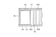
- FIG. 1 is a perspective view of a honeycomb panel according to a first embodiment of the present invention.
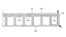
- Fig. 2 is a cross-sectional view of the honeycomb panel taken along line II-II in Fig. 1.
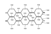
- Fig. 2 is a perspective view of a honeycomb core of the honeycomb panel shown in Fig. 1. It is the figure which looked at the honeycomb core in the direction of arrow IV of FIG.
- FIG. 2 is a diagram for explaining a bonding state between a honeycomb core and a first plate member in the honeycomb panel shown in FIG. 1.
- FIG. 4C is a cross-sectional view of the honeycomb core and the first plate member taken along the line CC of FIG. 4B. It is a figure explaining an example of the manufacturing method of the honeycomb panel shown in FIG.
- FIG. It is a figure explaining an example of the manufacturing method of the honeycomb panel shown in FIG. It is a figure explaining an example of the manufacturing method of the honeycomb panel shown in FIG. It is a figure explaining an example of the manufacturing method of the honeycomb panel shown in FIG. It is a figure explaining an example of the manufacturing method of the honeycomb panel shown in FIG. It is a figure explaining an example of the manufacturing method of the honeycomb panel shown in FIG. It is a figure explaining an example of the manufacturing method of the honeycomb panel shown in FIG. It is a perspective view of the honeycomb core of the honeycomb panel concerning the 2nd Embodiment of this invention. It is a figure which shows the housing
- FIG. 1 is a perspective view of the honeycomb panel 1 according to the first embodiment
- FIG. 2 is a cross-sectional view of the honeycomb panel 1 taken along the line II-II in FIG. 3 is a perspective view of the honeycomb core 10 of the honeycomb panel 1 shown in FIG. 1
- FIG. 4A is a view of the honeycomb core 10 viewed in the direction of arrow IV in FIG.
- a honeycomb panel 1 according to the present embodiment shown in FIGS. 1 and 2 includes a honeycomb core 10 having a front surface 10A and a back surface 10B, a first plate member 11 provided on the front surface 10A of the honeycomb core 10, and A second plate member 12 provided on the back surface 10B, a third plate member 13 provided on the surface of the first plate member 11, and a frame member 14 surrounding a side surface located between the front surface 10A and the back surface 10B of the honeycomb core 10; And a side plate 15 surrounding the frame member 14.
- Each component constituting the honeycomb core 10 is formed of a metal such as stainless steel or aluminum.
- each of these constituent members may be formed from a resin, a part thereof may be formed from a metal, and the other part may be formed from a resin.
- the honeycomb core 10 is a plate-like member that forms a honeycomb pattern by arranging a plurality of hexagonal cells 10S that are open on both sides of the front surface 10A and the back surface 10B. In this embodiment, the outer shape is rectangular. It has become.
- the honeycomb core 10 includes a plurality of core strips 100.
- the core strip 100 is a band-shaped member formed by alternately forming first trapezoidal portions 101 and second trapezoidal portions 102 that protrude in opposite directions.
- a reference line SL indicating a boundary between the first trapezoidal portion 101 and the second trapezoidal portion 102 is indicated by a two-dot chain line.
- the trapezoidal portion that protrudes from the reference line SL to the lower side in FIG. 4A is defined as the first trapezoidal portion 101, and is extended from the reference line SL to the upper side in FIG.
- the trapezoidal part to be taken out is defined as the second trapezoidal part 102.
- the plurality of core strips 100 are arranged such that the parallel directions of the trapezoidal portions 101 and 102 (the direction in which the trapezoidal portions 101 and 102 are arranged) are parallel to each other, and the opposite core strips 100 are opposite to each other.
- the top portions of the first trapezoidal portion 101 and the second trapezoidal portion 102 that protrude in the direction are abutted and joined.
- the honeycomb core 10 forms a honeycomb pattern composed of a plurality of hexagonal cells 10S opened on the front surface 10A and the back surface 10B.
- the tops of the first trapezoidal portion 101 and the second trapezoidal portion 102 are coupled to each other by spot welding, but these may be coupled by adhesion.
- the first trapezoidal portion 101 and the second trapezoidal portion 102 are more easily maintained in a higher temperature environment than in the case of an adhesive, the connection between the first trapezoidal portion 101 and the second trapezoidal portion 102 is easily maintained.
- spot welding it is preferable to employ spot welding.
- FIG. 3 shows a state where the surface 10A of the honeycomb core 10 covered with the first plate material 11 is viewed from above.
- FIG. 3 and FIG. 4A at the edge of the first trapezoidal portion 101 and the second trapezoidal portion 102 of at least some of the core strips 100 on the first plate member 11 side. Is provided with a first flange portion 111 projecting inside the cell 10S, and a second trapezoidal portion 101 and a second trapezoidal portion 102 of at least a part of the plurality of core strips 100.
- a second flange portion 112 is provided at the edge of the plate member 12 side so as to project inside the cell 10S.
- each first flange portion 111 is provided on the edge of the top portion 101A of the first trapezoidal portion 101 or the top portion 102A of the second trapezoidal portion 102 on the first plate member 11 side, and each second flange portion 111 is provided.
- the flange portion 112 is provided on the edge of the top portion 101A of the first trapezoidal portion 101 or the top portion 102A of the second trapezoidal portion 102 on the second plate member 12 side.
- the plurality of first flange portions 111 provided on the first plate member 11 side are formed so as to be located two inside one cell 10S with respect to some cells 10S, and are located inside one cell 10S.
- One of the two first flange portions 111 is provided at the edge of the first trapezoidal portion 101 of one core strip 100 forming the cell 10S in the adjacent core strip 100 on the first plate member 11 side
- the other of the two first flange portions 111 is provided at the edge on the first plate member 11 side of the second trapezoidal portion 102 of the other core strip 100 that forms the cell 10S in the adjacent core strip 100. Yes.
- the two first flange portions 111 positioned inside one cell 10S are in contact with each other in the direction orthogonal to the parallel direction of the trapezoidal portions 101 and 102. Further, as shown in FIG. 4, when two first flange portions 111 are positioned inside one cell 10S, the honeycomb core 10 is configured so that the second flange portion 112 is not positioned in the cell 10S. ing.
- the plurality of second flange portions 112 provided on the second plate member 12 side are also formed so as to be located two inside one cell 10S with respect to a part of the cells 10S, and inside one cell 10S.
- One of the two second flange portions 112 located on the second strip portion 112 is provided at the edge of the first trapezoidal portion 101 of one core strip 100 forming the cell 10S in the adjacent core strip 100 on the second plate 12 side.
- the other of the two second flange portions 112 is provided at the edge of the second trapezoidal portion 102 of the other core strip 100 forming the cell 10S in the adjacent core strip 100 on the second plate 12 side. It has been.
- the two second flange portions 112 positioned inside the one cell 10 ⁇ / b> S have their respective tips in a direction perpendicular to the parallel direction of the trapezoidal portions 101 and 102. It is in contact. Further, when two second flange portions 112 are positioned inside one cell 10S on the second plate material 12 side, the honeycomb core 10 does not position the first flange portion 111 on the first plate material 11 side of the cell 10S. It is configured as follows.
- two first flange portions 111 positioned inside one cell 10S are continuously provided in a direction orthogonal to the parallel direction of the trapezoidal portions 101 and 102.
- two second flange portions 112 located inside one cell 10S are continuously (repetitively) arranged in a direction orthogonal to the parallel direction of the trapezoidal portions 101 and 102. It has become so.
- the first flange portions 111 so that the two flange portions 112 are alternately arranged in the parallel direction when viewed in a plan view are arranged in a direction orthogonal to the parallel direction of the trapezoidal portions 101 and 102. And a second flange portion 112 are formed.
- the plan view means that the core strip 100 is viewed along the normal direction of the front and back surfaces 10A and 10B of the plate-like core strip 100.
- the rows continuously arranged in the direction orthogonal to the parallel direction of the trapezoidal portions 101 and 102 are as follows: The first flange portion 111 provided at the edge of the first trapezoidal portion 101 of the core strip 100 on the first plate member 11 side, and the second flange provided at the edge of the second trapezoidal portion 102 on the second plate member 12 side.
- Portions 112 are alternately formed in the parallel direction of the trapezoidal portions 101, 102 on the edge of the first trapezoidal portion 101 of the core strip 100 on the second plate member 12 side.
- the second flange portion 112 and the first flange portion 111 provided at the edge of the second trapezoidal portion 102 on the first plate member 11 side are alternately formed in the parallel direction of the trapezoidal portions 101 and 102.
- Two types of core strips 100 are required.
- Such two kinds of core strips 100 are in the other mode if one is inverted.
- Such a core strip 100 can be easily manufactured by forming by punching and bending the flange portions 111 and 112 after punching. Further, the thicknesses of the two types of core strips 100 may be different from each other. When one thickness is set to 1/5 to 1/2 of the other thickness, it may occur during welding. It becomes easy to suppress distortion of the core strip 100.
- the formation aspect of the 1st flange part 111 and the 2nd flange part 112 is not restricted to said aspect,
- one or more 1st flange parts 111 are located inside the same cell 10S, and one is provided.
- the 1st flange part 111 and the 2nd flange part 112 may be formed so that the above 2nd flange part 112 may be located.
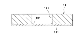
- FIG. 4B is a diagram for explaining a bonding state between the honeycomb core 10 and the first plate member 11 in the honeycomb panel 1, and is a view of the first plate member 11 viewed along the normal direction with respect to the plate surface of the first plate member 11.
- FIG. 4C is a cross-sectional view of the honeycomb core 10 and the first plate member 11 taken along the line CC of FIG. 4B.
- the first plate member 11 has one or more (in this example, a plurality) through holes 121 that overlap one or more (in this example, a plurality of) first flange portions 111.
- the first plate member 11 is bonded to the honeycomb core 10 by welding the outer surface of the first flange portion 111 facing the outside through the through hole 121 and the inner peripheral surface of the through hole 121.
- One through-hole 121 is provided for one first flange portion 111, and the first plate member 11 and the honeycomb core 10 are joined at two locations in one cell 10S.
- the shape of the through hole 121 is circular, but may be other shapes such as a rectangular shape.
- the outer surface of the first flange portion 111 and the inner peripheral surface of the through hole 121 are arc welded, and the weld metal portion 131 is between the outer surface of the first flange portion 111 and the inner peripheral surface of the through hole 121.
- the arc welding is performed by accessing the boundary between the through hole 121 and the first flange portion 111 from the outside of the through hole 121, the outer surface of the first flange portion 111 and the inner peripheral surface of the through hole 121 are easily welded. It becomes possible to do.
- the type of arc welding is not particularly limited, and various methods such as TIG welding and argon welding can be used.
- the welding of the outer surface of the first flange portion 111 and the inner peripheral surface of the through hole 121 is not limited to arc welding, and may be performed by electric resistance welding or brazing.
- the outer surface of the first flange portion 111 and the inner peripheral surface of the through hole 121 are coupled by welding, but these may be coupled by bonding with an adhesive. Moreover, when the 1st flange part 111 and the 1st board
- the second plate member 12 has a plurality of surface contact regions 122 (see FIGS. 3 and 4A) that are in surface contact with the outer surface of the plurality of second flange portions 112 facing the second plate member 12, and the second flange portion 112.
- the outer surface and the surface contact area 122 are welded to bond to the honeycomb core 10.
- the two second flange portions 112 are positioned in one cell 10S, so that the second plate member 12 and the honeycomb core 10 are joined at two locations in one cell 10S.
- plate material 12 is comprised as a non-opening board
- the second plate 12 is bonded to the honeycomb core 10 by spot welding of the outer surface of the second flange portion 112 and the surface contact region 122 of the second plate 12, and the reference numerals in FIG. 4A Reference numeral 132 denotes a spot welding mark.
- the second plate 12 is bonded to the honeycomb core 10 before the first plate 11.
- the open portion on the front surface 10A side is the first flange portion 111. Not covered by.
- the outer surface of the second flange portion 112 and the surface contact region 122 of the second plate member 12 are coupled by welding, but these may be coupled by bonding with an adhesive. Moreover, when the 2nd flange part 112 and the 2nd board
- the frame member 14 surrounds the side surface of the honeycomb core 10 and is positioned between the first plate member 11 and the second plate member 12.
- the frame member 14 is joined to the honeycomb core 10, the first plate member 11, and the second plate member 12 by welding.
- the side plate 15 surrounds the side surface of the frame member 14.
- the second plate member 12 projects laterally outward from the frame member 14, and the side plate 15 is placed on this projecting portion.
- the first plate 11 does not protrude from the frame member 14.
- the side plate 15 placed on the second plate 12 projects from the frame member 14 and the first plate 11.
- the side plate 15 is coupled to the second plate member 12, the frame member 14, and the first plate member 11 by welding.
- the third plate member 13 is disposed so as to be fitted inside the side plate 15 protruding from the first plate member 11 and is welded to the side plate 15 to close the first plate member 11.
- FIG. 5 is a view of the core strip 100 viewed along the normal direction with respect to the front and back surfaces 10A and 10B of the honeycomb core 10.
- FIGS. 6 to 9 are normal directions with respect to the front and back surfaces 10A and 10B of the honeycomb core 10.
- FIG. 3 is a schematic cross-sectional view when a proper place of the honeycomb core 10 is cut along a plane parallel to the surface.
- a plurality of core strips 100 are prepared.
- Each core strip 100 is arranged so that the parallel directions of the trapezoidal portions 101 and 102 are parallel to each other.
- the first trapezoidal portion 101 and the first trapezoidal portions 101 project in opposite directions between the adjacent core strips 100.
- the tops of the two trapezoidal portions 102 are butted together and then joined.
- the tops are joined by spot welding.
- the honeycomb core 10 which forms the honeycomb pattern which consists of a plurality of hexagonal cells opened on the front surface 10A and the back surface 10B is formed.
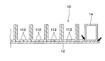
- the second plate 12 and the back surface 10 ⁇ / b> B of the honeycomb core 10 are overlapped and bonded together.
- the second plate member 12 and the honeycomb core 10 are joined by spot welding the outer surface of the second flange portion 112 and the surface contact region 122 of the second plate member 12.
- the open portion on the surface 10A side is not covered by the first flange portion 111, so the electrode E1 is inserted inside the cell 10S, The electrode E1 can be easily brought into contact with the second flange portion 112.
- the second flange portion 112 and the second plate member 12 are sandwiched between the electrode E1 and the electrode E2 disposed to face the electrode E1, and a current flows.
- plate material 12 and the honeycomb core 10 are couple
- the frame member 14 is joined to the honeycomb core 10 and the second plate member 12 by welding.
- the arrow in FIG. 7 has shown the welding location of the frame member 14 and its peripheral member.
- the frame member 14 and its peripheral members are welded by arc welding, but electric resistance welding may be employed instead of arc welding.
- the first plate member 11 and the surface 10 ⁇ / b> A of the honeycomb core 10 are overlapped and bonded together.
- the first plate member 11 has a plurality of through holes 121 that overlap with the plurality of first flange portions 111, and the plurality of through holes 121 overlap the plurality of first flange portions 111 of the honeycomb core 10 with respect to the honeycomb core 10.
- plate material 11 and the honeycomb core 10 are couple
- the outer surface of the first flange portion 111 and the inner peripheral surface of the through hole 121 are arc welded. Since the arc welding is performed by accessing the boundary between the through hole 121 and the first flange portion 111 from the outside of the through hole 121, the arc welding can be easily performed.
- the side plate 15 is bonded around the honeycomb core 10, and the third plate material 13 is disposed on the first plate material 11 and bonded.
- the arrow in FIG. 9 has shown the welding location of the side plate 15 or the 3rd board
- the side plate 15 and the third plate member 13 and the peripheral members are welded by arc welding, but electric resistance welding may be employed instead of arc welding.
- the first plate member 11 has a plurality of through holes 121 that overlap with the plurality of first flange portions 111 provided in the honeycomb core 10, and the external through the through holes 121.
- the first plate member 11 and the honeycomb core 10 are bonded to each other by welding the outer surface of the first flange portion 111 facing the side and the inner peripheral surface of the through hole 121.
- the outer surface of the first flange portion 111 and the inner peripheral surface of the through hole 121 of the first plate member 11 are arc-welded, and a weld metal portion is provided between the outer surface of the first flange portion 111 and the inner peripheral surface of the through hole 121. 131 is provided.
- the honeycomb panel 1 with high reliability.
- the second plate member 12 has a plurality of surface contact regions 122 that are in surface contact with the outer surface of the plurality of second flange portions 112 provided on the honeycomb core 10 and facing the second plate member 12 side.
- the outer surface and the surface contact region 122 are welded to be coupled to the honeycomb core 10.
- plate material 12 is a structure couple
- the outer surface of the second flange portion 112 and the surface contact region 122 are spot-welded, generation of metal oxide can be suppressed as compared with the case of arc welding, resulting from such metal oxide. Generation of gas can be suppressed.
- the honeycomb panel 1 is used as a part of the wall portion of the casing that is hermetically sealed, the generation of gas due to the metal oxide inside the casing may not be desirable. Spot welding is particularly useful.
- two second flange portions 112 are located inside each of at least some of the cells 10S of the plurality of cells 10S in the honeycomb panel 1, and the second plate member 12 is The second flange portion 112 is coupled to the inside of the cell 10S.
- the coupling strength can be improved.
- the honeycomb core 10 does not place the first flange portion 111 inside the cell 10S. Therefore, since a member for welding such as the electrode E1 can be inserted into the cell 10S and can be easily brought into contact with the second flange portion 112, the manufacturing efficiency of the honeycomb panel 1 can be improved.
- first flange portions 111 when two first flange portions 111 are positioned inside one cell 10S, the two first flange portions 111 are in contact with each other at their tips. Even when two second flange portions 112 are positioned inside one cell 10S, the two second flange portions 112 are in contact with each other at their tips.
- FIGS. 11A to 11C are views showing a housing in which a honeycomb panel according to each embodiment of the present invention can be installed.
- a honeycomb panel according to each embodiment includes a casing 201 having a rectangular wall section as shown in FIG. 11A, a casing 202 having a circular wall section as shown in FIG. 11B, Alternatively, the cross section of the wall portion as shown in FIG. 11C may be applied to the case 203 having a racetrack shape having a pair of curved portions and a pair of straight portions, and may constitute at least a part of the wall portion.
- the casings 201 to 203 as described above are casings in which the inside of a vacuum deposition chamber or the like is at a high temperature and in a vacuum state, for example, the second plate member 12 is directed to the inner side, and the first plate member 11 is placed.
- the wall portion of the housing is constituted by the honeycomb panel toward the outside.
- the second plate 12 is sucked in vacuum by being coupled with the two second flange portions 112 per cell 10S, for example, while maintaining suitable airtightness with the honeycomb core 10.
- the first plate member 11 has the through-hole 121, since it is easily and firmly coupled to the first plate member 11, the manufacturing efficiency of the honeycomb panel is sufficiently satisfied while satisfying the specifications required on the side not exposed to vacuum. Can be improved and the cost can be reduced.
- the honeycomb panel according to the present embodiment when the honeycomb panel according to the present embodiment is applied to a casing, not only the weight reduction is realized, but also the specifications desired for the casing are sufficiently satisfied, and the manufacturing efficiency of the casing is improved.
- the cost can be reduced, various advantages can be obtained in the housing.
- the housing is not particularly limited.
- the honeycomb panel according to the present embodiment can be usefully used as a wall portion of a train, an automobile, an aircraft, a rocket, a shelter, or the like.
- the first flange portion 111 and the second flange portion 112 are provided at the top of the trapezoidal portion of the core strip 100. Instead, both of the pair of side portions of the trapezoidal portion are provided. Or the 1st flange part 111 or the 2nd flange part 112 may be provided in either.
Landscapes
- Engineering & Computer Science (AREA)
- Mechanical Engineering (AREA)
- Physics & Mathematics (AREA)
- Plasma & Fusion (AREA)
- Laminated Bodies (AREA)
- Butt Welding And Welding Of Specific Article (AREA)
Abstract
L'invention concerne un panneau 1 en nid d'abeilles comportant: un cœur 10 en nid d'abeilles présentant une surface 10A et une surface arrière 10B; et un premier élément 11 de plaque placé sur la surface 10A du cœur 10 en nid d'abeilles, une première partie 111 de voile qui dépasse jusqu'à l'intérieur de cellules 10S étant placée au niveau de bordures d'extrémités du côté premier élément 11 de plaque de parties trapézoïdales 101 et 102 d'une pluralité de bandes 100 de cœur formant le cœur 10 en nid d'abeilles. Le premier élément 11 de plaque présente un trou 121 de pénétration chevauchant la première partie 111 de voile et est lié au cœur 10 en nid d'abeilles lorsqu'une surface extérieure de la première partie 111 de voile orientée vers l'extérieur à travers le trou 121 de pénétration et une surface périphérique intérieure du trou 121 de pénétration sont soudées l'une à l'autre.
Priority Applications (3)
| Application Number | Priority Date | Filing Date | Title |
|---|---|---|---|
| US16/968,688 US20200398519A1 (en) | 2018-03-05 | 2019-03-01 | Honeycomb panel, manufacturing method thereof, and housing |
| KR1020207022894A KR102721399B1 (ko) | 2018-03-05 | 2019-03-01 | 허니콤 패널 및 그 제조 방법, 그리고 하우징 |
| CN201980017120.3A CN111819073B (zh) | 2018-03-05 | 2019-03-01 | 蜂窝板及其制造方法、以及外壳 |
Applications Claiming Priority (2)
| Application Number | Priority Date | Filing Date | Title |
|---|---|---|---|
| JP2018038873A JP6976572B2 (ja) | 2018-03-05 | 2018-03-05 | ハニカムパネル及びその製造方法、並びに筐体 |
| JP2018-038873 | 2018-03-05 |
Publications (1)
| Publication Number | Publication Date |
|---|---|
| WO2019172128A1 true WO2019172128A1 (fr) | 2019-09-12 |
Family
ID=67846068
Family Applications (1)
| Application Number | Title | Priority Date | Filing Date |
|---|---|---|---|
| PCT/JP2019/008143 Ceased WO2019172128A1 (fr) | 2018-03-05 | 2019-03-01 | Panneau en nid d'abeilles et son procédé de fabrication, et boîtier |
Country Status (6)
| Country | Link |
|---|---|
| US (1) | US20200398519A1 (fr) |
| JP (1) | JP6976572B2 (fr) |
| KR (1) | KR102721399B1 (fr) |
| CN (1) | CN111819073B (fr) |
| TW (1) | TWI787474B (fr) |
| WO (1) | WO2019172128A1 (fr) |
Families Citing this family (8)
| Publication number | Priority date | Publication date | Assignee | Title |
|---|---|---|---|---|
| FR3036307B1 (fr) * | 2015-05-22 | 2017-06-02 | Halcyon | Procede ameliore de fabrication d'une piece metallique du type sandwich presentant une forme non-developpable |
| CN111649221B (zh) * | 2020-05-25 | 2023-08-01 | 湖南省冶金材料研究院有限公司 | 一种内嵌式纬向增强型金属蜂窝结构及其制作方法 |
| CN113895098B (zh) * | 2020-06-22 | 2023-08-29 | 中国航发商用航空发动机有限责任公司 | 声衬件、制造方法、动力推进系统以及蜂窝芯 |
| CN113182630A (zh) * | 2021-03-30 | 2021-07-30 | 厦门美乐镁装饰材料有限公司 | 一种铝复合蜂窝板的焊接工艺 |
| CN113478083B (zh) * | 2021-07-23 | 2023-03-14 | 马鞍山安达泰克科技有限公司 | 蜂窝芯材 |
| KR20240121847A (ko) * | 2022-12-02 | 2024-08-09 | 원텍 오토메이션 테크놀러지 코., 엘티디. | 허니컴 충격방지 종이패드 구조, 가공 방법 및 가공 기기 |
| CN116638132A (zh) * | 2023-06-12 | 2023-08-25 | 成都飞机工业(集团)有限责任公司 | 一种蜂窝芯翻面加工防错位补偿方法 |
| CN117900347B (zh) * | 2024-03-15 | 2024-05-24 | 常州弘建新材料有限公司 | 一种蜂窝铝板边角压型设备 |
Citations (8)
| Publication number | Priority date | Publication date | Assignee | Title |
|---|---|---|---|---|
| JPS6094343A (ja) * | 1983-10-28 | 1985-05-27 | テ−ア−ルイ−・コ−ポレ−シヨン | ハニカムコアパネル用のコアストリツプ及びその製造方法 |
| JPS60227971A (ja) * | 1984-01-31 | 1985-11-13 | Honda Motor Co Ltd | 自動ア−ク溶接方式 |
| JPH01130939A (ja) * | 1987-10-27 | 1989-05-23 | Avco Corp | ハニカム構造組立体 |
| JPH03294032A (ja) * | 1990-04-13 | 1991-12-25 | Nippon Steel Corp | ハニカムコアパネル用のコアストリップおよびハニカムパネルの製造方法 |
| JPH0531589A (ja) * | 1991-07-30 | 1993-02-09 | Nippon Steel Corp | ハニカムパネル及びハニカムパネルの製造方法 |
| JPH06206270A (ja) * | 1993-01-12 | 1994-07-26 | Showa Aircraft Ind Co Ltd | ハニカムパネルおよびその製造方法 |
| JPH06316009A (ja) * | 1991-07-30 | 1994-11-15 | Nippon Steel Corp | ハニカムパネル及びハニカムパネルの製造方法 |
| JPH0768677A (ja) * | 1993-09-07 | 1995-03-14 | Sumitomo Light Metal Ind Ltd | ろう付けハニカムパネルおよびその製造方法 |
Family Cites Families (10)
| Publication number | Priority date | Publication date | Assignee | Title |
|---|---|---|---|---|
| US4161231A (en) * | 1973-10-31 | 1979-07-17 | Rolls-Royce Limited | Metal cavitated sandwich structures |
| KR100756629B1 (ko) * | 2007-02-27 | 2007-09-07 | 문광선 | 하니콤 코아 및 이를 이용한 샌드위치패널 |
| CN101032876A (zh) * | 2007-04-10 | 2007-09-12 | 南京工业大学 | 点阵增强型复合材料夹层结构 |
| CN201835400U (zh) * | 2010-09-30 | 2011-05-18 | 广东杭萧钢构有限公司 | 一种混凝土钢板剪力墙 |
| CN103437545A (zh) * | 2013-09-09 | 2013-12-11 | 姜立平 | 一种新型复合建筑模板及其制造方法 |
| CN103786372A (zh) * | 2014-03-03 | 2014-05-14 | 江苏德兴数码科技有限公司 | 铝蜂窝吸气平台及生产方法 |
| BR112016020808B1 (pt) * | 2014-03-12 | 2022-09-27 | Tres S.R.L. | Elemento polimérico de absorção de choque para um veículo, membro lateral longitudinal e veículo |
| GB2550966A (en) * | 2016-06-03 | 2017-12-06 | The Welding Inst | Joining method using in-situ formed fasteners |
| JP6782580B2 (ja) * | 2016-08-04 | 2020-11-11 | 株式会社神戸製鋼所 | アークスポット溶接方法 |
| JP2018034166A (ja) * | 2016-08-29 | 2018-03-08 | 株式会社神戸製鋼所 | 異材接合用アークスポット溶接法、接合補助部材、及び、異材溶接継手 |
-
2018
- 2018-03-05 JP JP2018038873A patent/JP6976572B2/ja active Active
-
2019
- 2019-03-01 WO PCT/JP2019/008143 patent/WO2019172128A1/fr not_active Ceased
- 2019-03-01 US US16/968,688 patent/US20200398519A1/en not_active Abandoned
- 2019-03-01 KR KR1020207022894A patent/KR102721399B1/ko active Active
- 2019-03-01 CN CN201980017120.3A patent/CN111819073B/zh not_active Expired - Fee Related
- 2019-03-05 TW TW108107172A patent/TWI787474B/zh not_active IP Right Cessation
Patent Citations (8)
| Publication number | Priority date | Publication date | Assignee | Title |
|---|---|---|---|---|
| JPS6094343A (ja) * | 1983-10-28 | 1985-05-27 | テ−ア−ルイ−・コ−ポレ−シヨン | ハニカムコアパネル用のコアストリツプ及びその製造方法 |
| JPS60227971A (ja) * | 1984-01-31 | 1985-11-13 | Honda Motor Co Ltd | 自動ア−ク溶接方式 |
| JPH01130939A (ja) * | 1987-10-27 | 1989-05-23 | Avco Corp | ハニカム構造組立体 |
| JPH03294032A (ja) * | 1990-04-13 | 1991-12-25 | Nippon Steel Corp | ハニカムコアパネル用のコアストリップおよびハニカムパネルの製造方法 |
| JPH0531589A (ja) * | 1991-07-30 | 1993-02-09 | Nippon Steel Corp | ハニカムパネル及びハニカムパネルの製造方法 |
| JPH06316009A (ja) * | 1991-07-30 | 1994-11-15 | Nippon Steel Corp | ハニカムパネル及びハニカムパネルの製造方法 |
| JPH06206270A (ja) * | 1993-01-12 | 1994-07-26 | Showa Aircraft Ind Co Ltd | ハニカムパネルおよびその製造方法 |
| JPH0768677A (ja) * | 1993-09-07 | 1995-03-14 | Sumitomo Light Metal Ind Ltd | ろう付けハニカムパネルおよびその製造方法 |
Also Published As
| Publication number | Publication date |
|---|---|
| CN111819073A (zh) | 2020-10-23 |
| TW201938358A (zh) | 2019-10-01 |
| CN111819073B (zh) | 2022-12-20 |
| KR102721399B1 (ko) | 2024-10-25 |
| KR20200127991A (ko) | 2020-11-11 |
| JP6976572B2 (ja) | 2021-12-08 |
| US20200398519A1 (en) | 2020-12-24 |
| JP2019151047A (ja) | 2019-09-12 |
| TWI787474B (zh) | 2022-12-21 |
Similar Documents
| Publication | Publication Date | Title |
|---|---|---|
| WO2019172128A1 (fr) | Panneau en nid d'abeilles et son procédé de fabrication, et boîtier | |
| JP6183555B2 (ja) | 組電池のタブ溶接方法 | |
| JP5237355B2 (ja) | パネル構造体の製造方法 | |
| JP2011211195A (ja) | 冷却板アセンブリ、および冷却板アセンブリの製造方法 | |
| US10598440B2 (en) | Method of manufacturing heat exchanger | |
| TWI680551B (zh) | 蒸氣室 | |
| JP2007092999A (ja) | 2枚の金属シートの間に挿入された樹脂層から成る2枚のラミネートされたパネルの間の組立装置 | |
| JP4829172B2 (ja) | 真空断熱パネル | |
| JP2009064734A (ja) | 燃料電池用金属セパレータ、燃料電池スタック、および燃料電池用金属セパレータの製造方法 | |
| JPH071061A (ja) | ハニカムパネルの製造方法 | |
| JP2014202236A (ja) | 真空断熱パネル | |
| JP3586411B2 (ja) | 放射線源格納装置 | |
| JP7548961B2 (ja) | 接合体の製造方法 | |
| JPH06316009A (ja) | ハニカムパネル及びハニカムパネルの製造方法 | |
| JPH08126290A (ja) | ヨークの接合方法 | |
| JP6033728B2 (ja) | 保持部材 | |
| JP5941837B2 (ja) | 鉄道車両構体、鉄道車両構体の製造方法 | |
| JP3750432B2 (ja) | セラミック板と金属製ケースの気密接合方法 | |
| US20210262422A1 (en) | Heat exchanger housing and method of manufacturing a heat exchanger | |
| JP2025187149A (ja) | 二次電池および二次電池の製造方法 | |
| JP2024104418A (ja) | 冷却構造体、及びバッテリーケース | |
| CN116053693A (zh) | 电动车辆二次电池用盖板焊接构件 | |
| JP2009214140A (ja) | 中空パネルおよびその製造方法、パネル構造体 | |
| JP2012016741A (ja) | レーザ隅肉溶接方法 | |
| JPH0982531A (ja) | 電気機器用タンク及びその製造方法 |
Legal Events
| Date | Code | Title | Description |
|---|---|---|---|
| 121 | Ep: the epo has been informed by wipo that ep was designated in this application |
Ref document number: 19764285 Country of ref document: EP Kind code of ref document: A1 |
|
| NENP | Non-entry into the national phase |
Ref country code: DE |
|
| 122 | Ep: pct application non-entry in european phase |
Ref document number: 19764285 Country of ref document: EP Kind code of ref document: A1 |