WO2020004088A1 - Dispositif de perfusion et procédé de perfusion - Google Patents
Dispositif de perfusion et procédé de perfusion Download PDFInfo
- Publication number
- WO2020004088A1 WO2020004088A1 PCT/JP2019/023752 JP2019023752W WO2020004088A1 WO 2020004088 A1 WO2020004088 A1 WO 2020004088A1 JP 2019023752 W JP2019023752 W JP 2019023752W WO 2020004088 A1 WO2020004088 A1 WO 2020004088A1
- Authority
- WO
- WIPO (PCT)
- Prior art keywords
- perfusion
- organ
- perfusate
- pump
- kidney
- Prior art date
- Legal status (The legal status is an assumption and is not a legal conclusion. Google has not performed a legal analysis and makes no representation as to the accuracy of the status listed.)
- Ceased
Links
Images



Classifications
-
- A—HUMAN NECESSITIES
- A01—AGRICULTURE; FORESTRY; ANIMAL HUSBANDRY; HUNTING; TRAPPING; FISHING
- A01N—PRESERVATION OF BODIES OF HUMANS OR ANIMALS OR PLANTS OR PARTS THEREOF; BIOCIDES, e.g. AS DISINFECTANTS, AS PESTICIDES OR AS HERBICIDES; PEST REPELLANTS OR ATTRACTANTS; PLANT GROWTH REGULATORS
- A01N1/00—Preservation of bodies of humans or animals, or parts thereof
- A01N1/10—Preservation of living parts
-
- F—MECHANICAL ENGINEERING; LIGHTING; HEATING; WEAPONS; BLASTING
- F04—POSITIVE - DISPLACEMENT MACHINES FOR LIQUIDS; PUMPS FOR LIQUIDS OR ELASTIC FLUIDS
- F04B—POSITIVE-DISPLACEMENT MACHINES FOR LIQUIDS; PUMPS
- F04B49/00—Control, e.g. of pump delivery, or pump pressure of, or safety measures for, machines, pumps, or pumping installations, not otherwise provided for, or of interest apart from, groups F04B1/00 - F04B47/00
- F04B49/08—Regulating by delivery pressure
Definitions
- the present invention relates to a perfusion apparatus and a perfusion method for preserving an organ by perfusion.
- various preservation methods and perfusion methods have been developed in order to preserve the removed organ in a transplantable state.
- a simple cooling method in which blood in the organ is replaced with a low-temperature organ preservation solution in order to suppress cell metabolism and then immersed in a low-temperature preservation solution is known.
- a perfusion preservation method is known in which an organ preservation solution is perfused into an intravascular vascular network for the purpose of removing waste products from a stored organ.
- Patent Document 1 A conventional perfusion apparatus for preserving an organ by perfusion is described in, for example, Patent Document 1.
- a perfusion solution sent from a reservoir to a roller pump through a glass oxygenator is perfused into the liver via a cannula after oxygenation and removal of an air embolus.
- Patent Document 1 Conventionally, as described in Patent Document 1, various devices have been devised in order to preserve an organ to be perfused in a better condition.
- the state of the removed organ is significantly different between the case where the removal is performed from the living body and the case where the removal is performed after the death of the donor.
- the state of the organ also differs depending on the state of the donor and the state at the time of extraction.
- the present invention has been made in view of such circumstances, and has as its object to provide a technique for preserving an extracted organ in a better state.
- a first invention of the present application is a perfusion apparatus for perfusing an organ with a perfusion solution, comprising a reservoir for storing the perfusion solution, and an inflow for flowing the perfusion solution from the reservoir to the organ.
- a pressure measurement unit that measures pressure
- a control unit that controls the pumping amount of the pump, wherein the control unit controls the pump so that the measurement value of the pressure measurement unit does not exceed a predetermined threshold. Feedback control is performed for this.
- a second invention of the present application is the perfusion apparatus according to the first invention, wherein the threshold value is 130 mmHg or less.
- 3A third invention of the present application is the perfusion apparatus according to the first invention, wherein the threshold value is 100 mmHg or less.
- 4A fourth invention of the present application is the perfusion apparatus according to the first invention, wherein the control unit sets a pumping amount of the pump to be equal to or less than an average blood flow supplied to the organ in a healthy body.
- 5A fifth invention of the present application is the perfusion apparatus according to the first invention, wherein the target organ is a kidney, and the control unit controls the pump to deliver a fluid of 8 ml or less per minute.
- the sixth invention of the present application is the perfusion apparatus according to the first invention or the fifth invention, wherein the target organ is a kidney, and the threshold value is 100 mmHg or less.
- a seventh invention of the present application is the perfusion apparatus according to the first invention, comprising the two inflow pipes, wherein the target organ is a liver, and one of the inflow pipes is connected to a portal vein of the liver.
- the other of the inflow pipes is connected to the hepatic artery of the liver, the threshold value in the inflow pipe connected to the portal vein is 40 mmHg or less, and the threshold value in the inflow pipe connected to the hepatic artery is Is 500 mmHg or less.
- An eighth invention of the present application is a perfusion method for perfusing an organ with a perfusion solution, comprising the steps of: a) measuring the pressure of the perfusion solution at the most downstream side in an inflow pipe for flowing the perfusion solution into the organ; b) performing a feedback control of a pump that sends the perfusate in the inflow pipe so that the measured value in the step a) does not exceed a predetermined threshold.
- the organ it is possible to prevent the organ from being damaged by the inflow of the perfusate. Therefore, the removed organ can be preserved in a better state.
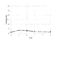
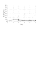
- FIG. 3 is a diagram showing the time course of kidney urea nitrogen concentration in an experiment. It is a figure showing time course of the creatinine concentration of the kidney in an experiment.
- FIG. 3 is a diagram showing the time course of kidney urea nitrogen concentration in an experiment.
- FIG. 3 is a diagram showing the time course of kidney urea nitrogen concentration in an experiment. It is the schematic which showed the structure of the perfusion apparatus which concerns on 2nd Embodiment.
- “donor” and “recipient” may be a human or a non-human animal. That is, in the present application, the “organ” including “kidney” and “liver” may be a human organ or a non-human animal organ.
- the non-human animal may be a rodent including a mouse and a rat, an ungulate including a pig, a goat and a sheep, a non-human primate including a chimpanzee, and other non-human mammals. Other animals may be used.
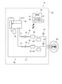
- FIG. 1 is a schematic diagram showing a configuration of the perfusion apparatus 1.
- the perfusion device 1 is a device for temporarily storing an organ such as a kidney extracted from a donor outside the body until it is transplanted to a recipient.
- the perfusion apparatus 1 includes a housing 20, a reservoir 30, a perfusate inlet 40, a perfusate outlet 50, and a controller 60.
- the perfusion apparatus 1 is an apparatus for performing a perfusion process on an extracted organ.
- the organ to be perfused is the kidney 9.
- the organ to be perfused may be a liver or another organ.
- the housing 20 houses the reservoir 30, the perfusate inflow section 40 excluding a part of the inflow pipe 41, and the perfusion fluid discharge section 50 excluding a part of the discharge pipe 51.
- the reservoir 30 is a container for storing a perfusate.
- a temperature control mechanism 31 and a gas exchange mechanism 32 are provided around the reservoir 30.
- the temperature adjusting mechanism 31 adjusts the temperature of the perfusate stored in the reservoir 30.
- the gas exchange mechanism 32 supplies gas such as oxygen to the perfusion solution stored in the reservoir 30 to dissolve the gas in the perfusion solution.
- the gas exchange mechanism 32 may be inserted into an inflow pipe 41 of the perfusate inflow section 40, which will be described later.
- An ETK solution is used as the perfusion solution of the present embodiment. Note that other types of perfusate may be used as the perfusate.
- the perfusate inlet 40 supplies the perfusate from the reservoir 30 to the kidney 9.
- the perfusate inflow section 40 includes an inflow pipe 41, a pump 42, a temperature adjustment unit 43, a deaeration unit 44, and a pressure gauge 45.
- the pump 42, the temperature adjustment unit 43, the deaeration unit 44, and the pressure gauge 45 are inserted into the inflow pipe 41.
- the perfusate inflow section 40 is disposed inside the housing 20 except for a part of the inflow pipe 41.
- One end of the inflow pipe 41 is connected to the reservoir 30.
- the other end of the inflow pipe 41 is connected to an organ to be perfused during the perfusion process.
- the other end of the inflow pipe 41 is connected to the renal artery of the kidney 9.
- the perfusate is supplied from the reservoir 30 to the renal artery of the kidney 9 via the inflow pipe 41.
- the pump 42 generates a flow of the perfusate flowing from the reservoir 30 to the kidney 9 in the inflow pipe 41.
- the pump 42 of the present embodiment is a pump equipped with a brushless motor. As a result, it is possible to stably control the amount of perfusate to be sent in units of 1 ml / min.
- the temperature adjusting unit 43 adjusts the temperature of the perfusate in the inflow pipe 41.
- the temperature adjusting unit 43 immerses a part of the inflow pipe 41 in a liquid having a set temperature of, for example, 4 ° C., 20 ° C., or 37 ° C., so that the perfusate in the inflow pipe 41 is set to the set temperature. adjust.
- the deaeration unit 44 removes gas components of the perfusate in the inflow pipe 41.
- the pressure gauge 45 is disposed downstream of the pump 42, the temperature adjustment unit 43, and the deaeration unit 44 inserted in the inflow pipe 41. That is, the pressure gauge 45 is arranged on the most downstream side of the inflow pipe 41. That is, the pressure gauge 45 is a pressure measuring unit that measures the pressure of the perfusate at the most downstream side in the inflow pipe 41. Thereby, the pressure of the perfusate can be measured at the site closest to the kidney 9 to be perfused in the inflow pipe 41.
- the perfusate discharging unit 50 discharges the perfusate from the kidney 9.
- the perfusate discharge section 50 has a discharge pipe 51.
- One end of the discharge pipe 51 is connected to an organ to be perfused during the perfusion process.
- one end of the discharge pipe 51 is connected to a renal vein of the kidney 9.
- the other end of the discharge pipe 51 is connected to the reservoir 30.
- a pump for generating a flow of the perfusate flowing from the kidney 9 toward the reservoir 30 may be inserted in the discharge pipe 51.
- the perfusion apparatus 1 of the present embodiment has a configuration in which the perfusate discharged from the kidney 9 is returned to the reservoir 30, but the present invention is not limited to this.
- the perfusate discharged from the kidney 9 may be discarded or stored in another container without being returned to the reservoir 30.
- the reservoir 30, the perfusate inflow section 40, or the perfusion solution discharge section 50 may include a measurement unit for detecting pH or a specific component.
- the perfusate inlet 40 and the perfusate outlet 50 may include a flow meter for measuring the flow rate of the perfusate.
- an electromagnetic valve for controlling communication may be interposed in the inflow pipe 41 and the discharge pipe 51.
- the control unit 60 is a part for controlling the operation of each unit in the perfusion apparatus 1.
- the control unit 60 of the present embodiment is configured by a computer having an arithmetic processing unit 61 such as a CPU, a memory 62 such as a RAM, and a storage unit 63 such as a hard disk drive. ing.
- the control unit 60 is electrically connected to the temperature adjustment mechanism 31, the gas exchange mechanism 32, the pump 42, the temperature adjustment unit 43, the deaeration unit 44, and the pressure gauge 45, respectively.
- the control unit 60 controls the amount of liquid sent from the pump 42. Specifically, the control unit 60 controls the amount of liquid sent from the pump 42 by performing feedback control so that the measured value of the pressure gauge 45 does not exceed a predetermined threshold.
- the perfusion apparatus 1 may be used for performing a perfusion process while performing an operation of removing and transplanting an organ.
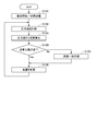
- FIG. 2 is a flowchart showing a flow of a perfusion process of the kidney 9 using the perfusion apparatus 1.
- FIG. 3 is a diagram illustrating a schematic example of a time lapse between a liquid supply amount of the pump 42 and a pressure value measured by the pressure gauge 45 in the perfusion process.
- a kidney 9 referred to as a “first kidney” that has been removed and started perfusion after cardiac arrest is indicated by a solid line, and a kidney 9 (“second kidney”) whose perfusion started immediately after removal from a healthy living body. ) Is indicated by a dashed line.
- the threshold value of the pressure of the perfusate at the most downstream side of the inflow pipe 41 is set to 100 mmHg. Further, the maximum value of the amount of perfusate delivered to the renal artery of the kidney 9 is set to 8 ml / min.
- the control unit 60 operates the pump 42 so that the pumping amount gradually increases from 0 ml / min.
- the pumping amount (initial flow rate) of the pump 42 at the start of perfusion is, for example, 1 ml / min or 2 ml / min, which is sufficiently smaller than the maximum value of 8 ml / min, instead of 0 ml / min. It may be. It is preferable that the pumping amount of the pump 42 at the start of perfusion be sufficiently smaller than the maximum value of the pumping amount.
- control unit 60 After the start of perfusion in step S101, the control unit 60 causes the pressure gauge 45 to measure the pressure of the perfusate at the most downstream side in the inflow pipe 41 (step S102). Then, the control unit 60 starts monitoring the pressure value measured by the pressure gauge 45.
- control unit 60 performs feedback control on the pump 42 so that the pressure value, which is the measurement value of the pressure gauge 45, does not exceed the threshold value (100 mmHg), and the liquid supply amount of the pump 42 gradually increases. Is calculated (step S103).
- the calculation of the liquid sending amount in step S103 may be based on proportional control, or may be based on other feedback control such as PI control or PID control.
- control unit 60 determines whether or not the amount of the pump 42 calculated in step S103 is equal to or less than the maximum value (8 ml / min) (step S104). If the control unit 60 determines that the pumping amount of the pump 42 calculated in step S103 is equal to or less than the maximum value (8 ml / min), the control unit 60 proceeds to step S106, and determines the pumping amount of the pump 42 in step S103. It changes so that it may become the calculated liquid sending (step S106).
- step S104 if it is determined in step S104 that the pumping amount of the pump 42 calculated in step S103 is larger than the maximum value (8 ml / min), the pumping amount of the pump 42 is determined to the maximum value (8 ml / min) (step S104). S105). Then, the control unit 60 proceeds to step S106, and changes the liquid supply amount of the pump 42 to the maximum value (8 ml / min) determined in step S105 (step S106).
- step S106 Updating the liquid supply amount of the pump 42 in step S106, the control unit 60 returns to step S102 and continues the feedback control.
- This perfusion apparatus 1 performs a perfusion process by connecting the inflow pipe 41 and the discharge pipe 51 to the blood vessel of the organ during or after the extirpation operation for extracting the organ from the donor. For example, when removing an organ from a healthy living donor, if the organ is connected to the perfusion apparatus 1 during the removal operation and a perfusion process is performed, the temperature of the organ and the state in the blood vessel are compared with the state in the healthy living body. Close.
- the control unit 60 performs feedback control on the pump 42 so that the pressure of the perfusate on the most downstream side in the inflow pipe 41 does not exceed a predetermined threshold.
- a pressure value close to the pressure in the blood vessel of the organ can be obtained.
- the pressure value in the blood vessel may increase, and the blood vessel or organ may be burdened.
- the control unit 60 sets the pumping amount of the pump 42 to 8 ml / min or less, which is the maximum value.
- the volume of the liquid is 10% or less of the average blood flow supplied to the kidney 9 in the healthy body.
- the removed organ is likely to be in a worse condition than in a healthy body. For this reason, if more perfusate is supplied than the blood flow in the healthy body, it may burden the organ. Therefore, it is preferable that the pumping amount of the pump 42 be equal to or less than the average blood flow supplied to the organ in the healthy body. In order to further reduce the burden on the removed organ, it is more preferable that the pumping amount of the pump 42 be equal to or less than half the average blood flow provided to the organ in a healthy body.
- the condition of each blood vessel is good, so that the flow path resistance is rapidly reduced, and the pumping amount of the pump 42 is relatively quickly increased to the maximum value as compared with the first kidney. (8 ml / min).
- the pumping amount of the pump 42 is set to the maximum value (8 ml / min). take time.
- the amount of perfusion of the pump 42 is appropriately determined in accordance with the state of the kidney 9 in order to control the pressure value of the perfusate supplied to the kidney 9 so as not to exceed the threshold value. Therefore, with this perfusion apparatus 1, even if it is the first kidney, it is possible to suppress the flow rate from being too large and imposing a burden on blood vessels and tissues.
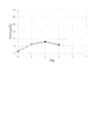
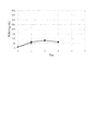
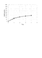
- FIG. 4 is a diagram showing the time course of the creatinine concentration in the kidney in Experiment 1.
- FIG. 5 is a diagram showing the time course of kidney urea nitrogen concentration (BUN) in Experiment 1.
- FIG. 6 is a diagram showing the time course of creatinine concentration in the kidney in Experiment 2.
- FIG. 7 is a diagram showing the time course of kidney urea nitrogen concentration (BUN) in Experiment 2.
- FIG. 8 is a diagram showing the time course of the creatinine concentration in the kidney in Experiment 3.
- FIG. 9 is a diagram showing the time course of kidney urea nitrogen concentration (BUN) in Experiment 3.
- the threshold value of the measurement value of the pressure gauge 45 is preferably 100 mmHg or less.
- the threshold value is preferably smaller than the blood pressure band in a healthy living body of the blood vessel to which the inflow pipe is connected.
- the threshold is preferably equal to or lower than 130 mmHg, which is the lower limit of the normal systolic blood pressure band in the aorta.
- the threshold is set to 100 mmHg or less, which is the lower limit of the systolic blood pressure band of low blood pressure. Note that the threshold is not limited to the organ that has been verified.
- FIG. 10 is a schematic diagram showing the configuration of the perfusion apparatus 1A.
- the perfusion apparatus 1A has two perfusion liquid inflow sections 40.
- Other configurations of the perfusion apparatus 1A are the same as those of the perfusion apparatus 1 according to the first embodiment.
- This perfusion apparatus 1A is used, for example, to perform a perfusion process on the liver 9A.
- two inflow pipes 41 are connected to the portal vein and the hepatic artery of the liver 9A, respectively.
- the discharge pipe 51 is connected to the upper hepatic inferior vena cava (SH-IVC) or the lower hepatic inferior vena cava (IH-IVC) of the liver 9A.
- the hepatic artery is an arterial system, and the pressure of blood in the hepatic artery is large.
- the portal vein is a venous system, and the pressure of blood in the portal vein is much smaller than the pressure in the hepatic artery. For this reason, in this perfusion apparatus 1A, the threshold value of the pressure of the perfusate in the inflow pipe 41 connected to the hepatic artery and the threshold value of the pressure of the perfusate in the inflow pipe 41 connected to the portal vein are individually set. .
- the control unit 60 sets the threshold value of the pressure of the perfusate to 500 mmHg or less for the pump 42 inserted in the inflow pipe 41 connected to the hepatic artery of the liver 9A, Is controlled with the maximum value of 240 to 360 ml / min.
- the control unit 60 sets the threshold value of the pressure of the perfusate to 40 mmHg or less, and sets the maximum value of the amount of perfusate to be sent. Is controlled as 840 to 960 ml / min.
- the threshold of the pressure of the perfusate and the maximum value of the amount of perfusate may be different for each of the inflow pipes 41.
- Some organs to be perfused may have a plurality of inflow blood vessels having different blood pressure values in the living body.
- the threshold value of the pressure of the perfusate or the maximum value of the amount of liquid delivered may be set according to each blood vessel.
- the perfusion apparatus 1 according to the first embodiment has one inflow pipe 41 and one outflow pipe 51. Further, the perfusion apparatus 1A according to the second embodiment has two inflow pipes 41 and one discharge pipe 51. However, the present invention is not limited to this. In the perfusion apparatus of the present invention, the number of the perfusate inflow portion and the number of the perfusion solution discharge portion may be one or more.
- the pipe connected to the reservoir was directly connected to the blood vessel of the organ. That is, the end of the pipe connected to the reservoir served as a cannula.
- a separate member cannula may be connected to the distal ends of the inflow pipe and the discharge pipe, and the cannula may be connected to a blood vessel.
Landscapes
- Engineering & Computer Science (AREA)
- Life Sciences & Earth Sciences (AREA)
- Mechanical Engineering (AREA)
- General Engineering & Computer Science (AREA)
- Health & Medical Sciences (AREA)
- Dentistry (AREA)
- General Health & Medical Sciences (AREA)
- Wood Science & Technology (AREA)
- Zoology (AREA)
- Environmental Sciences (AREA)
- Agricultural Chemicals And Associated Chemicals (AREA)
- Control Of Positive-Displacement Pumps (AREA)
Abstract
La présente invention concerne un dispositif de perfusion (1) qui comprend : un réservoir (30) dans lequel une solution de perfusion est retenue ; un tuyau d'entrée (41) à travers lequel la solution de perfusion peut s'écouler à partir du réservoir (30) dans un organe interne (9) ; un tuyau d'évacuation (51) à travers lequel la solution de perfusion est évacuée à partir de l'organe interne (9) ; une pompe (42) qui administre la solution de perfusion du réservoir (30) à l'organe interne (9) à travers le tuyau d'entrée (41) ; une unité de mesure de pression (45) qui mesure la pression de la solution de perfusion sur le côté le plus en aval à l'intérieur du tuyau d'entrée (41) ; et une unité de commande (60) qui commande la quantité de solution devant être administrée par la pompe (42). L'unité de commande (60) effectue une commande de rétroaction sur la pompe (42) de façon à ne pas amener la valeur de mesure de l'unité de mesure de pression (45) à dépasser un seuil prédéterminé. Grâce à cette configuration, il est possible de réduire au minimum les dommages infligés à un organe interne en raison de l'entrée de solution de perfusion, et de préserver ainsi un organe extrait dans un état davantage préférable.
Applications Claiming Priority (2)
| Application Number | Priority Date | Filing Date | Title |
|---|---|---|---|
| JP2018122914A JP2020002062A (ja) | 2018-06-28 | 2018-06-28 | 灌流装置および灌流方法 |
| JP2018-122914 | 2018-06-28 |
Publications (1)
| Publication Number | Publication Date |
|---|---|
| WO2020004088A1 true WO2020004088A1 (fr) | 2020-01-02 |
Family
ID=68986471
Family Applications (1)
| Application Number | Title | Priority Date | Filing Date |
|---|---|---|---|
| PCT/JP2019/023752 Ceased WO2020004088A1 (fr) | 2018-06-28 | 2019-06-14 | Dispositif de perfusion et procédé de perfusion |
Country Status (2)
| Country | Link |
|---|---|
| JP (1) | JP2020002062A (fr) |
| WO (1) | WO2020004088A1 (fr) |
Cited By (2)
| Publication number | Priority date | Publication date | Assignee | Title |
|---|---|---|---|---|
| CN111849749A (zh) * | 2020-03-31 | 2020-10-30 | 同济大学 | 一种成年小动物心肌细胞高效分离系统 |
| WO2021181985A1 (fr) * | 2020-03-10 | 2021-09-16 | 株式会社Screenホールディングス | Dispositif de perfusion |
Families Citing this family (2)
| Publication number | Priority date | Publication date | Assignee | Title |
|---|---|---|---|---|
| JP7406211B2 (ja) * | 2020-10-14 | 2023-12-27 | 株式会社島津製作所 | 臓器灌流装置および制御方法 |
| EP4635296A1 (fr) | 2022-12-13 | 2025-10-22 | Shimadzu Corporation | Dispositif de perfusion d'organe |
Citations (1)
| Publication number | Priority date | Publication date | Assignee | Title |
|---|---|---|---|---|
| WO2017200089A1 (fr) * | 2016-05-20 | 2017-11-23 | 株式会社Screenホールディングス | Appareil de perfusion pour greffe de foie, et procédé d'isolement de foie et procédé de greffe de foie utilisant ledit appareil |
Family Cites Families (10)
| Publication number | Priority date | Publication date | Assignee | Title |
|---|---|---|---|---|
| US5723282A (en) * | 1991-07-08 | 1998-03-03 | The American National Red Cross | Method of preparing organs for vitrification |
| JPH06305901A (ja) * | 1993-04-26 | 1994-11-01 | Akio Kawamura | 室温下保存用灌流液およびこれを用いた保存方法 |
| US5843024A (en) * | 1996-05-17 | 1998-12-01 | Breonics, Inc. | Solution and process for resuscitation and preparation of ischemically damaged tissue |
| US6100082A (en) * | 1997-09-23 | 2000-08-08 | Hassanein; Waleed H. | Perfusion apparatus and method including chemical compositions for maintaining an organ |
| US7749693B2 (en) * | 1998-09-29 | 2010-07-06 | Lifeline Scientific, Inc. | Method of determining that an organ is not suitable for transplantation and using it for testing substances |
| JP2003206201A (ja) * | 2001-12-28 | 2003-07-22 | Katsutoshi Naruse | 臓器収納装置を含む移植用臓器保存装置および該収納装置を含む人工臓器システム |
| EP1553828A4 (fr) * | 2002-09-18 | 2006-05-17 | Lifeblood Medical Inc | Appareil et procede de conservation et de transport d'organes |
| ES2330404B1 (es) * | 2008-05-19 | 2010-09-22 | Universidad De Barcelona | Solucion acuosa para la preservacion de tejidos y organos. |
| US10575515B2 (en) * | 2010-05-04 | 2020-03-03 | The General Hospital Corporation | Methods and compositions for preserving tissues and organs |
| JP2013075888A (ja) * | 2011-09-15 | 2013-04-25 | Tokyo Metropolitan Univ | 臓器保存装置 |
-
2018
- 2018-06-28 JP JP2018122914A patent/JP2020002062A/ja active Pending
-
2019
- 2019-06-14 WO PCT/JP2019/023752 patent/WO2020004088A1/fr not_active Ceased
Patent Citations (1)
| Publication number | Priority date | Publication date | Assignee | Title |
|---|---|---|---|---|
| WO2017200089A1 (fr) * | 2016-05-20 | 2017-11-23 | 株式会社Screenホールディングス | Appareil de perfusion pour greffe de foie, et procédé d'isolement de foie et procédé de greffe de foie utilisant ledit appareil |
Non-Patent Citations (2)
| Title |
|---|
| HAMEED, AHMER M. ET AL., ANZ J SURG, vol. 88, no. 5, 11 May 2018 (2018-05-11), pages E429 - E434 * |
| MATSUNO, NAOTO ET AL., TRANSPLANTATION NOW, vol. 24, no. 3, 2011, pages 269 - 275 * |
Cited By (6)
| Publication number | Priority date | Publication date | Assignee | Title |
|---|---|---|---|---|
| WO2021181985A1 (fr) * | 2020-03-10 | 2021-09-16 | 株式会社Screenホールディングス | Dispositif de perfusion |
| JP2021143128A (ja) * | 2020-03-10 | 2021-09-24 | 株式会社Screenホールディングス | 灌流装置 |
| US20230129709A1 (en) * | 2020-03-10 | 2023-04-27 | SCREEN Holdings Co., Ltd. | Perfusion apparatus |
| EP4118967A4 (fr) * | 2020-03-10 | 2023-09-13 | SCREEN Holdings Co., Ltd. | Dispositif de perfusion |
| CN111849749A (zh) * | 2020-03-31 | 2020-10-30 | 同济大学 | 一种成年小动物心肌细胞高效分离系统 |
| CN111849749B (zh) * | 2020-03-31 | 2022-02-18 | 同济大学 | 一种成年小动物心肌细胞高效分离系统 |
Also Published As
| Publication number | Publication date |
|---|---|
| JP2020002062A (ja) | 2020-01-09 |
Similar Documents
| Publication | Publication Date | Title |
|---|---|---|
| WO2020004088A1 (fr) | Dispositif de perfusion et procédé de perfusion | |
| US7410474B1 (en) | Methods and means for extracorporeal organ perfusion | |
| US11154051B2 (en) | Apparatus for testing, assessment, and maintenance of harvested hearts for transplanting | |
| US9089126B2 (en) | Methods and apparatus for organ support | |
| US9259521B2 (en) | Method and apparatus for monitoring and optimizing blood circulation generated by a pump | |
| CN106659150B (zh) | 用于维护被收获的待移植心脏的设备 | |
| CN107734967B (zh) | 在获得的可移植的心脏中调节钙离子稳态 | |
| SE0901235A1 (sv) | Förfarande, anordning och vätska för behandling av ett hjärta efter uttagning | |
| Madrahimov et al. | Novel mouse model of cardiopulmonary bypass | |
| EP4005382A1 (fr) | Fluide de perfusion et procédé de perfusion | |
| JP7278898B2 (ja) | 灌流装置 | |
| Kuntz et al. | Effects of conventional ultrafiltration on renal performance during adult cardiopulmonary bypass procedures | |
| WO2020004295A1 (fr) | Dispositif de perfusion et procédé de perfusion | |
| WO2023112555A1 (fr) | Dispositif de conservation d'organe et procédé de conservation d'organe | |
| AU2004201245B2 (en) | Methods and means for extracorporeal organ perfusion | |
| Abendroth | Na-K/2CI transporter inhibition for reduction of postischemic kidney failure tested in autologous reperfusion | |
| HK40062121A (en) | Method and apparatus for reconditioning kidneys | |
| EA045517B1 (ru) | Способ и аппарат для восстановления органов | |
| Gullón Vega | Normothermic perfusion ofan isolated liver: control software implementation | |
| Neyrinck et al. | Donor organ management | |
| JP2020049177A (ja) | 人工肺装置に用いる圧力推定システム | |
| JPWO2019064443A1 (ja) | 臓器保存方法および臓器移植方法 | |
| WO2007106912A2 (fr) | Agonistes du récepteur-alpha activé de la prolifération des peroxysomes pour la conservation d'organe |
Legal Events
| Date | Code | Title | Description |
|---|---|---|---|
| 121 | Ep: the epo has been informed by wipo that ep was designated in this application |
Ref document number: 19825492 Country of ref document: EP Kind code of ref document: A1 |
|
| NENP | Non-entry into the national phase |
Ref country code: DE |
|
| 122 | Ep: pct application non-entry in european phase |
Ref document number: 19825492 Country of ref document: EP Kind code of ref document: A1 |