WO2020004283A1 - Matière imprimée, procédé d'application de brillant et procédé de fabrication de matière imprimée - Google Patents
Matière imprimée, procédé d'application de brillant et procédé de fabrication de matière imprimée Download PDFInfo
- Publication number
- WO2020004283A1 WO2020004283A1 PCT/JP2019/024801 JP2019024801W WO2020004283A1 WO 2020004283 A1 WO2020004283 A1 WO 2020004283A1 JP 2019024801 W JP2019024801 W JP 2019024801W WO 2020004283 A1 WO2020004283 A1 WO 2020004283A1
- Authority
- WO
- WIPO (PCT)
- Prior art keywords
- ridge
- gloss
- printed matter
- base material
- region
- Prior art date
- Legal status (The legal status is an assumption and is not a legal conclusion. Google has not performed a legal analysis and makes no representation as to the accuracy of the status listed.)
- Ceased
Links
Images





Classifications
-
- B—PERFORMING OPERATIONS; TRANSPORTING
- B05—SPRAYING OR ATOMISING IN GENERAL; APPLYING FLUENT MATERIALS TO SURFACES, IN GENERAL
- B05D—PROCESSES FOR APPLYING FLUENT MATERIALS TO SURFACES, IN GENERAL
- B05D5/00—Processes for applying liquids or other fluent materials to surfaces to obtain special surface effects, finishes or structures
- B05D5/06—Processes for applying liquids or other fluent materials to surfaces to obtain special surface effects, finishes or structures to obtain multicolour or other optical effects
- B05D5/061—Special surface effect
-
- B—PERFORMING OPERATIONS; TRANSPORTING
- B05—SPRAYING OR ATOMISING IN GENERAL; APPLYING FLUENT MATERIALS TO SURFACES, IN GENERAL
- B05D—PROCESSES FOR APPLYING FLUENT MATERIALS TO SURFACES, IN GENERAL
- B05D5/00—Processes for applying liquids or other fluent materials to surfaces to obtain special surface effects, finishes or structures
- B05D5/06—Processes for applying liquids or other fluent materials to surfaces to obtain special surface effects, finishes or structures to obtain multicolour or other optical effects
-
- B—PERFORMING OPERATIONS; TRANSPORTING
- B32—LAYERED PRODUCTS
- B32B—LAYERED PRODUCTS, i.e. PRODUCTS BUILT-UP OF STRATA OF FLAT OR NON-FLAT, e.g. CELLULAR OR HONEYCOMB, FORM
- B32B3/00—Layered products comprising a layer with external or internal discontinuities or unevennesses, or a layer of non-planar shape; Layered products comprising a layer having particular features of form
- B32B3/26—Layered products comprising a layer with external or internal discontinuities or unevennesses, or a layer of non-planar shape; Layered products comprising a layer having particular features of form characterised by a particular shape of the outline of the cross-section of a continuous layer; characterised by a layer with cavities or internal voids ; characterised by an apertured layer
- B32B3/30—Layered products comprising a layer with external or internal discontinuities or unevennesses, or a layer of non-planar shape; Layered products comprising a layer having particular features of form characterised by a particular shape of the outline of the cross-section of a continuous layer; characterised by a layer with cavities or internal voids ; characterised by an apertured layer characterised by a layer formed with recesses or projections, e.g. hollows, grooves, protuberances, ribs
-
- B—PERFORMING OPERATIONS; TRANSPORTING
- B32—LAYERED PRODUCTS
- B32B—LAYERED PRODUCTS, i.e. PRODUCTS BUILT-UP OF STRATA OF FLAT OR NON-FLAT, e.g. CELLULAR OR HONEYCOMB, FORM
- B32B7/00—Layered products characterised by the relation between layers; Layered products characterised by the relative orientation of features between layers, or by the relative values of a measurable parameter between layers, i.e. products comprising layers having different physical, chemical or physicochemical properties; Layered products characterised by the interconnection of layers
- B32B7/02—Physical, chemical or physicochemical properties
- B32B7/023—Optical properties
-
- B—PERFORMING OPERATIONS; TRANSPORTING
- B41—PRINTING; LINING MACHINES; TYPEWRITERS; STAMPS
- B41J—TYPEWRITERS; SELECTIVE PRINTING MECHANISMS, i.e. MECHANISMS PRINTING OTHERWISE THAN FROM A FORME; CORRECTION OF TYPOGRAPHICAL ERRORS
- B41J2/00—Typewriters or selective printing mechanisms characterised by the printing or marking process for which they are designed
- B41J2/005—Typewriters or selective printing mechanisms characterised by the printing or marking process for which they are designed characterised by bringing liquid or particles selectively into contact with a printing material
- B41J2/01—Ink jet
-
- B—PERFORMING OPERATIONS; TRANSPORTING
- B41—PRINTING; LINING MACHINES; TYPEWRITERS; STAMPS
- B41M—PRINTING, DUPLICATING, MARKING, OR COPYING PROCESSES; COLOUR PRINTING
- B41M3/00—Printing processes to produce particular kinds of printed work, e.g. patterns
- B41M3/008—Sequential or multiple printing, e.g. on previously printed background; Mirror printing; Recto-verso printing; using a combination of different printing techniques; Printing of patterns visible in reflection and by transparency; by superposing printed artifacts
-
- B—PERFORMING OPERATIONS; TRANSPORTING
- B41—PRINTING; LINING MACHINES; TYPEWRITERS; STAMPS
- B41M—PRINTING, DUPLICATING, MARKING, OR COPYING PROCESSES; COLOUR PRINTING
- B41M3/00—Printing processes to produce particular kinds of printed work, e.g. patterns
- B41M3/06—Veined printings; Fluorescent printings; Stereoscopic images; Imitated patterns, e.g. tissues, textiles
-
- B—PERFORMING OPERATIONS; TRANSPORTING
- B41—PRINTING; LINING MACHINES; TYPEWRITERS; STAMPS
- B41M—PRINTING, DUPLICATING, MARKING, OR COPYING PROCESSES; COLOUR PRINTING
- B41M5/00—Duplicating or marking methods; Sheet materials for use therein
- B41M5/0041—Digital printing on surfaces other than ordinary paper
- B41M5/0047—Digital printing on surfaces other than ordinary paper by ink-jet printing
-
- B—PERFORMING OPERATIONS; TRANSPORTING
- B41—PRINTING; LINING MACHINES; TYPEWRITERS; STAMPS
- B41M—PRINTING, DUPLICATING, MARKING, OR COPYING PROCESSES; COLOUR PRINTING
- B41M5/00—Duplicating or marking methods; Sheet materials for use therein
- B41M5/0041—Digital printing on surfaces other than ordinary paper
- B41M5/0058—Digital printing on surfaces other than ordinary paper on metals and oxidised metal surfaces
-
- B—PERFORMING OPERATIONS; TRANSPORTING
- B41—PRINTING; LINING MACHINES; TYPEWRITERS; STAMPS
- B41M—PRINTING, DUPLICATING, MARKING, OR COPYING PROCESSES; COLOUR PRINTING
- B41M5/00—Duplicating or marking methods; Sheet materials for use therein
- B41M5/0041—Digital printing on surfaces other than ordinary paper
- B41M5/0064—Digital printing on surfaces other than ordinary paper on plastics, horn, rubber, or other organic polymers
-
- B—PERFORMING OPERATIONS; TRANSPORTING
- B41—PRINTING; LINING MACHINES; TYPEWRITERS; STAMPS
- B41M—PRINTING, DUPLICATING, MARKING, OR COPYING PROCESSES; COLOUR PRINTING
- B41M5/00—Duplicating or marking methods; Sheet materials for use therein
- B41M5/0041—Digital printing on surfaces other than ordinary paper
- B41M5/007—Digital printing on surfaces other than ordinary paper on glass, ceramic, tiles, concrete, stones, etc.
-
- B—PERFORMING OPERATIONS; TRANSPORTING
- B41—PRINTING; LINING MACHINES; TYPEWRITERS; STAMPS
- B41M—PRINTING, DUPLICATING, MARKING, OR COPYING PROCESSES; COLOUR PRINTING
- B41M5/00—Duplicating or marking methods; Sheet materials for use therein
- B41M5/0041—Digital printing on surfaces other than ordinary paper
- B41M5/0076—Digital printing on surfaces other than ordinary paper on wooden surfaces, leather, linoleum, skin, or flowers
-
- B—PERFORMING OPERATIONS; TRANSPORTING
- B05—SPRAYING OR ATOMISING IN GENERAL; APPLYING FLUENT MATERIALS TO SURFACES, IN GENERAL
- B05D—PROCESSES FOR APPLYING FLUENT MATERIALS TO SURFACES, IN GENERAL
- B05D1/00—Processes for applying liquids or other fluent materials
- B05D1/26—Processes for applying liquids or other fluent materials performed by applying the liquid or other fluent material from an outlet device in contact with, or almost in contact with, the surface
-
- B—PERFORMING OPERATIONS; TRANSPORTING
- B05—SPRAYING OR ATOMISING IN GENERAL; APPLYING FLUENT MATERIALS TO SURFACES, IN GENERAL
- B05D—PROCESSES FOR APPLYING FLUENT MATERIALS TO SURFACES, IN GENERAL
- B05D5/00—Processes for applying liquids or other fluent materials to surfaces to obtain special surface effects, finishes or structures
- B05D5/06—Processes for applying liquids or other fluent materials to surfaces to obtain special surface effects, finishes or structures to obtain multicolour or other optical effects
- B05D5/061—Special surface effect
- B05D5/063—Reflective effect
-
- B—PERFORMING OPERATIONS; TRANSPORTING
- B05—SPRAYING OR ATOMISING IN GENERAL; APPLYING FLUENT MATERIALS TO SURFACES, IN GENERAL
- B05D—PROCESSES FOR APPLYING FLUENT MATERIALS TO SURFACES, IN GENERAL
- B05D7/00—Processes, other than flocking, specially adapted for applying liquids or other fluent materials to particular surfaces or for applying particular liquids or other fluent materials
- B05D7/50—Multilayers
- B05D7/52—Two layers
- B05D7/53—Base coat plus clear coat type
Definitions
- the present invention relates to a printed matter, a gloss imparting method, and a printed matter manufacturing method. More specifically, the present invention provides a printed material in which a special surface gloss (shine) is provided on a substrate having various patterns by providing a plurality of regions having different glosses on the surface of the substrate. The present invention relates to a method and a method for producing printed matter.
- Patent Literature 1 discloses a decorative sheet having a woodgrain provided on the surface of a base material.
- the wood skin of specific wood such as hard maple and mahogany shows a special surface gloss (shine) called a heather (quilt heather).
- surface gloss is caused by light reflection and scattering from the interior of the cells of the wood that received the light, and the pattern shines so that the pattern fluctuates three-dimensionally depending on the viewing angle, showing excellent design and luxury.
- Due to the limited types of wood showing such quilt heathers and various strengths among quilt heathers woods showing strong quilt heathers are often traded at high prices.
- the woodgrain formed by the invention described in Patent Document 1 cannot provide a special surface gloss (shine) having a three-dimensional effect like a quilt heather.
- various patterns having such special surface gloss for example, a metal-like pattern is given a special surface gloss (shine) having a three-dimensional effect, such as the above-mentioned quilt heather, which cannot be originally generated with metal.
- the printed matter with the (painted pattern) is not known.
- the present invention has been made in view of such a conventional problem, and provides a printed material in which a special surface gloss (shine) is expressed on various patterns, a gloss applying method, and a printed material manufacturing method.
- the purpose is to:
- the present inventor forms a plurality of regions each including a plurality of ridges extending along different directions on the surface of the base material with a light-transmitting ink, and uses a difference in gloss indicated by each region as a visual effect. It has been found that the above problem can be suitably solved by utilizing the present invention, and the present invention has been completed.
- the printed matter of the present invention that solves the above problems includes a base material, and a gloss layer provided on the base material, wherein the gloss layer is made of a translucent ink, and has a surface on the base material.
- the gloss imparting method of the present invention for solving the above-mentioned problem is a gloss imparting method of imparting a surface gloss by providing a translucent ink on a base material to provide a gloss layer, and on the surface of the gloss layer, A second region including a first ridge along a first direction in the plane and including a second ridge along a second direction different from the first direction Is a gloss imparting method including a step of applying the translucent ink so as to form.
- a method for producing a printed matter of the present invention which solves the above-mentioned problem is a method for producing a printed matter having a surface gloss, and an ink for forming a glossy layer by applying a translucent ink to a base material by an inkjet method.
- An ink applying step wherein the ink applying step forms a first region including a first ridge along a first in-plane direction on a surface of the base material, and the first direction includes:
- a printed matter manufacturing method which is a step of applying the translucent ink so as to form a second region including a second ridge along a different second direction.
- the printed matter of the present invention that more suitably solves the above-mentioned problems includes a base material, and a gloss layer provided on the base material, wherein the base material is a steel plate, a metal plate, a plastic plate, a film, At least one selected from the group consisting of ceramic boards, concrete, wood, glass, and fabric (except when the base material is a transparent member), and the glossy layer is made of a translucent ink; On the surface of the base material, a first region including a first ridge formed along a first direction in the plane, and a second region formed along a second direction different from the first direction. And a second region including two ridges, wherein the first ridge is curved from the first direction to the second direction, and is connected to the second ridge. It is a printed matter including a part.
- a gloss imparting method of the present invention that more suitably solves the above problem is a gloss imparting method of imparting a surface gloss by applying a translucent ink to a substrate and providing a gloss layer, wherein the substrate is And at least one selected from the group consisting of a steel plate, a metal plate, a plastic plate, a film, a ceramic plate, concrete, wood, glass and a fabric (except when the base material is a transparent member), and the gloss A first area including a first ridge is formed on a surface of the layer along a first direction in the plane, and a second ridge is formed along a second direction different from the first direction.
- a method for producing a printed matter of the present invention that more suitably solves the above-mentioned problem is a method for producing a printed matter having a surface gloss, and a light-transmitting ink is applied to a base material by an inkjet method to form a glossy layer.
- the ink applying step forms a first region including a first ridge on a surface of the base material along a first direction in the plane, and the first area includes a first ridge.
- a step of applying the translucent ink so as to form a second region including a second ridge along a second direction different from the direction, wherein the first ridge includes the first ridge.
- Kutomo is one (unless the substrate is a transparent member), a method for producing a printed product.
- the printed matter of the present invention that more suitably solves the above-mentioned problem includes a base material, and a gloss layer provided on the base material, wherein the gloss layer is made of a translucent ink, A first region including a first ridge formed along a first direction in the plane, and a second region formed along a second direction different from the first direction. A second region including a ridge is formed, and the base material is a light-transmitting base material, and further includes a design layer, and the base material, the gloss layer, and the design layer are arranged in this order.
- the first ridge is a printed matter that is curved from the first direction to the second direction and includes a curved portion connected to the second ridge.
- FIG. 1 is a schematic plan view of a printed matter according to one embodiment of the present invention.
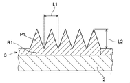
- FIG. 2 is a schematic cross-sectional view of the first ridge.
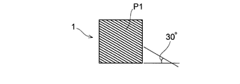
- FIG. 3 is a schematic plan view showing the angle at which the first ridge extends.
- FIG. 4 is a schematic plan view showing the angle at which the first ridge extends.
- FIG. 5 is a schematic plan view showing the angle at which the first ridge extends.
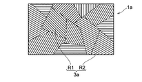
- FIG. 6 is a schematic plan view related to a modification of the printed matter according to the embodiment of the present invention.
- FIG. 7 is a schematic diagram for explaining a layer structure of a printed matter in which a design layer is provided between a base material and a gloss layer.
- FIG. 8 is a schematic diagram for explaining a layer configuration of a printed matter in which a design layer is provided on a gloss layer.
- a printed material according to one embodiment of the present invention includes a base material and a gloss layer provided on the base material.
- FIG. 1 is a schematic plan view of a printed matter 1 of the present embodiment.
- the glossy layer 3 is made of a translucent ink, and includes a first region R1 including a first ridge P1 formed on the surface of the base material 2 along a first direction in the plane, and a first direction R1. And a second region R2 including a second ridge P2 formed along a second direction different from the second direction.
- the substrate 2 is not particularly limited.
- the substrate 2 may be a transparent substrate showing translucency or an opaque substrate other than the transparent substrate.
- the substrate 2 is a metal plate such as a steel plate, aluminum, stainless steel, etc., a plastic plate or film such as acrylic, polycarbonate, ABS, polypropylene, polyester, vinyl chloride, etc., a ceramic plate, concrete, wood, glass, etc. .
- the base material 2 is made of cationic dyeable polyester (CDP) fiber, polyethylene terephthalate (PET) fiber, polybutylene terephthalate (PBT) fiber, polytrimethylene terephthalate (PTT) fiber, wholly aromatic polyester fiber, polylactic acid fiber, etc.
- CDP cationic dyeable polyester
- PET polyethylene terephthalate
- PBT polybutylene terephthalate
- PTT polytrimethylene terephthalate
- Polyester fiber acetate fiber, triacetate fiber, polyurethane fiber, nylon fiber, or the like, or a fabric made of a composite fiber thereof. These can be appropriately selected depending on the application.
- the cloth is preferably treated with a pretreatment agent before printing.
- Pretreatment agents include water-soluble polymers, water-insoluble inactive organic compounds, flame retardants, ultraviolet absorbers, reduction inhibitors, antioxidants, pH adjusters, hydrotropic agents, defoamers, penetrants, microporous A forming agent and the like are exemplified.
- the transparent substrate refers to a substrate having a degree of transparency such that, for example, when a design or the like is arranged on the back surface side of the substrate, the arranged design can be viewed from the front surface side.
- the base material of the present embodiment may be subjected to painting, pretreatment, or the like on at least one of the front surface and the back surface. In this case, a substrate having lost transparency due to painting or pretreatment is included in an opaque substrate that is not a transparent substrate.
- the printed matter 1 of the present embodiment can be given a special surface gloss (shine) as shown by a specific wood. Therefore, for example, when the base material 2 is a wood raw material, the printed matter 1 is made of such a material even if a wood raw material that does not exhibit a special surface gloss (shine) is used as the base material 2.
- the special substrate 2 can be given a special surface gloss (shine) as shown by specific wood. For this reason, the printed matter 1 has a wider range of choices for the material of the base material 2 and can provide various added values such as cost reduction and mass production.
- the base material 2 is a raw material other than wood (for example, a plastic plate such as the above-mentioned polycarbonate plate)
- the printed matter 1 is made of a raw material that does not originally exhibit a special surface gloss (shine).
- a special surface gloss (shine) as shown by a specific wood can also be given to 2.
- the print 1 has a wider range of choices for the material of the base material 2 and can provide various added values such as weight reduction, cost reduction, and mass production.
- the obtained printed matter 1 can be a printed matter made of plastic, cloth, or the like to which a special surface gloss (shine) is imparted, such as that indicated by specific wood, which could not be present in the related art. Since such a printed matter 1 exhibits a special surface gloss, it can exhibit an unprecedented design property.
- the gloss layer 3 is a layer provided on the base material 2 and is formed by applying a translucent ink by an inkjet method.
- the translucent ink is not particularly limited.
- the translucent ink is a water-based ink, a solvent-based ink, a non-solvent-based (monomer dilution) ink, or the like.
- the resin added to the translucent ink is not particularly limited.
- the resin is an ultraviolet curable resin, a thermoplastic resin, a thermosetting resin, or the like.
- the glossy layer 3 includes a first region R1 including a first ridge P1 formed along an in-plane first direction on the surface of the substrate 2 and a second direction different from the first direction.
- a second region R2 including a second ridge P2 formed along is formed. Note that the number of regions provided in the gloss layer 3 of the present embodiment may be two or more.
- FIG. 1 illustrates a case where a surface layer including three regions is provided. The first region R1 and the second region R2 are arbitrary regions selected from these three regions.
- the first region R1 is a region where a first ridge P1 extending along a predetermined direction (first direction) is formed.
- the first ridge P1 is a protrusion extending in the first direction on the surface of the gloss layer 3.
- the first region R1 reflects light and exhibits desired gloss due to the formation of the first ridge P1.
- FIG. 2 is a schematic cross-sectional view of the first ridge P1.
- the first ridge P ⁇ b> 1 of the present embodiment has a sawtooth shape having a vertical cross-sectional shape from the base end to the tip, and the plurality of first ridges P ⁇ b> 1 Are formed adjacent to each other.
- the cross-sectional shape of the first ridge P1 may be another shape (for example, an elliptical shape, a rectangular shape, or the like) in addition to the sawtooth shape. Further, the cross-sectional shape of each first ridge P1 may be different.
- the width (L1) of each first ridge P1 is not particularly limited.
- the width (L1) of the first ridge P1 is appropriately set so as to produce a desired luster.
- the width (L1) of the first ridge P1 is preferably 10 ⁇ m or more, and more preferably 30 ⁇ m or more.
- the width (L1) of the first ridge P1 is preferably 1000 ⁇ m or less, and more preferably 500 ⁇ m or less.
- the width (L1) of each first ridge P1 may be different.
- the height (L2) of each first ridge P1 is not particularly limited.
- the height (L2) of the first ridge P1 is appropriately set so as to produce a desired luster.
- the height (L2) of the first ridge P1 is preferably 30 ⁇ m or more, and more preferably 50 ⁇ m or more.
- the height (L2) of the first ridge P1 is preferably 1000 ⁇ m or less, and more preferably 200 ⁇ m or less.
- the height (L2) of each first ridge P1 may be different.
- each first ridge P1 with respect to the base material 2 is not particularly limited.
- the angle with respect to the substrate 2 can be appropriately adjusted by the width (L1) and the height (L2) of the first ridge P1.
- the angle with respect to the substrate 2 is more than 0 ° and less than 180 °, preferably 10 ° or more and 170 ° or less.
- the direction in which the first ridge P1 extends may be different from the direction in which the second ridge P2 in the second region R2 described later extends. That is, the direction in which the first ridge P1 extends may be a direction at an arbitrary angle of 0 to 180 ° with respect to one side in the horizontal direction of the printed matter 1 in a top view (however, the second ridge P1 may be the second direction) This is different from the direction in which the ridge P2 extends).
- 3 to 5 are schematic plan views showing the angle at which the first ridge P1 extends.
- the direction in which the first ridge P1 extends may be 30 ° (see FIG. 3) or 45 ° with respect to one lateral side of the printed matter 1 in a top view (see FIG. 4). ) Or 60 ° (see FIG. 5).
- the second region R2 is a region where a second ridge P2 extending along a predetermined direction (second direction) different from the first direction is formed.
- the second ridge P2 is a protrusion extending on the surface of the gloss layer 3 in the second direction.
- the second region R2 reflects light due to the formation of the second ridge P2, and exhibits a desired gloss different from the gloss generated by the first region R1. Thereby, the observer who observes the printed matter 1 can obtain a visual effect based on the gloss difference by simultaneously observing a plurality of regions (first region R1 and second region R2) having different gloss.
- the second direction may be different from the first direction. That is, the angle of the second direction with respect to the first direction is not particularly limited.
- the second direction is preferably tilted by 10 ° or more with respect to the first direction in the in-plane direction of the base material 2 (that is, the top view shown in FIG. 1), and more preferably by 20 ° or more. Preferably, it is inclined. Further, the second direction is preferably inclined at an angle of 80 ° or less with respect to the first direction, and is preferably inclined at an angle of 70 ° or less with respect to the in-plane direction of the substrate 2.
- the gloss generated by the second region R2 is easily different from the gloss generated by the first region R1. Thereby, the observer who observes the printed matter 1 can obtain a visual effect based on a larger gloss difference.
- the angle of the second direction with respect to the first direction changes appropriately. It is preferable that the angle be changed within the range of 10 to 80 °.
- the first ridge P1 and the second ridge P2 are not linear, the first ridge P1 and the second ridge P2 partially overlap the first and second directions. May be the same angle.
- the shape, width, and height of the second ridge P2 are the same as those described above in relation to the first ridge P1, and are not particularly limited.
- the shape of the first ridge P1 and the second ridge P2 is not limited to a straight line. That is, the first ridge P1 only needs to include a portion formed along a different direction from the second ridge P2. Therefore, the first ridge P1 and the second ridge P2 may each include a curved portion.
- the first ridge P1 may be curved at an end close to the second ridge P2 so as to be connected to the second ridge P2.
- the printed matter 1 can gradually change its gloss from the gloss derived from the first region R1 to the gloss derived from the second region R2, and has a more natural and three-dimensional special surface gloss (shine). ) Can be expressed.
- the first region R1 and the second region R2 described above may be formed on the entire surface of the base material 2 or may be partially formed.
- the remaining region may be a region in which the gloss layer 3 is formed flat.
- the third region R3 including the third ridge P3 formed along a direction different from the first ridge P1 and the second ridge P2 may be an unexposed surface of the substrate 2. There may be.
- the third ridge P3 is similar to the first ridge P1 or the second ridge P2 described above.
- the printed matter 1 shown in FIG. 1 is formed such that the first region R1 and the second region R2 are adjacent to each other.
- the printed matter 1 has a third region R3 including a third ridge P3 in addition to the first region R1 and the second region R2.
- a region including a predetermined ridge is formed on the entire surface of the gloss layer 3.
- the printed matter 1 becomes more three-dimensional due to the influence of the gloss based on the first region R1 to the third region R3 and the gloss difference based on the gloss.
- a special surface gloss (shine) with a feeling can be exhibited.
- FIG. 6 is a schematic plan view related to a modified example of the printed matter (printed matter 1a) of the present embodiment. As shown in FIG. 6, a first region R1 and a second region R2 formed at a position separated from the first region R1 are formed on the gloss layer 3a of the printed matter 1a. Thereby, the printed matter 1a can show different surface gloss (shine) as compared with the case where the first region R1 and the second region R2 are formed adjacent to each other (see FIG. 1).
- the areas of the first area P1 and the second area P2 are each 1 mm in order to satisfactorily express a special surface gloss (shine) as indicated by specific wood. It preferred to be formed so as to be 2 or more, and more preferably formed so as to be 5 mm 2 or more. When the area of the region is in the above range, the printed matter 1 can easily make the observer recognize the gloss and the gloss difference derived from each region, and easily exert a special visual effect of surface gloss.
- FIG. 7 is a schematic diagram for explaining a layer configuration of a printed matter (printed matter 1b) in which the design layer 4 is provided between the base material 2b and the gloss layer 3b. Note that, in FIG. 7, an arrow A indicates a direction in which light is incident.
- the design layer 4 is not particularly limited.
- the design layer 4 is a layer on which various patterns and patterns are formed, and has various woodgrain, metal, carbon, synthetic leather, natural leather, stone, and various geometric patterns. , A photograph and the like are formed.
- the gloss layer 3b made of the above-described light-transmitting ink is formed on the design layer 4. Therefore, the printed matter 1b is a product that reflects light on the surface, and a special surface gloss (shine) as indicated by specific wood is given to the design layer 4 on which various designs and patterns are formed. ing.
- the design layer 4 is a layer on which the woodgrain is printed.
- the printed matter 1b has a woodgrain provided with a special surface gloss (shine) as shown by a specific wood, even when a substrate 2b other than wood is used. Tones can be formed. Therefore, the printed matter 1b has a wider range of choices for the material of the base material 2b, and is given various added values such as weight reduction and cost reduction.
- FIG. 8 is a schematic diagram for explaining a layer configuration of a printed matter 1c in which the design layer 4 is provided on the gloss layer 3c. Note that, in FIG. 8, an arrow A indicates a direction in which light is incident.
- a printed matter 1c is a product that reflects light on the back surface because the base material 2c shows translucency, and a specific wood shows a design layer 4 on which various designs and patterns are formed.
- Such special surface gloss (shine) is given.
- the translucent material forming the substrate 2c is not particularly limited.
- the light-transmitting material may be an inorganic material such as glass, water glass, low-melting glass, silicon resin, or alkoxysilane, acrylic resin, acrylic-styrene resin, acrylic silicon resin, cellulose acetobutyrate resin, Organic materials such as cellulose propionate resin, polymethylpentene resin, polycarbonate resin, polystyrene resin, polyester resin, epoxy resin and urethane resin.
- the light-transmitting material forming the base material 2c and the resin material forming the glossy layer 3c be different types. That is, when the light-transmitting material forming the base material 2c and the resin material forming the gloss layer 3c show the same or similar light-transmitting properties, if the gloss layer 3c is provided on the base material 2c, This is because it is difficult to determine a gloss difference between the gloss generated by the first region R1 and the gloss generated by the second region R2. Since the translucent material constituting the base material 2c is of a different type from the resin material constituting the gloss layer 3c, the printed matter 1c has a gloss produced by the first region R1 and a gloss produced by the second region R2. Is difficult to reduce, and it is easy to show a special surface gloss (shine) as shown by specific wood.
- the first region including the first ridge formed on the surface of the base material along the first direction in the plane is different from the first direction.
- a second region including a second ridge formed along the second direction is formed. Therefore, the observer who observes the printed matter sees the gloss caused by the reflection of the light by the first ridge in the first area and the gloss caused by the reflection of the light by the second ridge in the second area at the same time.
- a visual effect based on the gloss difference of each gloss is obtained.
- Such a visual effect is similar to a special surface gloss (shine) having a three-dimensional effect, such as a quilt heather.
- the printed matter can exhibit a special surface gloss (shine) as shown by specific wood.
- the printed matter of the present embodiment can impart the above-mentioned special surface gloss (shine) to various substrates.
- the printed matter is used as various products and parts such as furniture, home electric appliances, interior parts of automobiles, building materials, and the like, and can give a sense of quality and the like in these uses.
- the type of the printed material is not particularly limited. Therefore, for example, by printing a woodgrain pattern on the base material, the printed matter can impart a special surface gloss to the wood grain that does not originally exhibit the special surface gloss.
- the printed matter can impart the special surface gloss to a base material having a pattern other than wood grain (for example, metal tone, synthetic leather tone, various geometric patterns, etc.). Therefore, the obtained printed matter can express various designs which have not existed conventionally.
- Each of the first ridge and the second ridge of the present embodiment has a sharp sawtooth shape from the base end to the tip, and stands upright from the surface of the gloss layer (or the base material).
- the shape of the first ridge and the second ridge of the present embodiment is not limited to such an upright shape. That is, the first ridge and the second ridge may be formed by forming a plurality of grooves parallel to the surface of the gloss layer after the gloss layer having a predetermined thickness is formed.
- the method for producing a printed matter according to one embodiment of the present invention includes an ink applying step of applying a translucent ink to a base material by an inkjet method to form a gloss layer.
- a first region including a first ridge is formed on the surface of the substrate along a first direction in the plane, and along a second direction different from the first direction.
- This is a step of applying a translucent ink so as to form a second region including a second ridge.
- the method for producing a printed matter according to the present embodiment is characterized by an ink application step. Therefore, the other steps than the ink applying step are the same as the steps employed in the conventional printed matter manufacturing method. Therefore, steps other than the ink applying step described below are only examples, and the design can be changed as appropriate.
- the ink application step is a step of providing a glossy layer by applying a light-transmissive ink on a base material by an inkjet method.
- the ink applying step includes forming a first region including a first ridge on the surface of the base material along a first direction in the surface, and a second direction different from the first direction.
- the translucent ink is applied so as to form a second region including a second ridge along.
- the ink jet system is not particularly limited.
- the ink jet method is a charge modulation method, a micro dot method, a charge jet control method, a continuous method such as an ink mist method, a piezo method, a pulse jet method, a bubble jet (registered trademark) method, an electrostatic suction method, and the like.
- On-demand system Further, the ink jet system may be adopted as either a line type of fixing a recording head and ejecting the recording medium onto a recording medium, or a serial type of moving a recording head relative to the recording medium.
- the amount of ink applied is not particularly limited.
- the application amount of the ink can be appropriately adjusted according to the thickness of the gloss layer, the dimension of the ridge, and the like necessary to exhibit a desired gloss difference.
- the substrate to which the ink has been applied may be subjected to a curing treatment or a drying treatment as appropriate.
- the obtained printed matter has a gloss due to light being reflected by the first ridge in the first region and a second ridge in the second region. This imparts gloss due to light reflection.
- These different glosses enter the field of view at the same time as the observer views the print, giving a visual effect based on the gloss difference between the respective glosses.
- Such a visual effect is similar to a special surface gloss (shine) having a three-dimensional effect, such as a quilt heather.
- the printed matter manufacturing method can impart a special surface gloss (shine) as indicated by specific wood to various substrates.
- the method for manufacturing a printed matter of the present embodiment may employ a design layer forming step of forming a design layer on a substrate before the above-described ink applying step.
- the design layer can be formed on the substrate by a known inkjet method.
- the base material on which the design layer is formed is provided with a gloss layer in the ink applying step.
- the obtained printed matter is a product that reflects light on the surface, and a special surface gloss (shine) as given by specific wood is given to the design layer on which various designs and patterns are formed. .
- the gloss imparting method is a gloss imparting method in which a translucent ink is applied on a base material to form a gloss layer and impart surface gloss.
- a first region including a first ridge is formed on a surface of the gloss layer along a first direction in the plane, and along a second direction different from the first direction.
- the substrate, gloss layer, and translucent ink used in the present embodiment are all the same as those described above in the embodiment of the printed matter and the method of manufacturing the printed matter. Further, a specific method of providing a translucent ink on a base material to provide a gloss layer is as described above in relation to the embodiment of the method for manufacturing a printed matter.
- the obtained printed matter is glossy due to light being reflected by the first ridge in the first area, and light is reflected by the second ridge in the second area. And the resulting gloss.
- These different glosses enter the field of view at the same time as the observer views the print, giving a visual effect based on the gloss difference between the respective glosses.
- Such a visual effect is similar to a special surface gloss (shine) having a three-dimensional effect, such as a quilt heather.
- the gloss imparting method can impart a special surface gloss (shine) as indicated by specific wood to various substrates.
- a special surface gloss (shine) as indicated by a specific wood can be applied to a substrate other than the specific wood.
- the gloss imparting method can impart a sophisticated design which could not be achieved conventionally to various substrates, and can produce a printed matter having excellent design properties.
- the embodiment of the present invention has been described above.
- the present invention is not particularly limited to the above embodiment.
- the above embodiment mainly describes the invention having the following configuration.
- a substrate comprising a gloss layer provided on the substrate, wherein the gloss layer is made of a translucent ink, and is provided on the surface of the substrate along a first in-plane direction.
- a first region including the formed first ridge and a second region including a second ridge formed along a second direction different from the first direction are formed.
- the printed matter is different from the first direction including the first ridge formed on the surface of the base material along the first direction in the plane, and the first direction.
- a second region including a second ridge formed along the second direction is formed. Therefore, the observer who observes the printed matter sees the gloss caused by the reflection of the light by the first ridge in the first area and the gloss caused by the reflection of the light by the second ridge in the second area at the same time.
- a visual effect based on the gloss difference of each gloss is obtained.
- Such a visual effect is similar to a special surface gloss (shine) having a three-dimensional effect, such as a quilt heather.
- the printed matter can exhibit a special surface gloss (shine).
- the type of the printed material is not particularly limited. Therefore, for example, by printing a woodgrain pattern on the base material, the printed matter can impart a special surface gloss to the wood grain that does not originally exhibit the special surface gloss. In addition, the printed matter can impart the special surface gloss to a base material having a pattern other than wood grain (for example, metal tone, synthetic leather tone, various geometric patterns, etc.). Therefore, the obtained printed matter can express various designs which have not existed conventionally.
- the printed matter can show a special surface gloss (shine) more strongly.
- the printed matter exhibits a special surface gloss (shine) and can change the intensity of the surface gloss.
- the printed matter exhibits a special surface gloss (shine) and can change the intensity of the surface gloss.
- the printed matter in the printed matter, the first region and the second region are connected by the curved portion. Therefore, the printed matter can express a more natural and three-dimensional special surface gloss (shine).
- the printed matter can impart a special surface gloss (shine) to the design layer on which various designs and patterns are formed.
- the printed matter can be a product that reflects light on the surface.
- the base material is a light-transmitting base material, and further includes a design layer, wherein the base material, the gloss layer, and the design layer are sequentially formed, (1) to (5). ).
- the printed matter can impart a special surface gloss (shine) to the design layer on which various designs and patterns are formed. Further, the printed matter can be a product that reflects light on the back surface because the base material transmits light.
- the printed matter can form a woodgrain having a special surface gloss (shine) even when a substrate other than wood is used. For this reason, the printed matter has a wider range of choices for the material of the base material, and can provide various added values such as weight reduction and cost reduction.
- the printed matter can be given a special surface gloss (shine) even when a wood raw material that does not exhibit a special surface gloss (shine) is used as a base material. For this reason, the printed matter has a wider range of choices for the material of the base material, and can provide various added values such as cost reduction.
- a gloss imparting method for imparting a surface gloss by providing a glossy layer by applying a translucent ink on a base material, wherein a first surface is provided on the surface of the gloss layer along a first direction in a plane. Forming the first region including the ridge, and applying the translucent ink so as to form the second region including the second ridge along a second direction different from the first direction.
- a glossing method comprising the step of:
- the resulting printed matter has a gloss due to light being reflected by the first ridge in the first area and a gloss due to light being reflected by the second ridge in the second area.
- These different glosses enter the field of view at the same time as the observer views the print, giving a visual effect based on the gloss difference between the respective glosses.
- Such a visual effect is similar to a special surface gloss (shine) having a three-dimensional effect, such as a quilt heather.
- the gloss imparting method can impart a special surface gloss (shine) to various substrates.
- a method for producing a printed material having a surface gloss comprising an ink applying step of applying a translucent ink to a base material by an ink jet method to form a glossy layer, wherein the ink applying step includes: A first region including a first ridge is formed along a first direction in the plane, and a second ridge is formed along a second direction different from the first direction.
- a method for producing a printed matter which is a step of applying the translucent ink so as to form a second region including the ink.
- the resulting printed matter has a gloss due to light being reflected by the first ridge in the first area and a gloss due to light being reflected by the second ridge in the second area.
- These different glosses enter the field of view at the same time as the observer views the print, giving a visual effect based on the gloss difference between the respective glosses.
- Such a visual effect is similar to a special surface gloss (shine) having a three-dimensional effect, such as a quilt heather.
- the printed matter manufacturing method can impart special surface gloss (shine) to various substrates.
- the present invention preferably has the following configuration.
- A a base material, and a gloss layer provided on the base material, wherein the base material is selected from the group consisting of a steel plate, a metal plate, a plastic plate, a film, a ceramic plate, concrete, wood, glass, and fabric. At least one type selected (except when the substrate is a transparent member), and the glossy layer is made of a translucent ink, and is formed on the surface of the substrate in a first direction in a plane. A first region including a first protrusion formed along the first region, and a second region including a second protrusion formed along a second direction different from the first direction.
- the printed matter, wherein the first ridge is curved from the first direction to the second direction and includes a curved portion connected to the second ridge.
- a gloss imparting method for imparting a surface gloss by providing a glossy layer by applying a translucent ink on a substrate wherein the substrate is a steel plate, a metal plate, a plastic plate, a film, a ceramic plate, concrete , At least one selected from the group consisting of wood, glass and cloth (except when the base material is a transparent member), on the surface of the gloss layer along a first direction in the plane.
- (I) a method for producing a printed matter having a surface gloss comprising an ink applying step of applying a translucent ink to a substrate by an ink jet method to form a gloss layer, wherein the ink applying step includes A first region including a first ridge is formed along a first direction in the plane, and a second ridge is formed along a second direction different from the first direction. A step of applying the translucent ink so as to form a second region including the second ridge, wherein the first ridge is curved from the first direction to the second direction, and the second ridge is curved.
- the substrate is at least one selected from the group consisting of steel plate, metal plate, plastic plate, film, ceramic plate, concrete, wood, glass and fabric ( However, unless the base material is a transparent member) Method of manufacturing the printed matter.
- a base material comprising a glossy layer provided on the base material, wherein the glossy layer is made of a translucent ink, and is provided on the surface of the base material along a first direction in a plane.
- the base material is a light-transmitting base material, further comprising a design layer, the base material, the gloss layer, and the design layer are formed in order, the first ridge, A printed matter that includes a curved portion that curves from a first direction in the second direction and is connected to the second ridge.
Landscapes
- Engineering & Computer Science (AREA)
- Health & Medical Sciences (AREA)
- General Health & Medical Sciences (AREA)
- Textile Engineering (AREA)
- Vascular Medicine (AREA)
- Ceramic Engineering (AREA)
- Life Sciences & Earth Sciences (AREA)
- Wood Science & Technology (AREA)
- Printing Methods (AREA)
- Laminated Bodies (AREA)
- Ink Jet (AREA)
- Application Of Or Painting With Fluid Materials (AREA)
Abstract
La présente invention concerne une matière imprimée pourvue : d'un matériau de base ; et d'une couche brillante qui est disposée sur le matériau de base, le matériau de base étant au moins un élément choisi dans le groupe constitué par une tôle d'acier, une feuille métallique, une feuille de plastique, un film, une feuille céramique, du béton, du bois, du verre et du tissu (sauf lorsque le matériau de base est un élément transparent). La couche brillante est constituée d'une encre translucide. Une première zone comprenant une première saillie formée le long d'une première direction à l'intérieur d'une surface et une seconde zone comprenant une seconde saillie formée le long d'une seconde direction différente de la première direction sont formées sur la surface du matériau de base. La première saillie comprend une partie courbée pliée de la première direction à la seconde direction et raccordée à la seconde saillie.
Priority Applications (2)
| Application Number | Priority Date | Filing Date | Title |
|---|---|---|---|
| CN201980035488.2A CN112203859B (zh) | 2018-06-29 | 2019-06-21 | 打印物、光泽赋予方法以及打印物的制造方法 |
| US17/252,656 US12011737B2 (en) | 2018-06-29 | 2019-06-21 | Printed matter, gloss imparting method, and method for manufacturing printed matter |
Applications Claiming Priority (2)
| Application Number | Priority Date | Filing Date | Title |
|---|---|---|---|
| JP2018124937A JP6531204B1 (ja) | 2018-06-29 | 2018-06-29 | プリント物、光沢付与方法およびプリント物の製造方法 |
| JP2018-124937 | 2018-06-29 |
Publications (1)
| Publication Number | Publication Date |
|---|---|
| WO2020004283A1 true WO2020004283A1 (fr) | 2020-01-02 |
Family
ID=66821734
Family Applications (1)
| Application Number | Title | Priority Date | Filing Date |
|---|---|---|---|
| PCT/JP2019/024801 Ceased WO2020004283A1 (fr) | 2018-06-29 | 2019-06-21 | Matière imprimée, procédé d'application de brillant et procédé de fabrication de matière imprimée |
Country Status (4)
| Country | Link |
|---|---|
| US (1) | US12011737B2 (fr) |
| JP (1) | JP6531204B1 (fr) |
| CN (1) | CN112203859B (fr) |
| WO (1) | WO2020004283A1 (fr) |
Families Citing this family (1)
| Publication number | Priority date | Publication date | Assignee | Title |
|---|---|---|---|---|
| CN117202548B (zh) * | 2022-05-31 | 2025-06-13 | 比亚迪股份有限公司 | 一种工件和电子设备 |
Citations (9)
| Publication number | Priority date | Publication date | Assignee | Title |
|---|---|---|---|---|
| JP2007260501A (ja) * | 2006-03-27 | 2007-10-11 | Kubota Matsushitadenko Exterior Works Ltd | 建築板の塗装方法及び塗装装置 |
| JP2007331232A (ja) * | 2006-06-15 | 2007-12-27 | Daiken Trade & Ind Co Ltd | 化粧面材 |
| JP2008018631A (ja) * | 2006-07-13 | 2008-01-31 | Yoshida Seisakusho:Kk | 光輝性装飾体およびその製造方法 |
| JP2009160534A (ja) * | 2008-01-08 | 2009-07-23 | Key Tranding Co Ltd | 模様付成形体の製法およびそれによって得られる模様付成形体 |
| WO2010013667A1 (fr) * | 2008-07-31 | 2010-02-04 | セーレン株式会社 | Structure de surface décorative d’article moulé en résine synthétique, son procédé de fabrication et pièce d’intérieur de véhicule automobile |
| JP2014195914A (ja) * | 2013-03-29 | 2014-10-16 | 大建工業株式会社 | 化粧板 |
| US20150204133A1 (en) * | 2003-01-17 | 2015-07-23 | Masonite Corporation | Door skin, a method of etching a plate for forming a wood grain pattern in the door skin, and an etched plate formed therefrom |
| JP2016022615A (ja) * | 2014-07-17 | 2016-02-08 | 紀伊産業株式会社 | 加飾成形体およびその製法 |
| US20160222667A1 (en) * | 2015-02-04 | 2016-08-04 | Building Materials Investment Corporation | Roofing panels |
Family Cites Families (6)
| Publication number | Priority date | Publication date | Assignee | Title |
|---|---|---|---|---|
| JPH1132084A (ja) | 1997-07-11 | 1999-02-02 | Nec Corp | 通信接続制御方式 |
| JP4046253B2 (ja) | 1998-05-20 | 2008-02-13 | 大日本印刷株式会社 | 同調エンボス化粧シート及びその製造方法 |
| JP3718712B2 (ja) * | 2001-08-06 | 2005-11-24 | 独立行政法人 国立印刷局 | 真偽判別可能な印刷物及びその作製方法 |
| CN100413699C (zh) * | 2003-04-30 | 2008-08-27 | 王子制纸株式会社 | 喷墨记录用纸 |
| JP2013193298A (ja) * | 2012-03-19 | 2013-09-30 | Toppan Printing Co Ltd | 転写箔および装飾成形品 |
| WO2014157316A1 (fr) * | 2013-03-28 | 2014-10-02 | 大日本印刷株式会社 | Film de transfert hydraulique et produit moulé décoré au moyen de celui-ci |
-
2018
- 2018-06-29 JP JP2018124937A patent/JP6531204B1/ja active Active
-
2019
- 2019-06-21 WO PCT/JP2019/024801 patent/WO2020004283A1/fr not_active Ceased
- 2019-06-21 US US17/252,656 patent/US12011737B2/en active Active
- 2019-06-21 CN CN201980035488.2A patent/CN112203859B/zh active Active
Patent Citations (9)
| Publication number | Priority date | Publication date | Assignee | Title |
|---|---|---|---|---|
| US20150204133A1 (en) * | 2003-01-17 | 2015-07-23 | Masonite Corporation | Door skin, a method of etching a plate for forming a wood grain pattern in the door skin, and an etched plate formed therefrom |
| JP2007260501A (ja) * | 2006-03-27 | 2007-10-11 | Kubota Matsushitadenko Exterior Works Ltd | 建築板の塗装方法及び塗装装置 |
| JP2007331232A (ja) * | 2006-06-15 | 2007-12-27 | Daiken Trade & Ind Co Ltd | 化粧面材 |
| JP2008018631A (ja) * | 2006-07-13 | 2008-01-31 | Yoshida Seisakusho:Kk | 光輝性装飾体およびその製造方法 |
| JP2009160534A (ja) * | 2008-01-08 | 2009-07-23 | Key Tranding Co Ltd | 模様付成形体の製法およびそれによって得られる模様付成形体 |
| WO2010013667A1 (fr) * | 2008-07-31 | 2010-02-04 | セーレン株式会社 | Structure de surface décorative d’article moulé en résine synthétique, son procédé de fabrication et pièce d’intérieur de véhicule automobile |
| JP2014195914A (ja) * | 2013-03-29 | 2014-10-16 | 大建工業株式会社 | 化粧板 |
| JP2016022615A (ja) * | 2014-07-17 | 2016-02-08 | 紀伊産業株式会社 | 加飾成形体およびその製法 |
| US20160222667A1 (en) * | 2015-02-04 | 2016-08-04 | Building Materials Investment Corporation | Roofing panels |
Also Published As
| Publication number | Publication date |
|---|---|
| JP6531204B1 (ja) | 2019-06-12 |
| JP2020001338A (ja) | 2020-01-09 |
| CN112203859A (zh) | 2021-01-08 |
| US20210252552A1 (en) | 2021-08-19 |
| US12011737B2 (en) | 2024-06-18 |
| CN112203859B (zh) | 2022-04-08 |
Similar Documents
| Publication | Publication Date | Title |
|---|---|---|
| US11117417B2 (en) | Method for producing decorative panels | |
| TWI351353B (en) | Method and apparatus for creating an image on an a | |
| US7168803B2 (en) | Method and apparatus for creating an image on an article, and article resulting therefrom | |
| BE1017703A6 (nl) | Werkwijzen voor het vervaardigen van panelen en paneel. | |
| JP6103786B2 (ja) | 印刷材料及び直接印刷された装飾的パネルを製造する方法 | |
| ES2661954T3 (es) | Procedimiento para la fabricación de un panel de pared o de piso decorado | |
| JPH081895A (ja) | 化粧シート及びその製造方法 | |
| JP2008265229A (ja) | 化粧材および基材の表面塗装方法 | |
| TWI690433B (zh) | 裝飾片及裝飾板 | |
| JP6584382B2 (ja) | 凹凸化粧板及びその製造方法 | |
| JPH07137221A (ja) | 化粧シート | |
| US20170055753A1 (en) | Process for Producing Printed Wooden Plaques and Trophies | |
| WO2020004283A1 (fr) | Matière imprimée, procédé d'application de brillant et procédé de fabrication de matière imprimée | |
| JPH0664131A (ja) | 化粧シート | |
| JP2017159508A (ja) | 化粧シート及び化粧板 | |
| JP6615008B2 (ja) | 装飾体 | |
| JP7404655B2 (ja) | 金属調化粧シート、金属調化粧板及び金属調化粧部材 | |
| JP2016078338A (ja) | 木質建材および木質建材の製造方法 | |
| JP4840741B2 (ja) | 加飾プラスチック成形品 | |
| JP2002337300A (ja) | 木目調化粧板及びその製造方法 | |
| JPH0999534A (ja) | 化粧シートおよびその製造方法 | |
| JP2007031995A (ja) | 木質系床材 | |
| KR20180012022A (ko) | 인쇄 패턴 형성방법 | |
| JP2021079654A (ja) | 樹脂積層体 | |
| JPH0564870A (ja) | 隠蔽性を有する化粧シート |
Legal Events
| Date | Code | Title | Description |
|---|---|---|---|
| 121 | Ep: the epo has been informed by wipo that ep was designated in this application |
Ref document number: 19826180 Country of ref document: EP Kind code of ref document: A1 |
|
| NENP | Non-entry into the national phase |
Ref country code: DE |
|
| 122 | Ep: pct application non-entry in european phase |
Ref document number: 19826180 Country of ref document: EP Kind code of ref document: A1 |