WO2020008548A1 - Dispositif de commande et programme de commande - Google Patents
Dispositif de commande et programme de commande Download PDFInfo
- Publication number
- WO2020008548A1 WO2020008548A1 PCT/JP2018/025314 JP2018025314W WO2020008548A1 WO 2020008548 A1 WO2020008548 A1 WO 2020008548A1 JP 2018025314 W JP2018025314 W JP 2018025314W WO 2020008548 A1 WO2020008548 A1 WO 2020008548A1
- Authority
- WO
- WIPO (PCT)
- Prior art keywords
- value
- section
- fixed
- target
- sections
- Prior art date
- Legal status (The legal status is an assumption and is not a legal conclusion. Google has not performed a legal analysis and makes no representation as to the accuracy of the status listed.)
- Ceased
Links
Images



Classifications
-
- G—PHYSICS
- G05—CONTROLLING; REGULATING
- G05B—CONTROL OR REGULATING SYSTEMS IN GENERAL; FUNCTIONAL ELEMENTS OF SUCH SYSTEMS; MONITORING OR TESTING ARRANGEMENTS FOR SUCH SYSTEMS OR ELEMENTS
- G05B13/00—Adaptive control systems, i.e. systems automatically adjusting themselves to have a performance which is optimum according to some preassigned criterion
- G05B13/02—Adaptive control systems, i.e. systems automatically adjusting themselves to have a performance which is optimum according to some preassigned criterion electric
-
- G—PHYSICS
- G05—CONTROLLING; REGULATING
- G05B—CONTROL OR REGULATING SYSTEMS IN GENERAL; FUNCTIONAL ELEMENTS OF SUCH SYSTEMS; MONITORING OR TESTING ARRANGEMENTS FOR SUCH SYSTEMS OR ELEMENTS
- G05B19/00—Program-control systems
- G05B19/02—Program-control systems electric
Definitions
- the present invention relates to a control device and a control program for calculating an operation amount by PID calculation.
- PID control is widely used in control of various control targets (for example, temperature control of a heater, etc.).
- a PID constant according to the characteristics of the control target is set and used.
- the characteristics of the control target change according to the control range, it is desirable that the PID constant be optimized accordingly.
- Patent Document 1 A conventional technique related to such PID control is disclosed in Patent Document 1.
- Patent Document 1 a control range is divided into a plurality of sections in advance, and a PID constant corresponding to each section is set by auto tuning. Thus, when performing PID control based on a program pattern in which a plurality of target values to be controlled are set, a PID constant corresponding to each section is selected. According to Patent Document 1, there is no need to set a PID for each step of a program pattern, and the burden on the user can be reduced. However, the setting operation of dividing the control range into a plurality of sections needs to be performed by the user, and is complicated in this respect.
- the present invention is a control device and a control program for dividing a control range into a plurality of sections and performing PID control using different PID constants for each section, and further simplifies a setting operation. It is an object of the present invention to provide a control device and a control program which achieves the above.
- a control device for calculating an operation amount by PID calculation based on a program pattern in which a plurality of target values of a control target are set and a measurement value of the control target, wherein the target value included in the program pattern is a constant value.
- a fixed-value section determining unit for determining a fixed-value section that is kept at a predetermined value; and a partition boundary that sets a value between target values of adjacent fixed-value sections when the fixed-value sections are arranged in descending order of their target values as a block boundary value.
- a value setting unit a storage unit storing a PID constant corresponding to each section defined by the section boundary value, and discriminating which of the sections the measured value of the control target corresponds to, Using the PID constant selection unit that selects the PID constant associated with the divided section and the PID constant selected by the PID constant selection unit, Control apparatus characterized by comprising: a PID arithmetic unit that performs output processing, the.
- Configuration 2 The control device according to Configuration 1, wherein in the setting processing of the partition boundary value, the partition boundary value is set between target values of the adjacent fixed-value sections based on preset ratio information. .
- a control device for calculating an operation amount by PID calculation based on a program pattern in which a plurality of target values of a control target are set and a measurement value of the control target, wherein the target value included in the program pattern is a constant value.
- a fixed-value section discriminator that determines a fixed-value section that is kept at a predetermined value, and a difference between target values of the fixed-value sections when the fixed-value sections are arranged in descending order of their target values.
- a section boundary value setting unit that acquires a second fixed-value section having a next target value, and sets a value between the target values of the acquired first and second fixed-value sections as a section boundary value;
- a storage unit in which a PID constant corresponding to each section to be determined, the maximum number of section divisions or the minimum section width is stored, and which of the sections the measurement value of the control target corresponds to is determined. Then, using the PID constant selection unit that selects the PID constant associated with the determined section and the PID constant selected by the PID constant selection unit, the operation amount calculation processing by the PID calculation is performed.
- a control device comprising: a PID calculation unit.
- a fixed-value section discriminator that determines a fixed-value section that is kept at a predetermined value, and a difference between target values of the fixed-value sections when the fixed-value sections are arranged in descending order of their target values. Two fixed-value sections that are a combination of a value divided by a number or a combination larger than the minimum section width are determined, and a first fixed-value section, which is one of the two fixed-value sections, and a fixed-value section of the two fixed-value sections.
- a second fixed-value section having a target value next to the other fixed-value section, and setting a value between the obtained target values of the first and second fixed-value sections as a section boundary value.
- Department and A storage unit that stores a PID constant corresponding to each section defined by the section boundary value, the maximum number of section divisions or the minimum section width, and a measurement value of the control target corresponding to any of the sections.
- a PID constant selecting unit for determining whether the PID constant is associated with the determined section, and a PID constant using the PID constant selected by the PID constant selecting unit.
- a PID calculation unit for performing a calculation process of (1).
- (Configuration 11) 11 The apparatus according to claim 1, further comprising: an auto-tuning unit that calculates a PID constant corresponding to the section by performing auto-tuning using the target value existing in the section. Control device.
- the first fixed-value section which is one of the fixed-value sections of the two fixed-value sections, is determined by determining two fixed-value sections having a value greater than the value divided by the maximum number or the section minimum width, and the first fixed-value section. Acquiring a second fixed-value section having a target value next to the target value, and setting a value between the obtained target values of the first and second fixed-value sections as a section boundary value; It is determined which of the sections defined by the section boundary value corresponds to the measured value, and from the storage unit in which the PID constant corresponding to each section is stored, the measured value is associated with the determined section. Acquiring the PID constant, and performing a process of calculating an operation amount by PID calculation using the acquired PID constant.
- Two fixed-value sections that are a combination of a value greater than the value divided by the maximum number or a section minimum width are determined, and a first fixed-value section that is one of the two fixed-value sections and a fixed-value section of the two fixed-value sections are determined.
- a second fixed-value section having a target value next to the other fixed-value section in the set, and setting a value between the obtained target values of the first and second fixed-value sections as a section boundary value.
- the measured value of the control object corresponds to each of the sections defined by the section boundary value, and from the storage unit in which the PID constant corresponding to each section is stored, Acquiring the PID constant associated with the divided section, and performing a process of calculating an operation amount by PID calculation using the acquired PID constant. program.
- the section boundary value for dividing the control range into a plurality of sections is automatically set. Therefore, in PID control using a different PID constant for each section, the setting work Further simplification is achieved.
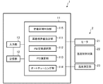
- FIG. 1 is a block diagram schematically illustrating a configuration of a temperature control device according to an embodiment of the present invention.
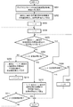
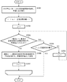
- 4 is a flowchart illustrating an outline of a processing operation of setting a section boundary value in the embodiment.
- 4 is a flowchart illustrating an outline of a processing operation of the auto tuning in the embodiment.
- 4 is a flowchart illustrating an outline of a processing operation of PID control in the embodiment.
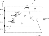
- Diagram showing an example of a program pattern Flowchart showing an outline of another example of the processing operation of setting the partition boundary value
- FIG. 1 is a block diagram schematically illustrating a configuration of a temperature control device according to an embodiment of the present invention.
- the temperature control device 1 of the present embodiment is a device for controlling the temperature of the control target 2, and here, an example will be described in which the temperature of the temperature control target 22 heated by the heater 21 is controlled.
- the temperature control device 1 controls the temperature of the control target 2 by PID control based on a program pattern in which a plurality of target values are set and a measurement value of the control target.
- the “measurement value of the control target” is temperature information of the temperature control target 22 measured by the temperature measurement unit 23.
- the temperature control device 1 includes an arithmetic unit 11, a storage unit 12, and an input unit 13 as a rough configuration.
- the operation unit 11 includes a constant value section determination unit 115 that determines a constant value section in which a target value included in the program pattern is kept at a constant value, and a section boundary that sets a value between target values of the constant value section as a section boundary value.
- the configuration is described separately for each function. However, it does not necessarily indicate that the configuration is divided into hardware.
- the arithmetic unit 11 may be a well-known device such as a PLC, an MCU, or a microcomputer.
- each component may be implemented as software. As described below, this embodiment exemplifies a configuration in which each component is implemented by software.
- each component may be configured as hardware, for example, may be configured using an FPGA or the like, or may be configured as dedicated hardware using an ASIC or the like.
- the storage unit 12 stores a program pattern set by a user and “PID constants corresponding to each section determined by a section boundary value” obtained by a process described below.
- the input unit 13 receives an input of a program pattern or the like set by the user, and includes, for example, an operation unit for the user to perform a setting operation, a receiving unit for receiving data input from an external device, and the like.
- the temperature control device 1 of the present embodiment controls the temperature of the control target 2 according to the set program pattern.
- FIG. 5 shows an example of the program pattern.
- FIG. 5 exemplifies a program pattern PP in which CV1 to CV7 are set as a constant value section in which the target temperature (target value) is kept constant.
- the temperature control device 1 controls the output of the heater 21 so that the temperature of the temperature control target 22 changes according to the program pattern PP.
- the control is performed by PID control based on a difference between a target value (target temperature) of the program pattern PP and a measured value obtained from the temperature measuring unit 23. In the PID control, an operation using a preset PID constant is performed. However, the entire control range indicated as “input range range” in FIG.
- the temperature control device 1 has features in the division of the section, the setting of the PID constant, and the PID control based on the division.
- the processing operation of the temperature control device 1 relating to the feature will be described with reference to the flowcharts of FIGS. 2 to 4 are executed by the arithmetic unit 11 while reading and writing data in the storage unit 12 as necessary. That is, here, the partition boundary value setting unit 111, the PID constant selection unit 112, the PID calculation unit 113, the auto tuning unit 114, and the fixed value section determination unit 115 are implemented as software.
- FIG. 2 is a flowchart showing an outline of a process of calculating and setting section boundary values (Th1 to Th3 in FIG. 5) serving as thresholds for dividing the control range into a plurality of sections.
- each target value is obtained from the program pattern PP set in the storage unit 12, a constant value section in which the target value is kept constant is obtained, and each constant value section is set to the target value. Sort in ascending order.
- the acquisition of the fixed value section is to determine a section in which the target value is kept constant for a predetermined period (that is, a section in which the slope in the program pattern PP is zero).
- the “predetermined period” may be arbitrarily determined based on a design concept. Based on the example of FIG.
- CV1 to CV7 are acquired as fixed-value sections, and are rearranged in the order of “fixed-value sections CV1, CV2, CV7, CV6, CV3, CV4, and CV5”. When there are a plurality of fixed value sections having the same target value, these are treated as one. In the present embodiment, an example in which the elements are arranged in ascending order is taken as an example.
- step 202 among the fixed-value sections sorted in step 201, the first and second fixed-value sections are acquired, and the average value of the target values of the first and second fixed-value sections is set as a section boundary value.
- Perform processing In the following processing, when the difference between the target values in the fixed-value section is equal to or larger than a predetermined value, the average value is set as the section boundary value. However, for the first and second fixed-value sections, the target value Regardless of the difference, the processing is set as the section boundary value. In the example of FIG. 5, the average value of the target temperatures of the fixed value sections CV1 and CV2 (an intermediate value between the target values of the fixed value sections CV1 and CV2) is set as the section boundary value Th1.
- step 202 the lower limit value of the control range (the input range range in FIG. 5) is treated as a fixed value section and the sorting process of step 201 is performed (the lower limit value of the control range becomes the first fixed value section).
- the processing described below may be executed.
- the same kind of purpose as in step 202 can be achieved.
- the processing from the smallest value is taken as an example, so the lower limit of the control range is treated as a fixed value section. It will be treated as a fixed value section.
- step 203 a process (initialization) of substituting 2 for a variable i is performed.
- the loop process of steps 204 to 211 following step 203 is a process for setting a section boundary value between target values (target temperatures) of each fixed value section.
- step 204 a process (initialization) of substituting 1 for a variable j is performed.
- the processing of steps 205 to 207 is processing for preventing the division of the section from becoming too fine.
- step 205 a process is performed to determine whether the difference between the target value of the i-th fixed-value section and the target value of the (i + j) -th fixed-value section is smaller than a predetermined value.
- the process is to compare the difference between the target temperature in the constant value section CV2 and the target temperature in the constant value section CV7 with a predetermined value.
- the “predetermined value” is a set value for preventing the division of the section from becoming too fine, and is set in advance and stored in the storage unit 12.
- the maximum value of the number of divisions (the maximum number of divisions) is determined, and the value obtained by dividing the control range (“input range range” in FIG. 5) by the maximum number of divisions is “predetermined value”.
- j is incremented, and the determination in step 205 is repeated.
- steps 205 to 207 is repeated until the interval between the target values becomes equal to or greater than a predetermined value.
- the process proceeds to step 208. That is, a pair of fixed value sections whose intervals are equal to or more than a predetermined value is determined by the repetitive processing of steps 205 to 207.
- the difference between the target temperatures in the constant value section CV2 and the constant value section CV7 is compared with a predetermined value.
- step 206 it is determined whether or not i + j has reached the number of fixed value sections, and if it has reached the “number of fixed value sections”, the processing exits from the loop and ends (step 206). : Yes ⁇ end).
- the process of step 206 ends the process when there is no i + j-th fixed-value section in which the difference between the target value and the i-th fixed-value section is larger than a predetermined value.
- the “number of fixed value sections” is the number of fixed value sections sorted in ascending order in step 201. That is, when there are a plurality of fixed value sections having the same target value, the value becomes smaller than the actual number of fixed value sections.
- step 208 it is determined whether or not i + j has reached the number of fixed-value sections (the same processing as in step 206). If "the number of sections" has been reached, the processing exits from the loop processing of steps 204 to 211 and proceeds to step 212.
- the storage unit 12 calculates the average value of the target value of the (i + j) -th fixed-value section and the target value of the i + (j + 1) -th constant-value section as the partition boundary value. Is performed.
- the (i + j) th fixed-value section is one of a pair of fixed-value sections obtained by the processing of steps 205 to 207 in which the interval between target values is equal to or greater than a predetermined value (the fixed-value section CV6 in the example of FIG. 5 described above).
- the i + (j + 1) -th constant value section is a constant value section having a target value next to the i + j-th constant value section (the constant value section CV3 in the example of FIG. 5 described above). That is, in the example of FIG. 5 described above, the average value of the target temperatures in the fixed value sections CV6 and CV3 is set as the section boundary value Th2. Note that the target value in the (i + j) th fixed-value section and the average value of the target values in the (i + (j + 1))-th fixed value section are the middle values of both target values.
- step 210 the variable i is set to the value of i + (j + 1), and in step 211, it is determined whether or not i has reached the number of fixed value sections. If i has not reached the number of fixed value sections, the process returns to step 204 and the above processing is repeated. If i has reached the number of fixed value sections, the processing ends. This is because when i reaches the number of fixed value sections, no further repetition (the processing of steps 204 to 211) is necessary.
- step 208 If the result of determination in step 208 is that the “number of fixed-value sections” has been reached, “a pair of fixed-value sections in which the interval between target values is equal to or greater than a predetermined value (i-th fixed-value section and i + j-th fixed-value section)” This means that there is no “fixed-value section having a target value next to the (i + j) -th fixed-value section”. In this case, the average value of the target value in the (i + j) -th fixed-value section and the target value in the (i + (j + 1))-th fixed-value section cannot be used as the partition boundary value (the processing in step 209).
- Step 212 is a process for setting a partition boundary value in such a case. If the result of determination in step 208 is that the “number of fixed-value sections” has been reached, the process proceeds to step 212, where the target value of the i + (j ⁇ 1) -th fixed-value section and the target value of the i + j-th fixed-value section A process of storing the average value in the storage unit 12 as a section boundary value is performed. When the process of step 212 is completed, the process ends. In the example of FIG.
- step 209 after the average value of the target temperatures of the fixed value sections CV6 and CV3 is set as the section boundary value Th2 (step 209), the processing proceeds to step 204 via steps 210 and 211, and the subsequent steps 205 to 207 In, a fixed value section CV5 having a difference equal to or more than a predetermined value from the fixed value section CV3 is determined, and the process proceeds to step 208.
- the determination result in step 208 is Yes, and the process proceeds to step 212, where the average value of the target temperatures in the fixed value sections CV4 and CV5 is set as the section boundary value Th3.
- an example is given in which the average value of the target value of the i + (j-1) th fixed-value section and the target value of the i + j-th fixed-value section is used as the section boundary value. Any value may be used as long as a value between the target value and the target value of the (i + j) th fixed-value section (in the example of FIG. 5, the fixed-value sections CV3 and CV5) is used as the section boundary value.
- the processing of FIG. 2 automatically sets a section boundary value for dividing the control range into a plurality of sections. That is, the setting of the division is automatically performed. Further, the processing of steps 204 to 211 suppresses the setting of the partition boundary value within the range of the “predetermined value”, so that the division of the partition is prevented from becoming too fine.
- a corresponding PID constant is set for each of the divided sections, and a PID constant suitable for the temperature situation of the control target is used. The processing becomes inefficient, for example, the PID constants are set finely and the PID constants are uselessly switched in the PID control. However, the above processing suppresses the problem.
- the “predetermined value” an example using a value obtained by dividing the control range by the maximum number of divisions is used.
- the minimum value (division minimum width) as the division width is used. May be set as a “predetermined value”.
- the range boundary is set to the section boundary. The processing may be performed so that the value is not set. In this case, a range in which the section boundary value is not set may be set in advance, and if the target value is within the range, the process may skip step 209 or step 212.
- the section is determined by the section boundary value obtained by the processing of FIG. 2 described above.
- sections 1 to 4 are defined by section boundary values Th1 to Th3.
- the process of FIG. 3 is a process in which the processes of steps 301 to 304 are repeatedly executed for all the partitions in order.
- an example in which the sections are processed in ascending order in order from a section having a lower temperature to a section having a higher temperature
- the order is excellent in efficiency.
- the control target cools down, it is preferable to set the processing order in descending order, and the processing order may be set according to each control target.
- steps 301 and 302 is processing for determining a target value used for automatic tuning for automatically calculating a PID constant.
- step 301 it is determined whether or not a plurality of fixed value sections are included in the section. According to the example of FIG. 5, since there is only one fixed value section CV1 in the first section 1, the process skips step 302 and shifts to step 303 (step 301: Yes ⁇ step 303).
- step 301: No ⁇ Step 302 a process of acquiring a target value closest to the value of the center of the section is performed among the fixed value sections included in the section.
- the processing is to provide a width equal to or more than a predetermined value in the section, so that a plurality of fixed value sections may be included in the section. is there.
- the processing of steps 301 and 302 sets the target value used for auto tuning to the target value of the fixed-value section having the target value closest to the value at the center of the section.
- the PID constant when the PID constant is optimized for the target value near the lower limit of the section, if this is used in the PID control for the target value near the upper limit of the section, the PID constant may not be appropriate for the control target. There is also. Such a problem can be reduced by setting the target value used for auto-tuning to be the target value of the fixed-value section having the target value closest to the value at the center of the section.
- a PID constant is automatically calculated by auto-tuning using the target value of the fixed section included in the section (if there are a plurality of sections, the target value closest to the center value of the section).
- the target value of the fixed section included in the section if there are a plurality of sections, the target value closest to the center value of the section.
- any available auto tuning can be used. Since the auto-tuning function itself is not directly related to the present invention, the description thereof is omitted here.
- step 304 the PID constant obtained in step 303 is stored in the storage unit 12 in association with the corresponding section.
- step 401 a process is performed to determine to which partition the temperature of the temperature control target 22 measured by the temperature measuring unit 23 belongs, and to acquire a PID constant corresponding to the partition from the storage unit 12.
- step 402 using the obtained PID constant, a PID calculation is performed based on the difference between the program pattern (target temperature) and the measured temperature of the temperature control target 22 obtained by the temperature measuring unit 23. The output of the heater 21 is controlled based on the operated amount.
- Step 403 Yes ⁇ Step 401.
- PID control using the PID constant set for each section is performed.
- the setting of the division of the control range is automatically performed, and the calculation and the setting of the PID constant corresponding to each of the sections are automatically performed. Therefore, the setting operation can be further simplified.
- FIG. 6 shows another example of a process of calculating and setting a section boundary value serving as a threshold for dividing the control range into a plurality of sections.
- the processing in FIG. 6 is different from the processing in FIG. 2 in step 209 ′ and step 212 ′.
- step 209 ′ in FIG. 6 the average value of the target values in the i-th and i + (j + 1) -th fixed value sections is calculated, and the average value is set as the section boundary value.
- the i-th constant value section is CV2
- CV6 is acquired as a pair with CV2
- the average of the target values of CV6 and CV3 is defined as the section boundary.
- the i-th fixed-value section is CV2
- the CV6 is acquired as a pair with the CV2, but this is the same, but the target value of CV2 and CV3 is The average is set as the section boundary value.
- Step 212 'in FIG. 6 has the same meaning, and is a process in which the average value of the target values of the i-th and (i + j) -th fixed value sections is set as the section boundary value.
- the i-th fixed-value section is CV3, CV5 is acquired as a pair with CV3, and the average of the target values of CV4 and CV5 is defined as the section boundary. Set as a value.
- the CV5 is acquired as a pair with the CV3. The average is set as the section boundary value.
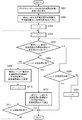
- FIG. 7 shows still another example of a process of calculating and setting a section boundary value serving as a threshold for dividing the control range into a plurality of sections.
- Step 701 is the same as step 201 in FIG.
- the loop processing subsequent to step 701 is processing for setting a section boundary value between target values (target temperatures) of each fixed value section.
- step 702 a process (initialization) of substituting 1 for a variable j is performed. It should be noted that although simplified in the figure, 1 is substituted for the variable i, and the processing of steps 702 to 707 in the loop is repeated until i becomes “the number of fixed-value sections ⁇ 1”.
- Steps 703 to 705 are the same as steps 205 to 207 in FIG.
- step 706 the average value of the target values of the i-th fixed-value section and the (i + j) -th fixed-value section, which are pairs of fixed-value sections in which the target value intervals are equal to or greater than the predetermined value, obtained by the processing of steps 703 to 705 I do.
- the calculated average value is stored in the storage unit 12 as a section boundary value. That is, a value (here, an average value) between the target values of adjacent fixed value sections when the fixed value sections are arranged in descending order of their target values is set as a section boundary value.
- the average value of these target temperatures is set as the section boundary value Th1.
- step 707 the variable i is set to the value of i + j.
- steps 702 to 707 are repeated until i becomes “the number of fixed value sections ⁇ 1”, and the process ends when the processing with “the number of fixed value sections ⁇ 1” ends.
- the temperature control device is described as an example of the control device.
- the present invention is not limited to this.
- Various types of PID control based on a program pattern in which a plurality of target values are set are described. Can be applied to the control device.
- the processing of setting the average value of the two target values as the section boundary value is performed.
- a configuration may be used in which a value between two target values is automatically generated at random and set as a partition boundary value, or a partition boundary value is set based on preset ratio information.
- the “preset ratio information” is information that is preset in the apparatus as a default or that is set by the user.
- the ratio information is, for example, information such as 60%, and a section boundary value is provided so as to be at a position of 60% between two target values.
- the present embodiment has the same result as the case where 50% is set as the ratio information.
- the default of the apparatus may be set to 50% (the same operation as in the present embodiment), and when the user sets the ratio information, the apparatus may be operated according to the setting.
- the apparatus by setting the average value of the two target values as the partition boundary value (the same as setting the ratio information to 50%), unnecessary switching of PID constants is reduced, and processing efficiency is reduced. Excellent in nature.
- the section boundary value Th2 when the section boundary value Th2 is set to a value close to CV1, the temperature temporarily exceeds the section boundary value Th2 due to an overshoot generated when the temperature is controlled to CV1.
- the switching of the PID constant may occur a plurality of times.
- the section boundary value Th2 when the section boundary value Th2 is set to a value close to CV2, switching of the PID constant may occur a plurality of times due to an undershoot generated when performing temperature control on CV2.
- the occurrence of such a phenomenon can be reduced.
- the overshoot In the control for increasing the temperature, the overshoot is usually larger than the undershoot. Therefore, a value slightly offset from the average value of the two target values may be set as the section boundary value.
- the “slightly offset value” may be a value obtained by actually measuring the values of the overshoot and the undershoot and offsetting the difference by a difference, or a predetermined value (for example, “5% of the width of the section”). The value may be offset by a predetermined value).
- the heating target as a control target that is, the target value basically changes from a low target value to a high target value, so that each constant value section is sorted in ascending order of the target value.
- the processes are performed in ascending order of the target value, but the present invention is not limited to this.
- the difference between the ascending order and the descending order and the difference in the processing order do not give a difference to the concept of the invention, but can be appropriately selected.
- the fixed value sections are arranged in ascending order of their target values in the same manner as in the present embodiment, and the processing in steps 203 to 212 is performed for the one with the larger i (“the fixed value section”). From the number “)”, processing may be performed while decrementing i.
- the “fixed-value section having a target value next to the fixed-value section CV4 in FIG. 5” is the fixed-value section CV3.
Landscapes
- Engineering & Computer Science (AREA)
- Physics & Mathematics (AREA)
- General Physics & Mathematics (AREA)
- Automation & Control Theory (AREA)
- Health & Medical Sciences (AREA)
- Artificial Intelligence (AREA)
- Computer Vision & Pattern Recognition (AREA)
- Evolutionary Computation (AREA)
- Medical Informatics (AREA)
- Software Systems (AREA)
- Feedback Control In General (AREA)
Abstract
La présente invention concerne un dispositif de commande qui effectue le calcul d'une quantité d'opérations selon un calcul PID sur la base d'un motif de programme pour lequel une pluralité de valeurs cibles d'un objet de commande sont définies, et d'une valeur de mesure de l'objet de commande, le dispositif de commande comprenant : une unité de définition de valeur limite de partition (111) qui définit en tant que valeur limite de partition une valeur qui est entre des valeurs cibles adjacentes lorsqu'une pluralité de valeurs cibles incluses dans le motif de programme sont alignées par ordre de taille ; une unité de stockage (12) dans laquelle sont stockées des constantes PID correspondant à chaque partition déterminée par la valeur limite de partition ; une unité de sélection de constante PID (112) qui détermine à laquelle parmi les partitions la valeur de mesure de l'objet de commande correspond, et sélectionne la constante PID associée à cette partition déterminée ; et une unité de calcul PID (114) qui effectue un traitement de calcul de la quantité d'opérations par calcul PID à l'aide de la constante PID sélectionnée par l'unité de sélection de constante PID (112).
Priority Applications (2)
| Application Number | Priority Date | Filing Date | Title |
|---|---|---|---|
| PCT/JP2018/025314 WO2020008548A1 (fr) | 2018-07-04 | 2018-07-04 | Dispositif de commande et programme de commande |
| JP2020528589A JP6967712B2 (ja) | 2018-07-04 | 2018-07-04 | 制御装置及び制御プログラム |
Applications Claiming Priority (1)
| Application Number | Priority Date | Filing Date | Title |
|---|---|---|---|
| PCT/JP2018/025314 WO2020008548A1 (fr) | 2018-07-04 | 2018-07-04 | Dispositif de commande et programme de commande |
Publications (1)
| Publication Number | Publication Date |
|---|---|
| WO2020008548A1 true WO2020008548A1 (fr) | 2020-01-09 |
Family
ID=69060472
Family Applications (1)
| Application Number | Title | Priority Date | Filing Date |
|---|---|---|---|
| PCT/JP2018/025314 Ceased WO2020008548A1 (fr) | 2018-07-04 | 2018-07-04 | Dispositif de commande et programme de commande |
Country Status (2)
| Country | Link |
|---|---|
| JP (1) | JP6967712B2 (fr) |
| WO (1) | WO2020008548A1 (fr) |
Cited By (1)
| Publication number | Priority date | Publication date | Assignee | Title |
|---|---|---|---|---|
| CN117142540A (zh) * | 2023-09-05 | 2023-12-01 | 上海米勒缘生物科技有限公司 | 一种富氢水发生器的进水量控制方法及系统 |
Citations (3)
| Publication number | Priority date | Publication date | Assignee | Title |
|---|---|---|---|---|
| JPS6270904A (ja) * | 1985-09-24 | 1987-04-01 | Nissei Plastics Ind Co | 温度制御方法 |
| JPH03268105A (ja) * | 1990-03-19 | 1991-11-28 | Rika Kogyo Kk | プログラム調節計 |
| JPH1011114A (ja) * | 1996-06-19 | 1998-01-16 | Rika Kogyo Kk | プログラム調節計における記憶領域設定装置 |
-
2018
- 2018-07-04 WO PCT/JP2018/025314 patent/WO2020008548A1/fr not_active Ceased
- 2018-07-04 JP JP2020528589A patent/JP6967712B2/ja active Active
Patent Citations (3)
| Publication number | Priority date | Publication date | Assignee | Title |
|---|---|---|---|---|
| JPS6270904A (ja) * | 1985-09-24 | 1987-04-01 | Nissei Plastics Ind Co | 温度制御方法 |
| JPH03268105A (ja) * | 1990-03-19 | 1991-11-28 | Rika Kogyo Kk | プログラム調節計 |
| JPH1011114A (ja) * | 1996-06-19 | 1998-01-16 | Rika Kogyo Kk | プログラム調節計における記憶領域設定装置 |
Cited By (1)
| Publication number | Priority date | Publication date | Assignee | Title |
|---|---|---|---|---|
| CN117142540A (zh) * | 2023-09-05 | 2023-12-01 | 上海米勒缘生物科技有限公司 | 一种富氢水发生器的进水量控制方法及系统 |
Also Published As
| Publication number | Publication date |
|---|---|
| JP6967712B2 (ja) | 2021-11-17 |
| JPWO2020008548A1 (ja) | 2021-02-18 |
Similar Documents
| Publication | Publication Date | Title |
|---|---|---|
| Gialamas et al. | Reheating in R 2 Palatini inflationary models | |
| CN108790696B (zh) | 温度控制方法、装置、电子设备及存储介质 | |
| JP2020513120A5 (fr) | ||
| WO2020008548A1 (fr) | Dispositif de commande et programme de commande | |
| CN106200549B (zh) | 管理加工数据和加工结果的数值控制装置 | |
| CN113687669A (zh) | 用于调节干燥箱温度方法、装置、干燥箱及存储介质 | |
| CN113917959B (zh) | 一种基于控制调节器的温度控制方法、装置及电子设备 | |
| EP4060431A1 (fr) | Organe de commande, procédé et programme de commande | |
| JP2012089004A (ja) | オートチューニング装置及びオートチューニング方法 | |
| US10622927B2 (en) | Parameter selection support system, parameter selection support method, and parameter selection support program | |
| JPH0736504A (ja) | Pid制御装置の制御定数調整装置 | |
| JP6493904B2 (ja) | パラメータ選定方法、パラメータ選定プログラム及びパラメータ選定装置 | |
| KR0142262B1 (ko) | 자동 고휘도 압축회로 | |
| KR102610186B1 (ko) | 멀티 모델 및 점진적 배치를 이용한 학습률 결정 장치 및 방법 | |
| JP7555429B2 (ja) | 学習率がニアゼロである場合の勾配降下法 | |
| US20210072724A1 (en) | Controller | |
| KR102570818B1 (ko) | 전력 제어 장치, 전력 공급의 할당 방법 | |
| KR20160044221A (ko) | 용접변형에 대한 수정비용 산출시스템 및 방법 | |
| JP5900442B2 (ja) | 切り出し装置及び切り出し方法 | |
| JP2839679B2 (ja) | 制御パラメータのオートチューニング装置 | |
| JP2020034969A (ja) | 制御装置および制御方法 | |
| Minjárez-Sosa | Empirical estimation in average Markov control processes | |
| JP2847313B2 (ja) | プログラム調節計 | |
| JP2008257625A (ja) | 位相制御方法および位相制御装置 | |
| WO2019106782A1 (fr) | Dispositif et procédé de commande de pid |
Legal Events
| Date | Code | Title | Description |
|---|---|---|---|
| 121 | Ep: the epo has been informed by wipo that ep was designated in this application |
Ref document number: 18925089 Country of ref document: EP Kind code of ref document: A1 |
|
| ENP | Entry into the national phase |
Ref document number: 2020528589 Country of ref document: JP Kind code of ref document: A |
|
| NENP | Non-entry into the national phase |
Ref country code: DE |
|
| 122 | Ep: pct application non-entry in european phase |
Ref document number: 18925089 Country of ref document: EP Kind code of ref document: A1 |