WO2020008548A1 - 制御装置及び制御プログラム - Google Patents
制御装置及び制御プログラム Download PDFInfo
- Publication number
- WO2020008548A1 WO2020008548A1 PCT/JP2018/025314 JP2018025314W WO2020008548A1 WO 2020008548 A1 WO2020008548 A1 WO 2020008548A1 JP 2018025314 W JP2018025314 W JP 2018025314W WO 2020008548 A1 WO2020008548 A1 WO 2020008548A1
- Authority
- WO
- WIPO (PCT)
- Prior art keywords
- value
- section
- fixed
- target
- sections
- Prior art date
- Legal status (The legal status is an assumption and is not a legal conclusion. Google has not performed a legal analysis and makes no representation as to the accuracy of the status listed.)
- Ceased
Links
Images



Classifications
-
- G—PHYSICS
- G05—CONTROLLING; REGULATING
- G05B—CONTROL OR REGULATING SYSTEMS IN GENERAL; FUNCTIONAL ELEMENTS OF SUCH SYSTEMS; MONITORING OR TESTING ARRANGEMENTS FOR SUCH SYSTEMS OR ELEMENTS
- G05B13/00—Adaptive control systems, i.e. systems automatically adjusting themselves to have a performance which is optimum according to some preassigned criterion
- G05B13/02—Adaptive control systems, i.e. systems automatically adjusting themselves to have a performance which is optimum according to some preassigned criterion electric
-
- G—PHYSICS
- G05—CONTROLLING; REGULATING
- G05B—CONTROL OR REGULATING SYSTEMS IN GENERAL; FUNCTIONAL ELEMENTS OF SUCH SYSTEMS; MONITORING OR TESTING ARRANGEMENTS FOR SUCH SYSTEMS OR ELEMENTS
- G05B19/00—Program-control systems
- G05B19/02—Program-control systems electric
Definitions
- the present invention relates to a control device and a control program for calculating an operation amount by PID calculation.
- PID control is widely used in control of various control targets (for example, temperature control of a heater, etc.).
- a PID constant according to the characteristics of the control target is set and used.
- the characteristics of the control target change according to the control range, it is desirable that the PID constant be optimized accordingly.
- Patent Document 1 A conventional technique related to such PID control is disclosed in Patent Document 1.
- Patent Document 1 a control range is divided into a plurality of sections in advance, and a PID constant corresponding to each section is set by auto tuning. Thus, when performing PID control based on a program pattern in which a plurality of target values to be controlled are set, a PID constant corresponding to each section is selected. According to Patent Document 1, there is no need to set a PID for each step of a program pattern, and the burden on the user can be reduced. However, the setting operation of dividing the control range into a plurality of sections needs to be performed by the user, and is complicated in this respect.
- the present invention is a control device and a control program for dividing a control range into a plurality of sections and performing PID control using different PID constants for each section, and further simplifies a setting operation. It is an object of the present invention to provide a control device and a control program which achieves the above.
- a control device for calculating an operation amount by PID calculation based on a program pattern in which a plurality of target values of a control target are set and a measurement value of the control target, wherein the target value included in the program pattern is a constant value.
- a fixed-value section determining unit for determining a fixed-value section that is kept at a predetermined value; and a partition boundary that sets a value between target values of adjacent fixed-value sections when the fixed-value sections are arranged in descending order of their target values as a block boundary value.
- a value setting unit a storage unit storing a PID constant corresponding to each section defined by the section boundary value, and discriminating which of the sections the measured value of the control target corresponds to, Using the PID constant selection unit that selects the PID constant associated with the divided section and the PID constant selected by the PID constant selection unit, Control apparatus characterized by comprising: a PID arithmetic unit that performs output processing, the.
- Configuration 2 The control device according to Configuration 1, wherein in the setting processing of the partition boundary value, the partition boundary value is set between target values of the adjacent fixed-value sections based on preset ratio information. .
- a control device for calculating an operation amount by PID calculation based on a program pattern in which a plurality of target values of a control target are set and a measurement value of the control target, wherein the target value included in the program pattern is a constant value.
- a fixed-value section discriminator that determines a fixed-value section that is kept at a predetermined value, and a difference between target values of the fixed-value sections when the fixed-value sections are arranged in descending order of their target values.
- a section boundary value setting unit that acquires a second fixed-value section having a next target value, and sets a value between the target values of the acquired first and second fixed-value sections as a section boundary value;
- a storage unit in which a PID constant corresponding to each section to be determined, the maximum number of section divisions or the minimum section width is stored, and which of the sections the measurement value of the control target corresponds to is determined. Then, using the PID constant selection unit that selects the PID constant associated with the determined section and the PID constant selected by the PID constant selection unit, the operation amount calculation processing by the PID calculation is performed.
- a control device comprising: a PID calculation unit.
- a fixed-value section discriminator that determines a fixed-value section that is kept at a predetermined value, and a difference between target values of the fixed-value sections when the fixed-value sections are arranged in descending order of their target values. Two fixed-value sections that are a combination of a value divided by a number or a combination larger than the minimum section width are determined, and a first fixed-value section, which is one of the two fixed-value sections, and a fixed-value section of the two fixed-value sections.
- a second fixed-value section having a target value next to the other fixed-value section, and setting a value between the obtained target values of the first and second fixed-value sections as a section boundary value.
- Department and A storage unit that stores a PID constant corresponding to each section defined by the section boundary value, the maximum number of section divisions or the minimum section width, and a measurement value of the control target corresponding to any of the sections.
- a PID constant selecting unit for determining whether the PID constant is associated with the determined section, and a PID constant using the PID constant selected by the PID constant selecting unit.
- a PID calculation unit for performing a calculation process of (1).
- (Configuration 11) 11 The apparatus according to claim 1, further comprising: an auto-tuning unit that calculates a PID constant corresponding to the section by performing auto-tuning using the target value existing in the section. Control device.
- the first fixed-value section which is one of the fixed-value sections of the two fixed-value sections, is determined by determining two fixed-value sections having a value greater than the value divided by the maximum number or the section minimum width, and the first fixed-value section. Acquiring a second fixed-value section having a target value next to the target value, and setting a value between the obtained target values of the first and second fixed-value sections as a section boundary value; It is determined which of the sections defined by the section boundary value corresponds to the measured value, and from the storage unit in which the PID constant corresponding to each section is stored, the measured value is associated with the determined section. Acquiring the PID constant, and performing a process of calculating an operation amount by PID calculation using the acquired PID constant.
- Two fixed-value sections that are a combination of a value greater than the value divided by the maximum number or a section minimum width are determined, and a first fixed-value section that is one of the two fixed-value sections and a fixed-value section of the two fixed-value sections are determined.
- a second fixed-value section having a target value next to the other fixed-value section in the set, and setting a value between the obtained target values of the first and second fixed-value sections as a section boundary value.
- the measured value of the control object corresponds to each of the sections defined by the section boundary value, and from the storage unit in which the PID constant corresponding to each section is stored, Acquiring the PID constant associated with the divided section, and performing a process of calculating an operation amount by PID calculation using the acquired PID constant. program.
- the section boundary value for dividing the control range into a plurality of sections is automatically set. Therefore, in PID control using a different PID constant for each section, the setting work Further simplification is achieved.
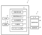
- FIG. 1 is a block diagram schematically illustrating a configuration of a temperature control device according to an embodiment of the present invention.
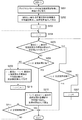
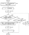
- 4 is a flowchart illustrating an outline of a processing operation of setting a section boundary value in the embodiment.
- 4 is a flowchart illustrating an outline of a processing operation of the auto tuning in the embodiment.
- 4 is a flowchart illustrating an outline of a processing operation of PID control in the embodiment.
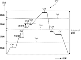
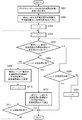
- Diagram showing an example of a program pattern Flowchart showing an outline of another example of the processing operation of setting the partition boundary value
- FIG. 1 is a block diagram schematically illustrating a configuration of a temperature control device according to an embodiment of the present invention.
- the temperature control device 1 of the present embodiment is a device for controlling the temperature of the control target 2, and here, an example will be described in which the temperature of the temperature control target 22 heated by the heater 21 is controlled.
- the temperature control device 1 controls the temperature of the control target 2 by PID control based on a program pattern in which a plurality of target values are set and a measurement value of the control target.
- the “measurement value of the control target” is temperature information of the temperature control target 22 measured by the temperature measurement unit 23.
- the temperature control device 1 includes an arithmetic unit 11, a storage unit 12, and an input unit 13 as a rough configuration.
- the operation unit 11 includes a constant value section determination unit 115 that determines a constant value section in which a target value included in the program pattern is kept at a constant value, and a section boundary that sets a value between target values of the constant value section as a section boundary value.
- the configuration is described separately for each function. However, it does not necessarily indicate that the configuration is divided into hardware.
- the arithmetic unit 11 may be a well-known device such as a PLC, an MCU, or a microcomputer.
- each component may be implemented as software. As described below, this embodiment exemplifies a configuration in which each component is implemented by software.
- each component may be configured as hardware, for example, may be configured using an FPGA or the like, or may be configured as dedicated hardware using an ASIC or the like.
- the storage unit 12 stores a program pattern set by a user and “PID constants corresponding to each section determined by a section boundary value” obtained by a process described below.
- the input unit 13 receives an input of a program pattern or the like set by the user, and includes, for example, an operation unit for the user to perform a setting operation, a receiving unit for receiving data input from an external device, and the like.
- the temperature control device 1 of the present embodiment controls the temperature of the control target 2 according to the set program pattern.
- FIG. 5 shows an example of the program pattern.
- FIG. 5 exemplifies a program pattern PP in which CV1 to CV7 are set as a constant value section in which the target temperature (target value) is kept constant.
- the temperature control device 1 controls the output of the heater 21 so that the temperature of the temperature control target 22 changes according to the program pattern PP.
- the control is performed by PID control based on a difference between a target value (target temperature) of the program pattern PP and a measured value obtained from the temperature measuring unit 23. In the PID control, an operation using a preset PID constant is performed. However, the entire control range indicated as “input range range” in FIG.
- the temperature control device 1 has features in the division of the section, the setting of the PID constant, and the PID control based on the division.
- the processing operation of the temperature control device 1 relating to the feature will be described with reference to the flowcharts of FIGS. 2 to 4 are executed by the arithmetic unit 11 while reading and writing data in the storage unit 12 as necessary. That is, here, the partition boundary value setting unit 111, the PID constant selection unit 112, the PID calculation unit 113, the auto tuning unit 114, and the fixed value section determination unit 115 are implemented as software.
- FIG. 2 is a flowchart showing an outline of a process of calculating and setting section boundary values (Th1 to Th3 in FIG. 5) serving as thresholds for dividing the control range into a plurality of sections.
- each target value is obtained from the program pattern PP set in the storage unit 12, a constant value section in which the target value is kept constant is obtained, and each constant value section is set to the target value. Sort in ascending order.
- the acquisition of the fixed value section is to determine a section in which the target value is kept constant for a predetermined period (that is, a section in which the slope in the program pattern PP is zero).
- the “predetermined period” may be arbitrarily determined based on a design concept. Based on the example of FIG.
- CV1 to CV7 are acquired as fixed-value sections, and are rearranged in the order of “fixed-value sections CV1, CV2, CV7, CV6, CV3, CV4, and CV5”. When there are a plurality of fixed value sections having the same target value, these are treated as one. In the present embodiment, an example in which the elements are arranged in ascending order is taken as an example.
- step 202 among the fixed-value sections sorted in step 201, the first and second fixed-value sections are acquired, and the average value of the target values of the first and second fixed-value sections is set as a section boundary value.
- Perform processing In the following processing, when the difference between the target values in the fixed-value section is equal to or larger than a predetermined value, the average value is set as the section boundary value. However, for the first and second fixed-value sections, the target value Regardless of the difference, the processing is set as the section boundary value. In the example of FIG. 5, the average value of the target temperatures of the fixed value sections CV1 and CV2 (an intermediate value between the target values of the fixed value sections CV1 and CV2) is set as the section boundary value Th1.
- step 202 the lower limit value of the control range (the input range range in FIG. 5) is treated as a fixed value section and the sorting process of step 201 is performed (the lower limit value of the control range becomes the first fixed value section).
- the processing described below may be executed.
- the same kind of purpose as in step 202 can be achieved.
- the processing from the smallest value is taken as an example, so the lower limit of the control range is treated as a fixed value section. It will be treated as a fixed value section.
- step 203 a process (initialization) of substituting 2 for a variable i is performed.
- the loop process of steps 204 to 211 following step 203 is a process for setting a section boundary value between target values (target temperatures) of each fixed value section.
- step 204 a process (initialization) of substituting 1 for a variable j is performed.
- the processing of steps 205 to 207 is processing for preventing the division of the section from becoming too fine.
- step 205 a process is performed to determine whether the difference between the target value of the i-th fixed-value section and the target value of the (i + j) -th fixed-value section is smaller than a predetermined value.
- the process is to compare the difference between the target temperature in the constant value section CV2 and the target temperature in the constant value section CV7 with a predetermined value.
- the “predetermined value” is a set value for preventing the division of the section from becoming too fine, and is set in advance and stored in the storage unit 12.
- the maximum value of the number of divisions (the maximum number of divisions) is determined, and the value obtained by dividing the control range (“input range range” in FIG. 5) by the maximum number of divisions is “predetermined value”.
- j is incremented, and the determination in step 205 is repeated.
- steps 205 to 207 is repeated until the interval between the target values becomes equal to or greater than a predetermined value.
- the process proceeds to step 208. That is, a pair of fixed value sections whose intervals are equal to or more than a predetermined value is determined by the repetitive processing of steps 205 to 207.
- the difference between the target temperatures in the constant value section CV2 and the constant value section CV7 is compared with a predetermined value.
- step 206 it is determined whether or not i + j has reached the number of fixed value sections, and if it has reached the “number of fixed value sections”, the processing exits from the loop and ends (step 206). : Yes ⁇ end).
- the process of step 206 ends the process when there is no i + j-th fixed-value section in which the difference between the target value and the i-th fixed-value section is larger than a predetermined value.
- the “number of fixed value sections” is the number of fixed value sections sorted in ascending order in step 201. That is, when there are a plurality of fixed value sections having the same target value, the value becomes smaller than the actual number of fixed value sections.
- step 208 it is determined whether or not i + j has reached the number of fixed-value sections (the same processing as in step 206). If "the number of sections" has been reached, the processing exits from the loop processing of steps 204 to 211 and proceeds to step 212.
- the storage unit 12 calculates the average value of the target value of the (i + j) -th fixed-value section and the target value of the i + (j + 1) -th constant-value section as the partition boundary value. Is performed.
- the (i + j) th fixed-value section is one of a pair of fixed-value sections obtained by the processing of steps 205 to 207 in which the interval between target values is equal to or greater than a predetermined value (the fixed-value section CV6 in the example of FIG. 5 described above).
- the i + (j + 1) -th constant value section is a constant value section having a target value next to the i + j-th constant value section (the constant value section CV3 in the example of FIG. 5 described above). That is, in the example of FIG. 5 described above, the average value of the target temperatures in the fixed value sections CV6 and CV3 is set as the section boundary value Th2. Note that the target value in the (i + j) th fixed-value section and the average value of the target values in the (i + (j + 1))-th fixed value section are the middle values of both target values.
- step 210 the variable i is set to the value of i + (j + 1), and in step 211, it is determined whether or not i has reached the number of fixed value sections. If i has not reached the number of fixed value sections, the process returns to step 204 and the above processing is repeated. If i has reached the number of fixed value sections, the processing ends. This is because when i reaches the number of fixed value sections, no further repetition (the processing of steps 204 to 211) is necessary.
- step 208 If the result of determination in step 208 is that the “number of fixed-value sections” has been reached, “a pair of fixed-value sections in which the interval between target values is equal to or greater than a predetermined value (i-th fixed-value section and i + j-th fixed-value section)” This means that there is no “fixed-value section having a target value next to the (i + j) -th fixed-value section”. In this case, the average value of the target value in the (i + j) -th fixed-value section and the target value in the (i + (j + 1))-th fixed-value section cannot be used as the partition boundary value (the processing in step 209).
- Step 212 is a process for setting a partition boundary value in such a case. If the result of determination in step 208 is that the “number of fixed-value sections” has been reached, the process proceeds to step 212, where the target value of the i + (j ⁇ 1) -th fixed-value section and the target value of the i + j-th fixed-value section A process of storing the average value in the storage unit 12 as a section boundary value is performed. When the process of step 212 is completed, the process ends. In the example of FIG.
- step 209 after the average value of the target temperatures of the fixed value sections CV6 and CV3 is set as the section boundary value Th2 (step 209), the processing proceeds to step 204 via steps 210 and 211, and the subsequent steps 205 to 207 In, a fixed value section CV5 having a difference equal to or more than a predetermined value from the fixed value section CV3 is determined, and the process proceeds to step 208.
- the determination result in step 208 is Yes, and the process proceeds to step 212, where the average value of the target temperatures in the fixed value sections CV4 and CV5 is set as the section boundary value Th3.
- an example is given in which the average value of the target value of the i + (j-1) th fixed-value section and the target value of the i + j-th fixed-value section is used as the section boundary value. Any value may be used as long as a value between the target value and the target value of the (i + j) th fixed-value section (in the example of FIG. 5, the fixed-value sections CV3 and CV5) is used as the section boundary value.
- the processing of FIG. 2 automatically sets a section boundary value for dividing the control range into a plurality of sections. That is, the setting of the division is automatically performed. Further, the processing of steps 204 to 211 suppresses the setting of the partition boundary value within the range of the “predetermined value”, so that the division of the partition is prevented from becoming too fine.
- a corresponding PID constant is set for each of the divided sections, and a PID constant suitable for the temperature situation of the control target is used. The processing becomes inefficient, for example, the PID constants are set finely and the PID constants are uselessly switched in the PID control. However, the above processing suppresses the problem.
- the “predetermined value” an example using a value obtained by dividing the control range by the maximum number of divisions is used.
- the minimum value (division minimum width) as the division width is used. May be set as a “predetermined value”.
- the range boundary is set to the section boundary. The processing may be performed so that the value is not set. In this case, a range in which the section boundary value is not set may be set in advance, and if the target value is within the range, the process may skip step 209 or step 212.
- the section is determined by the section boundary value obtained by the processing of FIG. 2 described above.
- sections 1 to 4 are defined by section boundary values Th1 to Th3.
- the process of FIG. 3 is a process in which the processes of steps 301 to 304 are repeatedly executed for all the partitions in order.
- an example in which the sections are processed in ascending order in order from a section having a lower temperature to a section having a higher temperature
- the order is excellent in efficiency.
- the control target cools down, it is preferable to set the processing order in descending order, and the processing order may be set according to each control target.
- steps 301 and 302 is processing for determining a target value used for automatic tuning for automatically calculating a PID constant.
- step 301 it is determined whether or not a plurality of fixed value sections are included in the section. According to the example of FIG. 5, since there is only one fixed value section CV1 in the first section 1, the process skips step 302 and shifts to step 303 (step 301: Yes ⁇ step 303).
- step 301: No ⁇ Step 302 a process of acquiring a target value closest to the value of the center of the section is performed among the fixed value sections included in the section.
- the processing is to provide a width equal to or more than a predetermined value in the section, so that a plurality of fixed value sections may be included in the section. is there.
- the processing of steps 301 and 302 sets the target value used for auto tuning to the target value of the fixed-value section having the target value closest to the value at the center of the section.
- the PID constant when the PID constant is optimized for the target value near the lower limit of the section, if this is used in the PID control for the target value near the upper limit of the section, the PID constant may not be appropriate for the control target. There is also. Such a problem can be reduced by setting the target value used for auto-tuning to be the target value of the fixed-value section having the target value closest to the value at the center of the section.
- a PID constant is automatically calculated by auto-tuning using the target value of the fixed section included in the section (if there are a plurality of sections, the target value closest to the center value of the section).
- the target value of the fixed section included in the section if there are a plurality of sections, the target value closest to the center value of the section.
- any available auto tuning can be used. Since the auto-tuning function itself is not directly related to the present invention, the description thereof is omitted here.
- step 304 the PID constant obtained in step 303 is stored in the storage unit 12 in association with the corresponding section.
- step 401 a process is performed to determine to which partition the temperature of the temperature control target 22 measured by the temperature measuring unit 23 belongs, and to acquire a PID constant corresponding to the partition from the storage unit 12.
- step 402 using the obtained PID constant, a PID calculation is performed based on the difference between the program pattern (target temperature) and the measured temperature of the temperature control target 22 obtained by the temperature measuring unit 23. The output of the heater 21 is controlled based on the operated amount.
- Step 403 Yes ⁇ Step 401.
- PID control using the PID constant set for each section is performed.
- the setting of the division of the control range is automatically performed, and the calculation and the setting of the PID constant corresponding to each of the sections are automatically performed. Therefore, the setting operation can be further simplified.
- FIG. 6 shows another example of a process of calculating and setting a section boundary value serving as a threshold for dividing the control range into a plurality of sections.
- the processing in FIG. 6 is different from the processing in FIG. 2 in step 209 ′ and step 212 ′.
- step 209 ′ in FIG. 6 the average value of the target values in the i-th and i + (j + 1) -th fixed value sections is calculated, and the average value is set as the section boundary value.
- the i-th constant value section is CV2
- CV6 is acquired as a pair with CV2
- the average of the target values of CV6 and CV3 is defined as the section boundary.
- the i-th fixed-value section is CV2
- the CV6 is acquired as a pair with the CV2, but this is the same, but the target value of CV2 and CV3 is The average is set as the section boundary value.
- Step 212 'in FIG. 6 has the same meaning, and is a process in which the average value of the target values of the i-th and (i + j) -th fixed value sections is set as the section boundary value.
- the i-th fixed-value section is CV3, CV5 is acquired as a pair with CV3, and the average of the target values of CV4 and CV5 is defined as the section boundary. Set as a value.
- the CV5 is acquired as a pair with the CV3. The average is set as the section boundary value.
- FIG. 7 shows still another example of a process of calculating and setting a section boundary value serving as a threshold for dividing the control range into a plurality of sections.
- Step 701 is the same as step 201 in FIG.
- the loop processing subsequent to step 701 is processing for setting a section boundary value between target values (target temperatures) of each fixed value section.
- step 702 a process (initialization) of substituting 1 for a variable j is performed. It should be noted that although simplified in the figure, 1 is substituted for the variable i, and the processing of steps 702 to 707 in the loop is repeated until i becomes “the number of fixed-value sections ⁇ 1”.
- Steps 703 to 705 are the same as steps 205 to 207 in FIG.
- step 706 the average value of the target values of the i-th fixed-value section and the (i + j) -th fixed-value section, which are pairs of fixed-value sections in which the target value intervals are equal to or greater than the predetermined value, obtained by the processing of steps 703 to 705 I do.
- the calculated average value is stored in the storage unit 12 as a section boundary value. That is, a value (here, an average value) between the target values of adjacent fixed value sections when the fixed value sections are arranged in descending order of their target values is set as a section boundary value.
- the average value of these target temperatures is set as the section boundary value Th1.
- step 707 the variable i is set to the value of i + j.
- steps 702 to 707 are repeated until i becomes “the number of fixed value sections ⁇ 1”, and the process ends when the processing with “the number of fixed value sections ⁇ 1” ends.
- the temperature control device is described as an example of the control device.
- the present invention is not limited to this.
- Various types of PID control based on a program pattern in which a plurality of target values are set are described. Can be applied to the control device.
- the processing of setting the average value of the two target values as the section boundary value is performed.
- a configuration may be used in which a value between two target values is automatically generated at random and set as a partition boundary value, or a partition boundary value is set based on preset ratio information.
- the “preset ratio information” is information that is preset in the apparatus as a default or that is set by the user.
- the ratio information is, for example, information such as 60%, and a section boundary value is provided so as to be at a position of 60% between two target values.
- the present embodiment has the same result as the case where 50% is set as the ratio information.
- the default of the apparatus may be set to 50% (the same operation as in the present embodiment), and when the user sets the ratio information, the apparatus may be operated according to the setting.
- the apparatus by setting the average value of the two target values as the partition boundary value (the same as setting the ratio information to 50%), unnecessary switching of PID constants is reduced, and processing efficiency is reduced. Excellent in nature.
- the section boundary value Th2 when the section boundary value Th2 is set to a value close to CV1, the temperature temporarily exceeds the section boundary value Th2 due to an overshoot generated when the temperature is controlled to CV1.
- the switching of the PID constant may occur a plurality of times.
- the section boundary value Th2 when the section boundary value Th2 is set to a value close to CV2, switching of the PID constant may occur a plurality of times due to an undershoot generated when performing temperature control on CV2.
- the occurrence of such a phenomenon can be reduced.
- the overshoot In the control for increasing the temperature, the overshoot is usually larger than the undershoot. Therefore, a value slightly offset from the average value of the two target values may be set as the section boundary value.
- the “slightly offset value” may be a value obtained by actually measuring the values of the overshoot and the undershoot and offsetting the difference by a difference, or a predetermined value (for example, “5% of the width of the section”). The value may be offset by a predetermined value).
- the heating target as a control target that is, the target value basically changes from a low target value to a high target value, so that each constant value section is sorted in ascending order of the target value.
- the processes are performed in ascending order of the target value, but the present invention is not limited to this.
- the difference between the ascending order and the descending order and the difference in the processing order do not give a difference to the concept of the invention, but can be appropriately selected.
- the fixed value sections are arranged in ascending order of their target values in the same manner as in the present embodiment, and the processing in steps 203 to 212 is performed for the one with the larger i (“the fixed value section”). From the number “)”, processing may be performed while decrementing i.
- the “fixed-value section having a target value next to the fixed-value section CV4 in FIG. 5” is the fixed-value section CV3.
Landscapes
- Engineering & Computer Science (AREA)
- Physics & Mathematics (AREA)
- General Physics & Mathematics (AREA)
- Automation & Control Theory (AREA)
- Health & Medical Sciences (AREA)
- Artificial Intelligence (AREA)
- Computer Vision & Pattern Recognition (AREA)
- Evolutionary Computation (AREA)
- Medical Informatics (AREA)
- Software Systems (AREA)
- Feedback Control In General (AREA)
Abstract
制御対象の目標値が複数設定されたプログラムパターンと、制御対象の測定値とに基づいてPID演算による操作量の算出を行う制御装置であって、プログラムパターンに含まれる複数の目標値を大小順に並べた際に隣り合う目標値の間となる値を区画境界値として設定する区画境界値設定部111と、区画境界値によって定められる各区画に対応したPID定数が記憶されている記憶部12と、制御対象の測定値が何れの区画に対応しているかを判別し、当該判別された区画に対応付けられているPID定数を選択するPID定数選択部112と、PID定数選択部112によって選択されたPID定数を用いて、PID演算による操作量の算出処理を行うPID演算部114と、を備える制御装置。
Description
本発明は、PID演算による操作量の算出を行う制御装置及び制御プログラムに関する。
各種の制御対象の制御(例えばヒータの温度制御等)において、PID制御が広く利用されている。
PID制御では、制御対象の特性などに応じたPID定数が設定されて使用される。ここで、制御対象の特性が、制御範囲に応じて変化するような場合、これに応じてPID定数も最適化されることが望ましい。これに対応するものとして、制御範囲を複数の区画に分け、区画ごとに異なるPID定数を使用してPID制御を行う技術がある。
このようなPID制御に関する従来技術が、特許文献1によって開示されている。
PID制御では、制御対象の特性などに応じたPID定数が設定されて使用される。ここで、制御対象の特性が、制御範囲に応じて変化するような場合、これに応じてPID定数も最適化されることが望ましい。これに対応するものとして、制御範囲を複数の区画に分け、区画ごとに異なるPID定数を使用してPID制御を行う技術がある。
このようなPID制御に関する従来技術が、特許文献1によって開示されている。
特許文献1では、予め制御範囲を複数の区間に分割し、各区間に対応するPID定数がオートチューニングによって設定されている。これにより、制御対象の目標値が複数設定されているプログラムパターンに基づいてPID制御をする際に、各区間に対応するPID定数が選択されるものである。
特許文献1によれば、プログラムパターンのステップ毎にPIDの設定をする必要が無く、使用者にかかる負担を軽減できるとされている。
しかしながら、制御範囲を複数の区間に分割する設定作業は、使用者によって行われる必要があり、この点で煩雑なものであった。
特許文献1によれば、プログラムパターンのステップ毎にPIDの設定をする必要が無く、使用者にかかる負担を軽減できるとされている。
しかしながら、制御範囲を複数の区間に分割する設定作業は、使用者によって行われる必要があり、この点で煩雑なものであった。
本発明は、上記の点に鑑み、制御範囲を複数の区画に分け、区画ごとに異なるPID定数を使用してPID制御を行う制御装置及び制御プログラムであって、設定作業のより一層の簡便化が図られた制御装置及び制御プログラムを提供することを目的とする。
(構成1)
制御対象の目標値が複数設定されたプログラムパターンと、前記制御対象の測定値とに基づいてPID演算による操作量の算出を行う制御装置であって、前記プログラムパターンに含まれる目標値が一定値に保たれる定値区間を判別する定値区間判別部と、前記定値区間をその目標値の大小順に並べた際に隣り合う定値区間の目標値の間となる値を区画境界値として設定する区画境界値設定部と、前記区画境界値によって定められる各区画に対応したPID定数が記憶されている記憶部と、前記制御対象の測定値が何れの前記区画に対応しているかを判別し、当該判別された区画に対応付けられている前記PID定数を選択するPID定数選択部と、前記PID定数選択部によって選択されたPID定数を用いて、PID演算による操作量の算出処理を行うPID演算部と、を備えることを特徴とする制御装置。
制御対象の目標値が複数設定されたプログラムパターンと、前記制御対象の測定値とに基づいてPID演算による操作量の算出を行う制御装置であって、前記プログラムパターンに含まれる目標値が一定値に保たれる定値区間を判別する定値区間判別部と、前記定値区間をその目標値の大小順に並べた際に隣り合う定値区間の目標値の間となる値を区画境界値として設定する区画境界値設定部と、前記区画境界値によって定められる各区画に対応したPID定数が記憶されている記憶部と、前記制御対象の測定値が何れの前記区画に対応しているかを判別し、当該判別された区画に対応付けられている前記PID定数を選択するPID定数選択部と、前記PID定数選択部によって選択されたPID定数を用いて、PID演算による操作量の算出処理を行うPID演算部と、を備えることを特徴とする制御装置。
(構成2)
前記区画境界値の設定処理において、前記隣り合う定値区間の目標値の間に、予め設定されている比率情報に基づき、前記区画境界値を設定することを特徴とする構成1に記載の制御装置。
前記区画境界値の設定処理において、前記隣り合う定値区間の目標値の間に、予め設定されている比率情報に基づき、前記区画境界値を設定することを特徴とする構成1に記載の制御装置。
(構成3)
前記区画境界値の設定処理において、前記隣り合う定値区間の目標値の平均値を前記区画境界値として設定することを特徴とする構成1に記載の制御装置。
前記区画境界値の設定処理において、前記隣り合う定値区間の目標値の平均値を前記区画境界値として設定することを特徴とする構成1に記載の制御装置。
(構成4)
区画分割最大数若しくは区画最小幅が前記記憶部に設定されており、前記隣り合う定値区間の目標値の差分が、前記制御対象の制御範囲を前記区画分割最大数で割った値若しくは前記区画最小幅より小さかった場合には、当該隣り合う定値区間の目標値の間に前記区画境界値の設定を行わないことを特徴とする構成1から3の何れかに記載の制御装置。
区画分割最大数若しくは区画最小幅が前記記憶部に設定されており、前記隣り合う定値区間の目標値の差分が、前記制御対象の制御範囲を前記区画分割最大数で割った値若しくは前記区画最小幅より小さかった場合には、当該隣り合う定値区間の目標値の間に前記区画境界値の設定を行わないことを特徴とする構成1から3の何れかに記載の制御装置。
(構成5)
制御対象の目標値が複数設定されたプログラムパターンと、前記制御対象の測定値とに基づいてPID演算による操作量の算出を行う制御装置であって、前記プログラムパターンに含まれる目標値が一定値に保たれる定値区間を判別する定値区間判別部と、前記定値区間をその目標値の大小順に並べた際に、前記定値区間の目標値の差分が、前記制御対象の制御範囲を区画分割最大数で割った値若しくは区画最小幅より大きい組み合わせとなる2つの定値区間を判別し、当該2つの定値区間の内の一方の定値区画である第1の定値区間と、当該第1の定値区間に次ぐ目標値を有する第2の定値区間を取得し、当該取得した第1及び第2の定値区間の目標値の間となる値を区画境界値として設定する区画境界値設定部と、前記区画境界値によって定められる各区画に対応したPID定数と、前記区画分割最大数若しくは前記区画最小幅と、が記憶されている記憶部と、前記制御対象の測定値が何れの前記区画に対応しているかを判別し、当該判別された区画に対応付けられている前記PID定数を選択するPID定数選択部と、前記PID定数選択部によって選択されたPID定数を用いて、PID演算による操作量の算出処理を行うPID演算部と、を備えることを特徴とする制御装置。
制御対象の目標値が複数設定されたプログラムパターンと、前記制御対象の測定値とに基づいてPID演算による操作量の算出を行う制御装置であって、前記プログラムパターンに含まれる目標値が一定値に保たれる定値区間を判別する定値区間判別部と、前記定値区間をその目標値の大小順に並べた際に、前記定値区間の目標値の差分が、前記制御対象の制御範囲を区画分割最大数で割った値若しくは区画最小幅より大きい組み合わせとなる2つの定値区間を判別し、当該2つの定値区間の内の一方の定値区画である第1の定値区間と、当該第1の定値区間に次ぐ目標値を有する第2の定値区間を取得し、当該取得した第1及び第2の定値区間の目標値の間となる値を区画境界値として設定する区画境界値設定部と、前記区画境界値によって定められる各区画に対応したPID定数と、前記区画分割最大数若しくは前記区画最小幅と、が記憶されている記憶部と、前記制御対象の測定値が何れの前記区画に対応しているかを判別し、当該判別された区画に対応付けられている前記PID定数を選択するPID定数選択部と、前記PID定数選択部によって選択されたPID定数を用いて、PID演算による操作量の算出処理を行うPID演算部と、を備えることを特徴とする制御装置。
(構成6)
前記第2の定値区間が存在しない場合、前記2つの定値区間の目標値の間となる値を区画境界値として設定することを特徴とする構成5に記載の制御装置。
前記第2の定値区間が存在しない場合、前記2つの定値区間の目標値の間となる値を区画境界値として設定することを特徴とする構成5に記載の制御装置。
(構成7)
制御対象の目標値が複数設定されたプログラムパターンと、前記制御対象の測定値とに基づいてPID演算による操作量の算出を行う制御装置であって、前記プログラムパターンに含まれる目標値が一定値に保たれる定値区間を判別する定値区間判別部と、前記定値区間をその目標値の大小順に並べた際に、前記定値区間の目標値の差分が、前記制御対象の制御範囲を区画分割最大数で割った値若しくは区画最小幅より大きい組み合わせとなる2つの定値区間を判別し、当該2つの定値区間の内の一方の定値区画である第1の定値区間と、当該2つの定値区間の内の他方の定値区画に次ぐ目標値を有する第2の定値区間を取得し、当該取得した第1及び第2の定値区間の目標値の間となる値を区画境界値として設定する区画境界値設定部と、前記区画境界値によって定められる各区画に対応したPID定数と、前記区画分割最大数若しくは前記区画最小幅と、が記憶されている記憶部と、前記制御対象の測定値が何れの前記区画に対応しているかを判別し、当該判別された区画に対応付けられている前記PID定数を選択するPID定数選択部と、前記PID定数選択部によって選択されたPID定数を用いて、PID演算による操作量の算出処理を行うPID演算部と、を備えることを特徴とする制御装置。
制御対象の目標値が複数設定されたプログラムパターンと、前記制御対象の測定値とに基づいてPID演算による操作量の算出を行う制御装置であって、前記プログラムパターンに含まれる目標値が一定値に保たれる定値区間を判別する定値区間判別部と、前記定値区間をその目標値の大小順に並べた際に、前記定値区間の目標値の差分が、前記制御対象の制御範囲を区画分割最大数で割った値若しくは区画最小幅より大きい組み合わせとなる2つの定値区間を判別し、当該2つの定値区間の内の一方の定値区画である第1の定値区間と、当該2つの定値区間の内の他方の定値区画に次ぐ目標値を有する第2の定値区間を取得し、当該取得した第1及び第2の定値区間の目標値の間となる値を区画境界値として設定する区画境界値設定部と、前記区画境界値によって定められる各区画に対応したPID定数と、前記区画分割最大数若しくは前記区画最小幅と、が記憶されている記憶部と、前記制御対象の測定値が何れの前記区画に対応しているかを判別し、当該判別された区画に対応付けられている前記PID定数を選択するPID定数選択部と、前記PID定数選択部によって選択されたPID定数を用いて、PID演算による操作量の算出処理を行うPID演算部と、を備えることを特徴とする制御装置。
(構成8)
前記区画境界値の設定処理において、前記第1及び第2の定値区間の目標値の間に、予め設定されている比率情報に基づき、前記区画境界値を設定することを特徴とする構成5から7の何れかに記載の制御装置。
前記区画境界値の設定処理において、前記第1及び第2の定値区間の目標値の間に、予め設定されている比率情報に基づき、前記区画境界値を設定することを特徴とする構成5から7の何れかに記載の制御装置。
(構成9)
前記区画境界値の設定処理において、前記第1及び第2の定値区間の目標値の平均値を前記区画境界値として設定することを特徴とする構成5から7の何れかに記載の制御装置。
前記区画境界値の設定処理において、前記第1及び第2の定値区間の目標値の平均値を前記区画境界値として設定することを特徴とする構成5から7の何れかに記載の制御装置。
(構成10)
前記定値区間をその目標値の大小順に並べた際に1番目と2番目となる定値区間を取得し、当該1番目と2番目の定値区間の目標値の差分の如何に関わらず、当該1番目と2番目の定値区間の目標値の間となる値を区画境界値として設定することを特徴とする構成5から9の何れかに記載の制御装置。
前記定値区間をその目標値の大小順に並べた際に1番目と2番目となる定値区間を取得し、当該1番目と2番目の定値区間の目標値の差分の如何に関わらず、当該1番目と2番目の定値区間の目標値の間となる値を区画境界値として設定することを特徴とする構成5から9の何れかに記載の制御装置。
(構成11)
前記区画内に存在する前記目標値を使用してオートチューニングを行うことにより、前記区画に対応するPID定数の算出を行うオートチューニング部を備えることを特徴とする構成1から10の何れかに記載の制御装置。
前記区画内に存在する前記目標値を使用してオートチューニングを行うことにより、前記区画に対応するPID定数の算出を行うオートチューニング部を備えることを特徴とする構成1から10の何れかに記載の制御装置。
(構成12)
制御対象の目標値が複数設定されたプログラムパターンと、前記制御対象の測定値とに基づいてPID演算による操作量の算出を行う制御プログラムであって、演算部において、前記プログラムパターンに含まれる目標値が一定値に保たれる定値区間を判別するステップと、前記定値区間をその目標値の大小順に並べた際に隣り合う定値区間の目標値の間となる値を区画境界値として設定するステップと、前記制御対象の測定値が、前記区画境界値によって定められる各区画の何れに対応しているかを判別し、前記各区画に対応したPID定数が記憶されている記憶部から、前記判別された区画に対応付けられている前記PID定数を取得するステップと、前記取得されたPID定数を用いて、PID演算による操作量の算出処理を行うステップと、を実行させることを特徴とする制御プログラム。
制御対象の目標値が複数設定されたプログラムパターンと、前記制御対象の測定値とに基づいてPID演算による操作量の算出を行う制御プログラムであって、演算部において、前記プログラムパターンに含まれる目標値が一定値に保たれる定値区間を判別するステップと、前記定値区間をその目標値の大小順に並べた際に隣り合う定値区間の目標値の間となる値を区画境界値として設定するステップと、前記制御対象の測定値が、前記区画境界値によって定められる各区画の何れに対応しているかを判別し、前記各区画に対応したPID定数が記憶されている記憶部から、前記判別された区画に対応付けられている前記PID定数を取得するステップと、前記取得されたPID定数を用いて、PID演算による操作量の算出処理を行うステップと、を実行させることを特徴とする制御プログラム。
(構成13)
制御対象の目標値が複数設定されたプログラムパターンと、前記制御対象の測定値とに基づいてPID演算による操作量の算出を行う制御プログラムであって、演算部において、前記プログラムパターンに含まれる目標値が一定値に保たれる定値区間を判別するステップと、前記定値区間をその目標値の大小順に並べた際に、前記定値区間の目標値の差分が、前記制御対象の制御範囲を区画分割最大数で割った値若しくは区画最小幅より大きい組み合わせとなる2つの定値区間を判別し、当該2つの定値区間の内の一方の定値区画である第1の定値区間と、当該第1の定値区間に次ぐ目標値を有する第2の定値区間を取得し、当該取得した第1及び第2の定値区間の目標値の間となる値を区画境界値として設定するステップと、前記制御対象の測定値が、前記区画境界値によって定められる各区画の何れに対応しているかを判別し、前記各区画に対応したPID定数が記憶されている記憶部から、前記判別された区画に対応付けられている前記PID定数を取得するステップと、前記取得されたPID定数を用いて、PID演算による操作量の算出処理を行うステップと、を実行させることを特徴とする制御プログラム。
制御対象の目標値が複数設定されたプログラムパターンと、前記制御対象の測定値とに基づいてPID演算による操作量の算出を行う制御プログラムであって、演算部において、前記プログラムパターンに含まれる目標値が一定値に保たれる定値区間を判別するステップと、前記定値区間をその目標値の大小順に並べた際に、前記定値区間の目標値の差分が、前記制御対象の制御範囲を区画分割最大数で割った値若しくは区画最小幅より大きい組み合わせとなる2つの定値区間を判別し、当該2つの定値区間の内の一方の定値区画である第1の定値区間と、当該第1の定値区間に次ぐ目標値を有する第2の定値区間を取得し、当該取得した第1及び第2の定値区間の目標値の間となる値を区画境界値として設定するステップと、前記制御対象の測定値が、前記区画境界値によって定められる各区画の何れに対応しているかを判別し、前記各区画に対応したPID定数が記憶されている記憶部から、前記判別された区画に対応付けられている前記PID定数を取得するステップと、前記取得されたPID定数を用いて、PID演算による操作量の算出処理を行うステップと、を実行させることを特徴とする制御プログラム。
(構成14)
制御対象の目標値が複数設定されたプログラムパターンと、前記制御対象の測定値とに基づいてPID演算による操作量の算出を行う制御プログラムであって、演算部において、前記プログラムパターンに含まれる目標値が一定値に保たれる定値区間を判別するステップと、前記定値区間をその目標値の大小順に並べた際に、前記定値区間の目標値の差分が、前記制御対象の制御範囲を区画分割最大数で割った値若しくは区画最小幅より大きい組み合わせとなる2つの定値区間を判別し、当該2つの定値区間の内の一方の定値区画である第1の定値区間と、当該2つの定値区間の内の他方の定値区画に次ぐ目標値を有する第2の定値区間を取得し、当該取得した第1及び第2の定値区間の目標値の間となる値を区画境界値として設定するステップと、前記制御対象の測定値が、前記区画境界値によって定められる各区画の何れに対応しているかを判別し、前記各区画に対応したPID定数が記憶されている記憶部から、前記判別された区画に対応付けられている前記PID定数を取得するステップと、前記取得されたPID定数を用いて、PID演算による操作量の算出処理を行うステップと、を実行させることを特徴とする制御プログラム。
制御対象の目標値が複数設定されたプログラムパターンと、前記制御対象の測定値とに基づいてPID演算による操作量の算出を行う制御プログラムであって、演算部において、前記プログラムパターンに含まれる目標値が一定値に保たれる定値区間を判別するステップと、前記定値区間をその目標値の大小順に並べた際に、前記定値区間の目標値の差分が、前記制御対象の制御範囲を区画分割最大数で割った値若しくは区画最小幅より大きい組み合わせとなる2つの定値区間を判別し、当該2つの定値区間の内の一方の定値区画である第1の定値区間と、当該2つの定値区間の内の他方の定値区画に次ぐ目標値を有する第2の定値区間を取得し、当該取得した第1及び第2の定値区間の目標値の間となる値を区画境界値として設定するステップと、前記制御対象の測定値が、前記区画境界値によって定められる各区画の何れに対応しているかを判別し、前記各区画に対応したPID定数が記憶されている記憶部から、前記判別された区画に対応付けられている前記PID定数を取得するステップと、前記取得されたPID定数を用いて、PID演算による操作量の算出処理を行うステップと、を実行させることを特徴とする制御プログラム。
本発明の制御装置及び制御プログラムによれば、制御範囲を複数の区画に分けるための区画境界値が自動的に設定されるため、区画ごとに異なるPID定数を使用するPID制御において、設定作業のより一層の簡便化が図られる。
以下、本発明の実施態様について、図面を参照しながら具体的に説明する。なお、以下の実施態様は、本発明を具体化する際の一形態であって、本発明をその範囲内に限定するものではない。
図1は、本発明に係る実施形態の温度制御装置の構成の概略を示すブロック図である。
本実施形態の温度制御装置1は、制御対象2の温度を制御するための装置であり、ここではヒータ21によって加熱される温度制御対象22の温度を制御するものを例として説明する。
温度制御装置1は、目標値が複数設定されたプログラムパターンと、制御対象の測定値とに基づくPID制御によって、制御対象2の温度を制御するものである。“制御対象の測定値”とは、温度測定部23によって測定される温度制御対象22の温度情報である。
温度制御装置1は、その大まかな構成として、演算部11と、記憶部12と、入力部13を備えている。
本実施形態の温度制御装置1は、制御対象2の温度を制御するための装置であり、ここではヒータ21によって加熱される温度制御対象22の温度を制御するものを例として説明する。
温度制御装置1は、目標値が複数設定されたプログラムパターンと、制御対象の測定値とに基づくPID制御によって、制御対象2の温度を制御するものである。“制御対象の測定値”とは、温度測定部23によって測定される温度制御対象22の温度情報である。
温度制御装置1は、その大まかな構成として、演算部11と、記憶部12と、入力部13を備えている。
演算部11は、プログラムパターンに含まれる目標値が一定値に保たれる定値区間を判別する定値区間判別部115と、定値区間の目標値の間となる値を区画境界値として設定する区画境界値設定部111と、制御対象2の測定値が何れの区画に対応しているかを判別し、当該判別された区画に対応付けられているPID定数を選択するPID定数選択部112と、PID定数選択部112によって選択されたPID定数を用いて、PID演算による操作量の算出処理を行うPID演算部113と、区画内に存在する目標値を使用してオートチューニングを行うことにより、各区画に対応するPID定数の算出を行うオートチューニング部114と、を備えている。
なお、図1では機能ごとに構成を分けて記載しているが、必ずしもハード的にこれらの構成に分かれていることを示すものではなく、例えば、演算部11がPLC、MCU、マイコン等の周知のデバイスを用いて構成されて各構成がソフトウェア的に実装されるものであってもよい。以下で説明するように、本実施形態では各構成がソフトウェア的に実装されるものを例としている。もちろん各構成がハード的に構成されるものであってよく、例えばFPGA等を利用して構成されるものや、ASICなどによって専用のハードとして構成されるもの等であってもよい。
なお、図1では機能ごとに構成を分けて記載しているが、必ずしもハード的にこれらの構成に分かれていることを示すものではなく、例えば、演算部11がPLC、MCU、マイコン等の周知のデバイスを用いて構成されて各構成がソフトウェア的に実装されるものであってもよい。以下で説明するように、本実施形態では各構成がソフトウェア的に実装されるものを例としている。もちろん各構成がハード的に構成されるものであってよく、例えばFPGA等を利用して構成されるものや、ASICなどによって専用のハードとして構成されるもの等であってもよい。
記憶部12には、ユーザによって設定されるプログラムパターンや、以下で説明する処理によって得られる「区画境界値によって定められる各区画に対応したPID定数」が記憶されている。
入力部13は、ユーザによって設定されるプログラムパターン等の入力を受けるものであり、例えば、ユーザが設定作業を行う操作部や、外部装置からデータの入力を受ける受信部等によって構成される。
入力部13は、ユーザによって設定されるプログラムパターン等の入力を受けるものであり、例えば、ユーザが設定作業を行う操作部や、外部装置からデータの入力を受ける受信部等によって構成される。
上述したごとく、本実施形態の温度制御装置1は、設定されたプログラムパターンに従って、制御対象2の温度を制御するものである。
図5には、プログラムパターンの一例を示した。図5では、目標温度(目標値)が一定に保たれる定値区間として、CV1~CV7が設定されたプログラムパターンPPを例としている。温度制御装置1は、温度制御対象22の温度がプログラムパターンPPの通りに推移するように、ヒータ21の出力を制御するものである。当該制御は、プログラムパターンPPの目標値(目標温度)と、温度測定部23から得られる測定値との差分に基づくPID制御によって行われる。
当該PID制御においては、予め設定されたPID定数を使用した演算が行われるが、図5において“入力レンジ範囲”として示されている制御範囲全体に対して、1組のPID定数のみで最適化された処理とすることは難しい。温度上昇と共に制御対象2の特性が変化するため、これに応じてPID定数も最適化させる必要がある。そこで、制御範囲を複数の区画に分割し、それぞれの区画に適したPID定数を設定することが行われる。
本実施形態の温度制御装置1は、当該区画の分割やPID定数の設定、及びこれに基づくPID制御において特徴を有するものである。以下、当該特徴に関する温度制御装置1の処理動作について、図2~4のフローチャートを参照しつつ説明する。
なお、図2~4の処理は、必要に応じて記憶部12にデータを読み書きしつつ、演算部11によって実行されるものである。即ち、ここでは、区画境界値設定部111、PID定数選択部112、PID演算部113、オートチューニング部114、定値区間判別部115が、ソフトウェア的に実装されるものを例としている。
図5には、プログラムパターンの一例を示した。図5では、目標温度(目標値)が一定に保たれる定値区間として、CV1~CV7が設定されたプログラムパターンPPを例としている。温度制御装置1は、温度制御対象22の温度がプログラムパターンPPの通りに推移するように、ヒータ21の出力を制御するものである。当該制御は、プログラムパターンPPの目標値(目標温度)と、温度測定部23から得られる測定値との差分に基づくPID制御によって行われる。
当該PID制御においては、予め設定されたPID定数を使用した演算が行われるが、図5において“入力レンジ範囲”として示されている制御範囲全体に対して、1組のPID定数のみで最適化された処理とすることは難しい。温度上昇と共に制御対象2の特性が変化するため、これに応じてPID定数も最適化させる必要がある。そこで、制御範囲を複数の区画に分割し、それぞれの区画に適したPID定数を設定することが行われる。
本実施形態の温度制御装置1は、当該区画の分割やPID定数の設定、及びこれに基づくPID制御において特徴を有するものである。以下、当該特徴に関する温度制御装置1の処理動作について、図2~4のフローチャートを参照しつつ説明する。
なお、図2~4の処理は、必要に応じて記憶部12にデータを読み書きしつつ、演算部11によって実行されるものである。即ち、ここでは、区画境界値設定部111、PID定数選択部112、PID演算部113、オートチューニング部114、定値区間判別部115が、ソフトウェア的に実装されるものを例としている。
図2は、制御範囲を複数の区画に分割するための閾値となる区画境界値(図5のTh1~Th3)を算出、設定する処理の概略を示すフローチャートである。
先ず、ステップ201において、記憶部12に設定されているプログラムパターンPPから、各目標値を取得して、目標値が一定に保たれる定値区間を取得し、各定値区間を、その目標値の昇順にソートする。定値区間の取得は、目標値が所定期間一定に保たれる区間(即ち、プログラムパターンPPにおける傾きがゼロの区間)を判別するものである。“所定期間”は、設計思想に基づいて任意に定められるものであってよい。
図5の例に基づけば、定値区間としてCV1~CV7が取得され、「定値区間CV1、CV2、CV7、CV6、CV3、CV4、CV5」の順番に並び替えられることになる。なお、目標値が同一の定値区間が複数あった場合には、これをまとめて1つとして扱う。本実施形態では昇順に並べるものを例としているが降順としても構わない(大小順にしているものとして概念は同一)。
先ず、ステップ201において、記憶部12に設定されているプログラムパターンPPから、各目標値を取得して、目標値が一定に保たれる定値区間を取得し、各定値区間を、その目標値の昇順にソートする。定値区間の取得は、目標値が所定期間一定に保たれる区間(即ち、プログラムパターンPPにおける傾きがゼロの区間)を判別するものである。“所定期間”は、設計思想に基づいて任意に定められるものであってよい。
図5の例に基づけば、定値区間としてCV1~CV7が取得され、「定値区間CV1、CV2、CV7、CV6、CV3、CV4、CV5」の順番に並び替えられることになる。なお、目標値が同一の定値区間が複数あった場合には、これをまとめて1つとして扱う。本実施形態では昇順に並べるものを例としているが降順としても構わない(大小順にしているものとして概念は同一)。
ステップ202では、ステップ201でソートされた定値区間のうち、1番目と2番目となる定値区間を取得し、当該1番目と2番目の定値区間の目標値の平均値を区画境界値として設定する処理を行う。以下の処理においては、定値区間の目標値の差分が所定値以上となる場合に平均値を区画境界値として設定する処理としているが、1番目と2番目の定値区間については、その目標値の差分の如何に関わらず、区画境界値として設定する処理としている。
図5の例においては、定値区間CV1とCV2の目標温度の平均値(定値区間CV1とCV2の目標値の中間の値)が、区画境界値Th1として設定される。
これは、1番目の定値区間の目標値のレベルが高いような場合に、図5の例における区画1の幅が大きくなり過ぎることを低減するためのものである。なお、当該ステップ202の代わりに、制御範囲(図5の入力レンジ範囲)の下限値を定値区間として扱ってステップ201のソート処理を行い(制御範囲の下限値が1番目の定値区間となる)、以下で説明する処理を実行させてもよい。これにより、上記のステップ202と同種の目的を果たすことができる。ここでは値の小さなものから処理をするものを例としているため、制御範囲の下限値を定値区間として扱うことになるが、値の大きなものから処理をする場合には、制御範囲の上限値を定値区間として扱うものとなる。
図5の例においては、定値区間CV1とCV2の目標温度の平均値(定値区間CV1とCV2の目標値の中間の値)が、区画境界値Th1として設定される。
これは、1番目の定値区間の目標値のレベルが高いような場合に、図5の例における区画1の幅が大きくなり過ぎることを低減するためのものである。なお、当該ステップ202の代わりに、制御範囲(図5の入力レンジ範囲)の下限値を定値区間として扱ってステップ201のソート処理を行い(制御範囲の下限値が1番目の定値区間となる)、以下で説明する処理を実行させてもよい。これにより、上記のステップ202と同種の目的を果たすことができる。ここでは値の小さなものから処理をするものを例としているため、制御範囲の下限値を定値区間として扱うことになるが、値の大きなものから処理をする場合には、制御範囲の上限値を定値区間として扱うものとなる。
続くステップ203では、変数iに2を代入する処理(初期化)を行う。
ステップ203に続く、ステップ204~211のループ処理は、各定値区間の目標値(目標温度)の間にそれぞれ区画境界値を設定するための処理である。
ステップ204では、変数jに1を代入する処理(初期化)を行う。
ステップ205~207の処理は、区画の分割が細かくなり過ぎないようにするための処理である。
ステップ205では、i番目の定値区間の目標値と、i+j番目の定値区間の目標値との差分が所定値より小さいか否かを判別する処理を行う。最初の処理ではi=2、j=1であり、2番目の定値区間の目標値と3番目の定値区間の目標値の差分について判別する。図5の例においては、定値区間CV2の目標温度と、定値区間CV7の目標温度の差分を所定値と比較する処理となる。
“所定値”は、区画の分割が細かくなり過ぎないようにするための設定値であり、予め設定されて記憶部12に記憶されているものである。本実施形態では、区画の分割数の最大値(区画分割最大数)が定められており、制御範囲(図5における“入力レンジ範囲”)を区画分割最大数で割った値を“所定値”とする。
ステップ205~207の繰返し処理は、i番目の定値区間の目標値とi+j番目の定値区間の目標値との差分が所定値より小さかった場合には、jをインクリメントして、再度ステップ205の判別を行うものである(ステップ205:Yes→ステップ206、207→ステップ205)。
ステップ205~207の繰返し処理は、目標値の間隔が所定値以上となるまで繰り返される。具体的には、2番目と3番目の目標値の差分→2番目と4番目の目標値の差分→2番目と5番目の目標値の差分・・・と繰り返していき、目標値の間隔が所定値以上となった際に、ステップ208へと移行するものである。
即ち、ステップ205~207の繰返し処理により、間隔が所定値以上となる定値区間のペアが判別されることになる。図5の例では、先ず、定値区間CV2と定値区間CV7の目標温度の差分を所定値と比較し、次に、定値区間CV2と定値区間CV6の目標温度の差分が所定値と比較され、これが所定値を超えるため、ここでステップ208へと移行する。
この繰返し処理中のステップ206では、i+jが定値区間の数に達したか否かの判別を行い、“定値区間の数”に達した場合には、ループを抜けて処理を終了させる(ステップ206:Yes→エンド)。当該ステップ206の処理は、i番目の定値区間に対して、目標値の差分が所定値より大きくなるi+j番目の定値区間が存在しない場合に処理を終了するものである。なお、“定値区間の数”は、ステップ201において昇順にソートされた定値区間の数である。即ち、目標値が同一の定値区間が複数あった場合には、実際の定値区間の数よりも少ない値となる。
ステップ205~207の処理は、区画の分割が細かくなり過ぎないようにするための処理である。
ステップ205では、i番目の定値区間の目標値と、i+j番目の定値区間の目標値との差分が所定値より小さいか否かを判別する処理を行う。最初の処理ではi=2、j=1であり、2番目の定値区間の目標値と3番目の定値区間の目標値の差分について判別する。図5の例においては、定値区間CV2の目標温度と、定値区間CV7の目標温度の差分を所定値と比較する処理となる。
“所定値”は、区画の分割が細かくなり過ぎないようにするための設定値であり、予め設定されて記憶部12に記憶されているものである。本実施形態では、区画の分割数の最大値(区画分割最大数)が定められており、制御範囲(図5における“入力レンジ範囲”)を区画分割最大数で割った値を“所定値”とする。
ステップ205~207の繰返し処理は、i番目の定値区間の目標値とi+j番目の定値区間の目標値との差分が所定値より小さかった場合には、jをインクリメントして、再度ステップ205の判別を行うものである(ステップ205:Yes→ステップ206、207→ステップ205)。
ステップ205~207の繰返し処理は、目標値の間隔が所定値以上となるまで繰り返される。具体的には、2番目と3番目の目標値の差分→2番目と4番目の目標値の差分→2番目と5番目の目標値の差分・・・と繰り返していき、目標値の間隔が所定値以上となった際に、ステップ208へと移行するものである。
即ち、ステップ205~207の繰返し処理により、間隔が所定値以上となる定値区間のペアが判別されることになる。図5の例では、先ず、定値区間CV2と定値区間CV7の目標温度の差分を所定値と比較し、次に、定値区間CV2と定値区間CV6の目標温度の差分が所定値と比較され、これが所定値を超えるため、ここでステップ208へと移行する。
この繰返し処理中のステップ206では、i+jが定値区間の数に達したか否かの判別を行い、“定値区間の数”に達した場合には、ループを抜けて処理を終了させる(ステップ206:Yes→エンド)。当該ステップ206の処理は、i番目の定値区間に対して、目標値の差分が所定値より大きくなるi+j番目の定値区間が存在しない場合に処理を終了するものである。なお、“定値区間の数”は、ステップ201において昇順にソートされた定値区間の数である。即ち、目標値が同一の定値区間が複数あった場合には、実際の定値区間の数よりも少ない値となる。
ステップ208では、i+jが定値区間の数に達したか否かの判別(ステップ206と同様の処理)を行い、“定値区間の数”に達していない場合にはステップ209へ移行し、“定値区間の数”に達していた場合にはステップ204~211のループ処理を抜けてステップ212へ移行する。
i+jが“定値区間の数”に達していない場合のステップ209では、i+j番目の定値区間の目標値と、i+(j+1)番目の定値区間の目標値の平均値を区画境界値として記憶部12に記憶する処理を行う。
i+j番目の定値区間は、ステップ205~207の処理によって取得された、目標値の間隔が所定値以上となる定値区間のペアの一方である(前述の図5の例では定値区間CV6)。i+(j+1)番目の定値区間は、i+j番目の定値区間に次ぐ目標値を有する定値区間(前述の図5の例では定値区間CV3)である。即ち、前述の図5の例では、定値区間CV6とCV3の目標温度の平均値が、区画境界値Th2として設定される。なお、i+j番目の定値区間の目標値と、i+(j+1)番目の定値区間の目標値の平均値とは、即ち、両目標値の真ん中の値である。
i+j番目の定値区間は、ステップ205~207の処理によって取得された、目標値の間隔が所定値以上となる定値区間のペアの一方である(前述の図5の例では定値区間CV6)。i+(j+1)番目の定値区間は、i+j番目の定値区間に次ぐ目標値を有する定値区間(前述の図5の例では定値区間CV3)である。即ち、前述の図5の例では、定値区間CV6とCV3の目標温度の平均値が、区画境界値Th2として設定される。なお、i+j番目の定値区間の目標値と、i+(j+1)番目の定値区間の目標値の平均値とは、即ち、両目標値の真ん中の値である。
ステップ210では変数iをi+(j+1)の値とし、続くステップ211では、iが定値区間の数に達したか否かの判別を行う。iが定値区間の数に達していなかった場合には、ステップ204へと戻って上記処理を繰り返し、iが定値区間の数に達していた場合には、処理を終了する。iが定値区間の数に達した場合、それ以上の繰り返し(ステップ204~211の処理)は必要ないためである。
ステップ208での判別の結果、“定値区間の数”に達していた場合、“目標値の間隔が所定値以上となる定値区間のペア(i番目の定値区間とi+j番目の定値区間)”が存在し、且つ、“i+j番目の定値区間に次ぐ目標値を有する定値区間”が存在しない場合を意味する。
この場合、i+j番目の定値区間の目標値とi+(j+1)番目の定値区間の目標値の平均値を区画境界値とすること(ステップ209の処理)ができない。しかしながら、“目標値の間隔が所定値以上となる定値区間のペア”が存在しているため、区画境界値を設定する方が好ましい。
ステップ212はこのような場合に区画境界値を設定するための処理である。
ステップ208での判別の結果、“定値区間の数”に達していた場合、ステップ212へ移行し、i+(j-1)番目の定値区間の目標値と、i+j番目の定値区間の目標値の平均値を区画境界値として記憶部12に記憶する処理を行う。ステップ212の処理が終わったら、処理を終了する。
図5の例では、定値区間CV6とCV3の目標温度の平均値が区画境界値Th2として設定された(ステップ209)後、ステップ210、211を経てステップ204へと移行し、続くステップ205~207において定値区間CV3に対して所定値以上の差分を有する定値区間CV5が判別され、ステップ208へ移行する。
この際のステップ208の判別結果はYesとなり、ステップ212へと移行し、定値区間CV4とCV5の目標温度の平均値が区画境界値Th3として設定される。
なお、ここでは、i+(j-1)番目の定値区間の目標値と、i+j番目の定値区間の目標値の平均値を区画境界値とするものを例としたが、i番目の定値区間の目標値と、i+j番目の定値区間(図5の例では、定値区間CV3とCV5)の目標値の間となる値を区画境界値とするものであればよい。
この場合、i+j番目の定値区間の目標値とi+(j+1)番目の定値区間の目標値の平均値を区画境界値とすること(ステップ209の処理)ができない。しかしながら、“目標値の間隔が所定値以上となる定値区間のペア”が存在しているため、区画境界値を設定する方が好ましい。
ステップ212はこのような場合に区画境界値を設定するための処理である。
ステップ208での判別の結果、“定値区間の数”に達していた場合、ステップ212へ移行し、i+(j-1)番目の定値区間の目標値と、i+j番目の定値区間の目標値の平均値を区画境界値として記憶部12に記憶する処理を行う。ステップ212の処理が終わったら、処理を終了する。
図5の例では、定値区間CV6とCV3の目標温度の平均値が区画境界値Th2として設定された(ステップ209)後、ステップ210、211を経てステップ204へと移行し、続くステップ205~207において定値区間CV3に対して所定値以上の差分を有する定値区間CV5が判別され、ステップ208へ移行する。
この際のステップ208の判別結果はYesとなり、ステップ212へと移行し、定値区間CV4とCV5の目標温度の平均値が区画境界値Th3として設定される。
なお、ここでは、i+(j-1)番目の定値区間の目標値と、i+j番目の定値区間の目標値の平均値を区画境界値とするものを例としたが、i番目の定値区間の目標値と、i+j番目の定値区間(図5の例では、定値区間CV3とCV5)の目標値の間となる値を区画境界値とするものであればよい。
以上のごとく、図2の処理により、制御範囲を複数の区画に分けるための区画境界値が自動的に設定される。即ち、区画分けの設定が自動的に行われるものである。
また、ステップ204~211の処理によって、“所定値”の範囲内に区画境界値が設定されることが抑止されるため、区画の分割が細かくなり過ぎることが抑止される。以下で説明するように、分割された区画ごとに対応するPID定数が設定され、制御対象の温度状況に適したPID定数が使用されるものであるが、区画の分割が細かくなり過ぎると、無駄にPID定数が細かく設定され、PID制御において無駄にPID定数の切り替えが行われる等、処理が非効率になるが、上記処理によれば当該問題が抑止されるものである。
なお、ここでは“所定値”の例として、制御範囲を区画分割最大数で割った値を使用するものを例としたが、より直接的に、区画の幅としての最小値(区画最小幅)を“所定値”として設定しておくものであってもよい。また、制御対象の特性が、制御範囲のある範囲においてあまり変わらないことがわかっているような場合、即ち、PID定数を変更する必要がない範囲がある場合には、当該範囲部分については区画境界値の設定が行われないように処理するものであってもよい。この場合、区画境界値の設定を行わない範囲を予め設定しておき、目標値が当該範囲内である場合には、ステップ209やステップ212をスキップする処理とすればよい。
また、ステップ204~211の処理によって、“所定値”の範囲内に区画境界値が設定されることが抑止されるため、区画の分割が細かくなり過ぎることが抑止される。以下で説明するように、分割された区画ごとに対応するPID定数が設定され、制御対象の温度状況に適したPID定数が使用されるものであるが、区画の分割が細かくなり過ぎると、無駄にPID定数が細かく設定され、PID制御において無駄にPID定数の切り替えが行われる等、処理が非効率になるが、上記処理によれば当該問題が抑止されるものである。
なお、ここでは“所定値”の例として、制御範囲を区画分割最大数で割った値を使用するものを例としたが、より直接的に、区画の幅としての最小値(区画最小幅)を“所定値”として設定しておくものであってもよい。また、制御対象の特性が、制御範囲のある範囲においてあまり変わらないことがわかっているような場合、即ち、PID定数を変更する必要がない範囲がある場合には、当該範囲部分については区画境界値の設定が行われないように処理するものであってもよい。この場合、区画境界値の設定を行わない範囲を予め設定しておき、目標値が当該範囲内である場合には、ステップ209やステップ212をスキップする処理とすればよい。
次に図3を参照しつつ、分割された各区画に対してPID定数を設定する処理について説明する。区画は上記説明した図2の処理によって得られた区画境界値によって定められる。図5の例においては、区画境界値Th1~3によって区画1~4が定められている。
図3の処理は、ステップ301~304の処理を、すべての区画に対して順番に繰り返し実行するものである。なおここの例では、各区画を昇順(温度の低い区画から高い区画へ向かって順番)に処理するものを例としている。制御対象がヒータのごとく加熱をするものである場合、このような順番とすることで効率に優れるものである。例えば制御対象が冷却をするような場合には、降順とすることが好ましいものであり、各制御対象に応じて適した処理順とすればよい。
図3の処理は、ステップ301~304の処理を、すべての区画に対して順番に繰り返し実行するものである。なおここの例では、各区画を昇順(温度の低い区画から高い区画へ向かって順番)に処理するものを例としている。制御対象がヒータのごとく加熱をするものである場合、このような順番とすることで効率に優れるものである。例えば制御対象が冷却をするような場合には、降順とすることが好ましいものであり、各制御対象に応じて適した処理順とすればよい。
ステップ301、302の処理は、PID定数を自動算出するオートチューニングに使用する目標値を定めるための処理である。
先ずステップ301では、区画内に、定値区間が複数含まれているか否かを判別する。図5の例によれば、最初の区画1内には定値区間CV1の1つしかないため、ステップ302をスキップしてステップ303へと移行する処理となる(ステップ301:Yes→ステップ303)。
一方、区画内に定値区間が複数含まれていた場合には、当該区画内に含まれる定値区間の内、区画の中心の値に最も近い目標値を取得する処理を行う(ステップ301:No→ステップ302)。図2で説明したように、区画の分割が細かくなり過ぎることを抑止するために、区画に所定値以上の幅を設ける処理としているため、区画内に複数の定値区間が含まれている場合がある。ステップ301、302の処理は、このような場合において、オートチューニングに使用する目標値を、区画の中心の値に最も近い目標値を有する定値区間の目標値にしているものである。
区画の中心の値に最も近いものを使用することにより、区画内に複数の目標値が分散してあるような場合においても、比較的適応度が高いPID定数を得られることが期待できる。即ち、例えば、区画の下限付近の目標値に対してPID定数を最適化した場合、区画の上限付近の目標値に対するPID制御においてこれを使用すると、制御対象に合った適切なPID定数にならないおそれもある。オートチューニングに使用する目標値を、区画の中心の値に最も近い目標値を有する定値区間の目標値とすることにより、このような問題が低減され得るものである。
先ずステップ301では、区画内に、定値区間が複数含まれているか否かを判別する。図5の例によれば、最初の区画1内には定値区間CV1の1つしかないため、ステップ302をスキップしてステップ303へと移行する処理となる(ステップ301:Yes→ステップ303)。
一方、区画内に定値区間が複数含まれていた場合には、当該区画内に含まれる定値区間の内、区画の中心の値に最も近い目標値を取得する処理を行う(ステップ301:No→ステップ302)。図2で説明したように、区画の分割が細かくなり過ぎることを抑止するために、区画に所定値以上の幅を設ける処理としているため、区画内に複数の定値区間が含まれている場合がある。ステップ301、302の処理は、このような場合において、オートチューニングに使用する目標値を、区画の中心の値に最も近い目標値を有する定値区間の目標値にしているものである。
区画の中心の値に最も近いものを使用することにより、区画内に複数の目標値が分散してあるような場合においても、比較的適応度が高いPID定数を得られることが期待できる。即ち、例えば、区画の下限付近の目標値に対してPID定数を最適化した場合、区画の上限付近の目標値に対するPID制御においてこれを使用すると、制御対象に合った適切なPID定数にならないおそれもある。オートチューニングに使用する目標値を、区画の中心の値に最も近い目標値を有する定値区間の目標値とすることにより、このような問題が低減され得るものである。
ステップ303では、区画内に含まれた定値区間の目標値(複数ある場合には、区画の中心の値に最も近い目標値)を使用して、オートチューニングによりPID定数を自動算出する。
なお、オートチューニングについては、利用できる任意のオートチューニングを用いることができる。オートチューニング機能自体については、本発明と直接的に関係するものではないため、ここでの説明を省略する。
なお、オートチューニングについては、利用できる任意のオートチューニングを用いることができる。オートチューニング機能自体については、本発明と直接的に関係するものではないため、ここでの説明を省略する。
ステップ304では、ステップ303で得られたPID定数を、該当する区画に対応づけして記憶部12に記憶する。
ステップ301~304の処理を、すべての区画に対して行ったら、処理を終了する。
以上のごとく、図3の処理により、分割された各区画に対応するPID定数が自動的に設定される。
以上のごとく、図3の処理により、分割された各区画に対応するPID定数が自動的に設定される。
次に、制御対象2の温度制御を行う処理のうち、本発明に関する部分を、図4を参照しつつ説明する。
先ず、ステップ401では、温度測定部23によって測定される温度制御対象22の温度が、どの区画に属するかを判別し、当該区画に対応するPID定数を記憶部12から取得する処理を行う。
ステップ402では、当該取得したPID定数を使用して、プログラムパターン(目標温度)と、温度測定部23によって得られる温度制御対象22の測定温度の差分に基づいて、PID演算を行い、これによって得られる操作量に基づいてヒータ21の出力を制御する。
ステップ402では、当該取得したPID定数を使用して、プログラムパターン(目標温度)と、温度測定部23によって得られる温度制御対象22の測定温度の差分に基づいて、PID演算を行い、これによって得られる操作量に基づいてヒータ21の出力を制御する。
ステップ402による温度制御が実行される中で、温度測定部23によって測定される温度制御対象22の温度が、区画境界値を超えた場合、即ち、別の区画に入った場合には、ステップ401へと移行して上記の処理を繰り返す(ステップ403:Yes→ステップ401)。これにより、各区画ごとに設定されているPID定数を使用したPID制御が行われるものである。
プログラムパターンに応じた温度制御が終了したら、処理を終了する(ステップ403:Yes→終了)。
以上のごとく、本実施形態の温度制御装置1によれば、制御範囲の区画分けの設定が自動的に行われ、当該各区画に対応するPID定数の算出及び設定が自動的に行われる。従って、設定作業のより一層の簡便化が図られるものである。
図6には、制御範囲を複数の区画に分割するための閾値となる区画境界値を算出、設定する処理の別の例を示した。
図6の処理では、図2に対し、ステップ209´と、ステップ212´において異なる処理となっている。
図6の処理では、図2に対し、ステップ209´と、ステップ212´において異なる処理となっている。
図6のステップ209´では、i番目とi+(j+1)番目の定値区間の目標値の平均値を算出し、これを区画境界値として設定する処理としている。
図5の例において、図2のステップ209の処理では、i番目の定値区間がCV2である場合、これとのペアとしてはCV6が取得されており、CV6とCV3の目標値の平均が区画境界値として設定される。
これに対し、図6のステップ209´の処理では、i番目の定値区間がCV2である場合、これとのペアとしてCV6が取得されている点では同様であるが、CV2とCV3の目標値の平均が区画境界値として設定されるものである。
図5の例において、図2のステップ209の処理では、i番目の定値区間がCV2である場合、これとのペアとしてはCV6が取得されており、CV6とCV3の目標値の平均が区画境界値として設定される。
これに対し、図6のステップ209´の処理では、i番目の定値区間がCV2である場合、これとのペアとしてCV6が取得されている点では同様であるが、CV2とCV3の目標値の平均が区画境界値として設定されるものである。
図6のステップ212´も同趣旨であり、i番目とi+j番目の定値区間の目標値の平均値が区画境界値として設定される処理となる。
図5の例において、図2のステップ212の処理では、i番目の定値区間がCV3である場合、これとのペアとしてはCV5が取得されており、CV4とCV5の目標値の平均が区画境界値として設定される。
これに対し、図6のステップ212´の処理では、i番目の定値区間がCV3である場合、これとのペアとしてCV5が取得されている点では同様であるが、CV3とCV5の目標値の平均が区画境界値として設定されるものである。
図5の例において、図2のステップ212の処理では、i番目の定値区間がCV3である場合、これとのペアとしてはCV5が取得されており、CV4とCV5の目標値の平均が区画境界値として設定される。
これに対し、図6のステップ212´の処理では、i番目の定値区間がCV3である場合、これとのペアとしてCV5が取得されている点では同様であるが、CV3とCV5の目標値の平均が区画境界値として設定されるものである。
図7には、制御範囲を複数の区画に分割するための閾値となる区画境界値を算出、設定する処理のさらに別の例を示した。
ステップ701は、図2のステップ201と同様である。
ステップ701に続くループ処理は、各定値区間の目標値(目標温度)の間にそれぞれ区画境界値を設定するための処理である。
ステップ702では、変数jに1を代入する処理(初期化)を行う。なお、図では簡略化した記載としているが、変数iにも1が代入され、iが“定値区間の数-1”になるまでループ内のステップ702~707の処理が繰り返されるものである。
ステップ701は、図2のステップ201と同様である。
ステップ701に続くループ処理は、各定値区間の目標値(目標温度)の間にそれぞれ区画境界値を設定するための処理である。
ステップ702では、変数jに1を代入する処理(初期化)を行う。なお、図では簡略化した記載としているが、変数iにも1が代入され、iが“定値区間の数-1”になるまでループ内のステップ702~707の処理が繰り返されるものである。
ステップ703~705の処理は、図2のステップ205~207の処理と同様である。
ステップ706では、ステップ703~705の処理によって取得された、目標値の間隔が所定値以上となる定値区間のペアであるi番目の定値区間とi+j番目の定値区間の目標値の平均値を算出する。当該算出された平均値を、区画境界値として記憶部12に記憶する。即ち、定値区間をその目標値の大小順に並べた際に隣り合う定値区間の目標値の間となる値(ここでは平均値)を区画境界値として設定するものである。
図8のプログラムパターンの例において、ステップ703~705の処理によって定値区間CV4と定値区間CV1が取得された場合、これらの目標温度の平均値が区画境界値Th1として設定されるものである。
ステップ706では、ステップ703~705の処理によって取得された、目標値の間隔が所定値以上となる定値区間のペアであるi番目の定値区間とi+j番目の定値区間の目標値の平均値を算出する。当該算出された平均値を、区画境界値として記憶部12に記憶する。即ち、定値区間をその目標値の大小順に並べた際に隣り合う定値区間の目標値の間となる値(ここでは平均値)を区画境界値として設定するものである。
図8のプログラムパターンの例において、ステップ703~705の処理によって定値区間CV4と定値区間CV1が取得された場合、これらの目標温度の平均値が区画境界値Th1として設定されるものである。
ステップ707では変数iをi+jの値とする。
iが“定値区間の数-1”になるまでステップ702~707の処理を繰り返し、“定値区間の数-1”での処理が終わったら、処理を終了する。
iが“定値区間の数-1”になるまでステップ702~707の処理を繰り返し、“定値区間の数-1”での処理が終わったら、処理を終了する。
なお、本実施形態では、制御装置の一例として温度制御装置について説明をしているが、本発明をこれに限るものでは無く、目標値が複数設定されたプログラムパターンに基づいてPID制御を行う各種の制御装置に対して適用することができる。
本実施形態では、区画境界値の設定処理において、2つの目標値の平均値を区画境界値として設定する処理(図2ステップ209等)としているが、区画境界値は、2つの目標値の間の任意の値とすることができる。例えば、2つの目標値の間の値をランダムで自動生成して区画境界値とするものや、予め設定されている比率情報に基づいて区画境界値を設定するもの等であっても構わない。“予め設定されている比率情報”は、装置にデフォルトとして予め設定されるものや、ユーザによって設定されるものである。比率情報としては例えば60%というような情報であり、2つの目標値の間の60%の位置となるように区画境界値を設けるものである。本実施形態は、比率情報として50%が設定されているのと同じ結果となる。装置のデフォルトとしては50%(本実施形態と同じ動作)としておき、ユーザからの比率情報の設定があった場合にはその設定に従って動作させるようにしてもよい。
本実施形態のごとく、2つの目標値の平均値を区画境界値として設定すること(比率情報を50%に設定と同じ)により、PID定数の無駄な切り替えが起こることが低減され、処理の効率性に優れる。例えば、図8において、区画境界値Th2が、CV1に近い値とされた場合、CV1に温度制御する際に生じるオーバーシュートによって、温度が区画境界値Th2を一時的に超えることが生じ、短時間にPID定数の切り替えが複数回生じる可能性がある。同様に、区画境界値Th2が、CV2に近い値とされた場合、CV2に温度制御する際に生じるアンダーシュートによってPID定数の切り替えが複数回生じる可能性がある。2つの目標値の平均値を区画境界値として設定することにより、このような現象の発生を低減できるものである。
なお、温度を上げる制御においては、通常、アンダーシュートよりオーバーシュートの方が大きくなる。従って、2つの目標値の平均値から少しオフセットした値を区画境界値として設定するものとしてもよい。“少しオフセットした値”とは、実際にオーバーシュートとアンダーシュートの値を測定し、その差分だけオフセットさせるものであっても良いし、ある所定値(例えば「区画の幅の5%」等の予め設定する値)だけオフセットさせるもの等であってもよい。
本実施形態のごとく、2つの目標値の平均値を区画境界値として設定すること(比率情報を50%に設定と同じ)により、PID定数の無駄な切り替えが起こることが低減され、処理の効率性に優れる。例えば、図8において、区画境界値Th2が、CV1に近い値とされた場合、CV1に温度制御する際に生じるオーバーシュートによって、温度が区画境界値Th2を一時的に超えることが生じ、短時間にPID定数の切り替えが複数回生じる可能性がある。同様に、区画境界値Th2が、CV2に近い値とされた場合、CV2に温度制御する際に生じるアンダーシュートによってPID定数の切り替えが複数回生じる可能性がある。2つの目標値の平均値を区画境界値として設定することにより、このような現象の発生を低減できるものである。
なお、温度を上げる制御においては、通常、アンダーシュートよりオーバーシュートの方が大きくなる。従って、2つの目標値の平均値から少しオフセットした値を区画境界値として設定するものとしてもよい。“少しオフセットした値”とは、実際にオーバーシュートとアンダーシュートの値を測定し、その差分だけオフセットさせるものであっても良いし、ある所定値(例えば「区画の幅の5%」等の予め設定する値)だけオフセットさせるもの等であってもよい。
本実施形態では、制御対象として加熱をするもの、即ち、基本的に目標値が低いものから高いものへと推移するものを例としているため、各定値区間を、その目標値の昇順にソートし、各処理において目標値の小さいものから順に処理をするものを例としているが、本発明をこれに限るものではない。
昇順か降順かの違いや処理の順番の違いは発明の概念に相違を与えるものではなく、適宜選択することができるものである。
例えば、図2の区画境界値を設定する処理において、本実施形態と同様に定値区間をその目標値の小さい順に並べた上で、ステップ203~212の処理を、iの大きなもの(“定値区間の数”)から初めてiをデクリメントしながら処理をするようなものであってもよい。この場合、例えば“図5の定値区間CV4に次ぐ目標値を有する定値区間”とは、定値区間CV3となる。
昇順か降順かの違いや処理の順番の違いは発明の概念に相違を与えるものではなく、適宜選択することができるものである。
例えば、図2の区画境界値を設定する処理において、本実施形態と同様に定値区間をその目標値の小さい順に並べた上で、ステップ203~212の処理を、iの大きなもの(“定値区間の数”)から初めてiをデクリメントしながら処理をするようなものであってもよい。この場合、例えば“図5の定値区間CV4に次ぐ目標値を有する定値区間”とは、定値区間CV3となる。
1...温度制御装置(制御装置)
11...演算部
111...区画境界値設定部
112...PID定数選択部
113...PID演算部
114...オートチューニング部
115...定値区間判別部
12...記憶部
13...入力部
2...制御対象
PP...プログラムパターン
11...演算部
111...区画境界値設定部
112...PID定数選択部
113...PID演算部
114...オートチューニング部
115...定値区間判別部
12...記憶部
13...入力部
2...制御対象
PP...プログラムパターン
Claims (14)
- 制御対象の目標値が複数設定されたプログラムパターンと、前記制御対象の測定値とに基づいてPID演算による操作量の算出を行う制御装置であって、
前記プログラムパターンに含まれる目標値が一定値に保たれる定値区間を判別する定値区間判別部と、
前記定値区間をその目標値の大小順に並べた際に隣り合う定値区間の目標値の間となる値を区画境界値として設定する区画境界値設定部と、
前記区画境界値によって定められる各区画に対応したPID定数が記憶されている記憶部と、
前記制御対象の測定値が何れの前記区画に対応しているかを判別し、当該判別された区画に対応付けられている前記PID定数を選択するPID定数選択部と、
前記PID定数選択部によって選択されたPID定数を用いて、PID演算による操作量の算出処理を行うPID演算部と、
を備えることを特徴とする制御装置。 - 前記区画境界値の設定処理において、前記隣り合う定値区間の目標値の間に、予め設定されている比率情報に基づき、前記区画境界値を設定することを特徴とする請求項1に記載の制御装置。
- 前記区画境界値の設定処理において、前記隣り合う定値区間の目標値の平均値を前記区画境界値として設定することを特徴とする請求項1に記載の制御装置。
- 区画分割最大数若しくは区画最小幅が前記記憶部に設定されており、
前記隣り合う定値区間の目標値の差分が、前記制御対象の制御範囲を前記区画分割最大数で割った値若しくは前記区画最小幅より小さかった場合には、当該隣り合う定値区間の目標値の間に前記区画境界値の設定を行わないことを特徴とする請求項1から3の何れかに記載の制御装置。 - 制御対象の目標値が複数設定されたプログラムパターンと、前記制御対象の測定値とに基づいてPID演算による操作量の算出を行う制御装置であって、
前記プログラムパターンに含まれる目標値が一定値に保たれる定値区間を判別する定値区間判別部と、
前記定値区間をその目標値の大小順に並べた際に、前記定値区間の目標値の差分が、前記制御対象の制御範囲を区画分割最大数で割った値若しくは区画最小幅より大きい組み合わせとなる2つの定値区間を判別し、当該2つの定値区間の内の一方の定値区画である第1の定値区間と、当該第1の定値区間に次ぐ目標値を有する第2の定値区間を取得し、当該取得した第1及び第2の定値区間の目標値の間となる値を区画境界値として設定する区画境界値設定部と、
前記区画境界値によって定められる各区画に対応したPID定数と、前記区画分割最大数若しくは前記区画最小幅と、が記憶されている記憶部と、
前記制御対象の測定値が何れの前記区画に対応しているかを判別し、当該判別された区画に対応付けられている前記PID定数を選択するPID定数選択部と、
前記PID定数選択部によって選択されたPID定数を用いて、PID演算による操作量の算出処理を行うPID演算部と、
を備えることを特徴とする制御装置。 - 前記第2の定値区間が存在しない場合、前記2つの定値区間の目標値の間となる値を区画境界値として設定することを特徴とする請求項5に記載の制御装置。
- 制御対象の目標値が複数設定されたプログラムパターンと、前記制御対象の測定値とに基づいてPID演算による操作量の算出を行う制御装置であって、
前記プログラムパターンに含まれる目標値が一定値に保たれる定値区間を判別する定値区間判別部と、
前記定値区間をその目標値の大小順に並べた際に、前記定値区間の目標値の差分が、前記制御対象の制御範囲を区画分割最大数で割った値若しくは区画最小幅より大きい組み合わせとなる2つの定値区間を判別し、当該2つの定値区間の内の一方の定値区画である第1の定値区間と、当該2つの定値区間の内の他方の定値区画に次ぐ目標値を有する第2の定値区間を取得し、当該取得した第1及び第2の定値区間の目標値の間となる値を区画境界値として設定する区画境界値設定部と、
前記区画境界値によって定められる各区画に対応したPID定数と、前記区画分割最大数若しくは前記区画最小幅と、が記憶されている記憶部と、
前記制御対象の測定値が何れの前記区画に対応しているかを判別し、当該判別された区画に対応付けられている前記PID定数を選択するPID定数選択部と、
前記PID定数選択部によって選択されたPID定数を用いて、PID演算による操作量の算出処理を行うPID演算部と、
を備えることを特徴とする制御装置。 - 前記区画境界値の設定処理において、前記第1及び第2の定値区間の目標値の間に、予め設定されている比率情報に基づき、前記区画境界値を設定することを特徴とする請求項5から7の何れかに記載の制御装置。
- 前記区画境界値の設定処理において、前記第1及び第2の定値区間の目標値の平均値を前記区画境界値として設定することを特徴とする請求項5から7の何れかに記載の制御装置。
- 前記定値区間をその目標値の大小順に並べた際に1番目と2番目となる定値区間を取得し、当該1番目と2番目の定値区間の目標値の差分の如何に関わらず、当該1番目と2番目の定値区間の目標値の間となる値を区画境界値として設定することを特徴とする請求項5から9の何れかに記載の制御装置。
- 前記区画内に存在する前記目標値を使用してオートチューニングを行うことにより、前記区画に対応するPID定数の算出を行うオートチューニング部を備えることを特徴とする請求項1から10の何れかに記載の制御装置。
- 制御対象の目標値が複数設定されたプログラムパターンと、前記制御対象の測定値とに基づいてPID演算による操作量の算出を行う制御プログラムであって、
演算部において、
前記プログラムパターンに含まれる目標値が一定値に保たれる定値区間を判別するステップと、
前記定値区間をその目標値の大小順に並べた際に隣り合う定値区間の目標値の間となる値を区画境界値として設定するステップと、
前記制御対象の測定値が、前記区画境界値によって定められる各区画の何れに対応しているかを判別し、前記各区画に対応したPID定数が記憶されている記憶部から、前記判別された区画に対応付けられている前記PID定数を取得するステップと、
前記取得されたPID定数を用いて、PID演算による操作量の算出処理を行うステップと、
を実行させることを特徴とする制御プログラム。 - 制御対象の目標値が複数設定されたプログラムパターンと、前記制御対象の測定値とに基づいてPID演算による操作量の算出を行う制御プログラムであって、
演算部において、
前記プログラムパターンに含まれる目標値が一定値に保たれる定値区間を判別するステップと、
前記定値区間をその目標値の大小順に並べた際に、前記定値区間の目標値の差分が、前記制御対象の制御範囲を区画分割最大数で割った値若しくは区画最小幅より大きい組み合わせとなる2つの定値区間を判別し、当該2つの定値区間の内の一方の定値区画である第1の定値区間と、当該第1の定値区間に次ぐ目標値を有する第2の定値区間を取得し、当該取得した第1及び第2の定値区間の目標値の間となる値を区画境界値として設定するステップと、
前記制御対象の測定値が、前記区画境界値によって定められる各区画の何れに対応しているかを判別し、前記各区画に対応したPID定数が記憶されている記憶部から、前記判別された区画に対応付けられている前記PID定数を取得するステップと、
前記取得されたPID定数を用いて、PID演算による操作量の算出処理を行うステップと、
を実行させることを特徴とする制御プログラム。 - 制御対象の目標値が複数設定されたプログラムパターンと、前記制御対象の測定値とに基づいてPID演算による操作量の算出を行う制御プログラムであって、
演算部において、
前記プログラムパターンに含まれる目標値が一定値に保たれる定値区間を判別するステップと、
前記定値区間をその目標値の大小順に並べた際に、前記定値区間の目標値の差分が、前記制御対象の制御範囲を区画分割最大数で割った値若しくは区画最小幅より大きい組み合わせとなる2つの定値区間を判別し、当該2つの定値区間の内の一方の定値区画である第1の定値区間と、当該2つの定値区間の内の他方の定値区画に次ぐ目標値を有する第2の定値区間を取得し、当該取得した第1及び第2の定値区間の目標値の間となる値を区画境界値として設定するステップと、
前記制御対象の測定値が、前記区画境界値によって定められる各区画の何れに対応しているかを判別し、前記各区画に対応したPID定数が記憶されている記憶部から、前記判別された区画に対応付けられている前記PID定数を取得するステップと、
前記取得されたPID定数を用いて、PID演算による操作量の算出処理を行うステップと、
を実行させることを特徴とする制御プログラム。
Priority Applications (2)
| Application Number | Priority Date | Filing Date | Title |
|---|---|---|---|
| PCT/JP2018/025314 WO2020008548A1 (ja) | 2018-07-04 | 2018-07-04 | 制御装置及び制御プログラム |
| JP2020528589A JP6967712B2 (ja) | 2018-07-04 | 2018-07-04 | 制御装置及び制御プログラム |
Applications Claiming Priority (1)
| Application Number | Priority Date | Filing Date | Title |
|---|---|---|---|
| PCT/JP2018/025314 WO2020008548A1 (ja) | 2018-07-04 | 2018-07-04 | 制御装置及び制御プログラム |
Publications (1)
| Publication Number | Publication Date |
|---|---|
| WO2020008548A1 true WO2020008548A1 (ja) | 2020-01-09 |
Family
ID=69060472
Family Applications (1)
| Application Number | Title | Priority Date | Filing Date |
|---|---|---|---|
| PCT/JP2018/025314 Ceased WO2020008548A1 (ja) | 2018-07-04 | 2018-07-04 | 制御装置及び制御プログラム |
Country Status (2)
| Country | Link |
|---|---|
| JP (1) | JP6967712B2 (ja) |
| WO (1) | WO2020008548A1 (ja) |
Cited By (1)
| Publication number | Priority date | Publication date | Assignee | Title |
|---|---|---|---|---|
| CN117142540A (zh) * | 2023-09-05 | 2023-12-01 | 上海米勒缘生物科技有限公司 | 一种富氢水发生器的进水量控制方法及系统 |
Citations (3)
| Publication number | Priority date | Publication date | Assignee | Title |
|---|---|---|---|---|
| JPS6270904A (ja) * | 1985-09-24 | 1987-04-01 | Nissei Plastics Ind Co | 温度制御方法 |
| JPH03268105A (ja) * | 1990-03-19 | 1991-11-28 | Rika Kogyo Kk | プログラム調節計 |
| JPH1011114A (ja) * | 1996-06-19 | 1998-01-16 | Rika Kogyo Kk | プログラム調節計における記憶領域設定装置 |
-
2018
- 2018-07-04 JP JP2020528589A patent/JP6967712B2/ja active Active
- 2018-07-04 WO PCT/JP2018/025314 patent/WO2020008548A1/ja not_active Ceased
Patent Citations (3)
| Publication number | Priority date | Publication date | Assignee | Title |
|---|---|---|---|---|
| JPS6270904A (ja) * | 1985-09-24 | 1987-04-01 | Nissei Plastics Ind Co | 温度制御方法 |
| JPH03268105A (ja) * | 1990-03-19 | 1991-11-28 | Rika Kogyo Kk | プログラム調節計 |
| JPH1011114A (ja) * | 1996-06-19 | 1998-01-16 | Rika Kogyo Kk | プログラム調節計における記憶領域設定装置 |
Cited By (1)
| Publication number | Priority date | Publication date | Assignee | Title |
|---|---|---|---|---|
| CN117142540A (zh) * | 2023-09-05 | 2023-12-01 | 上海米勒缘生物科技有限公司 | 一种富氢水发生器的进水量控制方法及系统 |
Also Published As
| Publication number | Publication date |
|---|---|
| JP6967712B2 (ja) | 2021-11-17 |
| JPWO2020008548A1 (ja) | 2021-02-18 |
Similar Documents
| Publication | Publication Date | Title |
|---|---|---|
| CN108790696B (zh) | 温度控制方法、装置、电子设备及存储介质 | |
| JP2020513120A5 (ja) | ||
| JP6967712B2 (ja) | 制御装置及び制御プログラム | |
| CN106200549B (zh) | 管理加工数据和加工结果的数值控制装置 | |
| CN113917959B (zh) | 一种基于控制调节器的温度控制方法、装置及电子设备 | |
| CN113687669A (zh) | 用于调节干燥箱温度方法、装置、干燥箱及存储介质 | |
| JP2017138885A (ja) | パラメータ選定方法、パラメータ選定プログラム及びパラメータ選定装置 | |
| US20220299950A1 (en) | Controller, control method, and computer-readable recording medium | |
| JP2012089004A (ja) | オートチューニング装置及びオートチューニング方法 | |
| US10622927B2 (en) | Parameter selection support system, parameter selection support method, and parameter selection support program | |
| JP6493904B2 (ja) | パラメータ選定方法、パラメータ選定プログラム及びパラメータ選定装置 | |
| JP2007116816A (ja) | 電力制御方法、電力制御装置および温度調節器 | |
| KR102570818B1 (ko) | 전력 제어 장치, 전력 공급의 할당 방법 | |
| KR0142262B1 (ko) | 자동 고휘도 압축회로 | |
| KR102610186B1 (ko) | 멀티 모델 및 점진적 배치를 이용한 학습률 결정 장치 및 방법 | |
| JP7555429B2 (ja) | 学習率がニアゼロである場合の勾配降下法 | |
| US20210072724A1 (en) | Controller | |
| CN110278233A (zh) | 一种负载调整方法及装置 | |
| KR20160044221A (ko) | 용접변형에 대한 수정비용 산출시스템 및 방법 | |
| JP5900442B2 (ja) | 切り出し装置及び切り出し方法 | |
| JP2839679B2 (ja) | 制御パラメータのオートチューニング装置 | |
| JPS58149503A (ja) | 調節計における制御演算方法 | |
| JP2021065600A5 (ja) | ||
| JP2020034969A (ja) | 制御装置および制御方法 | |
| Minjárez-Sosa | Empirical estimation in average Markov control processes |
Legal Events
| Date | Code | Title | Description |
|---|---|---|---|
| 121 | Ep: the epo has been informed by wipo that ep was designated in this application |
Ref document number: 18925089 Country of ref document: EP Kind code of ref document: A1 |
|
| ENP | Entry into the national phase |
Ref document number: 2020528589 Country of ref document: JP Kind code of ref document: A |
|
| NENP | Non-entry into the national phase |
Ref country code: DE |
|
| 122 | Ep: pct application non-entry in european phase |
Ref document number: 18925089 Country of ref document: EP Kind code of ref document: A1 |