WO2020008601A1 - Robot articulé horizontal et dispositif d'exécution d'opération - Google Patents
Robot articulé horizontal et dispositif d'exécution d'opération Download PDFInfo
- Publication number
- WO2020008601A1 WO2020008601A1 PCT/JP2018/025569 JP2018025569W WO2020008601A1 WO 2020008601 A1 WO2020008601 A1 WO 2020008601A1 JP 2018025569 W JP2018025569 W JP 2018025569W WO 2020008601 A1 WO2020008601 A1 WO 2020008601A1
- Authority
- WO
- WIPO (PCT)
- Prior art keywords
- tool
- arm
- articulated robot
- horizontal articulated
- work
- Prior art date
- Legal status (The legal status is an assumption and is not a legal conclusion. Google has not performed a legal analysis and makes no representation as to the accuracy of the status listed.)
- Ceased
Links
Images





Classifications
-
- B—PERFORMING OPERATIONS; TRANSPORTING
- B25—HAND TOOLS; PORTABLE POWER-DRIVEN TOOLS; MANIPULATORS
- B25J—MANIPULATORS; CHAMBERS PROVIDED WITH MANIPULATION DEVICES
- B25J15/00—Gripping heads and other end effectors
-
- B—PERFORMING OPERATIONS; TRANSPORTING
- B25—HAND TOOLS; PORTABLE POWER-DRIVEN TOOLS; MANIPULATORS
- B25J—MANIPULATORS; CHAMBERS PROVIDED WITH MANIPULATION DEVICES
- B25J9/00—Program-controlled manipulators
- B25J9/06—Program-controlled manipulators characterised by multi-articulated arms
Definitions
- the present disclosure relates to a horizontal articulated robot and a work execution device.
- Patent Document 1 a horizontal articulated robot provided with a plurality of arms that rotate horizontally has been known (for example, Patent Document 1).
- the horizontal articulated robot described in Patent Document 1 includes a first arm rotatably provided on a base, a second arm rotatably provided on the first arm, and a second arm.
- a main shaft provided to penetrate the arm vertically.
- the main shaft is supported rotatably and vertically.
- a tool such as a hand for transporting an object to be transported is attached to a lower end portion of the main shaft.
- the height in the vertical direction during use (at least one of the vertical distance from the workpiece and the vertical position based on the arm to which the tool is attached) differs depending on the tool. Therefore, when a plurality of tools having different heights during use are all attached to the lower end of the main shaft, that is, below the second arm, the height during use of one of the tools may become inappropriate.
- the present disclosure has been made in order to solve the above-described problem, and provides a horizontal articulated robot suitable for mounting two tools having at least one of a height of a tool and a height when the tool is different from each other. Its main purpose is to:
- the present disclosure employs the following means in order to achieve the above-described main object.
- the horizontal articulated robot of the present disclosure A base, An arm unit having a plurality of arms connected to rotate horizontally with respect to each other, and attached to the base; A first tool holding unit, which is disposed on a distal end arm located on a distal end side opposite to the base side of the plurality of arms, and for attaching a first tool for performing work on a work below the distal end arm; Department and A second tool holding unit disposed on the distal arm and for attaching a second tool for performing a work on a workpiece to a side of the distal arm; It is provided with.
- the first tool can be attached below the distal arm by the first tool holder, and the second tool can be attached to the side of the distal arm by the second tool holder.
- the lower one is attached to the first tool holder as the first tool
- the higher tool is attached to the second tool holder as the second tool.
- the portion of the higher tool protruding below the distal arm can be reduced.
- a problem such as that the tool having the higher height (the second tool) comes into contact with another object below the distal arm is less likely to occur.
- this horizontal articulated robot is suitable for mounting two tools having at least one of a tool height and a height at the time of use of the tool different from each other.
- “horizontal” includes substantially horizontal.
- the first tool and the second tool may be tools that work on the same work, or tools that work on different works.
- FIG. 1 is a schematic explanatory diagram of a work execution device 100.
- FIG. 2 is a schematic explanatory diagram of the robot 10.
- FIG. 5 is a perspective view of a second tool lifting mechanism 41 and a second tool holding unit 60.
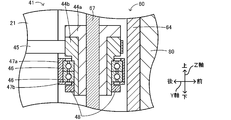
- FIG. 4 is a partial vertical cross-sectional view of a second tool lifting mechanism 41.
- FIG. 2 is a block diagram illustrating an electrical connection relationship in the work execution device 100.
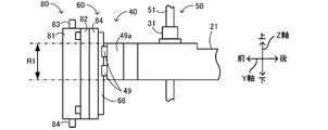
- FIG. 4 is a side view of the vicinity of the distal end side of the first arm 21.
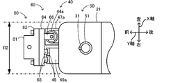
- FIG. 4 is a top view of the vicinity of the distal end side of the first arm 21.
- Explanatory drawing of the screw fastening tool 180 which is the 2nd tool of a modification.
- FIG. 1 is a schematic explanatory diagram of the work execution device 100.
- FIG. 2 is a schematic explanatory diagram of the robot 10.
- FIG. 3 is a perspective view of the second tool lifting / lowering mechanism 41 and the second tool holding unit 60, and shows a state viewed from the upper left rear.
- FIG. 3B shows a state where the second tool holding unit 60 is lowered from the state of FIG. 3A.
- FIG. 4 is a partial vertical sectional view of the second tool lifting mechanism 41.
- FIG. 7 is a top view of the vicinity of the distal end of the first arm 21.
- the left-right direction (X-axis), front-rear direction (Y-axis), and up-down direction (Z-axis) of the task execution device 100 are as shown in FIG. Further, since the robot 10 is movable in the horizontal direction, there is no specific direction fixed in directions other than the up-down direction, but for convenience of explanation, the left-right direction (X-axis) and the front-rear direction (X-axis) shown in FIG. This will be described using (Y axis). The front, rear, left and right directions are parallel to the horizontal direction.
- the work execution device 100 is configured as a device that performs a predetermined work on a work (here, the component P and the board S) to be worked.
- the work execution device 100 includes a robot 10, a pedestal 101, a substrate transfer device 103, a pallet 105, a pressure supply source 106 (see FIG. 5), a control unit 90 for controlling the entire device (see FIG. 5), It has.
- the robot 10 can attach a plurality of tools (also referred to as end effectors), and in the present embodiment, can attach two tools (first and second tools).
- the robot 10 may be capable of mounting a plurality of types of tools as the first and second tools, respectively.
- the pedestal 101 arranges and fixes the robot 10 and the substrate transfer device 103.
- the substrate transport device 103 is configured as a belt conveyor.
- the substrate transport device 103 transports the substrate S to the right, and loads and unloads the substrate S.
- the pressure supply source 106 supplies pressure to the suction nozzle 70 and the dispenser 80 attached to the robot 10.
- the robot 10 is configured as a horizontal articulated robot that performs a predetermined operation on a workpiece.
- the work is not particularly limited, and includes, for example, various components such as a mechanical component, an electrical component, an electronic component, and a chemical component, as well as food, bio, and biological related articles.
- the robot 10 performs a process of collecting and moving a plurality of components P configured as chip-shaped electronic components and the like from a plurality of recesses on the pallet 105, placing the components P on the substrate S, and bonding them. Do.
- the robot 10 includes an arm unit 20, a third support unit 23, a base 24, first and second arm driving units 25 a and 25 b, a first tool elevating unit 30, It includes a one-tool rotating unit 35, a second tool lifting / lowering unit 40, a first tool holding unit 50, and a second tool holding unit 60.
- the arm unit 20 has a plurality of arms connected so as to rotate horizontally with respect to each other.
- the arm unit 20 has first and second arms 21 and 22.
- the arm unit 20 is mounted above the base 24 via the second arm rotation mechanism 26b and the third support unit 23.
- the first and second arms 21 and 22 are attached to the second arm 22 and the first arm 21 in this order from the base 24 side. That is, the first arm 21 is located on the distal end side opposite to the base 24 side among the plurality of arms of the arm section 20.
- the first arm 21 is also referred to as a distal arm.
- the first arm drive unit 25a includes a first arm rotation mechanism 26a, a first arm motor 27a, and an encoder 28a (see FIG. 5).
- the first arm rotation mechanism 26a includes a rotation shaft and a gear mechanism, and has one end (a base end side, here a rear end side) in the longitudinal direction (here, the front-rear direction) of the first arm 21;
- the second arm 22 is connected to one end side (front end side, here front end side) in the longitudinal direction (here, front-rear direction).
- the first arm motor 27a is disposed in the second arm 22.
- the first arm motor 27a rotates the first arm rotation mechanism 26a.
- the first arm rotation mechanism 26a horizontally rotates the first arm 21 about the rotation axis A1 with respect to the second arm 22.
- the encoder 28a detects the rotational position of the first arm motor 27a.
- the second arm driving section 25b includes a second arm rotating mechanism 26b, a second arm motor 27b, and an encoder 28b (see FIG. 5).
- the second arm rotation mechanism 26b includes a rotation shaft and a gear mechanism, and the other end (base end side, here rear end side) of the second arm 22 in the longitudinal direction (here, the front-rear direction). And the third support portion 23 and the base 24.
- the second arm motor 27b is provided in the base 24.
- the second arm motor 27b rotates the second arm rotation mechanism 26b. Accordingly, the second arm rotation mechanism 26b horizontally rotates the second arm 22 about the rotation axis A2 with respect to the base 24.
- the encoder 28b detects the rotational position of the second arm motor 27b.
- the first tool lifting / lowering unit 30 raises / lowers the first tool holding unit 50 to raise / lower the first tool (here, the suction nozzle 70) attached to the first tool holding unit 50.
- the first tool lifting / lowering unit 30 is disposed on the first arm 21.
- the first tool lifting unit 30 includes a first tool lifting mechanism 31, a first tool lifting motor 32, and an encoder 33.
- the first tool lifting / lowering mechanism 31 includes a ball screw nut and the like penetrated by the support shaft 51 of the first tool holding unit 50.
- the first tool lifting / lowering motor 32 rotates the ball screw nut of the first tool lifting / lowering mechanism 31.
- the first tool lifting mechanism 31 moves (elevates) the support shaft 51 configured as the screw shaft of the ball screw in the vertical direction.
- the first tool holder 50 moves up and down with respect to the first arm 21.
- the encoder 33 detects the rotation position of the first tool lifting / lowering motor 32.
- the first tool rotating unit 35 rotates the first tool (here, the suction nozzle 70) attached to the first tool holding unit 50 by rotating (here, rotating) the first tool holding unit 50.
- the first tool rotating unit 35 is disposed in the first arm 21.
- the first tool rotation unit 35 includes a first tool rotation mechanism 36, a first tool rotation motor 37, and an encoder 38.
- the first tool rotation mechanism 36 includes a ball spline nut and the like penetrated by the support shaft 51 of the first tool holding unit 50.
- the first tool rotation motor 37 rotates the ball spline nut of the first tool rotation mechanism 36.
- the first tool rotation mechanism 36 rotates the support shaft 51 configured as the rotation axis of the ball spline.
- the encoder 38 detects a rotation position of the first tool rotation motor 37.
- the first tool holder 50 is provided on the first arm 21.
- the first tool holding unit 50 is configured to attach a first tool for performing an operation on a workpiece below (here, directly below) the first arm 21.
- the first tool holding part 50 includes a support shaft 51, a connection nozzle 52, a first tool mounting member 54, a connection nozzle 57, and a plurality of fixing bolts 59.
- the axial direction of the support shaft 51 is parallel to the up-down direction, and vertically penetrates the other end of the first arm 21 in the longitudinal direction (the front end, here the front end).
- the support shaft 51 vertically penetrates the first tool elevating mechanism 31 and the first tool rotating mechanism 36 as described above, and is moved up and down and rotated by these mechanisms.
- the connection nozzle 52 is provided near the upper end of the support shaft 51, and is connected to the pressure supply source 106 via a pipe (not shown). The pressure from the pressure supply source 106 is supplied to a pressure supply path formed in the support shaft 51 along the axial direction via the connection nozzle 52.
- the first tool mounting member 54 is a member to which the first tool can be mounted. The first tool mounting member 54 is connected to a lower end of the support shaft 51.
- the first tool mounting member 54 has a main body 55 and a flange 56.
- the main body 55 is a columnar member, and a connection nozzle 57 is attached to the outer peripheral surface.
- the flange portion 56 is provided at a lower end of the main body portion 55.
- the lower surface of the flange portion 56 is a mounting surface 56a to which the first tool can be mounted.
- the connection nozzle 57 communicates with a pressure supply path formed in the support shaft 51 and the main body 55.
- the pressure from the pressure supply source 106 passes through the connection nozzle 52, the support shaft 51, the main body 55, and the connection nozzle 57 in this order, and flows through the piping (not shown) connected to the connection nozzle 57 to the suction nozzle 70. It is supplied to the connection nozzle 73.
- the fixing bolt 59 is a member for connecting and fixing the first tool mounting member 54 and the first tool. In the present embodiment, the plurality of fixing bolts 59 are four (only two are shown). The fixing bolt 59 is inserted into the fixing tap 72b of the suction nozzle 70 through a bolt hole formed in the flange portion 56. Thus, the suction nozzle 70 is mounted directly below the mounting surface 56a of the first tool mounting member 54.
- the suction nozzle 70 is an example of a first tool, and is a type of a holding tool for holding a workpiece (here, the component P).
- the suction nozzle 70 suctions and holds the work by using the negative pressure.
- the suction nozzle 70 includes a main body 71, a flange 72, and a connection nozzle 73.
- the main body 71 is a columnar member, and a connection nozzle 73 is attached to the outer peripheral surface.
- the lower end of the main body 71 is open, and this opening communicates with the connection nozzle 73 via a pressure supply passage formed in the main body 71.
- the flange 72 is provided at the upper end of the main body 71.
- the upper surface of the flange portion 72 is a mounting surface 72a.
- the mounting surface 72a contacts the mounting surface 56a when the suction nozzle 70 is mounted on the first tool mounting member 54.
- a plurality of fixing taps 72b (here, four places) are formed in the flange portion 72.
- the second tool lifting / lowering unit 40 raises / lowers the second tool holding unit 60 to raise / lower the second tool (here, the dispenser 80) attached to the second tool holding unit 60.
- the second tool lifting / lowering unit 40 is provided on the first arm 21.
- the second tool lifting / lowering unit 40 includes a second tool lifting / lowering mechanism 41, a second tool lifting / lowering motor 42, and an encoder 43 (see FIG. 5).
- the second tool lifting mechanism 41 includes a ball screw nut 44a, a pulley 44b, a timing belt 45, a plurality of (two in this case) bearings 46, a bearing cover 47a, and a cover.
- a bottom plate 47b, an inner ring support member 48, a slider 49, and a slider support 49a are provided.
- the ball screw nut 44 a is vertically penetrated by the support shaft 67 of the second tool holding part 60. As the ball screw nut 44a rotates, the support shaft 67 moves up and down, and the second tool holder 60 and the dispenser 80 move up and down.
- the pulley 44b is vertically penetrated by the ball screw nut 44a and the support shaft 67.
- the pulley 44b is configured to rotate integrally with the ball screw nut 44a.
- the pulley 44b also serves to support the ball screw nut 44a.
- the timing belt 45 is provided so as to bridge the second tool lifting / lowering motor 42 in the first arm 21 and the pulley 44b outside the first arm 21. The rotation driving force output from the second tool lifting / lowering motor 42 is transmitted to the pulley 44b via the timing belt 45.
- the bearing 46 is a member for rotatably supporting the ball screw nut 44a and the pulley 44b.
- the bearing 46 is configured as, for example, a ball bearing.
- the inner ring of the bearing 46 is vertically penetrated by the ball screw nut 44a, the pulley 44b, and the support shaft 67, and rotates integrally therewith.
- the bearing cover 47a is attached to the front end face of the first arm 21, and protrudes forward from this front end face.
- the bearing cover 47a covers the upper and outer peripheral surfaces of the outer ring of the bearing 46.
- the cover bottom plate 47b is a member configured as a bottom of the bearing cover 47a, and is attached to the bearing cover 47a.
- the cover bottom plate 47b is in contact with the lower surface of the outer ring of the bearing 46.
- the outer ring of the bearing 46 is supported by the bearing cover 47a and the cover bottom plate 47b.
- the inner ring support member 48 is a ring-shaped member attached near the lower end of the pulley 44b.
- the inner ring support member 48 and the pulley 44b are integrally fixed to the inner ring of the bearing 46 by sandwiching the inner ring of the bearing 46 from above and below.
- the slider 49 is configured to be able to move up and down the guide rail 68 of the second tool holding section 60.
- Two sliders 49 are attached to the front end face of the slider supporting portion 49a side by side, and each is disposed so as to extend in the vertical direction.
- the slider support 49a is attached to the front end face of the first arm 21, and protrudes forward from this front end face.
- the slider 49 is attached to the first arm 21 via the slider support 49a.
- the second tool lifting / lowering motor 42 rotates the timing belt 45 of the second tool lifting / lowering mechanism 41 to rotate the ball screw nut 44a and the pulley 44b.
- the support shaft 67 moves up and down as described above, and the second tool holder 60 and the dispenser 80 move up and down (see FIGS. 3A and 3B).
- the second tool lifting / lowering motor 42 and the second tool lifting / lowering mechanism 41 can also raise the second tool holding unit 60 and the dispenser 80 from the state shown in FIG. 3A.
- the encoder 43 detects the rotation position of the second tool lifting / lowering motor 42.
- the second tool holding portion 60 is disposed on the side of the first arm 21, and is disposed in front of the front end face of the first arm 21 in the present embodiment.
- the second tool holding section 60 is attached to the first arm 21 via the second tool lifting / lowering mechanism 41.
- the second tool holding portion 60 is located on the side of the other end face (here, the front end face) in the longitudinal direction of the first arm 21 and at a position along the longitudinal direction of the first arm 21 (here, the first end face) with respect to the front end face.
- the second tool is attached to the front of one arm 21).
- the second tool holding portion 60 includes a second tool mounting member 64, a fixing bolt 64c, a pair of projecting members 66, 66, a support shaft 67, and a guide rail 68.
- the second tool mounting member 64 is a plate-shaped member, and is arranged on the side of the first arm 21.
- the front surface of the second tool mounting member 64 is a mounting surface 64a on which the second tool can be mounted.
- the second tool mounting member 64 has a plurality (four in this case) of fixing taps 64b and one or more (two in this case) positioning pins 64d.
- the fixing tap 64b is open on the mounting surface 64a.
- the positioning pin 64d is a member used for positioning when the second tool is mounted, and protrudes forward from the mounting surface 64a.
- the fixing bolt 64c is inserted into the fixing tap 64b through a bolt hole formed in the dispenser 80. As a result, the dispenser 80 is attached in front of the attachment surface 64a of the second tool attachment member 64.
- the protruding members 66, 66 are disposed near the upper and lower ends of the second tool mounting member 64, and protrude rearward from the second tool mounting member 64.
- a support shaft 67 is mounted between the pair of projecting members 66,66. The axial direction of the support shaft 67 is parallel to the vertical direction, and vertically penetrates the ball screw nut 44a and the like of the second tool lifting mechanism 41 as described above.
- the support shaft 67 is configured as a screw shaft of a ball screw, and moves up and down by rotation of the ball screw nut 44a.
- Two guide rails 68 are provided on the rear surface of the second tool mounting member 64 side by side.
- the guide rail 68 has a longitudinal direction parallel to the vertical direction.
- the dispenser 80 is an example of a second tool, and is a type of a discharge tool that discharges a viscous fluid to a workpiece (here, the component P and the substrate S). As described above, the dispenser 80 performs an operation different from that of the suction nozzle 70.
- the viscous fluid discharged from the dispenser 80 includes, for example, an adhesive, solder, brazing material, and the like. In the present embodiment, the viscous fluid is an adhesive.
- the dispenser 80 discharges the adhesive using positive pressure. As shown in FIG. 2, the dispenser 80 includes a main body 81, an accommodation chamber 81a, a plate-like portion 82, a connection nozzle 83, and a discharge nozzle 84. Since the dispenser 80 has the storage chamber 81a, the vertical length of the tool is longer (the height is higher) than the suction nozzle 70.
- the main body 81 is a substantially rectangular parallelepiped member whose longitudinal direction is parallel to the vertical direction, and has a housing chamber 81a formed therein.
- the storage chamber 81a stores an adhesive.
- the plate-like portion 82 is a plate-like member that is provided at the rear end of the main body 81 and has a portion that protrudes left and right from the main body 81.
- the rear surface of the plate portion 82 is a mounting surface 82a.
- the mounting surface 82a contacts the mounting surface 64a when the dispenser 80 is mounted on the second tool mounting member 64.
- a plurality of (four in this case) bolt holes are formed in the plate-shaped portion 82, and the fixing bolt 64 c is inserted into the bolt holes, and the second tool mounting member 64 and the dispenser 80 are connected and fixed.
- One or more (here, two) positioning holes 82b are formed in the plate portion 82. When the dispenser 80 is mounted on the second tool mounting member 64, the positioning pins 64d are inserted into the positioning holes 82b.
- connection nozzle 83 is provided at the upper end of the main body 81, and is connected to the pressure supply source 106 via a pipe (not shown).
- the discharge nozzle 84 is provided at the lower end of the main body 81 and has a discharge opening that opens downward.
- the connection nozzle 83, the accommodation chamber 81a, and the discharge nozzle 84 communicate with each other in this order via a pressure supply path formed inside the main body 81.
- the second tool holding unit 60 is configured to attach the dispenser 80 to the side of the first arm 21.
- “Attaching to the side of the first arm 21” means that the first arm 21 is attached to a position at least partially overlapping a vertical range where the first arm 21 exists.
- FIG. 6 illustrates a vertical range in which the first arm 21 exists as a region R1.
- the dispenser 80 is attached at a position at least partially overlapping the region R1.
- the dispenser 80 is moved up and down by the second tool elevating unit 40.
- the dispenser 80 at any position where the dispenser 80 can be moved up and down, at least a part of the dispenser 80 is moved to the side of the first arm 21. It is sufficient if they are located (if they overlap with the region R1).
- the mounting surface 64a of the second tool mounting member 64 is directed to the side and outward (in particular, forward) with respect to the first arm 21, the dispenser 80 is moved to the side of the first arm 21. It can be attached to.
- the second tool holding portion 60 including the second tool mounting member 64 is also provided on the side of the first arm 21. That is, the second tool holding unit 60 is attached at a position where at least a part thereof overlaps the region R1.
- the second tool holding unit 60 is configured to mount the dispenser 80 particularly on the front side of the first arm 21.
- “Front of the first arm 21” means the region R2 shown in FIG.
- the region R2 is a region in the left-right direction (the direction perpendicular to the longitudinal direction and the vertical direction of the first arm 21) where the first arm 21 exists, in the region ahead of the front surface of the first arm 21.
- “The dispenser 80 is attached in front of the first arm 21” means that at least a part of the dispenser 80 is attached so as to overlap with the region R2. In the present embodiment, as shown in FIG. 7, the dispenser 80 is attached to the second tool holder 60 so as to be included in the region R2.
- the dispenser 80 has no portion protruding to the left and right of the first arm 21 and the entire area overlaps with the region R2.
- the second tool mounting member 64 or the second tool holding portion 60 including the second tool mounting member 64 may also be provided so as to at least partially overlap this region R2. In the present embodiment, as shown in FIG. 7, the entire second tool holding portion 60 is included in this region R2.
- the control unit 90 is configured as a microprocessor centered on a CPU, and controls the entire work execution device 100.
- the control unit 90 outputs a drive signal to each motor while inputting a signal from each encoder, and controls the operation and position of each mechanism 26a, 26b, 31, 36, 41.
- the control unit 90 outputs a control signal to the substrate transfer device 103 to transfer the substrate S.
- the control unit 90 outputs a control signal to the pressure supply source 106 to control the pressure (positive pressure, negative pressure, or normal pressure) supplied to each of the suction nozzle 70 and the dispenser 80, whereby the suction nozzle 70 and the dispenser 80 are controlled. 80 is controlled.
- the control unit 90 also stores position information of each of the plurality of recesses of the pallet 105, component information such as the type and size of the components P arranged in the recesses, and where and in what order on the substrate S It stores work information including work order information such as whether or not to arrange.
- the transfer and bonding process includes a first process in which the control unit 90 controls the arm unit 20 and one of the suction nozzle 70 and the dispenser 80 to perform an operation on the workpiece using one of the tools. A second process in which the unit 90 controls the arm unit 20 and the other tool to perform an operation using the other tool on the workpiece after performing the first process.
- the pallet 105 on which the plurality of components P are arranged has been previously arranged at a predetermined position on the pedestal 101 by, for example, a pallet supply unit (not shown) or an operator.
- the suction nozzle 70 and the dispenser 80 are attached to the first and second tool holders 50 and 60.
- the control unit 90 first controls the substrate transfer device 103 to transfer the substrate S to a predetermined position near the robot 10. Next, the control unit 90 performs an adhesive application process of applying an adhesive to a predetermined position on the substrate S (a position where the component P is to be bonded next) based on the stored work information. In the adhesive application process, the control unit 90 first horizontally rotates the first and second arms 21 and 22 of the robot 10 by a required amount, and moves the discharge nozzle 84 of the dispenser 80 to a position immediately above a predetermined position on the substrate S. Move. Next, the control unit 90 lowers the dispenser 80 to make the discharge nozzle 84 approach the substrate S.
- control unit 90 applies a positive pressure to the dispenser 80 to discharge the adhesive from the discharge nozzle 84 and apply the adhesive to a predetermined position.
- the control unit 90 may horizontally rotate the arm unit 20 during the discharge of the adhesive so that the adhesive is applied to a predetermined area.
- control unit 90 applies a negative pressure to the dispenser 80 to end the discharge of the adhesive from the discharge nozzle 84, raises the dispenser 80, and ends the adhesive application processing.
- the control unit 90 moves the component P placed on the pallet 105 to a position where the adhesive has been applied in the immediately preceding adhesive application process and places it. Perform processing.
- the control unit 90 sets one of the components P arranged in each of the plurality of concave portions of the pallet 105 as a processing target.
- the control unit 90 horizontally rotates the first and second arms 21 and 22 by a required amount, and moves the suction nozzle 70 right above the component P to be processed.
- the control unit 90 lowers the suction nozzle 70, applies a negative pressure to the suction nozzle 70, and causes the suction nozzle 70 to collect the component P.
- the control unit 90 raises the suction nozzle 70, horizontally rotates the first and second arms 21 and 22 by a required amount to move the component P to a position immediately above the position where the adhesive is applied, and moves the suction nozzle 70.
- the component P is lowered to place the component P on the substrate S.
- the control unit 90 may adjust the direction of the component P using the first tool rotation unit 35 as necessary.
- the control unit 90 applies a positive pressure (or normal pressure) to the suction nozzle 70 to release the holding of the component P by the suction nozzle 70, raises the suction nozzle 70, and ends the transfer processing.
- the control unit 90 alternately repeats the above-described adhesive application processing and transfer processing based on the stored work information, and performs processing for all components P to be transferred and bonded onto the substrate S. Is completed, the transfer bonding process ends.
- the control unit 90 controls the arm unit 20 and the dispenser 80 to apply the adhesive to the substrate S (an example of the first process), and the adhesive is applied by the adhesive application process.
- a transfer process (an example of a second process) for mounting the component P on the substrate S that has been performed using the suction nozzle 70 is performed.
- the control unit 90 applies an adhesive to the component P placed in the transfer processing by the adhesive application processing, and performs the next transfer processing.
- the transfer processing may be regarded as an example of the first processing
- the adhesive application processing of applying an adhesive on the component P placed in the transfer processing may be regarded as an example of the second processing.
- the first tool here, the suction nozzle 70
- the second tool the dispenser 80 in this case
- the suction nozzle 70 which is the lower tool
- the suction nozzle 70 is attached to the first tool holding unit 50 as a first tool, and the higher tool is used.
- the robot 10 of the present embodiment is suitable for mounting two tools having different heights.
- the first arm 21 has a longitudinal direction, and horizontally rotates around a rotation axis A1 provided at one end side (here, the rear end side) in the longitudinal direction.
- the second tool holding portion 60 is located on the side of the other end surface (here, the front end surface) in the longitudinal direction of the first arm 21 and at a position along the longitudinal direction of the first arm 21 with respect to the other end surface. (In the front). Accordingly, the dispenser 80 can be moved to a position away from the base 24 by the arm unit 20, and the movable range of the dispenser 80 in the horizontal direction is widened.
- the robot 10 includes a first tool lifting mechanism 31 that raises and lowers the first tool holder 50 with respect to the first arm 21, and a second tool lifter that raises and lowers the second tool holder 60 with respect to the first arm 21. And a mechanism 41. Therefore, the suction nozzle 70 and the dispenser 80 can be moved up and down by the first and second elevating mechanisms 31 and 41, thereby facilitating work on the work.
- the robot 10 includes the suction nozzle 70 attached to the first tool holding unit 50.
- the robot 10 includes a dispenser 80 that is attached to the second tool holding unit 60 and that is higher in the vertical direction than the suction nozzle 70 and performs a task different from that of the suction nozzle 70.
- two tools that perform different tasks often have different heights.
- the dispenser 80 which is higher than the suction nozzle 70, is attached to the second tool holding unit 60, so that when the arm unit 20 is moved, the dispenser 80 moves to another object below the first arm 21. Inconveniences such as contact with the hard disk are less likely to occur.
- the first tool is a holding tool (here, the suction nozzle 70) for holding the work (here, the component P).
- the second tool is a discharge tool (here, a dispenser 80) having a storage chamber 81a that stores a viscous fluid and a discharge nozzle 84 that discharges the viscous fluid.
- the height of the dispenser 80 tends to be higher than that of the suction nozzle 70 by the amount of the storage chamber 81a.
- the robot 10 is suitable for attaching the suction nozzle 70 and the dispenser 80.
- the work execution device 100 further includes the robot 10 including the suction nozzle 70 and the dispenser 80 that perform different works.
- the work execution device 100 controls the arm unit 20, the suction nozzle 70, and one of the tools of the dispenser 80 to perform the work using the one tool on the work (here, the component P or the substrate S).
- a control unit 90 is provided for performing a first process and a second process of controlling the arm unit 20 and the other tool to perform an operation using the other tool on the workpiece after the first process. ing.
- the work execution device 100 can perform work efficiently using the suction nozzle 70 and the dispenser 80 that perform different works.
- the suction nozzle 70 is illustrated as the first tool, but the first tool is not limited to the suction nozzle 70 and may be a holding tool for holding a work.
- the holding tool other than the suction nozzle 70 include a mechanical chuck that grips the work using pressure, a tool that attracts and holds the work by magnetic force, and the like.
- a tool other than the holding tool may be attached to the first tool holding unit 50 as the first tool.
- the dispenser 80 is exemplified as the second tool, but the present invention is not limited to this.
- the screw tightening tool 180 shown in FIG. 8 may be used as the second tool.
- the same components of the screw tightening tool 180 as those of the dispenser 80 are denoted by the same reference numerals in FIG. 8, and detailed description thereof will be omitted.
- the screw tightening tool 180 is a tool for rotating an external screw to tighten a screw.
- the screw tightening tool 180 includes a motor 181a provided in the main body 81 and a driver 184 attached to a lower end of the main body 81. A plurality of types of the drivers 184 may be exchangeably attached to the main body 81.
- the motor 181a receives a control signal from the control unit 90 via electric wiring (not shown) and rotates the driver 184 around the shaft.
- the robot 10 may include a suction nozzle 70 attached to the first tool holder 50 and a screw tightening tool 180 attached to the second tool holder 60.
- the control unit 90 may hold the male screw as the work by the suction nozzle 70 and move the male screw to a predetermined position, and then use the screw tightening tool 180 to tighten the male screw. Since the screw tightening tool 180 includes the motor 181a, the height in the vertical direction is more likely to be higher than the suction nozzle 70.
- the robot 10 of the above-described embodiment is suitable for attaching the suction nozzle 70 and the screw tightening tool 180.
- the dispenser 80 as the second tool is a tool that performs an operation different from that of the suction nozzle 70 as the first tool, but is not limited thereto.
- the first tool and the second tool may be tools that perform the same operation. Even when two tools performing the same operation are mounted, if one of the two tools has a higher height in the vertical direction than the other, the higher tool is used as the second tool as the second tool holding portion 60. It should be attached to.
- the second tool holding unit 60 is configured to attach the second tool to the front of the first arm 21.
- the second tool is attached not only to the front of the first arm 21 but to the side. What is necessary is just to be comprised as follows.
- the second tool holding unit 60 may be configured to attach the second tool to the left or right of the first arm 21.
- the robot 10 may include a camera that captures an image of the lower side, separately from the first and second tools.
- the tools attached to the first and second tools may be tools other than the camera.
- the second tool may have a higher height in use than the first tool.
- the “height during use” refers to at least one of a vertical distance from the workpiece at the time of use and a vertical position at the time of use with respect to an arm (eg, the first arm 21) to which the tool is attached.
- the imaging tool 280 shown in FIG. 9 may be used as the second tool.
- the imaging tool 280 is a tool that captures an image of a work.
- the imaging tool 280 includes an imaging unit 281 and a plate portion 282.
- the imaging unit 281 includes an optical system such as a lens and an imaging device such as a CCD.
- the imaging range of the imaging unit 281 is below the imaging unit 281.
- the plate portion 282 is a flat plate-like member, and is configured to be attachable to the second tool attachment member 64 in the same manner as the plate portion 82.
- An imaging unit 281 is mounted in front of the plate-like portion 282.
- a work for example, a component P
- a lower work for example, the component P or the substrate S
- the second tool lifting mechanism 41 raises and lowers the imaging tool 280, so that it is possible to adjust the distance between the imaging unit 281 and the object during imaging to perform focusing.
- the control unit 90 derives a contrast based on luminance information of image data generated by the imaging unit 281 and controls the second tool lifting / lowering mechanism 41 based on an evaluation value derived based on the contrast, Focusing may be performed.
- the imaging tool 280 especially the imaging unit 281 performs an operation (imaging) vertically away from the work as compared with the suction nozzle 70, the height in use is higher than the suction nozzle 70.
- the imaging unit 281 may be too close to the workpiece and the height during use may be inappropriate.
- the imaging unit 281 may not be able to focus on the work, or the work may not be included in the field of view of the imaging unit 281.
- the second tool here, the imaging tool 280
- the robot 10 is also suitable for mounting two tools having different heights when used.
- an imaging unit 285, which is a tool different from the suction nozzle 70 and the imaging tool 280, is fixedly provided on the right side of the first arm 21.
- the imaging unit 285 may be omitted.
- the horizontal articulated robot and the work execution device of the present disclosure may be configured as follows.
- the distal end side arm has a longitudinal direction, horizontally turns around a rotation axis provided at one end side in the longitudinal direction
- the second tool holding unit includes the distal end.
- the second tool may be configured to be mounted on a side of the other end surface in the longitudinal direction of the side arm and along the longitudinal direction with respect to the other end surface. With this configuration, the second tool can be moved to a position away from the base by the arm, and the movable range of the second tool in the horizontal direction is widened.
- a horizontal articulated robot includes a first tool lifting mechanism that raises and lowers the first tool holding unit with respect to the distal arm, and a second tool that raises and lowers the second tool holding unit with respect to the distal arm. And a tool elevating mechanism.
- at least one of the first and second tools can be moved up and down by the elevating mechanism, thereby making it easier to work on the workpiece.
- the horizontal articulated robot includes the first tool attached to the first tool holding unit, and the first tool attached to the second tool holding unit, the height of which is higher in the vertical direction than the first tool. And the second tool that performs an operation different from that of the first tool.
- two tools that perform different tasks often have different heights.
- the second tool which is higher than the first tool, is attached to the second tool holding portion. Inconveniences such as contact with other objects are less likely to occur.
- the first tool is a holding tool for holding the work
- the second tool contains a viscous fluid. It may be a discharge tool having a storage chamber and a discharge nozzle for discharging the viscous fluid.
- the height of the ejection tool tends to be higher than that of the holding tool by the amount of the storage chamber.
- This horizontal articulated robot is suitable for mounting such a holding tool and a discharging tool.
- the first tool is a holding tool that holds a male screw as the work
- the second tool is a male screw. It may be a screw tightening tool that rotates the screw to tighten the screw.
- the screw tightening tool tends to be higher than the holding tool.
- This horizontal articulated robot is suitable for mounting such a holding tool and a screw tightening tool.
- the second tool is provided with at least the second tool lifting mechanism, attached to the second tool holding unit, and capturing an image. And the first tool attached to the first tool holding part and performing a different operation from the second tool.
- a tool for capturing an image an imaging tool
- This horizontal articulated robot is suitable for mounting such an imaging tool and a tool for performing work other than imaging.
- the second tool imaging tool
- the second tool elevating mechanism so that the distance to the target can be adjusted at the time of imaging to perform focusing.
- the work execution device includes: A horizontal articulated robot having first and second tools for performing different tasks, A first process of controlling the arm unit and one of the first and second tools to perform an operation on the workpiece using the one tool; and A control unit that performs a second process of performing an operation using the other tool on the workpiece after controlling the other tool of the two tools and performing the first process; It is provided with.
- This work execution device has the same effect as the above-described horizontal articulated robot of the present disclosure, for example, an effect that it is suitable for mounting two tools having at least one of a height of a tool and a height when the tool is used different from each other. can get.
- the work can be efficiently performed using the first and second tools that perform different work.
- a task execution device includes the horizontal articulated robot according to any one of the above-described embodiments. Therefore, this work execution device is suitable for mounting two tools having at least one of different effects from the horizontal articulated robot of the present disclosure, for example, at least one of the height of the tool and the height when the tool is used. The effect is obtained.
- the present invention is applicable to various industries that work on workpieces such as components and boards.
Landscapes
- Engineering & Computer Science (AREA)
- Robotics (AREA)
- Mechanical Engineering (AREA)
- Manipulator (AREA)
Abstract
L'invention concerne un robot articulé horizontal qui est pourvu : d'une base ; d'une section de bras qui est fixée à la base et qui comprend une pluralité de bras reliés de façon à pouvoir tourner horizontalement les uns par rapport aux autres ; d'une première section de maintien d'outil qui est agencée sur un bras côté pointe positionné sur un côté pointe opposé au côté base parmi la pluralité de bras et qui sert à fixer, sous le bras côté pointe, un premier outil pour effectuer un travail sur une pièce à travailler ; et une seconde section de maintien d'outil qui est agencée sur le bras côté pointe et qui sert à fixer un second outil pour effectuer un travail sur une pièce à travailler sur le côté du bras côté pointe.
Priority Applications (3)
| Application Number | Priority Date | Filing Date | Title |
|---|---|---|---|
| JP2020528634A JP7033204B2 (ja) | 2018-07-05 | 2018-07-05 | 水平多関節ロボット及び作業実行装置 |
| CN201880095271.6A CN112368114B (zh) | 2018-07-05 | 2018-07-05 | 水平多关节机器人以及作业执行装置 |
| PCT/JP2018/025569 WO2020008601A1 (fr) | 2018-07-05 | 2018-07-05 | Robot articulé horizontal et dispositif d'exécution d'opération |
Applications Claiming Priority (1)
| Application Number | Priority Date | Filing Date | Title |
|---|---|---|---|
| PCT/JP2018/025569 WO2020008601A1 (fr) | 2018-07-05 | 2018-07-05 | Robot articulé horizontal et dispositif d'exécution d'opération |
Publications (1)
| Publication Number | Publication Date |
|---|---|
| WO2020008601A1 true WO2020008601A1 (fr) | 2020-01-09 |
Family
ID=69059406
Family Applications (1)
| Application Number | Title | Priority Date | Filing Date |
|---|---|---|---|
| PCT/JP2018/025569 Ceased WO2020008601A1 (fr) | 2018-07-05 | 2018-07-05 | Robot articulé horizontal et dispositif d'exécution d'opération |
Country Status (3)
| Country | Link |
|---|---|
| JP (1) | JP7033204B2 (fr) |
| CN (1) | CN112368114B (fr) |
| WO (1) | WO2020008601A1 (fr) |
Cited By (1)
| Publication number | Priority date | Publication date | Assignee | Title |
|---|---|---|---|---|
| WO2024180630A1 (fr) * | 2023-02-27 | 2024-09-06 | 株式会社Fuji | Dispositif de travail et unité de maintien |
Families Citing this family (2)
| Publication number | Priority date | Publication date | Assignee | Title |
|---|---|---|---|---|
| JP2024017305A (ja) * | 2022-07-27 | 2024-02-08 | 株式会社新川 | 電子部品検出装置、電子部品検出方法及び電子部品検出プログラム |
| CN116436228B (zh) * | 2023-04-24 | 2025-10-10 | 深圳市鑫昌顺精密机械有限公司 | 一种转子铁芯点胶装置 |
Citations (4)
| Publication number | Priority date | Publication date | Assignee | Title |
|---|---|---|---|---|
| JPS6258186U (fr) * | 1985-09-28 | 1987-04-10 | ||
| JPH08108386A (ja) * | 1994-10-05 | 1996-04-30 | Sony Corp | ロボット制御方法 |
| JP2014124765A (ja) * | 2012-12-27 | 2014-07-07 | Nitto Seiko Co Ltd | 自動ねじ締め装置 |
| JP2017222001A (ja) * | 2016-06-15 | 2017-12-21 | セイコーエプソン株式会社 | ロボット、制御装置およびロボットシステム |
Family Cites Families (8)
| Publication number | Priority date | Publication date | Assignee | Title |
|---|---|---|---|---|
| JPS6328583A (ja) * | 1986-07-16 | 1988-02-06 | 三菱電機株式会社 | 多関節ロボツト |
| JPH079460U (ja) * | 1993-07-15 | 1995-02-10 | エヌ・オー・ケー・メグラスティック株式会社 | 塗布機 |
| JPH08125320A (ja) * | 1994-10-24 | 1996-05-17 | Toshiba Corp | 接着剤塗布装置 |
| JP4156421B2 (ja) * | 2003-03-27 | 2008-09-24 | 三洋機工株式会社 | アーム式ロボット |
| JP5272588B2 (ja) * | 2008-09-01 | 2013-08-28 | セイコーエプソン株式会社 | 水平多関節型ロボット |
| JP3175497U (ja) * | 2012-02-24 | 2012-05-17 | 月平 馬 | スカラ型ロボット |
| JP6353252B2 (ja) * | 2014-03-27 | 2018-07-04 | 新明和工業株式会社 | 塗布装置 |
| JP6347640B2 (ja) * | 2014-03-27 | 2018-06-27 | 新明和工業株式会社 | 塗布装置 |
-
2018
- 2018-07-05 WO PCT/JP2018/025569 patent/WO2020008601A1/fr not_active Ceased
- 2018-07-05 JP JP2020528634A patent/JP7033204B2/ja active Active
- 2018-07-05 CN CN201880095271.6A patent/CN112368114B/zh active Active
Patent Citations (4)
| Publication number | Priority date | Publication date | Assignee | Title |
|---|---|---|---|---|
| JPS6258186U (fr) * | 1985-09-28 | 1987-04-10 | ||
| JPH08108386A (ja) * | 1994-10-05 | 1996-04-30 | Sony Corp | ロボット制御方法 |
| JP2014124765A (ja) * | 2012-12-27 | 2014-07-07 | Nitto Seiko Co Ltd | 自動ねじ締め装置 |
| JP2017222001A (ja) * | 2016-06-15 | 2017-12-21 | セイコーエプソン株式会社 | ロボット、制御装置およびロボットシステム |
Cited By (1)
| Publication number | Priority date | Publication date | Assignee | Title |
|---|---|---|---|---|
| WO2024180630A1 (fr) * | 2023-02-27 | 2024-09-06 | 株式会社Fuji | Dispositif de travail et unité de maintien |
Also Published As
| Publication number | Publication date |
|---|---|
| CN112368114B (zh) | 2024-03-01 |
| JPWO2020008601A1 (ja) | 2021-06-24 |
| JP7033204B2 (ja) | 2022-03-09 |
| CN112368114A (zh) | 2021-02-12 |
Similar Documents
| Publication | Publication Date | Title |
|---|---|---|
| CN106956370B (zh) | 加工装置的搬送机构 | |
| JP5226394B2 (ja) | フランジの端面修正方法 | |
| CN108655802B (zh) | 机床系统以及移动方法 | |
| JP7033204B2 (ja) | 水平多関節ロボット及び作業実行装置 | |
| JP2012223839A (ja) | ロボットシステムおよびロボットシステムの駆動方法 | |
| JP6632367B2 (ja) | 組立装置、組立装置の制御方法、および物品の製造方法 | |
| JP6202962B2 (ja) | 切削装置 | |
| JP2019130646A (ja) | 作業ロボットシステム | |
| JP2019209448A (ja) | 加工システム及び加工方法 | |
| JP6218782B2 (ja) | 締結作業方法及び締結システム | |
| CN1729079B (zh) | 机床工件的加工方法及用于该方法的装配架和支承装置 | |
| JPWO2014115244A1 (ja) | ロボットシステム | |
| US10850387B2 (en) | Automatic workpiece transfer machine | |
| JP4700590B2 (ja) | 横形マシンニングセンタ | |
| JP6830731B2 (ja) | 切削装置 | |
| WO2005053015A1 (fr) | Appareil de manipulation | |
| TWI725350B (zh) | 夾具組裝體及焊接裝置 | |
| CN110944809A (zh) | 末端执行器 | |
| CN113102889A (zh) | 一种薄壁钻基体加工系统 | |
| JP6619817B2 (ja) | 作業実行装置 | |
| TWM536998U (zh) | 工件取放裝置 | |
| KR200472836Y1 (ko) | 절삭 유닛 및 그 응용설비 | |
| US20250360585A1 (en) | Jig device and jig unit | |
| CN112218742A (zh) | 垂直多关节机器人及作业装置 | |
| WO2024180630A1 (fr) | Dispositif de travail et unité de maintien |
Legal Events
| Date | Code | Title | Description |
|---|---|---|---|
| 121 | Ep: the epo has been informed by wipo that ep was designated in this application |
Ref document number: 18925378 Country of ref document: EP Kind code of ref document: A1 |
|
| ENP | Entry into the national phase |
Ref document number: 2020528634 Country of ref document: JP Kind code of ref document: A |
|
| NENP | Non-entry into the national phase |
Ref country code: DE |
|
| 122 | Ep: pct application non-entry in european phase |
Ref document number: 18925378 Country of ref document: EP Kind code of ref document: A1 |