WO2020008601A1 - 水平多関節ロボット及び作業実行装置 - Google Patents
水平多関節ロボット及び作業実行装置 Download PDFInfo
- Publication number
- WO2020008601A1 WO2020008601A1 PCT/JP2018/025569 JP2018025569W WO2020008601A1 WO 2020008601 A1 WO2020008601 A1 WO 2020008601A1 JP 2018025569 W JP2018025569 W JP 2018025569W WO 2020008601 A1 WO2020008601 A1 WO 2020008601A1
- Authority
- WO
- WIPO (PCT)
- Prior art keywords
- tool
- arm
- articulated robot
- horizontal articulated
- work
- Prior art date
- Legal status (The legal status is an assumption and is not a legal conclusion. Google has not performed a legal analysis and makes no representation as to the accuracy of the status listed.)
- Ceased
Links
Images





Classifications
-
- B—PERFORMING OPERATIONS; TRANSPORTING
- B25—HAND TOOLS; PORTABLE POWER-DRIVEN TOOLS; MANIPULATORS
- B25J—MANIPULATORS; CHAMBERS PROVIDED WITH MANIPULATION DEVICES
- B25J15/00—Gripping heads and other end effectors
-
- B—PERFORMING OPERATIONS; TRANSPORTING
- B25—HAND TOOLS; PORTABLE POWER-DRIVEN TOOLS; MANIPULATORS
- B25J—MANIPULATORS; CHAMBERS PROVIDED WITH MANIPULATION DEVICES
- B25J9/00—Program-controlled manipulators
- B25J9/06—Program-controlled manipulators characterised by multi-articulated arms
Definitions
- the present disclosure relates to a horizontal articulated robot and a work execution device.
- Patent Document 1 a horizontal articulated robot provided with a plurality of arms that rotate horizontally has been known (for example, Patent Document 1).
- the horizontal articulated robot described in Patent Document 1 includes a first arm rotatably provided on a base, a second arm rotatably provided on the first arm, and a second arm.
- a main shaft provided to penetrate the arm vertically.
- the main shaft is supported rotatably and vertically.
- a tool such as a hand for transporting an object to be transported is attached to a lower end portion of the main shaft.
- the height in the vertical direction during use (at least one of the vertical distance from the workpiece and the vertical position based on the arm to which the tool is attached) differs depending on the tool. Therefore, when a plurality of tools having different heights during use are all attached to the lower end of the main shaft, that is, below the second arm, the height during use of one of the tools may become inappropriate.
- the present disclosure has been made in order to solve the above-described problem, and provides a horizontal articulated robot suitable for mounting two tools having at least one of a height of a tool and a height when the tool is different from each other. Its main purpose is to:
- the present disclosure employs the following means in order to achieve the above-described main object.
- the horizontal articulated robot of the present disclosure A base, An arm unit having a plurality of arms connected to rotate horizontally with respect to each other, and attached to the base; A first tool holding unit, which is disposed on a distal end arm located on a distal end side opposite to the base side of the plurality of arms, and for attaching a first tool for performing work on a work below the distal end arm; Department and A second tool holding unit disposed on the distal arm and for attaching a second tool for performing a work on a workpiece to a side of the distal arm; It is provided with.
- the first tool can be attached below the distal arm by the first tool holder, and the second tool can be attached to the side of the distal arm by the second tool holder.
- the lower one is attached to the first tool holder as the first tool
- the higher tool is attached to the second tool holder as the second tool.
- the portion of the higher tool protruding below the distal arm can be reduced.
- a problem such as that the tool having the higher height (the second tool) comes into contact with another object below the distal arm is less likely to occur.
- this horizontal articulated robot is suitable for mounting two tools having at least one of a tool height and a height at the time of use of the tool different from each other.
- “horizontal” includes substantially horizontal.
- the first tool and the second tool may be tools that work on the same work, or tools that work on different works.
- FIG. 1 is a schematic explanatory diagram of a work execution device 100.
- FIG. 2 is a schematic explanatory diagram of the robot 10.
- FIG. 5 is a perspective view of a second tool lifting mechanism 41 and a second tool holding unit 60.
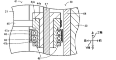
- FIG. 4 is a partial vertical cross-sectional view of a second tool lifting mechanism 41.
- FIG. 2 is a block diagram illustrating an electrical connection relationship in the work execution device 100.
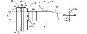
- FIG. 4 is a side view of the vicinity of the distal end side of the first arm 21.
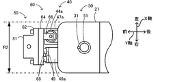
- FIG. 4 is a top view of the vicinity of the distal end side of the first arm 21.
- Explanatory drawing of the screw fastening tool 180 which is the 2nd tool of a modification.
- FIG. 1 is a schematic explanatory diagram of the work execution device 100.
- FIG. 2 is a schematic explanatory diagram of the robot 10.
- FIG. 3 is a perspective view of the second tool lifting / lowering mechanism 41 and the second tool holding unit 60, and shows a state viewed from the upper left rear.
- FIG. 3B shows a state where the second tool holding unit 60 is lowered from the state of FIG. 3A.
- FIG. 4 is a partial vertical sectional view of the second tool lifting mechanism 41.
- FIG. 7 is a top view of the vicinity of the distal end of the first arm 21.
- the left-right direction (X-axis), front-rear direction (Y-axis), and up-down direction (Z-axis) of the task execution device 100 are as shown in FIG. Further, since the robot 10 is movable in the horizontal direction, there is no specific direction fixed in directions other than the up-down direction, but for convenience of explanation, the left-right direction (X-axis) and the front-rear direction (X-axis) shown in FIG. This will be described using (Y axis). The front, rear, left and right directions are parallel to the horizontal direction.
- the work execution device 100 is configured as a device that performs a predetermined work on a work (here, the component P and the board S) to be worked.
- the work execution device 100 includes a robot 10, a pedestal 101, a substrate transfer device 103, a pallet 105, a pressure supply source 106 (see FIG. 5), a control unit 90 for controlling the entire device (see FIG. 5), It has.
- the robot 10 can attach a plurality of tools (also referred to as end effectors), and in the present embodiment, can attach two tools (first and second tools).
- the robot 10 may be capable of mounting a plurality of types of tools as the first and second tools, respectively.
- the pedestal 101 arranges and fixes the robot 10 and the substrate transfer device 103.
- the substrate transport device 103 is configured as a belt conveyor.
- the substrate transport device 103 transports the substrate S to the right, and loads and unloads the substrate S.
- the pressure supply source 106 supplies pressure to the suction nozzle 70 and the dispenser 80 attached to the robot 10.
- the robot 10 is configured as a horizontal articulated robot that performs a predetermined operation on a workpiece.
- the work is not particularly limited, and includes, for example, various components such as a mechanical component, an electrical component, an electronic component, and a chemical component, as well as food, bio, and biological related articles.
- the robot 10 performs a process of collecting and moving a plurality of components P configured as chip-shaped electronic components and the like from a plurality of recesses on the pallet 105, placing the components P on the substrate S, and bonding them. Do.
- the robot 10 includes an arm unit 20, a third support unit 23, a base 24, first and second arm driving units 25 a and 25 b, a first tool elevating unit 30, It includes a one-tool rotating unit 35, a second tool lifting / lowering unit 40, a first tool holding unit 50, and a second tool holding unit 60.
- the arm unit 20 has a plurality of arms connected so as to rotate horizontally with respect to each other.
- the arm unit 20 has first and second arms 21 and 22.
- the arm unit 20 is mounted above the base 24 via the second arm rotation mechanism 26b and the third support unit 23.
- the first and second arms 21 and 22 are attached to the second arm 22 and the first arm 21 in this order from the base 24 side. That is, the first arm 21 is located on the distal end side opposite to the base 24 side among the plurality of arms of the arm section 20.
- the first arm 21 is also referred to as a distal arm.
- the first arm drive unit 25a includes a first arm rotation mechanism 26a, a first arm motor 27a, and an encoder 28a (see FIG. 5).
- the first arm rotation mechanism 26a includes a rotation shaft and a gear mechanism, and has one end (a base end side, here a rear end side) in the longitudinal direction (here, the front-rear direction) of the first arm 21;
- the second arm 22 is connected to one end side (front end side, here front end side) in the longitudinal direction (here, front-rear direction).
- the first arm motor 27a is disposed in the second arm 22.
- the first arm motor 27a rotates the first arm rotation mechanism 26a.
- the first arm rotation mechanism 26a horizontally rotates the first arm 21 about the rotation axis A1 with respect to the second arm 22.
- the encoder 28a detects the rotational position of the first arm motor 27a.
- the second arm driving section 25b includes a second arm rotating mechanism 26b, a second arm motor 27b, and an encoder 28b (see FIG. 5).
- the second arm rotation mechanism 26b includes a rotation shaft and a gear mechanism, and the other end (base end side, here rear end side) of the second arm 22 in the longitudinal direction (here, the front-rear direction). And the third support portion 23 and the base 24.
- the second arm motor 27b is provided in the base 24.
- the second arm motor 27b rotates the second arm rotation mechanism 26b. Accordingly, the second arm rotation mechanism 26b horizontally rotates the second arm 22 about the rotation axis A2 with respect to the base 24.
- the encoder 28b detects the rotational position of the second arm motor 27b.
- the first tool lifting / lowering unit 30 raises / lowers the first tool holding unit 50 to raise / lower the first tool (here, the suction nozzle 70) attached to the first tool holding unit 50.
- the first tool lifting / lowering unit 30 is disposed on the first arm 21.
- the first tool lifting unit 30 includes a first tool lifting mechanism 31, a first tool lifting motor 32, and an encoder 33.
- the first tool lifting / lowering mechanism 31 includes a ball screw nut and the like penetrated by the support shaft 51 of the first tool holding unit 50.
- the first tool lifting / lowering motor 32 rotates the ball screw nut of the first tool lifting / lowering mechanism 31.
- the first tool lifting mechanism 31 moves (elevates) the support shaft 51 configured as the screw shaft of the ball screw in the vertical direction.
- the first tool holder 50 moves up and down with respect to the first arm 21.
- the encoder 33 detects the rotation position of the first tool lifting / lowering motor 32.
- the first tool rotating unit 35 rotates the first tool (here, the suction nozzle 70) attached to the first tool holding unit 50 by rotating (here, rotating) the first tool holding unit 50.
- the first tool rotating unit 35 is disposed in the first arm 21.
- the first tool rotation unit 35 includes a first tool rotation mechanism 36, a first tool rotation motor 37, and an encoder 38.
- the first tool rotation mechanism 36 includes a ball spline nut and the like penetrated by the support shaft 51 of the first tool holding unit 50.
- the first tool rotation motor 37 rotates the ball spline nut of the first tool rotation mechanism 36.
- the first tool rotation mechanism 36 rotates the support shaft 51 configured as the rotation axis of the ball spline.
- the encoder 38 detects a rotation position of the first tool rotation motor 37.
- the first tool holder 50 is provided on the first arm 21.
- the first tool holding unit 50 is configured to attach a first tool for performing an operation on a workpiece below (here, directly below) the first arm 21.
- the first tool holding part 50 includes a support shaft 51, a connection nozzle 52, a first tool mounting member 54, a connection nozzle 57, and a plurality of fixing bolts 59.
- the axial direction of the support shaft 51 is parallel to the up-down direction, and vertically penetrates the other end of the first arm 21 in the longitudinal direction (the front end, here the front end).
- the support shaft 51 vertically penetrates the first tool elevating mechanism 31 and the first tool rotating mechanism 36 as described above, and is moved up and down and rotated by these mechanisms.
- the connection nozzle 52 is provided near the upper end of the support shaft 51, and is connected to the pressure supply source 106 via a pipe (not shown). The pressure from the pressure supply source 106 is supplied to a pressure supply path formed in the support shaft 51 along the axial direction via the connection nozzle 52.
- the first tool mounting member 54 is a member to which the first tool can be mounted. The first tool mounting member 54 is connected to a lower end of the support shaft 51.
- the first tool mounting member 54 has a main body 55 and a flange 56.
- the main body 55 is a columnar member, and a connection nozzle 57 is attached to the outer peripheral surface.
- the flange portion 56 is provided at a lower end of the main body portion 55.
- the lower surface of the flange portion 56 is a mounting surface 56a to which the first tool can be mounted.
- the connection nozzle 57 communicates with a pressure supply path formed in the support shaft 51 and the main body 55.
- the pressure from the pressure supply source 106 passes through the connection nozzle 52, the support shaft 51, the main body 55, and the connection nozzle 57 in this order, and flows through the piping (not shown) connected to the connection nozzle 57 to the suction nozzle 70. It is supplied to the connection nozzle 73.
- the fixing bolt 59 is a member for connecting and fixing the first tool mounting member 54 and the first tool. In the present embodiment, the plurality of fixing bolts 59 are four (only two are shown). The fixing bolt 59 is inserted into the fixing tap 72b of the suction nozzle 70 through a bolt hole formed in the flange portion 56. Thus, the suction nozzle 70 is mounted directly below the mounting surface 56a of the first tool mounting member 54.
- the suction nozzle 70 is an example of a first tool, and is a type of a holding tool for holding a workpiece (here, the component P).
- the suction nozzle 70 suctions and holds the work by using the negative pressure.
- the suction nozzle 70 includes a main body 71, a flange 72, and a connection nozzle 73.
- the main body 71 is a columnar member, and a connection nozzle 73 is attached to the outer peripheral surface.
- the lower end of the main body 71 is open, and this opening communicates with the connection nozzle 73 via a pressure supply passage formed in the main body 71.
- the flange 72 is provided at the upper end of the main body 71.
- the upper surface of the flange portion 72 is a mounting surface 72a.
- the mounting surface 72a contacts the mounting surface 56a when the suction nozzle 70 is mounted on the first tool mounting member 54.
- a plurality of fixing taps 72b (here, four places) are formed in the flange portion 72.
- the second tool lifting / lowering unit 40 raises / lowers the second tool holding unit 60 to raise / lower the second tool (here, the dispenser 80) attached to the second tool holding unit 60.
- the second tool lifting / lowering unit 40 is provided on the first arm 21.
- the second tool lifting / lowering unit 40 includes a second tool lifting / lowering mechanism 41, a second tool lifting / lowering motor 42, and an encoder 43 (see FIG. 5).
- the second tool lifting mechanism 41 includes a ball screw nut 44a, a pulley 44b, a timing belt 45, a plurality of (two in this case) bearings 46, a bearing cover 47a, and a cover.
- a bottom plate 47b, an inner ring support member 48, a slider 49, and a slider support 49a are provided.
- the ball screw nut 44 a is vertically penetrated by the support shaft 67 of the second tool holding part 60. As the ball screw nut 44a rotates, the support shaft 67 moves up and down, and the second tool holder 60 and the dispenser 80 move up and down.
- the pulley 44b is vertically penetrated by the ball screw nut 44a and the support shaft 67.
- the pulley 44b is configured to rotate integrally with the ball screw nut 44a.
- the pulley 44b also serves to support the ball screw nut 44a.
- the timing belt 45 is provided so as to bridge the second tool lifting / lowering motor 42 in the first arm 21 and the pulley 44b outside the first arm 21. The rotation driving force output from the second tool lifting / lowering motor 42 is transmitted to the pulley 44b via the timing belt 45.
- the bearing 46 is a member for rotatably supporting the ball screw nut 44a and the pulley 44b.
- the bearing 46 is configured as, for example, a ball bearing.
- the inner ring of the bearing 46 is vertically penetrated by the ball screw nut 44a, the pulley 44b, and the support shaft 67, and rotates integrally therewith.
- the bearing cover 47a is attached to the front end face of the first arm 21, and protrudes forward from this front end face.
- the bearing cover 47a covers the upper and outer peripheral surfaces of the outer ring of the bearing 46.
- the cover bottom plate 47b is a member configured as a bottom of the bearing cover 47a, and is attached to the bearing cover 47a.
- the cover bottom plate 47b is in contact with the lower surface of the outer ring of the bearing 46.
- the outer ring of the bearing 46 is supported by the bearing cover 47a and the cover bottom plate 47b.
- the inner ring support member 48 is a ring-shaped member attached near the lower end of the pulley 44b.
- the inner ring support member 48 and the pulley 44b are integrally fixed to the inner ring of the bearing 46 by sandwiching the inner ring of the bearing 46 from above and below.
- the slider 49 is configured to be able to move up and down the guide rail 68 of the second tool holding section 60.
- Two sliders 49 are attached to the front end face of the slider supporting portion 49a side by side, and each is disposed so as to extend in the vertical direction.
- the slider support 49a is attached to the front end face of the first arm 21, and protrudes forward from this front end face.
- the slider 49 is attached to the first arm 21 via the slider support 49a.
- the second tool lifting / lowering motor 42 rotates the timing belt 45 of the second tool lifting / lowering mechanism 41 to rotate the ball screw nut 44a and the pulley 44b.
- the support shaft 67 moves up and down as described above, and the second tool holder 60 and the dispenser 80 move up and down (see FIGS. 3A and 3B).
- the second tool lifting / lowering motor 42 and the second tool lifting / lowering mechanism 41 can also raise the second tool holding unit 60 and the dispenser 80 from the state shown in FIG. 3A.
- the encoder 43 detects the rotation position of the second tool lifting / lowering motor 42.
- the second tool holding portion 60 is disposed on the side of the first arm 21, and is disposed in front of the front end face of the first arm 21 in the present embodiment.
- the second tool holding section 60 is attached to the first arm 21 via the second tool lifting / lowering mechanism 41.
- the second tool holding portion 60 is located on the side of the other end face (here, the front end face) in the longitudinal direction of the first arm 21 and at a position along the longitudinal direction of the first arm 21 (here, the first end face) with respect to the front end face.
- the second tool is attached to the front of one arm 21).
- the second tool holding portion 60 includes a second tool mounting member 64, a fixing bolt 64c, a pair of projecting members 66, 66, a support shaft 67, and a guide rail 68.
- the second tool mounting member 64 is a plate-shaped member, and is arranged on the side of the first arm 21.
- the front surface of the second tool mounting member 64 is a mounting surface 64a on which the second tool can be mounted.
- the second tool mounting member 64 has a plurality (four in this case) of fixing taps 64b and one or more (two in this case) positioning pins 64d.
- the fixing tap 64b is open on the mounting surface 64a.
- the positioning pin 64d is a member used for positioning when the second tool is mounted, and protrudes forward from the mounting surface 64a.
- the fixing bolt 64c is inserted into the fixing tap 64b through a bolt hole formed in the dispenser 80. As a result, the dispenser 80 is attached in front of the attachment surface 64a of the second tool attachment member 64.
- the protruding members 66, 66 are disposed near the upper and lower ends of the second tool mounting member 64, and protrude rearward from the second tool mounting member 64.
- a support shaft 67 is mounted between the pair of projecting members 66,66. The axial direction of the support shaft 67 is parallel to the vertical direction, and vertically penetrates the ball screw nut 44a and the like of the second tool lifting mechanism 41 as described above.
- the support shaft 67 is configured as a screw shaft of a ball screw, and moves up and down by rotation of the ball screw nut 44a.
- Two guide rails 68 are provided on the rear surface of the second tool mounting member 64 side by side.
- the guide rail 68 has a longitudinal direction parallel to the vertical direction.
- the dispenser 80 is an example of a second tool, and is a type of a discharge tool that discharges a viscous fluid to a workpiece (here, the component P and the substrate S). As described above, the dispenser 80 performs an operation different from that of the suction nozzle 70.
- the viscous fluid discharged from the dispenser 80 includes, for example, an adhesive, solder, brazing material, and the like. In the present embodiment, the viscous fluid is an adhesive.
- the dispenser 80 discharges the adhesive using positive pressure. As shown in FIG. 2, the dispenser 80 includes a main body 81, an accommodation chamber 81a, a plate-like portion 82, a connection nozzle 83, and a discharge nozzle 84. Since the dispenser 80 has the storage chamber 81a, the vertical length of the tool is longer (the height is higher) than the suction nozzle 70.
- the main body 81 is a substantially rectangular parallelepiped member whose longitudinal direction is parallel to the vertical direction, and has a housing chamber 81a formed therein.
- the storage chamber 81a stores an adhesive.
- the plate-like portion 82 is a plate-like member that is provided at the rear end of the main body 81 and has a portion that protrudes left and right from the main body 81.
- the rear surface of the plate portion 82 is a mounting surface 82a.
- the mounting surface 82a contacts the mounting surface 64a when the dispenser 80 is mounted on the second tool mounting member 64.
- a plurality of (four in this case) bolt holes are formed in the plate-shaped portion 82, and the fixing bolt 64 c is inserted into the bolt holes, and the second tool mounting member 64 and the dispenser 80 are connected and fixed.
- One or more (here, two) positioning holes 82b are formed in the plate portion 82. When the dispenser 80 is mounted on the second tool mounting member 64, the positioning pins 64d are inserted into the positioning holes 82b.
- connection nozzle 83 is provided at the upper end of the main body 81, and is connected to the pressure supply source 106 via a pipe (not shown).
- the discharge nozzle 84 is provided at the lower end of the main body 81 and has a discharge opening that opens downward.
- the connection nozzle 83, the accommodation chamber 81a, and the discharge nozzle 84 communicate with each other in this order via a pressure supply path formed inside the main body 81.
- the second tool holding unit 60 is configured to attach the dispenser 80 to the side of the first arm 21.
- “Attaching to the side of the first arm 21” means that the first arm 21 is attached to a position at least partially overlapping a vertical range where the first arm 21 exists.
- FIG. 6 illustrates a vertical range in which the first arm 21 exists as a region R1.
- the dispenser 80 is attached at a position at least partially overlapping the region R1.
- the dispenser 80 is moved up and down by the second tool elevating unit 40.
- the dispenser 80 at any position where the dispenser 80 can be moved up and down, at least a part of the dispenser 80 is moved to the side of the first arm 21. It is sufficient if they are located (if they overlap with the region R1).
- the mounting surface 64a of the second tool mounting member 64 is directed to the side and outward (in particular, forward) with respect to the first arm 21, the dispenser 80 is moved to the side of the first arm 21. It can be attached to.
- the second tool holding portion 60 including the second tool mounting member 64 is also provided on the side of the first arm 21. That is, the second tool holding unit 60 is attached at a position where at least a part thereof overlaps the region R1.
- the second tool holding unit 60 is configured to mount the dispenser 80 particularly on the front side of the first arm 21.
- “Front of the first arm 21” means the region R2 shown in FIG.
- the region R2 is a region in the left-right direction (the direction perpendicular to the longitudinal direction and the vertical direction of the first arm 21) where the first arm 21 exists, in the region ahead of the front surface of the first arm 21.
- “The dispenser 80 is attached in front of the first arm 21” means that at least a part of the dispenser 80 is attached so as to overlap with the region R2. In the present embodiment, as shown in FIG. 7, the dispenser 80 is attached to the second tool holder 60 so as to be included in the region R2.
- the dispenser 80 has no portion protruding to the left and right of the first arm 21 and the entire area overlaps with the region R2.
- the second tool mounting member 64 or the second tool holding portion 60 including the second tool mounting member 64 may also be provided so as to at least partially overlap this region R2. In the present embodiment, as shown in FIG. 7, the entire second tool holding portion 60 is included in this region R2.
- the control unit 90 is configured as a microprocessor centered on a CPU, and controls the entire work execution device 100.
- the control unit 90 outputs a drive signal to each motor while inputting a signal from each encoder, and controls the operation and position of each mechanism 26a, 26b, 31, 36, 41.
- the control unit 90 outputs a control signal to the substrate transfer device 103 to transfer the substrate S.
- the control unit 90 outputs a control signal to the pressure supply source 106 to control the pressure (positive pressure, negative pressure, or normal pressure) supplied to each of the suction nozzle 70 and the dispenser 80, whereby the suction nozzle 70 and the dispenser 80 are controlled. 80 is controlled.
- the control unit 90 also stores position information of each of the plurality of recesses of the pallet 105, component information such as the type and size of the components P arranged in the recesses, and where and in what order on the substrate S It stores work information including work order information such as whether or not to arrange.
- the transfer and bonding process includes a first process in which the control unit 90 controls the arm unit 20 and one of the suction nozzle 70 and the dispenser 80 to perform an operation on the workpiece using one of the tools. A second process in which the unit 90 controls the arm unit 20 and the other tool to perform an operation using the other tool on the workpiece after performing the first process.
- the pallet 105 on which the plurality of components P are arranged has been previously arranged at a predetermined position on the pedestal 101 by, for example, a pallet supply unit (not shown) or an operator.
- the suction nozzle 70 and the dispenser 80 are attached to the first and second tool holders 50 and 60.
- the control unit 90 first controls the substrate transfer device 103 to transfer the substrate S to a predetermined position near the robot 10. Next, the control unit 90 performs an adhesive application process of applying an adhesive to a predetermined position on the substrate S (a position where the component P is to be bonded next) based on the stored work information. In the adhesive application process, the control unit 90 first horizontally rotates the first and second arms 21 and 22 of the robot 10 by a required amount, and moves the discharge nozzle 84 of the dispenser 80 to a position immediately above a predetermined position on the substrate S. Move. Next, the control unit 90 lowers the dispenser 80 to make the discharge nozzle 84 approach the substrate S.
- control unit 90 applies a positive pressure to the dispenser 80 to discharge the adhesive from the discharge nozzle 84 and apply the adhesive to a predetermined position.
- the control unit 90 may horizontally rotate the arm unit 20 during the discharge of the adhesive so that the adhesive is applied to a predetermined area.
- control unit 90 applies a negative pressure to the dispenser 80 to end the discharge of the adhesive from the discharge nozzle 84, raises the dispenser 80, and ends the adhesive application processing.
- the control unit 90 moves the component P placed on the pallet 105 to a position where the adhesive has been applied in the immediately preceding adhesive application process and places it. Perform processing.
- the control unit 90 sets one of the components P arranged in each of the plurality of concave portions of the pallet 105 as a processing target.
- the control unit 90 horizontally rotates the first and second arms 21 and 22 by a required amount, and moves the suction nozzle 70 right above the component P to be processed.
- the control unit 90 lowers the suction nozzle 70, applies a negative pressure to the suction nozzle 70, and causes the suction nozzle 70 to collect the component P.
- the control unit 90 raises the suction nozzle 70, horizontally rotates the first and second arms 21 and 22 by a required amount to move the component P to a position immediately above the position where the adhesive is applied, and moves the suction nozzle 70.
- the component P is lowered to place the component P on the substrate S.
- the control unit 90 may adjust the direction of the component P using the first tool rotation unit 35 as necessary.
- the control unit 90 applies a positive pressure (or normal pressure) to the suction nozzle 70 to release the holding of the component P by the suction nozzle 70, raises the suction nozzle 70, and ends the transfer processing.
- the control unit 90 alternately repeats the above-described adhesive application processing and transfer processing based on the stored work information, and performs processing for all components P to be transferred and bonded onto the substrate S. Is completed, the transfer bonding process ends.
- the control unit 90 controls the arm unit 20 and the dispenser 80 to apply the adhesive to the substrate S (an example of the first process), and the adhesive is applied by the adhesive application process.
- a transfer process (an example of a second process) for mounting the component P on the substrate S that has been performed using the suction nozzle 70 is performed.
- the control unit 90 applies an adhesive to the component P placed in the transfer processing by the adhesive application processing, and performs the next transfer processing.
- the transfer processing may be regarded as an example of the first processing
- the adhesive application processing of applying an adhesive on the component P placed in the transfer processing may be regarded as an example of the second processing.
- the first tool here, the suction nozzle 70
- the second tool the dispenser 80 in this case
- the suction nozzle 70 which is the lower tool
- the suction nozzle 70 is attached to the first tool holding unit 50 as a first tool, and the higher tool is used.
- the robot 10 of the present embodiment is suitable for mounting two tools having different heights.
- the first arm 21 has a longitudinal direction, and horizontally rotates around a rotation axis A1 provided at one end side (here, the rear end side) in the longitudinal direction.
- the second tool holding portion 60 is located on the side of the other end surface (here, the front end surface) in the longitudinal direction of the first arm 21 and at a position along the longitudinal direction of the first arm 21 with respect to the other end surface. (In the front). Accordingly, the dispenser 80 can be moved to a position away from the base 24 by the arm unit 20, and the movable range of the dispenser 80 in the horizontal direction is widened.
- the robot 10 includes a first tool lifting mechanism 31 that raises and lowers the first tool holder 50 with respect to the first arm 21, and a second tool lifter that raises and lowers the second tool holder 60 with respect to the first arm 21. And a mechanism 41. Therefore, the suction nozzle 70 and the dispenser 80 can be moved up and down by the first and second elevating mechanisms 31 and 41, thereby facilitating work on the work.
- the robot 10 includes the suction nozzle 70 attached to the first tool holding unit 50.
- the robot 10 includes a dispenser 80 that is attached to the second tool holding unit 60 and that is higher in the vertical direction than the suction nozzle 70 and performs a task different from that of the suction nozzle 70.
- two tools that perform different tasks often have different heights.
- the dispenser 80 which is higher than the suction nozzle 70, is attached to the second tool holding unit 60, so that when the arm unit 20 is moved, the dispenser 80 moves to another object below the first arm 21. Inconveniences such as contact with the hard disk are less likely to occur.
- the first tool is a holding tool (here, the suction nozzle 70) for holding the work (here, the component P).
- the second tool is a discharge tool (here, a dispenser 80) having a storage chamber 81a that stores a viscous fluid and a discharge nozzle 84 that discharges the viscous fluid.
- the height of the dispenser 80 tends to be higher than that of the suction nozzle 70 by the amount of the storage chamber 81a.
- the robot 10 is suitable for attaching the suction nozzle 70 and the dispenser 80.
- the work execution device 100 further includes the robot 10 including the suction nozzle 70 and the dispenser 80 that perform different works.
- the work execution device 100 controls the arm unit 20, the suction nozzle 70, and one of the tools of the dispenser 80 to perform the work using the one tool on the work (here, the component P or the substrate S).
- a control unit 90 is provided for performing a first process and a second process of controlling the arm unit 20 and the other tool to perform an operation using the other tool on the workpiece after the first process. ing.
- the work execution device 100 can perform work efficiently using the suction nozzle 70 and the dispenser 80 that perform different works.
- the suction nozzle 70 is illustrated as the first tool, but the first tool is not limited to the suction nozzle 70 and may be a holding tool for holding a work.
- the holding tool other than the suction nozzle 70 include a mechanical chuck that grips the work using pressure, a tool that attracts and holds the work by magnetic force, and the like.
- a tool other than the holding tool may be attached to the first tool holding unit 50 as the first tool.
- the dispenser 80 is exemplified as the second tool, but the present invention is not limited to this.
- the screw tightening tool 180 shown in FIG. 8 may be used as the second tool.
- the same components of the screw tightening tool 180 as those of the dispenser 80 are denoted by the same reference numerals in FIG. 8, and detailed description thereof will be omitted.
- the screw tightening tool 180 is a tool for rotating an external screw to tighten a screw.
- the screw tightening tool 180 includes a motor 181a provided in the main body 81 and a driver 184 attached to a lower end of the main body 81. A plurality of types of the drivers 184 may be exchangeably attached to the main body 81.
- the motor 181a receives a control signal from the control unit 90 via electric wiring (not shown) and rotates the driver 184 around the shaft.
- the robot 10 may include a suction nozzle 70 attached to the first tool holder 50 and a screw tightening tool 180 attached to the second tool holder 60.
- the control unit 90 may hold the male screw as the work by the suction nozzle 70 and move the male screw to a predetermined position, and then use the screw tightening tool 180 to tighten the male screw. Since the screw tightening tool 180 includes the motor 181a, the height in the vertical direction is more likely to be higher than the suction nozzle 70.
- the robot 10 of the above-described embodiment is suitable for attaching the suction nozzle 70 and the screw tightening tool 180.
- the dispenser 80 as the second tool is a tool that performs an operation different from that of the suction nozzle 70 as the first tool, but is not limited thereto.
- the first tool and the second tool may be tools that perform the same operation. Even when two tools performing the same operation are mounted, if one of the two tools has a higher height in the vertical direction than the other, the higher tool is used as the second tool as the second tool holding portion 60. It should be attached to.
- the second tool holding unit 60 is configured to attach the second tool to the front of the first arm 21.
- the second tool is attached not only to the front of the first arm 21 but to the side. What is necessary is just to be comprised as follows.
- the second tool holding unit 60 may be configured to attach the second tool to the left or right of the first arm 21.
- the robot 10 may include a camera that captures an image of the lower side, separately from the first and second tools.
- the tools attached to the first and second tools may be tools other than the camera.
- the second tool may have a higher height in use than the first tool.
- the “height during use” refers to at least one of a vertical distance from the workpiece at the time of use and a vertical position at the time of use with respect to an arm (eg, the first arm 21) to which the tool is attached.
- the imaging tool 280 shown in FIG. 9 may be used as the second tool.
- the imaging tool 280 is a tool that captures an image of a work.
- the imaging tool 280 includes an imaging unit 281 and a plate portion 282.
- the imaging unit 281 includes an optical system such as a lens and an imaging device such as a CCD.
- the imaging range of the imaging unit 281 is below the imaging unit 281.
- the plate portion 282 is a flat plate-like member, and is configured to be attachable to the second tool attachment member 64 in the same manner as the plate portion 82.
- An imaging unit 281 is mounted in front of the plate-like portion 282.
- a work for example, a component P
- a lower work for example, the component P or the substrate S
- the second tool lifting mechanism 41 raises and lowers the imaging tool 280, so that it is possible to adjust the distance between the imaging unit 281 and the object during imaging to perform focusing.
- the control unit 90 derives a contrast based on luminance information of image data generated by the imaging unit 281 and controls the second tool lifting / lowering mechanism 41 based on an evaluation value derived based on the contrast, Focusing may be performed.
- the imaging tool 280 especially the imaging unit 281 performs an operation (imaging) vertically away from the work as compared with the suction nozzle 70, the height in use is higher than the suction nozzle 70.
- the imaging unit 281 may be too close to the workpiece and the height during use may be inappropriate.
- the imaging unit 281 may not be able to focus on the work, or the work may not be included in the field of view of the imaging unit 281.
- the second tool here, the imaging tool 280
- the robot 10 is also suitable for mounting two tools having different heights when used.
- an imaging unit 285, which is a tool different from the suction nozzle 70 and the imaging tool 280, is fixedly provided on the right side of the first arm 21.
- the imaging unit 285 may be omitted.
- the horizontal articulated robot and the work execution device of the present disclosure may be configured as follows.
- the distal end side arm has a longitudinal direction, horizontally turns around a rotation axis provided at one end side in the longitudinal direction
- the second tool holding unit includes the distal end.
- the second tool may be configured to be mounted on a side of the other end surface in the longitudinal direction of the side arm and along the longitudinal direction with respect to the other end surface. With this configuration, the second tool can be moved to a position away from the base by the arm, and the movable range of the second tool in the horizontal direction is widened.
- a horizontal articulated robot includes a first tool lifting mechanism that raises and lowers the first tool holding unit with respect to the distal arm, and a second tool that raises and lowers the second tool holding unit with respect to the distal arm. And a tool elevating mechanism.
- at least one of the first and second tools can be moved up and down by the elevating mechanism, thereby making it easier to work on the workpiece.
- the horizontal articulated robot includes the first tool attached to the first tool holding unit, and the first tool attached to the second tool holding unit, the height of which is higher in the vertical direction than the first tool. And the second tool that performs an operation different from that of the first tool.
- two tools that perform different tasks often have different heights.
- the second tool which is higher than the first tool, is attached to the second tool holding portion. Inconveniences such as contact with other objects are less likely to occur.
- the first tool is a holding tool for holding the work
- the second tool contains a viscous fluid. It may be a discharge tool having a storage chamber and a discharge nozzle for discharging the viscous fluid.
- the height of the ejection tool tends to be higher than that of the holding tool by the amount of the storage chamber.
- This horizontal articulated robot is suitable for mounting such a holding tool and a discharging tool.
- the first tool is a holding tool that holds a male screw as the work
- the second tool is a male screw. It may be a screw tightening tool that rotates the screw to tighten the screw.
- the screw tightening tool tends to be higher than the holding tool.
- This horizontal articulated robot is suitable for mounting such a holding tool and a screw tightening tool.
- the second tool is provided with at least the second tool lifting mechanism, attached to the second tool holding unit, and capturing an image. And the first tool attached to the first tool holding part and performing a different operation from the second tool.
- a tool for capturing an image an imaging tool
- This horizontal articulated robot is suitable for mounting such an imaging tool and a tool for performing work other than imaging.
- the second tool imaging tool
- the second tool elevating mechanism so that the distance to the target can be adjusted at the time of imaging to perform focusing.
- the work execution device includes: A horizontal articulated robot having first and second tools for performing different tasks, A first process of controlling the arm unit and one of the first and second tools to perform an operation on the workpiece using the one tool; and A control unit that performs a second process of performing an operation using the other tool on the workpiece after controlling the other tool of the two tools and performing the first process; It is provided with.
- This work execution device has the same effect as the above-described horizontal articulated robot of the present disclosure, for example, an effect that it is suitable for mounting two tools having at least one of a height of a tool and a height when the tool is used different from each other. can get.
- the work can be efficiently performed using the first and second tools that perform different work.
- a task execution device includes the horizontal articulated robot according to any one of the above-described embodiments. Therefore, this work execution device is suitable for mounting two tools having at least one of different effects from the horizontal articulated robot of the present disclosure, for example, at least one of the height of the tool and the height when the tool is used. The effect is obtained.
- the present invention is applicable to various industries that work on workpieces such as components and boards.
Landscapes
- Engineering & Computer Science (AREA)
- Robotics (AREA)
- Mechanical Engineering (AREA)
- Manipulator (AREA)
Abstract
本開示の水平多関節ロボットは、基台と、互いに対して水平旋回するように接続された複数のアームを有し、前記基台に取り付けられたアーム部と、前記複数のアームのうち前記基台側とは反対の先端側に位置する先端側アームに配設され、ワークに対する作業を行う第1ツールを前記先端側アームの下方に取り付けるための第1ツール保持部と、前記先端側アームに配設され、ワークに対する作業を行う第2ツールを前記先端側アームの側方に取り付けるための第2ツール保持部と、を備える。
Description
本開示は、水平多関節ロボット及び作業実行装置に関する。
従来、水平旋回する複数のアームを備えた水平多関節型ロボットが知られている(例えば、特許文献1)。特許文献1に記載の水平多関節型ロボットは、基台に回動可能に設けられた第1のアームと、第1のアームに回動可能に設けられた第2のアームと、第2のアームを上下に貫通するように設けられた主軸と、を備えている。主軸は、回転可能且つ上下移動可能に支持されている。主軸の下端部には、被搬送物を搬送するハンドなどのツールが取り付けられるようになっている。
特許文献1に記載の水平多関節型ロボットには、ツールを取り付ける箇所が1箇所しか存在しない。これに対して、複数のツールを取り付け可能にして、水平多関節型ロボットによる作業効率を向上させたいという要望があった。この要望に対応するため、特許文献1において第2のアームに主軸を複数設けて、複数の主軸の下端部の各々にツールを取り付けることが考えられる。しかし、ツールによって上下方向の高さが異なる場合があった。そして、高さの異なる複数のツールをいずれも主軸の下端部すなわち第2のアームの下方に取り付けると、例えば第2のアームを移動させる際に高さの高いツールが第2のアームの下方の他の物体に接触してしまうなどの不具合が生じる場合があった。また、ツールによって使用時の上下方向の高さ(ワークとの上下方向の距離と、ツールを取り付けるアームを基準とした上下方向の位置と、の少なくとも一方)が異なる場合があった。そのため、使用時の高さが異なる複数のツールをいずれも主軸の下端部すなわち第2のアームの下方に取り付けると、一方のツールの使用時の高さが不適切になる場合があった。
本開示は、上述した課題を解決するためになされたものであり、ツールの高さとツールの使用時の高さとの少なくとも一方が互いに異なる2つのツールの取り付けに適した水平多関節ロボットを提供することを主目的とする。
本開示は、上述した主目的を達成するために以下の手段を採った。
本開示の水平多関節ロボットは、
基台と、
互いに対して水平旋回するように接続された複数のアームを有し、前記基台に取り付けられたアーム部と、
前記複数のアームのうち前記基台側とは反対の先端側に位置する先端側アームに配設され、ワークに対する作業を行う第1ツールを前記先端側アームの下方に取り付けるための第1ツール保持部と、
前記先端側アームに配設され、ワークに対する作業を行う第2ツールを前記先端側アームの側方に取り付けるための第2ツール保持部と、
を備えたものである。
基台と、
互いに対して水平旋回するように接続された複数のアームを有し、前記基台に取り付けられたアーム部と、
前記複数のアームのうち前記基台側とは反対の先端側に位置する先端側アームに配設され、ワークに対する作業を行う第1ツールを前記先端側アームの下方に取り付けるための第1ツール保持部と、
前記先端側アームに配設され、ワークに対する作業を行う第2ツールを前記先端側アームの側方に取り付けるための第2ツール保持部と、
を備えたものである。
この水平多関節ロボットは、第1ツール保持部によって第1ツールを先端側アームの下方に取り付けることができ、第2ツール保持部によって第2ツールを先端側アームの側方に取り付けることができる。このため、互いに高さの異なる2つのツールを取り付けるにあたり、高さの低い方を第1ツールとして第1ツール保持部に取り付け、高さの高い方のツールを第2ツールとして第2ツール保持部に取り付けることで、高さの高い方のツールが先端側アームの下方に突出する部分を少なくできる。その結果、アーム部を移動させる際に高さの高い方のツール(第2ツール)が先端側アームの下方の他の物体に接触してしまうなどの不具合が生じにくくなる。また、互いに使用時の高さの異なる2つのツールを取り付けるにあたり、使用時の高さの低い方を第1ツールとして第1ツール保持部に取り付け、使用時の高さの高い方を第2ツールとして第2ツール保持部に取り付けることで、第2ツールの使用時の高さを適切な状態にしやすくなる。これらにより、この水平多関節ロボットは、ツールの高さとツールの使用時の高さとの少なくとも一方が互いに異なる2つのツールの取り付けに適している。ここで、「水平」は略水平を含む。また、前記第1ツールと第2ツールとは、同じワークに対して作業を行うツールであってもよいし、互いに異なるワークに対して作業を行うツールであってもよい。
本開示の作業実行装置の実施形態について図面を参照しながら以下に説明する。図1は作業実行装置100の概略説明図である。図2はロボット10の概略説明図である。図3は第2ツール昇降機構41及び第2ツール保持部60の斜視図であり、左上後方から見た様子を示している。図3Bは、図3Aの状態から第2ツール保持部60を下降させた様子を示している。図4は第2ツール昇降機構41の部分縦断面図である。図5は作業実行装置100における電気的な接続関係を表すブロック図である。図6は第1アーム21の先端側周辺の側面図、図7は第1アーム21の先端側周辺の上面図である。作業実行装置100の左右方向(X軸)、前後方向(Y軸)及び上下方向(Z軸)は、図1に示した通りとする。また、ロボット10については水平方向に可動するため上下方向以外の方向については固定される特定の方向はないが、説明の便宜のため、図2に示した左右方向(X軸)、前後方向(Y軸)を用いて説明する。前後左右方向は、水平方向と平行である。
作業実行装置100は、作業対象であるワーク(ここでは部品P及び基板S)に対して所定の作業を行う装置として構成されている。作業実行装置100は、ロボット10と、台座101と、基板搬送装置103と、パレット105と、圧力供給源106(図5参照)と、装置全体を制御する制御部90(図5参照)と、を備えている。ロボット10は、複数のツール(エンドエフェクタともいう)を取り付け可能であり、本実施形態では2つのツール(第1,第2ツール)を取り付け可能である。ロボット10は、第1,第2ツールとしてそれぞれ複数種類のツールを取り付け可能であってもよい。以下では、第1ツールが吸着ノズル70であり、第2ツールがディスペンサ80である場合を例として説明する。台座101は、ロボット10,基板搬送装置103を配設固定する。基板搬送装置103は、ベルトコンベアとして構成されている。基板搬送装置103は、基板Sを右方向に搬送して、基板Sの搬入及び搬出を行う。圧力供給源106は、ロボット10に取り付けられた吸着ノズル70及びディスペンサ80に圧力を供給する。
ロボット10は、ワークに対して所定の作業を行う水平多関節ロボットとして構成されている。ワークは、特に限定されないが、例えば、機械部品、電気部品、電子部品、化学部品など各種の部品のほか、食品、バイオ、生物関連の物品などが挙げられる。本実施形態では、ロボット10は、チップ状の電子部品などとして構成された複数の部品Pをパレット105上の複数の凹部から採取して移動させ、基板S上に載置して接着する処理を行う。
ロボット10は、図2に示すように、アーム部20と、第3支持部23と、基台24と、第1,第2アーム駆動部25a,25bと、第1ツール昇降部30と、第1ツール回転部35と、第2ツール昇降部40と、第1ツール保持部50と、第2ツール保持部60と、を備えている。
アーム部20は、互いに対して水平旋回するように接続された複数のアームを有しており、本実施形態では第1,第2アーム21,22を有している。アーム部20は、第2アーム回転機構26b及び第3支持部23を介して基台24の上方に取り付けられている。第1,第2アーム21,22は、基台24側から順に第2アーム22,第1アーム21の順に取り付けられている。すなわち、第1アーム21は、アーム部20の複数のアームのうち基台24側とは反対の先端側に位置する。この第1アーム21を先端側アームとも称する。
第1アーム駆動部25aは、第1アーム回転機構26aと、第1アーム用モータ27aと、エンコーダ28a(図5参照)と、を備えている。第1アーム回転機構26aは、回転軸及び歯車機構などを有しており、第1アーム21の長手方向(ここでは前後方向)の一端側(基端側であり、ここでは後端側)と第2アーム22の長手方向(ここでは前後方向)の一端側(先端側であり、ここでは前端側)とを接続している。第1アーム用モータ27aは、第2アーム22内に配設されている。第1アーム用モータ27aは、第1アーム回転機構26aを回転させる。これにより、第1アーム回転機構26aは第2アーム22に対して第1アーム21を回転軸A1を中心として水平旋回させる。エンコーダ28aは、第1アーム用モータ27aの回転位置を検出する。
第2アーム駆動部25bは、第2アーム回転機構26bと、第2アーム用モータ27bと、エンコーダ28b(図5参照)と、を備えている。第2アーム回転機構26bは、回転軸及び歯車機構などを有しており、第2アーム22の長手方向(ここでは前後方向)の他端側(基端側であり、ここでは後端側)と第3支持部23及び基台24とを接続している。第2アーム用モータ27bは、基台24内に配設されている。第2アーム用モータ27bは、第2アーム回転機構26bを回転させる。これにより、第2アーム回転機構26bは基台24に対して第2アーム22を回転軸A2を中心として水平旋回させる。エンコーダ28bは、第2アーム用モータ27bの回転位置を検出する。
第1ツール昇降部30は、第1ツール保持部50を昇降させることで第1ツール保持部50に取り付けられた第1ツール(ここでは吸着ノズル70)を昇降させる。第1ツール昇降部30は、第1アーム21に配設されている。第1ツール昇降部30は、第1ツール昇降機構31と、第1ツール昇降用モータ32と、エンコーダ33と、を備えている。第1ツール昇降機構31は、第1ツール保持部50の支持軸51に貫通されたボールねじナットなどを備えている。第1ツール昇降用モータ32は、第1ツール昇降機構31のボールねじナットを回転させる。これにより、第1ツール昇降機構31は、ボールねじのねじ軸として構成された支持軸51を上下方向に移動(昇降)させる。支持軸51が昇降することで、第1ツール保持部50は第1アーム21に対して昇降する。エンコーダ33は、第1ツール昇降用モータ32の回転位置を検出する。
第1ツール回転部35は、第1ツール保持部50を回転(ここでは自転)させることで第1ツール保持部50に取り付けられた第1ツール(ここでは吸着ノズル70)を回転させる。第1ツール回転部35は、第1アーム21内に配設されている。第1ツール回転部35は、第1ツール回転機構36と、第1ツール回転用モータ37と、エンコーダ38と、を備えている。第1ツール回転機構36は、第1ツール保持部50の支持軸51に貫通されたボールスプラインナットなどを備えている。第1ツール回転用モータ37は、第1ツール回転機構36のボールスプラインナットを回転させる。これにより、第1ツール回転機構36は、ボールスプラインの回転軸として構成された支持軸51を軸回転させる。支持軸51が軸回転することで、第1ツール保持部50は第1アーム21に対して水平旋回する。エンコーダ38は、第1ツール回転用モータ37の回転位置を検出する。
第1ツール保持部50は、第1アーム21に配設されている。第1ツール保持部50は、ワークに対する作業を行う第1ツールを第1アーム21の下方(ここでは真下)に取り付けるように構成されている。第1ツール保持部50は、支持軸51と、接続用ノズル52と、第1ツール取付部材54と、接続用ノズル57と、複数の固定用ボルト59と、を備えている。支持軸51は、軸方向が上下方向と平行であり、第1アーム21の長手方向の他端側(先端側であり、ここでは前端側)を上下に貫通している。支持軸51は、上述したように第1ツール昇降機構31及び第1ツール回転機構36を上下に貫通しており、これらの機構によって昇降及び回転する。接続用ノズル52は、支持軸51の上端付近に配設されており、図示しない配管を介して圧力供給源106と接続されている。圧力供給源106からの圧力は、接続用ノズル52を介して、支持軸51内に軸方向に沿って形成された圧力供給路に供給される。第1ツール取付部材54は、第1ツールを取り付け可能な部材である。第1ツール取付部材54は、支持軸51の下端に接続されている。第1ツール取付部材54は、本体部55と、フランジ部56と、を有している。本体部55は、円柱状の部材であり、外周面には接続用ノズル57が取り付けられている。フランジ部56は、本体部55の下端に配設されている。フランジ部56の下面は、第1ツールを取り付け可能な取付面56aとなっている。接続用ノズル57は、支持軸51内及び本体部55内に形成された圧力供給路と連通している。圧力供給源106からの圧力は、接続用ノズル52,支持軸51,本体部55,接続用ノズル57をこの順に通過し、接続用ノズル57に接続された図示しない配管を介して吸着ノズル70の接続用ノズル73に供給される。固定用ボルト59は、第1ツール取付部材54と第1ツールとを接続固定するための部材である。複数の固定用ボルト59は、本実施形態では4本とした(2本のみ図示)。固定用ボルト59は、フランジ部56に形成されたボルト孔を貫通して吸着ノズル70の固定用タップ72b内に挿入される。これにより、吸着ノズル70は第1ツール取付部材54の取付面56aの真下に取り付けられる。
吸着ノズル70は、第1ツールの一例であり、ワーク(ここでは部品P)を保持する保持用ツールの一種である。吸着ノズル70は、負圧を利用してワークを吸着して保持する。吸着ノズル70は、本体部71と、フランジ部72と、接続用ノズル73とを備えている。本体部71は、円柱状の部材であり、外周面には接続用ノズル73が取り付けられている。本体部71の下端は開口しており、この開口は本体部71内に形成された圧力供給路を介して接続用ノズル73と連通している。圧力供給源106から接続用ノズル73に負圧が供給されると、本体部71の下端の開口に負圧が作用して、本体部71の下端にワークが吸着される。フランジ部72は、本体部71の上端に配設されている。フランジ部72の上面は取付面72aとなっている。取付面72aは、第1ツール取付部材54への吸着ノズル70の取り付け時に取付面56aと接触する。フランジ部72には、複数(ここでは4箇所)の固定用タップ72bが形成されている。
第2ツール昇降部40は、第2ツール保持部60を昇降させることで第2ツール保持部60に取り付けられた第2ツール(ここではディスペンサ80)を昇降させる。第2ツール昇降部40は、第1アーム21に配設されている。第2ツール昇降部40は、第2ツール昇降機構41と、第2ツール昇降用モータ42と、エンコーダ43(図5参照)と、を備えている。
第2ツール昇降機構41は、図3,4に示すように、ボールねじナット44aと、プーリ44bと、タイミングベルト45と、複数(ここでは2個)のベアリング46と、ベアリングカバー47aと、カバー底板47bと、内輪支持部材48と、スライダ49と、スライダ支持部49aとを備えている。
ボールねじナット44aは、第2ツール保持部60の支持軸67に上下に貫通されている。ボールねじナット44aが回転することで、支持軸67が昇降して第2ツール保持部60及びディスペンサ80が昇降する。プーリ44bは、ボールねじナット44a及び支持軸67に上下に貫通されている。プーリ44bは、ボールねじナット44aと一体的に回転するよう構成されている。プーリ44bは、ボールねじナット44aを支持する役割も果たす。タイミングベルト45は、第1アーム21内の第2ツール昇降用モータ42と第1アーム21外のプーリ44bとを架け渡すように配設されている。タイミングベルト45を介して、第2ツール昇降用モータ42が出力する回転駆動力がプーリ44bに伝達される。
ベアリング46は、ボールねじナット44a及びプーリ44bを回転可能に支持するための部材である。ベアリング46は、例えばボールベアリングとして構成されている。ベアリング46の内輪は、ボールねじナット44a,プーリ44b及び支持軸67に上下に貫通されており、これらと一体的に回転する。ベアリングカバー47aは、第1アーム21の前端面に取り付けられて、この前端面から前方に突出している。ベアリングカバー47aは、ベアリング46の外輪の上方及び外周面を覆っている。カバー底板47bは、ベアリングカバー47aの底部として構成された部材であり、ベアリングカバー47aに取り付けられている。カバー底板47bは、ベアリング46の外輪の下面に接触している。このベアリングカバー47a及びカバー底板47bによりベアリング46の外輪が支持されている。内輪支持部材48は、プーリ44bの下端付近に取り付けられたリング状の部材である。内輪支持部材48及びプーリ44bは、ベアリング46の内輪を上下から挟み込むことで、ベアリング46の内輪と一体的に固定されている。
スライダ49は、第2ツール保持部60のガイドレール68を昇降可能に構成されている。スライダ49は、スライダ支持部49aの前端面に左右に並べて2本取り付けられており、各々が上下方向に延びるように配設されている。スライダ支持部49aは、第1アーム21の前端面に取り付けられて、この前端面から前方に突出している。スライダ支持部49aを介して、スライダ49が第1アーム21に取り付けられている。
第2ツール昇降用モータ42は、第2ツール昇降機構41のタイミングベルト45を回転させて、ボールねじナット44a及びプーリ44bを回転させる。これにより、上述したように支持軸67が昇降して第2ツール保持部60及びディスペンサ80が昇降する(図3A,3B参照)。第2ツール昇降用モータ42及び第2ツール昇降機構41は、第2ツール保持部60及びディスペンサ80を図3Aの状態よりも上昇させることもできる。エンコーダ43は、第2ツール昇降用モータ42の回転位置を検出する。
第2ツール保持部60は、第1アーム21の側方に配設されており、本実施形態では第1アーム21の前端面の前方に配置されている。第2ツール保持部60は、第2ツール昇降機構41を介して第1アーム21に取り付けられている。第2ツール保持部60は、第1アーム21の長手方向の他端面(ここでは前端面)の側方であって前端面に対して第1アーム21の長手方向に沿った位置(ここでは第1アーム21の前方)に第2ツールを取り付けるよう構成されている。第2ツール保持部60は、第2ツール取付部材64と、固定用ボルト64cと、一対の突出部材66,66と、支持軸67と、ガイドレール68と、を備えている。
第2ツール取付部材64は、平板状の部材であり、第1アーム21の側方に配置されている。第2ツール取付部材64の前面が、第2ツールを取り付け可能な取付面64aとなっている。第2ツール取付部材64は、複数(ここでは4個)の固定用タップ64bと、1以上(ここでは2個)の位置決めピン64dとを有している。固定用タップ64bは、取付面64aに開口している。位置決めピン64dは、第2ツールを取り付ける際の位置決めに用いられる部材であり、取付面64aから前方に突出している。固定用ボルト64cは、ディスペンサ80に形成されたボルト孔を貫通して固定用タップ64b内に挿入される。これにより、第2ツール取付部材64の取付面64aの前方にディスペンサ80が取り付けられる。
突出部材66,66は、第2ツール取付部材64の上下両端付近に配設されており、第2ツール取付部材64から後方に突出している。この一対の突出部材66,66の間に支持軸67が取り付けられている。支持軸67は、軸方向が上下方向と平行であり、上述したように第2ツール昇降機構41のボールねじナット44a等を上下に貫通している。支持軸67は、ボールねじのねじ軸として構成されており、ボールねじナット44aの回転により昇降する。
ガイドレール68は、第2ツール取付部材64の後面に左右に並べて2本配設されている。ガイドレール68は、長手方向が上下方向に平行である。第2ツール昇降機構41によって支持軸67が昇降すると、第2ツール取付部材64も一体的に昇降し、ガイドレール68もスライダ49に対して昇降する。
ディスペンサ80は、第2ツールの一例であり、ワーク(ここでは部品P及び基板S)に対して粘性流体を吐出する吐出用ツールの一種である。このように、ディスペンサ80は、吸着ノズル70とは異なる作業を行う。ディスペンサ80が吐出する粘性流体は、例えば接着剤,はんだ,ろう材などが挙げられる。本実施形態では、粘性流体は接着剤とした。ディスペンサ80は、正圧を利用して接着剤を吐出する。ディスペンサ80は、図2に示すように、本体部81と、収容室81aと、板状部82と、接続用ノズル83と、吐出ノズル84と、を備えている。ディスペンサ80は収容室81aを有しているため、吸着ノズル70と比べてツールの上下方向の長さが長い(高さが高い)。
本体部81は、長手方向が上下方向と平行な略直方体形状の部材であり、内部に収容室81aが形成されている。収容室81aは、接着剤を収容している。板状部82は、本体部81の後端に配設されており、本体部81から左右に突出する部分を有する平板状の部材である。板状部82の後面は取付面82aとなっている。取付面82aは、第2ツール取付部材64へのディスペンサ80の取り付け時に取付面64aと接触する。板状部82には複数(ここでは4箇所)のボルト孔が形成されており、このボルト孔に固定用ボルト64cが挿入されて第2ツール取付部材64とディスペンサ80とが接続固定される。板状部82には、1以上(ここでは2個)の位置決め孔82bが形成されている。ディスペンサ80の第2ツール取付部材64への取り付け時には、位置決め孔82bに位置決めピン64dが挿入される。
接続用ノズル83は、本体部81の上端に配設されており、図示しない配管を介して圧力供給源106と接続されている。吐出ノズル84は、本体部81の下端に配設され、下方に向けて開口する吐出口を有する。接続用ノズル83,収容室81a及び吐出ノズル84は、本体部81内部に形成された圧力供給路を介してこの順に連通している。これにより、圧力供給源106から接続用ノズル83に正圧が供給されると、収容室81a内の接着剤が押し出されて吐出ノズル84の吐出口から下方に吐出される。また、圧力供給源106から負圧が供給されると、吐出ノズル84の吐出口の接着剤が収容室81a側に吸引されて、吐出ノズル84からの接着剤の吐出が抑制される。
ここで、第1アーム21と第2ツール保持部60及びディスペンサ80との位置関係について詳細に説明する。上述したように、第2ツール保持部60は、第1アーム21の側方にディスペンサ80を取り付けるように構成されている。「第1アーム21の側方に取り付ける」とは、第1アーム21が存在する上下方向の範囲と少なくとも一部が重複する位置に取り付けることを意味する。図6には、第1アーム21が存在する上下方向の範囲を領域R1として示した。ディスペンサ80は、少なくとも一部がこの領域R1と重複する位置に取り付けられている。本実施形態ではディスペンサ80は第2ツール昇降部40によって昇降するが、この場合はディスペンサ80が昇降して取り得る位置のいずれかにおいて、ディスペンサ80の少なくとも一部が第1アーム21の側方に位置すれば(領域R1と重複していれば)よい。本実施形態では、第2ツール取付部材64の取付面64aが側方且つ第1アーム21に対して外方向(ここでは特に前方)を向いているため、ディスペンサ80は第1アーム21の側方に取り付けられるようになっている。また、本実施形態では、第2ツール取付部材64を含む第2ツール保持部60も第1アーム21の側方に配設されている。すなわち、第2ツール保持部60は少なくとも一部が領域R1と重複する位置に取り付けられている。
また、上述したように、第2ツール保持部60は、第1アーム21の側方のうち特に前方にディスペンサ80を取り付けるように構成されている。「第1アーム21の前方」は、図7に示す領域R2を意味する。領域R2は、第1アーム21の前面よりも前方の領域のうち、第1アーム21が存在する左右方向(第1アーム21の長手方向及び上下方向に垂直な方向)の範囲内の領域である。「第1アーム21の前方にディスペンサ80が取り付けられる」とは、ディスペンサ80の少なくとも一部がこの領域R2と重複するように取り付けられていることを意味する。本実施形態では、図7に示すように、ディスペンサ80はこの領域R2内に含まれるように第2ツール保持部60に取り付けられている。言い換えると、ディスペンサ80は、第1アーム21の左右にはみ出す部分がなく、全体が領域R2と重複している。第2ツール取付部材64又は第2ツール取付部材64を含む第2ツール保持部60についても、この領域R2と少なくとも一部重複するように配設されていてもよい。本実施形態では、図7に示すように、第2ツール保持部60全体がこの領域R2内に含まれている。
制御部90は、CPUを中心とするマイクロプロセッサとして構成されており、作業実行装置100全体を制御する。制御部90は、各エンコーダからの信号を入力しつつ各モータに駆動信号を出力して、各機構26a,26b,31,36,41の動作や位置を制御する。制御部90は、基板搬送装置103に制御信号を出力して、基板Sの搬送を行う。制御部90は、圧力供給源106に制御信号を出力して吸着ノズル70及びディスペンサ80の各々に供給される圧力(正圧,負圧又は常圧)を制御し、これにより吸着ノズル70及びディスペンサ80を制御する。また、制御部90は、パレット105の複数の凹部の各々の位置情報、凹部に配置された部品Pの種類や大きさなどの部品情報、基板S上のどこにどのような順序でどの部品Pを配置するかのなどの作業順序情報、などを含む作業情報を記憶している。
次に、こうして構成された本実施形態の作業実行装置100の動作、特に、部品Pをパレット105上の複数の凹部から採取して移動させ、基板S上に載置して接着する移載接着処理について説明する。この移載接着処理は、制御部90がアーム部20と吸着ノズル70及びディスペンサ80のうち一方のツールとを制御してワークに対して一方のツールを用いた作業を行う第1処理と、制御部90がアーム部20と他方のツールとを制御して第1処理を行った後のワークに対して他方のツールを用いた作業を行う第2処理と、を含む。移載接着処理を開始するにあたり、複数の部品Pが配置されたパレット105は、例えば図示しないパレット供給部又は作業者によって予め台座101上の所定位置に配置されているものとする。また、吸着ノズル70及びディスペンサ80は第1,第2ツール保持部50,60に取り付けられているものとする。
移載接着処理では、制御部90は、まず、基板搬送装置103を制御して基板Sをロボット10付近の所定位置まで搬送する。次に、制御部90は、記憶している作業情報に基づいて、基板S上の所定位置(次に部品Pを接着すべき位置)に接着剤を塗布する接着剤塗布処理を行う。接着剤塗布処理では、制御部90は、まず、ロボット10の第1,第2アーム21,22を必要量だけ水平旋回させて、基板S上の所定位置の直上にディスペンサ80の吐出ノズル84を移動させる。次に、制御部90は、ディスペンサ80を下降させて、吐出ノズル84を基板Sに接近させる。続いて、制御部90は、ディスペンサ80に正圧を作用させて、吐出ノズル84から接着剤を吐出させて所定位置に塗布する。制御部90は、接着剤の吐出中にアーム部20を水平旋回させて所定の領域に接着剤が塗布されるようにしてもよい。そして、制御部90は、ディスペンサ80に負圧を作用させて吐出ノズル84からの接着剤の吐出を終了すると共に、ディスペンサ80を上昇させて、接着剤塗布処理を終了する。
続いて、制御部90は、記憶している作業情報に基づいて、パレット105に配置されている部品Pを直前の接着剤塗布処理で接着剤を塗布した位置に移動して載置する移載処理を行う。移載処理では、制御部90は、まず、パレット105の複数の凹部の各々に配置された部品Pのうち1つを処理対象に設定する。次に、制御部90は、第1,第2アーム21,22を必要量だけ水平旋回させて、処理対象の部品Pの直上に吸着ノズル70を移動させる。続いて、制御部90は、吸着ノズル70を下降させ、吸着ノズル70に負圧を作用させて、吸着ノズル70に部品Pを採取させる。そして、制御部90は、吸着ノズル70を上昇させ、第1,第2アーム21,22を必要量だけ水平旋回させて接着剤を塗布した位置の直上に部品Pを移動させ、吸着ノズル70を下降させて部品Pを基板S上に載置する。このとき、制御部90は、必要に応じて第1ツール回転部35を用いて部品Pの向きを調整してもよい。部品Pが基板S上の接着剤が塗布された位置に載置されると、部品Pは基板S上に接着される。その後、制御部90は、吸着ノズル70に正圧(又は常圧)を作用させて吸着ノズル70による部品Pの保持を解除し、吸着ノズル70を上昇させて、移載処理を終了する。
制御部90は、記憶している作業情報に基づいて、上述した接着剤塗布処理と移載処理とを交互に繰り返し、基板S上に移載及び接着すべき全ての部品Pに対しての処理が完了すると、移載接着処理を終了する。このように、制御部90は、アーム部20とディスペンサ80とを制御して基板Sに接着剤を塗布する接着剤塗布処理(第1処理の一例)と、接着剤塗布処理で接着剤が塗布された基板Sに対して吸着ノズル70を用いて部品Pを載置する移載処理(第2処理の一例)と、を行う。また、制御部90は、接着剤塗布処理と移載処理とを交互に繰り返すにあたり、移載処理で載置した部品P上に接着剤塗布処理で接着剤を塗布して、次の移載処理でその部品P上に別の部品Pを載置して接着してもよい。この場合、移載処理を第1処理の一例とみなし、移載処理で載置した部品P上に接着剤を塗布する接着剤塗布処理を第2処理の一例とみなすこともできる。
以上詳述した本実施形態のロボット10は、第1ツール保持部50によって第1ツール(ここでは吸着ノズル70)を先端側アーム(ここでは第1アーム21)の下方に取り付けることができ、第2ツール保持部60によって第2ツール(ここではディスペンサ80)を第1アーム21の側方に取り付けることができる。このため、ロボット10では、互いに高さの異なる2つのツールを取り付けるにあたり、高さの低い方のツールである吸着ノズル70を第1ツールとして第1ツール保持部50に取り付け、高さの高い方のツールであるディスペンサ80を第2ツールとして第2ツール保持部60に取り付けることで、ディスペンサ80が第1アーム21の下方に突出する部分を少なくできる。その結果、アーム部20を移動させる際にディスペンサ80が第1アーム21の下方の他の物体に接触してしまうなどの不具合が生じにくくなる。これに対し、例えば吸着ノズル70及びディスペンサ80を共に第1アーム21の下方に取り付けると、ディスペンサ80は吸着ノズル70と比べて第1アーム21の下方により多く突出するから、アーム部20の水平旋回時にディスペンサ80が第1アーム21の下方の他の物体に接触しやすくなる。このように、本実施形態のロボット10は互いに高さの異なる2つのツールの取り付けに適している。
また、第1アーム21は、長手方向を有し、その長手方向の一端側(ここでは後端側)に設けられた回転軸A1を中心として水平旋回する。そして、第2ツール保持部60は、第1アーム21の長手方向の他端面(ここでは前端面)の側方であって他端面に対して第1アーム21の長手方向に沿った位置(ここでは前方)にディスペンサ80を取り付けるよう構成されている。これにより、ディスペンサ80をアーム部20によって基台24から離れた位置まで移動させることができ、ディスペンサ80の水平方向の移動可能範囲が広くなる。
さらに、ロボット10は、第1ツール保持部50を第1アーム21に対して昇降させる第1ツール昇降機構31と、第2ツール保持部60を第1アーム21に対して昇降させる第2ツール昇降機構41と、を備えている。そのため、第1,第2昇降機構31,41によって吸着ノズル70,ディスペンサ80を昇降させることができ、それによりワークに対する作業がしやすくなる。
そして、ロボット10は、第1ツール保持部50に取り付けられた吸着ノズル70を備えている。また、ロボット10は、第2ツール保持部60に取り付けられ、吸着ノズル70よりも上下方向の高さが高く、吸着ノズル70とは異なる作業を行うディスペンサ80を備えている。ここで、互いに異なる作業を行う2つのツールは高さも互いに異なる場合が多い。ロボット10では、吸着ノズル70よりも高さの高いディスペンサ80が第2ツール保持部60に取り付けられているため、アーム部20を移動させる際にディスペンサ80が第1アーム21の下方の他の物体に接触してしまうなどの不具合が生じにくくなる。
そしてまた、第1ツールは、ワーク(ここでは部品P)を保持する保持用ツール(ここでは吸着ノズル70)である。また、第2ツールは、粘性流体を収容する収容室81aと、粘性流体を吐出する吐出ノズル84と、を有する吐出用ツール(ここではディスペンサ80)である。ここで、ディスペンサ80は収容室81aを有する分だけ吸着ノズル70よりも高さが高くなりやすい。ロボット10は、このような吸着ノズル70とディスペンサ80とを取り付けるのに適している。
さらに、作業実行装置100は、互いに異なる作業を行う吸着ノズル70及びディスペンサ80を備えたロボット10を備えている。また、作業実行装置100は、アーム部20と吸着ノズル70及びディスペンサ80のうち一方のツールとを制御してワーク(ここでは部品P又は基板S)に対して一方のツールを用いた作業を行う第1処理と、アーム部20と他方のツールとを制御して第1処理を行った後のワークに対して他方のツールを用いた作業を行う第2処理と、を行う制御部90を備えている。この作業実行装置100は、互いに異なる作業を行う吸着ノズル70及びディスペンサ80を用いて効率よく作業を行うことができる。
なお、本発明は上述した実施形態に何ら限定されることはなく、本発明の技術的範囲に属する限り種々の態様で実施し得ることはいうまでもない。
例えば、上述した実施形態では、第1ツールとして吸着ノズル70を例示したが、吸着ノズル70に限らず第1ツールはワークを保持する保持用ツールとしてもよい。保持用ツールの例のうち吸着ノズル70以外の例としては、圧力を利用してワークを把持するメカチャックや、磁力でワークを引き付けて保持するツールなどが挙げられる。また、第1ツールとして保持用ツール以外のツールを第1ツール保持部50に取り付けてもよい。
上述した実施形態では、第2ツールとしてディスペンサ80を例示したが、これに限られない。例えば、図8に示すねじ締め用ツール180を第2ツールとしてもよい。ねじ締め用ツール180のうちディスペンサ80と同じ構成要素については図8において同じ符号を付して、詳細な説明を省略する。ねじ締め用ツール180は、雄ネジを回転させてねじ締めを行うツールである。ねじ締め用ツール180は、本体部81内に配設されたモータ181aと、本体部81の下端に取り付けられたドライバー184とを備えている。ドライバー184は、複数種類存在して交換可能に本体部81に取り付けられてもよい。モータ181aは、図示しない電気配線を介して制御部90からの制御信号を入力し、ドライバー184を軸回転させる。ロボット10は、第1ツール保持部50に取り付けられた吸着ノズル70と、第2ツール保持部60に取り付けられたねじ締め用ツール180とを備えていてもよい。この場合、制御部90は、ワークとしての雄ネジを吸着ノズル70で保持して所定位置まで移動させ、ねじ締め用ツール180を用いて雄ネジのねじ締めを行ってもよい。ねじ締め用ツール180は、モータ181aを備えるため、吸着ノズル70よりも上下方向の高さが高くなりやすい。上述した実施形態のロボット10は、このような吸着ノズル70とねじ締め用ツール180とを取り付けるのに適している。
上述した実施形態では、第2ツールとしてのディスペンサ80は、第1ツールとしての吸着ノズル70とは異なる作業を行うツールであったが、これに限られない。第1ツールと第2ツールとは同じ作業を行うツールであってもよい。同じ作業を行う2つのツールを取り付ける場合も、2つのツールのうち一方が他方より上下方向の高さが高い場合には、高さの高い方のツールを第2ツールとして第2ツール保持部60に取り付ければよい。
上述した実施形態では、第2ツール保持部60は第1アーム21の前方に第2ツールを取り付けるように構成されていたが、第1アーム21の前方に限らず側方に第2ツールを取り付けるように構成されていればよい。例えば、第2ツール保持部60は第1アーム21の左方や右方に第2ツールを取り付けるように構成されていてもよい。
上述した実施形態において、ロボット10は、第1,第2ツールとは別に、下方を撮像するカメラを備えていてもよい。また、第1,第2ツールに取り付けられるツールは、カメラ以外のツールとしてもよい。
上述した実施形態では、第1ツールよりも第2ツールの方が上下方向の高さが高い場合について説明したが、これに限られない。第2ツールは、第1ツールと比べて使用時の高さが高くてもよい。「使用時の高さ」とは、使用時のワークとの上下方向の距離と、ツールを取り付けるアーム(例えば第1アーム21)を基準とした使用時の上下方向の位置と、の少なくとも一方を意味する。例えば、図9に示す撮像用ツール280を第2ツールとしてもよい。撮像用ツール280は、ワークの画像を撮像するツールである。撮像用ツール280は、撮像ユニット281と、板状部282とを備えている。撮像ユニット281は、レンズなどの光学系と、CCDなどの撮像素子とを備えている。撮像ユニット281の撮像範囲は、撮像ユニット281の下方である。板状部282は、平板状の部材であり、板状部82と同様に第2ツール取付部材64に取り付け可能に構成されている。板状部282の前方に、撮像ユニット281が取り付けられている。この図9の例では、例えば吸着ノズル70でワーク(例えば部品P)を保持し、撮像用ツール280で下方のワーク(例えば部品P又は基板S)を撮像することができる。また、第2ツール昇降機構41が撮像用ツール280を昇降させることで、撮像時に撮像ユニット281と対象物との距離を調整してピント合わせを行うことができる。例えば、制御部90が、撮像ユニット281が生成した画像データの輝度情報に基づいてコントラストを導出し、このコントラストに基づいて導出される評価値に基づいて第2ツール昇降機構41を制御して、ピント合わせを行ってもよい。ここで、撮像用ツール280(特に撮像ユニット281)は、吸着ノズル70と比べてワークから上下に離れて作業(撮像)を行うため、吸着ノズル70よりも使用時の高さが高い。そのため、例えば吸着ノズル70及び撮像ユニット281を共に第1アーム21の下方に取り付けると、撮像ユニット281がワークに近すぎて使用時の高さが不適切になる場合がある。例えば、撮像ユニット281がワークにピントを合わせられなかったり、ワークが撮像ユニット281の視野に含まれなかったりする場合がある。これに対し、図9の例では、第2ツール保持部60によって第2ツール(ここでは撮像用ツール280)を第1アーム21の側方に取り付けることができるため、第2ツールの使用時の高さを適切な状態にしやすくなる。このように、本実施形態のロボット10は互いに使用時の高さの異なる2つのツールの取り付けにも適している。なお、図9の例では、吸着ノズル70及び撮像用ツール280とは別のツールである撮像ユニット285が、第1アーム21の右側面に固定的に配設されている。図9の例において、撮像ユニット285を省略してもよい。
本開示の水平多関節ロボット及び作業実行装置は、以下のように構成してもよい。
本開示の水平多関節ロボットにおいて、前記先端側アームは、長手方向を有し、該長手方向の一端側に設けられた回転軸を中心として水平旋回し、前記第2ツール保持部は、前記先端側アームの前記長手方向の他端面の側方であって該他端面に対して該長手方向に沿った位置に前記第2ツールを取り付けるよう構成されていてもよい。こうすれば、第2ツールをアーム部によって基台から離れた位置まで移動させることができ、第2ツールの水平方向の移動可能範囲が広くなる。
本開示の水平多関節ロボットは、前記第1ツール保持部を前記先端側アームに対して昇降させる第1ツール昇降機構と、前記第2ツール保持部を前記先端側アームに対して昇降させる第2ツール昇降機構と、の少なくとも一方を備えていてもよい。こうすれば昇降機構によって第1,第2ツールの少なくとも一方を昇降させることができ、それによりワークに対する作業がしやすくなる。
本開示の水平多関節ロボットは、前記第1ツール保持部に取り付けられた前記第1ツールと、前記第2ツール保持部に取り付けられ、前記第1ツールよりも上下方向の高さが高く、前記第1ツールとは異なる作業を行う前記第2ツールと、を備えていてもよい。ここで、互いに異なる作業を行う2つのツールは高さも互いに異なる場合が多い。この水平多関節ロボットは、第1ツールよりも高さの高い第2ツールが第2ツール保持部に取り付けられているため、アーム部を移動させる際に第2ツールが先端側アームの下方の他の物体に接触してしまうなどの不具合が生じにくくなる。
互いに異なる作業を行う第1,第2ツールを備えた態様の水平多関節ロボットにおいて、前記第1ツールは、前記ワークを保持する保持用ツールであり、前記第2ツールは、粘性流体を収容する収容室と、該粘性流体を吐出する吐出ノズルと、を有する吐出用ツールであってもよい。ここで、吐出用ツールは収容室を有する分だけ保持用ツールよりも高さが高くなりやすい。この水平多関節ロボットは、このような保持用ツールと吐出用ツールとを取り付けるのに適している。
互いに異なる作業を行う第1,第2ツールを備えた態様の水平多関節ロボットにおいて、前記第1ツールは、前記ワークとしての雄ねじを保持する保持用ツールであり、前記第2ツールは、前記雄ねじを回転させてねじ締めを行うねじ締め用ツールであってもよい。ここで、ねじ締め用ツールは保持用ツールよりも高さが高くなりやすい。この水平多関節ロボットはこのような保持用ツールとねじ締め用ツールとを取り付けるのに適している。
第1,第2ツール昇降機構の少なくとも一方を備えた態様の水平多関節ロボットにおいて、少なくとも前記第2ツール昇降機構を備え、前記第2ツール保持部に取り付けられ、画像を撮像する前記第2ツールと、前記第1ツール保持部に取り付けられ、前記第2ツールとは異なる作業を行う前記第1ツールと、を備えていてもよい。ここで、画像を撮像するツール(撮像用ツール)は、対象物から離れて撮像を行うため、他の作業を行うツールと比べて使用時の高さが高くなりやすい。この水平多関節ロボットは、このような撮像用ツールと撮像以外の作業を行うツールとを取り付けるのに適している。また、この水平多関節ロボットでは、第2ツール昇降機構により第2ツール(撮像用ツール)を昇降させることで、撮像時に対象物までの距離を調整してピント合わせを行うことができる。
本開示の作業実行装置は、
互いに異なる作業を行う第1,第2ツールを備えた態様の水平多関節ロボットと、
前記アーム部と前記第1,第2ツールのうち一方のツールとを制御して前記ワークに対して前記一方のツールを用いた作業を行う第1処理と、前記アーム部と前記第1,第2ツールのうち他方のツールとを制御して該第1処理を行った後の前記ワークに対して前記他方のツールを用いた作業を行う第2処理と、を行う制御部と、
を備えたものである。
互いに異なる作業を行う第1,第2ツールを備えた態様の水平多関節ロボットと、
前記アーム部と前記第1,第2ツールのうち一方のツールとを制御して前記ワークに対して前記一方のツールを用いた作業を行う第1処理と、前記アーム部と前記第1,第2ツールのうち他方のツールとを制御して該第1処理を行った後の前記ワークに対して前記他方のツールを用いた作業を行う第2処理と、を行う制御部と、
を備えたものである。
この作業実行装置は、上述した本開示の水平多関節ロボットと同様の効果、例えばツールの高さとツールの使用時の高さとの少なくとも一方が互いに異なる2つのツールの取り付けに適しているという効果が得られる。また、互いに異なる作業を行う第1,第2ツールを用いて効率よく作業を行うことができる。
本開示の作業実行装置は、上述したいずれかの態様の水平多関節ロボットを備えたものである。そのため、この作業実行装置は、上述した本開示の水平多関節ロボットと同様の効果、例えばツールの高さとツールの使用時の高さとの少なくとも一方が互いに異なる2つのツールの取り付けに適しているという効果が得られる。
本発明は、部品や基板などのワークに対する作業を行う各種産業に利用可能である。
10 ロボット、20 アーム部、21,22 第1,第2アーム、23 第3支持部、24 基台、25a,25b 第1,第2アーム駆動部、26a,26b 第1,第2アーム回転機構、27a,27b 第1,第2アーム用モータ、28a,28b エンコーダ、30 第1ツール昇降部、31 第1ツール昇降機構、32 第1ツール昇降用モータ、33 エンコーダ、35 第1ツール回転部、36 第1ツール回転機構、37 第1ツール回転用モータ、38 エンコーダ、40 第2ツール昇降部、41 第2ツール昇降機構、42 第2ツール昇降用モータ、43 エンコーダ、44a ボールねじナット、44b プーリ、45 タイミングベルト、46 ベアリング、47a ベアリングカバー、47b カバー底板、48 内輪支持部材、49 スライダ、49a スライダ支持部、50 第1ツール保持部、51 支持軸、52 接続用ノズル、54 第1ツール取付部材、55 本体部,56 フランジ部,56a 取付面、57 接続用ノズル59 固定用ボルト、60 第2ツール保持部、64 第2ツール取付部材、64a 取付面、64b 固定用タップ、64c 固定用ボルト、64d 位置決めピン、66 突出部材、67 支持軸、68 ガイドレール、70 吸着ノズル、71 本体部、72 フランジ部、72a 取付面、72b 固定用タップ、73 接続用ノズル、80 ディスペンサ、81 本体部、81a 収容室、82 板状部、82a 取付面、82b 位置決め孔、83 接続用ノズル、84 吐出ノズル、90 制御部、100 作業実行装置、101 台座、103 基板搬送装置、105 パレット、106 圧力供給源、180 ねじ締め用ツール、181a モータ、184 ドライバー、280 撮像用ツール、281 撮像ユニット、282 板状部、285 撮像ユニット、P 部品,S 基板。
Claims (9)
- 基台と、
互いに対して水平旋回するように接続された複数のアームを有し、前記基台に取り付けられたアーム部と、
前記複数のアームのうち前記基台側とは反対の先端側に位置する先端側アームに配設され、ワークに対する作業を行う第1ツールを前記先端側アームの下方に取り付けるための第1ツール保持部と、
前記先端側アームに配設され、ワークに対する作業を行う第2ツールを前記先端側アームの側方に取り付けるための第2ツール保持部と、
を備えた水平多関節ロボット。 - 前記先端側アームは、長手方向を有し、該長手方向の一端側に設けられた回転軸を中心として水平旋回し、
前記第2ツール保持部は、前記先端側アームの前記長手方向の他端面の側方であって該他端面に対して該長手方向に沿った位置に前記第2ツールを取り付けるよう構成されている、
請求項1に記載の水平多関節ロボット。 - 請求項1又は2に記載の水平多関節ロボットであって、
前記第1ツール保持部を前記先端側アームに対して昇降させる第1ツール昇降機構と、前記第2ツール保持部を前記先端側アームに対して昇降させる第2ツール昇降機構と、の少なくとも一方を備えた、
水平多関節ロボット。 - 請求項1~3のいずれか1項に記載の水平多関節ロボットであって、
前記第1ツール保持部に取り付けられた前記第1ツールと、
前記第2ツール保持部に取り付けられ、前記第1ツールよりも上下方向の高さが高く、前記第1ツールとは異なる作業を行う前記第2ツールと、
を備えた水平多関節ロボット。 - 前記第1ツールは、前記ワークを保持する保持用ツールであり、
前記第2ツールは、粘性流体を収容する収容室と、該粘性流体を吐出する吐出ノズルと、を有する吐出用ツールである、
請求項4に記載の水平多関節ロボット。 - 前記第1ツールは、前記ワークとしての雄ねじを保持する保持用ツールであり、
前記第2ツールは、前記雄ねじを回転させてねじ締めを行うねじ締め用ツールである、
請求項4に記載の水平多関節ロボット。 - 請求項3に記載の水平多関節ロボットであって、
少なくとも前記第2ツール昇降機構を備え、
前記第2ツール保持部に取り付けられ、画像を撮像する前記第2ツールと、
前記第1ツール保持部に取り付けられ、前記第2ツールとは異なる作業を行う前記第1ツールと、
を備えた水平多関節ロボット。 - 請求項4~7のいずれか1項に記載の水平多関節ロボットと、
前記アーム部と前記第1,第2ツールのうち一方のツールとを制御して前記ワークに対して前記一方のツールを用いた作業を行う第1処理と、前記アーム部と前記第1,第2ツールのうち他方のツールとを制御して該第1処理を行った後の前記ワークに対して前記他方のツールを用いた作業を行う第2処理と、を行う制御部と、
を備えた作業実行装置。 - 請求項1~7のいずれか1項に記載の水平多関節ロボットを備え、前記ワークに対する作業を行うための作業実行装置。
Priority Applications (3)
| Application Number | Priority Date | Filing Date | Title |
|---|---|---|---|
| JP2020528634A JP7033204B2 (ja) | 2018-07-05 | 2018-07-05 | 水平多関節ロボット及び作業実行装置 |
| CN201880095271.6A CN112368114B (zh) | 2018-07-05 | 2018-07-05 | 水平多关节机器人以及作业执行装置 |
| PCT/JP2018/025569 WO2020008601A1 (ja) | 2018-07-05 | 2018-07-05 | 水平多関節ロボット及び作業実行装置 |
Applications Claiming Priority (1)
| Application Number | Priority Date | Filing Date | Title |
|---|---|---|---|
| PCT/JP2018/025569 WO2020008601A1 (ja) | 2018-07-05 | 2018-07-05 | 水平多関節ロボット及び作業実行装置 |
Publications (1)
| Publication Number | Publication Date |
|---|---|
| WO2020008601A1 true WO2020008601A1 (ja) | 2020-01-09 |
Family
ID=69059406
Family Applications (1)
| Application Number | Title | Priority Date | Filing Date |
|---|---|---|---|
| PCT/JP2018/025569 Ceased WO2020008601A1 (ja) | 2018-07-05 | 2018-07-05 | 水平多関節ロボット及び作業実行装置 |
Country Status (3)
| Country | Link |
|---|---|
| JP (1) | JP7033204B2 (ja) |
| CN (1) | CN112368114B (ja) |
| WO (1) | WO2020008601A1 (ja) |
Cited By (1)
| Publication number | Priority date | Publication date | Assignee | Title |
|---|---|---|---|---|
| WO2024180630A1 (ja) * | 2023-02-27 | 2024-09-06 | 株式会社Fuji | 作業装置及び保持ユニット |
Families Citing this family (2)
| Publication number | Priority date | Publication date | Assignee | Title |
|---|---|---|---|---|
| JP2024017305A (ja) * | 2022-07-27 | 2024-02-08 | 株式会社新川 | 電子部品検出装置、電子部品検出方法及び電子部品検出プログラム |
| CN116436228B (zh) * | 2023-04-24 | 2025-10-10 | 深圳市鑫昌顺精密机械有限公司 | 一种转子铁芯点胶装置 |
Citations (4)
| Publication number | Priority date | Publication date | Assignee | Title |
|---|---|---|---|---|
| JPS6258186U (ja) * | 1985-09-28 | 1987-04-10 | ||
| JPH08108386A (ja) * | 1994-10-05 | 1996-04-30 | Sony Corp | ロボット制御方法 |
| JP2014124765A (ja) * | 2012-12-27 | 2014-07-07 | Nitto Seiko Co Ltd | 自動ねじ締め装置 |
| JP2017222001A (ja) * | 2016-06-15 | 2017-12-21 | セイコーエプソン株式会社 | ロボット、制御装置およびロボットシステム |
Family Cites Families (8)
| Publication number | Priority date | Publication date | Assignee | Title |
|---|---|---|---|---|
| JPS6328583A (ja) * | 1986-07-16 | 1988-02-06 | 三菱電機株式会社 | 多関節ロボツト |
| JPH079460U (ja) * | 1993-07-15 | 1995-02-10 | エヌ・オー・ケー・メグラスティック株式会社 | 塗布機 |
| JPH08125320A (ja) * | 1994-10-24 | 1996-05-17 | Toshiba Corp | 接着剤塗布装置 |
| JP4156421B2 (ja) * | 2003-03-27 | 2008-09-24 | 三洋機工株式会社 | アーム式ロボット |
| JP5272588B2 (ja) * | 2008-09-01 | 2013-08-28 | セイコーエプソン株式会社 | 水平多関節型ロボット |
| JP3175497U (ja) * | 2012-02-24 | 2012-05-17 | 月平 馬 | スカラ型ロボット |
| JP6353252B2 (ja) * | 2014-03-27 | 2018-07-04 | 新明和工業株式会社 | 塗布装置 |
| JP6347640B2 (ja) * | 2014-03-27 | 2018-06-27 | 新明和工業株式会社 | 塗布装置 |
-
2018
- 2018-07-05 WO PCT/JP2018/025569 patent/WO2020008601A1/ja not_active Ceased
- 2018-07-05 JP JP2020528634A patent/JP7033204B2/ja active Active
- 2018-07-05 CN CN201880095271.6A patent/CN112368114B/zh active Active
Patent Citations (4)
| Publication number | Priority date | Publication date | Assignee | Title |
|---|---|---|---|---|
| JPS6258186U (ja) * | 1985-09-28 | 1987-04-10 | ||
| JPH08108386A (ja) * | 1994-10-05 | 1996-04-30 | Sony Corp | ロボット制御方法 |
| JP2014124765A (ja) * | 2012-12-27 | 2014-07-07 | Nitto Seiko Co Ltd | 自動ねじ締め装置 |
| JP2017222001A (ja) * | 2016-06-15 | 2017-12-21 | セイコーエプソン株式会社 | ロボット、制御装置およびロボットシステム |
Cited By (1)
| Publication number | Priority date | Publication date | Assignee | Title |
|---|---|---|---|---|
| WO2024180630A1 (ja) * | 2023-02-27 | 2024-09-06 | 株式会社Fuji | 作業装置及び保持ユニット |
Also Published As
| Publication number | Publication date |
|---|---|
| CN112368114B (zh) | 2024-03-01 |
| JPWO2020008601A1 (ja) | 2021-06-24 |
| JP7033204B2 (ja) | 2022-03-09 |
| CN112368114A (zh) | 2021-02-12 |
Similar Documents
| Publication | Publication Date | Title |
|---|---|---|
| CN106956370B (zh) | 加工装置的搬送机构 | |
| JP5226394B2 (ja) | フランジの端面修正方法 | |
| CN108655802B (zh) | 机床系统以及移动方法 | |
| JP7033204B2 (ja) | 水平多関節ロボット及び作業実行装置 | |
| JP2012223839A (ja) | ロボットシステムおよびロボットシステムの駆動方法 | |
| JP6632367B2 (ja) | 組立装置、組立装置の制御方法、および物品の製造方法 | |
| JP6202962B2 (ja) | 切削装置 | |
| JP2019130646A (ja) | 作業ロボットシステム | |
| JP2019209448A (ja) | 加工システム及び加工方法 | |
| JP6218782B2 (ja) | 締結作業方法及び締結システム | |
| CN1729079B (zh) | 机床工件的加工方法及用于该方法的装配架和支承装置 | |
| JPWO2014115244A1 (ja) | ロボットシステム | |
| US10850387B2 (en) | Automatic workpiece transfer machine | |
| JP4700590B2 (ja) | 横形マシンニングセンタ | |
| JP6830731B2 (ja) | 切削装置 | |
| WO2005053015A1 (ja) | ワークハンドリング装置 | |
| TWI725350B (zh) | 夾具組裝體及焊接裝置 | |
| CN110944809A (zh) | 末端执行器 | |
| CN113102889A (zh) | 一种薄壁钻基体加工系统 | |
| JP6619817B2 (ja) | 作業実行装置 | |
| TWM536998U (zh) | 工件取放裝置 | |
| KR200472836Y1 (ko) | 절삭 유닛 및 그 응용설비 | |
| US20250360585A1 (en) | Jig device and jig unit | |
| CN112218742A (zh) | 垂直多关节机器人及作业装置 | |
| WO2024180630A1 (ja) | 作業装置及び保持ユニット |
Legal Events
| Date | Code | Title | Description |
|---|---|---|---|
| 121 | Ep: the epo has been informed by wipo that ep was designated in this application |
Ref document number: 18925378 Country of ref document: EP Kind code of ref document: A1 |
|
| ENP | Entry into the national phase |
Ref document number: 2020528634 Country of ref document: JP Kind code of ref document: A |
|
| NENP | Non-entry into the national phase |
Ref country code: DE |
|
| 122 | Ep: pct application non-entry in european phase |
Ref document number: 18925378 Country of ref document: EP Kind code of ref document: A1 |