WO2020009476A1 - 원자로의 해체 시스템 - Google Patents
원자로의 해체 시스템 Download PDFInfo
- Publication number
- WO2020009476A1 WO2020009476A1 PCT/KR2019/008152 KR2019008152W WO2020009476A1 WO 2020009476 A1 WO2020009476 A1 WO 2020009476A1 KR 2019008152 W KR2019008152 W KR 2019008152W WO 2020009476 A1 WO2020009476 A1 WO 2020009476A1
- Authority
- WO
- WIPO (PCT)
- Prior art keywords
- space
- reactor
- bottom portion
- nuclear reactor
- dismantling
- Prior art date
- Legal status (The legal status is an assumption and is not a legal conclusion. Google has not performed a legal analysis and makes no representation as to the accuracy of the status listed.)
- Ceased
Links
Images


Classifications
-
- G—PHYSICS
- G21—NUCLEAR PHYSICS; NUCLEAR ENGINEERING
- G21D—NUCLEAR POWER PLANT
- G21D1/00—Details of nuclear power plant
- G21D1/003—Nuclear facilities decommissioning arrangements
-
- G—PHYSICS
- G21—NUCLEAR PHYSICS; NUCLEAR ENGINEERING
- G21C—NUCLEAR REACTORS
- G21C1/00—Reactor types
- G21C1/04—Thermal reactors ; Epithermal reactors
- G21C1/06—Heterogeneous reactors, i.e. in which fuel and moderator are separated
- G21C1/08—Heterogeneous reactors, i.e. in which fuel and moderator are separated moderator being highly pressurised, e.g. boiling water reactor, integral super-heat reactor, pressurised water reactor
- G21C1/086—Pressurised water reactors
-
- G—PHYSICS
- G21—NUCLEAR PHYSICS; NUCLEAR ENGINEERING
- G21C—NUCLEAR REACTORS
- G21C11/00—Shielding structurally associated with the reactor
- G21C11/02—Biological shielding ; Neutron or gamma shielding
-
- G—PHYSICS
- G21—NUCLEAR PHYSICS; NUCLEAR ENGINEERING
- G21C—NUCLEAR REACTORS
- G21C13/00—Pressure vessels; Containment vessels; Containment in general
- G21C13/02—Details
- G21C13/024—Supporting constructions for pressure vessels or containment vessels
-
- G—PHYSICS
- G21—NUCLEAR PHYSICS; NUCLEAR ENGINEERING
- G21D—NUCLEAR POWER PLANT
- G21D1/00—Details of nuclear power plant
- G21D1/02—Arrangements of auxiliary equipment
-
- G—PHYSICS
- G21—NUCLEAR PHYSICS; NUCLEAR ENGINEERING
- G21F—PROTECTION AGAINST X-RADIATION, GAMMA RADIATION, CORPUSCULAR RADIATION OR PARTICLE BOMBARDMENT; TREATING RADIOACTIVELY CONTAMINATED MATERIAL; DECONTAMINATION ARRANGEMENTS THEREFOR
- G21F7/00—Shielded cells or rooms
- G21F7/06—Structural combination with remotely-controlled apparatus, e.g. with manipulators
-
- G—PHYSICS
- G21—NUCLEAR PHYSICS; NUCLEAR ENGINEERING
- G21F—PROTECTION AGAINST X-RADIATION, GAMMA RADIATION, CORPUSCULAR RADIATION OR PARTICLE BOMBARDMENT; TREATING RADIOACTIVELY CONTAMINATED MATERIAL; DECONTAMINATION ARRANGEMENTS THEREFOR
- G21F9/00—Treating radioactively contaminated material; Decontamination arrangements therefor
- G21F9/28—Treating solids
-
- Y—GENERAL TAGGING OF NEW TECHNOLOGICAL DEVELOPMENTS; GENERAL TAGGING OF CROSS-SECTIONAL TECHNOLOGIES SPANNING OVER SEVERAL SECTIONS OF THE IPC; TECHNICAL SUBJECTS COVERED BY FORMER USPC CROSS-REFERENCE ART COLLECTIONS [XRACs] AND DIGESTS
- Y02—TECHNOLOGIES OR APPLICATIONS FOR MITIGATION OR ADAPTATION AGAINST CLIMATE CHANGE
- Y02E—REDUCTION OF GREENHOUSE GAS [GHG] EMISSIONS, RELATED TO ENERGY GENERATION, TRANSMISSION OR DISTRIBUTION
- Y02E30/00—Energy generation of nuclear origin
- Y02E30/30—Nuclear fission reactors
Definitions
- the present invention relates to a reactor deactivation system.
- the pressurized water reactor (PWR) nuclear power plant commonly used in nuclear power generation is composed of a primary system for circulating a reactor, a secondary system for circulating a steam generator, and a tertiary system for circulating a condenser.
- the primary system pressurizes the coolant in the reactor to maintain 150 atm and 300 ° C.
- the coolant passes through the steam generator tubules and boils water on the steam generator to produce steam to spin the turbine.
- the steam from the turbine passes through the condenser and becomes water again and is sent to the steam generator.
- Reactors of such pressurized water reactor-type nuclear power plants are radioactively contaminated. Therefore, when the reactor is cut and dismantled, radioactive dust such as aerosol and slag may diffuse to contaminate peripheral devices.
- This embodiment relates to a nuclear reactor dismantling system that can prevent contamination of peripheral devices by radioactive dust generated during the dismantling process.
- the dismantling system of a nuclear reactor is a bioprotective concrete having a first space into which a nuclear reactor is inserted and a second space connected to the first space and extending from the first space, and located in the second space And a cutting device for moving the reactor, and a cutting device for cutting the nuclear reactor located in the second space.
- the bottom portion of the second space may further include a level holding device having a step and positioned at the bottom portion to maintain the level of the mobile device.
- the bottom portion of the second space may include a first bottom portion and a second bottom portion at a position higher than the first bottom portion, and the horizontal holding device may be positioned on the first bottom portion to support the moving device.
- the mobile device can linearly or rotationally move the reactor.
- the first space may be located in the second bottom portion, and the moving device may contact the second bottom portion by overlapping the first space.
- the shielding film may further include a shielding film covering the second space to block diffusion of radioactive dust to the outside, and the shielding film may include a plurality of ventilation units.
- the apparatus may further include a dust collecting device connected to the plurality of ventilation units to collect the radioactive dust.
- the reactor can be cut and dismantled by seating in the second space connected to the first space by using the leveling device and the moving device, no separate expansion work is required to secure the second space. Therefore, the cost of dismantling and the time for dismantling can be reduced.
- the shielding membrane and the scattering collecting device can be used to block the radioactive dust generated by the cutting device from the outside and can be collected intensively using the ventilation unit, thereby minimizing the radioactive dust from contaminating the surrounding equipment or exposing workers. can do.
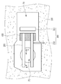
- FIG. 1 is a side view of a dismantling system of a nuclear reactor in accordance with one embodiment.
- FIG. 2 is a plan view of a dismantling system of a nuclear reactor according to one embodiment.
- FIG 3 is a view illustrating one step of dismantling a reactor using a dismantling system of a reactor according to one embodiment.
- FIG. 1 is a side view of a dismantling system of a nuclear reactor according to one embodiment
- FIG. 2 is a plan view of a dismantling system of a nuclear reactor according to one embodiment.
- the dismantling system of a nuclear reactor supports the bioprotective concrete 100, the reactor 10 in which the reactor 10 is located, and supports the reactor 10.
- a moving device 200 for moving a cutting device 300 for cutting the reactor 10, a leveling device 400 for keeping the moving device 200 horizontal, and a shielding film for blocking the bioprotective concrete 100 from the outside 500, and a dust collecting device 600 for collecting the radioactive dust 1 generated by the cutting device 300.
- the bioprotective concrete 100 has a first space P1 into which the reactor 10 is inserted, and a second space P2 connected to the first space P1 and dismantling the reactor 10. Can be.
- the second space P2 is larger than the first space P1 and is a more expanded space.
- the bottom portion 110 of the second space P2 may have a step. That is, the bottom part 110 of the second space P2 may include the first bottom part 110a and the second bottom part 110b at a position higher than the first bottom part 110a.
- the first space P1 may be located in the second bottom portion 110b.
- the mobile device 200 may move the nuclear reactor 10 horizontally disposed in the second space P2.
- the mobile device 200 may have a rail structure.
- the moving device 200 may linearly move the reactor 10 in a straight line direction A or rotate it in the rotation direction B.
- FIG. Thus, the cutting device 300 can be used to cut and disassemble the reactor portion at a desired position.
- the mobile device 200 may contact the second bottom portion 110b by overlapping the first space P1.
- the cutting device 300 may be located in the second space P2 and may be disassembled by cutting the reactor 10.
- the cutting device 300 may include a thermal cutting device, a mechanical cutting device such as a wire saw, or an electrical cutting device such as a laser.
- the cutting device 300 is not necessarily limited thereto, and various devices capable of cutting the reactor 10 are applicable.
- the cutting device 300 may include a cutting unit 310 for cutting the reactor 10 and a driving unit 320 for driving the cutting unit 310.
- the horizontal maintaining apparatus 400 may be positioned at the first bottom portion 110a of the second space P2 to support the mobile apparatus 200, thereby maintaining the horizontality of the mobile apparatus 200. That is, the height h2 of the horizontal holding device 400 may be the same as the height h1 of the first bottom portion 110a.
- the reactor 10 may be cut and dismantled by being seated in the second space P2 connected to the first space P1 using the horizontal holding device 400 and the moving device 200. It is possible to reduce the dismantling cost and the dismantling time since no additional expansion work is required to secure (P2).
- FIG 3 is a view illustrating one step of dismantling a reactor using a dismantling system of a reactor according to one embodiment.
- the reactor 10 located in the first space P1 is moved to the second space P2 by using a separate crane 700.
- the horizontal holding apparatus 400 is installed in the 1st bottom part 110a of the 2nd space P2, and the moving apparatus 200 is installed. Therefore, since the moving device 200 is supported by the leveling device 400 and the second bottom portion 110b, the moving device 200 is kept horizontal.
- the shielding film 500 may cover the second space P2 to block diffusion of the radioactive dust 1 to the outside.
- the shielding film 500 may include a plurality of ventilation parts 500a.
- the dust collecting device 600 may be connected to the plurality of ventilation units 500a to intensively collect the radioactive dust 1 collected through the ventilation unit 500a.
- the shielding film 500 shows that the radioactive dust 1 is diffused to the outside. You can block.
- the dust collecting device 600 is installed in the shielding film 500, but is not necessarily limited thereto and may be installed at various locations.
- the radioactive dust 1 generated by the cutting device 300 can be blocked from the outside by using the shielding film 500 and the dust collecting device 600, and it can be collected intensively using the ventilation unit 500a. In this way, the radioactive dust 1 can be minimized to contaminate peripheral equipment or to expose workers.
Landscapes
- Engineering & Computer Science (AREA)
- Physics & Mathematics (AREA)
- General Engineering & Computer Science (AREA)
- High Energy & Nuclear Physics (AREA)
- Plasma & Fusion (AREA)
- Health & Medical Sciences (AREA)
- Life Sciences & Earth Sciences (AREA)
- Biomedical Technology (AREA)
- General Health & Medical Sciences (AREA)
- Molecular Biology (AREA)
- Working Measures On Existing Buildindgs (AREA)
Abstract
일 실시예에 따른 원자로의 해체 시스템은 원자로가 삽입되는 제1 공간 및 상기 제1 공간에 연결되며 상기 제1 공간에서 확장되는 제2 공간을 가지는 생체 보호 콘크리트, 상기 제2 공간에 위치하며 상기 원자로를 이동시키는 이동 장치, 그리고 상기 제2 공간에 위치하며 상기 원자로를 절단하는 절단 장치를 포함한다.
Description
본 발명은 원자로의 해제 시스템에 관한 것이다.
전세계적으로 화석 에너지가 고갈됨에 따라, 주요한 에너지원으로서 원자력발전을 사용하고 있다. 이러한 원자력 발전에서 일반적으로 사용되는 가압 경수로형(Pressurized Water Reactor, PWR) 원자력 발전소는 원자로를 순환하는 1차 계통, 증기 발생기를 순환하는 2차 계통, 그리고 복수기를 순환하는 3차 계통으로 구성된다. 구체적으로 1차 계통에서는 원자로 속에 들어 있는 냉각재에 압력을 가해 150 기압 300℃정도를 유지하고, 2차 계통에서는 이 냉각재가 증기 발생기 세관을 통과하면서 증기 발생기 측의 물을 끓여 수증기를 만들어 터빈을 돌린다. 그리고, 3차 계통에서는 터빈을 돌리고 난 증기는 복수기를 통과하면서 다시 물이 되어 증기 발생기로 보낸다.
이러한 가압 경수로형 원자력 발전소의 원자로는 방사능으로 오염되어 있다. 따라서, 원자로를 절단하여 해체하는 경우 에어로졸(aerosol), 슬래그(slag) 등의 방사성 분진이 확산되어 주변 기기들을 오염시킬 수 있다.
본 실시예는 해체 공정 시 발생하는 방사성 분진에 의한 주변 기기들의 오염을 방지할 수 있는 원자로의 해체 시스템에 관한 것이다.
일 실시예에 따른 원자로의 해체 시스템은 원자로가 삽입되는 제1 공간 및 상기 제1 공간에 연결되며 상기 제1 공간에서 확장되는 제2 공간을 가지는 생체 보호 콘크리트, 상기 제2 공간에 위치하며 상기 원자로를 이동시키는 이동 장치, 그리고 상기 제2 공간에 위치하며 상기 원자로를 절단하는 절단 장치를 포함한다.
상기 제2 공간의 바닥부는 단차를 가지고, 상기 바닥부에 위치하여 상기 이동 장치의 수평을 유지하는 수평 유지 장치를 더 포함할 수 있다.
상기 제2 공간의 바닥부는 제1 바닥부, 상기 제1 바닥부보다 높은 위치의 제2 바닥부를 포함하고, 상기 수평 유지 장치는 상기 제1 바닥부에 위치하여 상기 이동 장치를 지지할 수 있다.
상기 이동 장치는 상기 원자로를 직선 이동시키거나 회전 이동시킬 수 있다.
상기 제2 바닥부에 상기 제1 공간이 위치하며, 상기 이동 장치는 상기 제1 공간과 중첩하여 상기 제2 바닥부와 접촉할 수 있다.
상기 제2 공간을 덮어 외부로 방사성 분진이 확산되는 것을 차단하는 차폐막을 더 포함하고, 상기 차폐막은 복수개의 환기부를 포함할 수 있다.
상기 복수개의 환기부에 연결되어 상기 방사성 분진을 포집하는 분진 포집 장치를 더 포함할 수 있다.
일 실시예에 따르면, 수평 유지 장치 및 이동 장치를 이용하여 제1 공간에 연결된 제2 공간 내에 안착시켜 원자로를 절단 및 해체할 수 있으므로, 제2 공간을 확보하기 위해 별도의 확장 공사가 필요하지 않으므로, 해체 비용 및 해체 시간을 절감할 수 있다.
또한, 제2 공간에서 수평 유지 장치 및 이동 장치를 이용하여 원자로를 지지한 상태에서 해체 공정을 진행하므로, 제1 공간에서 원자로를 해체하기 위한 별도의 인양 장치가 필요하지 않게 된다. 따라서, 해체 비용을 절감할 수 있다.
또한, 차폐막 및 분산 포집 장치를 이용하여 절단 장치에 의해 발생한 방사성 분진을 외부와 차단하고, 환기부를 이용하여 집중적으로 포집할 수 있으므로, 방사성 분진이 주변 기기를 오염시키거나, 작업자들을 피폭시키는 것을 최소화할 수 있다.
도 1은 일 실시예에 따른 원자로의 해체 시스템의 측면도이다.
도 2는 일 실시예에 따른 원자로의 해체 시스템의 평면도이다.
도 3은 일 실시예에 따른 원자로의 해체 시스템을 이용하여 원자로를 해체하는 일 단계를 도시한 도면이다.
이하, 첨부한 도면을 참고로 하여 본 발명의 여러 실시예들에 대하여 본 발명이 속하는 기술 분야에서 통상의 지식을 가진 자가 용이하게 실시할 수 있도록 상세히 설명한다. 본 발명은 여러 가지 상이한 형태로 구현될 수 있으며 여기에서 설명하는 실시예들에 한정되지 않는다.
본 발명을 명확하게 설명하기 위해서 설명과 관계없는 부분은 생략하였으며, 명세서 전체를 통하여 동일 또는 유사한 구성요소에 대해서는 동일한 참조 부호를 붙이도록 한다.
또한, 도면에서 나타난 각 구성의 크기 및 두께는 설명의 편의를 위해 임의로 나타내었으므로, 본 발명이 반드시 도시된 바에 한정되지 않는다.
도 1은 일 실시예에 따른 원자로의 해체 시스템의 측면도이고, 도 2는 일 실시예에 따른 원자로의 해체 시스템의 평면도이다.
도 1 및 도 2에 도시한 바와 같이, 일 실시예에 따른 원자로의 해체 시스템은 원자로(10)가 그 내부에 위치하는 생체 보호 콘크리트(100), 원자로(10)를 지지하며 원자로(10)를 이동시키는 이동 장치(200), 원자로(10)를 절단하는 절단 장치(300), 이동 장치(200)의 수평을 유지하는 수평 유지 장치(400), 생체 보호 콘크리트(100)를 외부와 차단하는 차폐막(500), 그리고 절단 장치(300)에 의해 발생하는 방사성 분진(1)을 포집하는 분진 포집 장치(600)를 포함한다.
생체 보호 콘크리트(100)는 원자로(10)가 삽입되는 제1 공간(P1), 그리고, 제1 공간(P1)과 연결되어 있으며 원자로(10)를 해체하는 공간인 제2 공간(P2)을 가질 수 있다. 제2 공간(P2)은 제1 공간(P1)보다 크고 보다 확장된 공간이다. 제2 공간(P2)의 바닥부(110)는 단차를 가질 수 있다. 즉, 제2 공간(P2)의 바닥부(110)는 제1 바닥부(110a), 제1 바닥부(110a)보다 높은 위치의 제2 바닥부(110b)를 포함할 수 있다. 제2 바닥부(110b)에는 제1 공간(P1)이 위치할 수 있다.
이동 장치(200)는 제2 공간(P2)에 위치하며 수평으로 배치된 원자로(10)를 이동시킬 수 있다. 이러한 이동 장치(200)는 레일 구조일 수 있다. 이동 장치(200)는 원자로(10)를 직선 방향(A)으로 직선 이동시키거나 회전 방향(B)으로 회전 이동시킬 수 있다. 따라서, 절단 장치(300)를 이용하여 원하는 위치의 원자로 부분을 절단하여 해체할 수 있다.
이러한 이동 장치(200)는 제1 공간(P1)과 중첩하여 제2 바닥부(110b)와 접촉할 수 있다.
절단 장치(300)는 제2 공간(P2)에 위치하며 원자로(10)를 절단하여 해체할 수 있다. 절단 장치(300)는 열적 절단 장치, 와이어 쏘(wire saw)와 같은 기계적 절단 장치, 또는 레이저(laser)와 같은 전기적 절단 장치 등을 포함할 수 있다. 그러나, 절단 장치(300)는 반드시 이에 한정되는 것은 아니며, 원자로(10)를 절단할 수 있는 다양한 장치가 적용 가능하다.
이러한 절단 장치(300)는 원자로(10)를 절단하는 절단부(310), 절단부(310)를 구동시키는 구동부(320)를 포함할 수 있다.
수평 유지 장치(400)는 제2 공간(P2)의 제1 바닥부(110a)에 위치하여 이동 장치(200)를 지지함으로써, 이동 장치(200)의 수평을 유지할 수 있다. 즉, 수평 유지 장치(400)의 높이(h2)는 제1 바닥부(110a)의 높이(h1)과 동일할 수 있다.
따라서, 수평 유지 장치(400)를 이용하여 수평으로 배치된 원자로(10)를 지지함으로써, 절단 장치(300)를 이용하여 원자로(10)를 절단할 수 있는 공간을 확보할 수 있다.
이와 같이, 수평 유지 장치(400) 및 이동 장치(200)를 이용하여 제1 공간(P1)에 연결된 제2 공간(P2) 내에 안착시켜 원자로(10)를 절단 및 해체할 수 있으므로, 제2 공간(P2)을 확보하기 위해 별도의 확장 공사가 필요하지 않으므로, 해체 비용 및 해체 시간을 절감할 수 있다.
또한, 제2 공간(P2)에서 수평 유지 장치(400) 및 이동 장치(200)를 이용하여 원자로(10)를 지지한 상태에서 해체 공정을 진행하므로, 제1 공간(P1)에서 원자로를 해체하기 위한 별도의 인양 장치가 필요하지 않게 된다. 따라서, 해체 비용을 절감할 수 있다.
도 3은 일 실시예에 따른 원자로의 해체 시스템을 이용하여 원자로를 해체하는 일 단계를 도시한 도면이다.
도 3에 도시한 바와 같이, 제1 공간(P1) 내에 위치하던 원자로(10)를 별도의 기중기(700)를 이용하여 제2 공간(P2)으로 이동시킨다. 그리고, 도 1에 도시한 바와 같이, 제2 공간(P2)의 제1 바닥부(110a)에 수평 유지 장치(400)를 설치하고, 이동 장치(200)를 설치한다. 따라서, 이동 장치(200)는 수평 유지 장치(400) 및 제2 바닥부(110b)에 의해 지지되므로 수평을 유지하게 된다.
한편, 차폐막(500)은 제2 공간(P2)을 덮어 외부로 방사성 분진(1)이 확산되는 것을 차단할 수 있다. 이러한 차폐막(500)은 복수개의 환기부(500a)를 포함할 수 있다.
분진 포집 장치(600)는 복수개의 환기부(500a)에 연결되어 환기부(500a)를 통해 포집된 방사성 분진(1)을 집중적으로 포집할 수 있다.
따라서, 절단 장치(300)를 이용하여 원자로(10)를 절단하여 슬래그, 흄가스, 에어로졸 등과 같은 방사성 분진(1)이 발생하여도 차폐막(500)은 방사성 분진(1)이 외부로 확산되는 것을 차단할 수 있다.
본 실시예에서는 분진 포집 장치(600)가 차폐막(500)에 설치되어 있으나, 반드시 이에 한정되는 것은 아니며 다양한 위치에 설치될 수 있다.
이와 같이, 차폐막(500) 및 분진 포집 장치(600)를 이용하여 절단 장치(300)에 의해 발생한 방사성 분진(1)을 외부와 차단하고, 환기부(500a)를 이용하여 집중적으로 포집할 수 있으므로, 방사성 분진(1)이 주변 기기를 오염시키거나, 작업자들을 피폭시키는 것을 최소화할 수 있다.
본 개시를 앞서 기재한 바에 따라 바람직한 실시예를 통해 설명하였지만, 본 발명은 이에 한정되지 않으며 다음에 기재하는 특허청구범위의 범위를 벗어나지 않는 한, 다양한 수정 및 변형이 가능하다는 것을 본 발명이 속하는 기술 분야에 종사하는 자들은 쉽게 이해할 것이다.
Claims (7)
- 원자로가 삽입되는 제1 공간 및 상기 제1 공간에 연결되며 상기 제1 공간에서 확장되는 제2 공간을 가지는 생체 보호 콘크리트,상기 제2 공간에 위치하며 상기 원자로를 이동시키는 이동 장치, 그리고상기 제2 공간에 위치하며 상기 원자로를 절단하는 절단 장치를 포함하는 원자로의 해체 시스템.
- 제1항에서,상기 제2 공간의 바닥부는 단차를 가지고,상기 바닥부에 위치하여 상기 이동 장치의 수평을 유지하는 수평 유지 장치를 더 포함하는 원자로의 해체 시스템.
- 제2항에서,상기 제2 공간의 바닥부는제1 바닥부, 상기 제1 바닥부보다 높은 위치의 제2 바닥부를 포함하고,상기 수평 유지 장치는 상기 제1 바닥부에 위치하여 상기 이동 장치를 지지하는 원자로의 해체 시스템.
- 제3항에서,상기 이동 장치는 상기 원자로를 직선 이동시키거나 회전 이동시키는 원자로의 해체 시스템.
- 제3항에서,상기 제2 바닥부에 상기 제1 공간이 위치하며,상기 이동 장치는 상기 제1 공간과 중첩하여 상기 제2 바닥부와 접촉하는 원자로의 해체 시스템.
- 제1항에서,상기 제2 공간을 덮어 외부로 방사성 분진이 확산되는 것을 차단하는 차폐막을 더 포함하고,상기 차폐막은 복수개의 환기부를 포함하는 원자로의 해체 시스템.
- 제6항에서,상기 복수개의 환기부에 연결되어 상기 방사성 분진을 포집하는 분진 포집 장치를 더 포함하는 원자로의 해체 시스템.
Priority Applications (3)
| Application Number | Priority Date | Filing Date | Title |
|---|---|---|---|
| EP19831295.1A EP3819916B1 (en) | 2018-07-06 | 2019-07-03 | Nuclear reactor dismantlement system |
| US17/257,913 US11823806B2 (en) | 2018-07-06 | 2019-07-03 | Nuclear reactor dismantlement system |
| JP2020570861A JP7068510B2 (ja) | 2018-07-06 | 2019-07-03 | 原子炉の解体システム |
Applications Claiming Priority (2)
| Application Number | Priority Date | Filing Date | Title |
|---|---|---|---|
| KR10-2018-0078940 | 2018-07-06 | ||
| KR1020180078940A KR102080909B1 (ko) | 2018-07-06 | 2018-07-06 | 원자로의 해체 시스템 |
Publications (1)
| Publication Number | Publication Date |
|---|---|
| WO2020009476A1 true WO2020009476A1 (ko) | 2020-01-09 |
Family
ID=69060113
Family Applications (1)
| Application Number | Title | Priority Date | Filing Date |
|---|---|---|---|
| PCT/KR2019/008152 Ceased WO2020009476A1 (ko) | 2018-07-06 | 2019-07-03 | 원자로의 해체 시스템 |
Country Status (5)
| Country | Link |
|---|---|
| US (1) | US11823806B2 (ko) |
| EP (1) | EP3819916B1 (ko) |
| JP (1) | JP7068510B2 (ko) |
| KR (1) | KR102080909B1 (ko) |
| WO (1) | WO2020009476A1 (ko) |
Cited By (2)
| Publication number | Priority date | Publication date | Assignee | Title |
|---|---|---|---|---|
| JP2022522696A (ja) * | 2019-03-08 | 2022-04-20 | コリア ハイドロ アンド ニュークリアー パワー カンパニー リミテッド | 原子力施設の解体方法 |
| US11697688B2 (en) | 2018-03-13 | 2023-07-11 | Tusk Therapeutics Ltd. | Anti-CD25 for tumour specific cell depletion |
Families Citing this family (1)
| Publication number | Priority date | Publication date | Assignee | Title |
|---|---|---|---|---|
| KR102345671B1 (ko) * | 2020-10-27 | 2021-12-29 | 한국수력원자력 주식회사 | 경수로형 원자로 해체 시스템 |
Citations (5)
| Publication number | Priority date | Publication date | Assignee | Title |
|---|---|---|---|---|
| JPH0875892A (ja) * | 1994-09-07 | 1996-03-22 | Toshiba Eng Co Ltd | 原子炉解体方法およびその装置 |
| JPH08240693A (ja) * | 1995-03-02 | 1996-09-17 | Hitachi Ltd | 原子炉圧力容器内構造物の撤去方法および切断方法 |
| US20020186806A1 (en) * | 1999-01-14 | 2002-12-12 | Hitachi, Ltd. | Method of carrying out large-sized apparatus |
| JP2012093181A (ja) * | 2010-10-26 | 2012-05-17 | Toshiba Corp | 原子炉圧力容器の解体方法及び解体装置 |
| KR101754538B1 (ko) * | 2016-08-02 | 2017-07-05 | 두산중공업 주식회사 | 원자로 용기 및 노내 구조물의 해체 방법 |
Family Cites Families (24)
| Publication number | Priority date | Publication date | Assignee | Title |
|---|---|---|---|---|
| EP0466533B1 (fr) * | 1990-06-27 | 1995-03-15 | Framatome | Procédé et dispositif de démantèlement d'un composant irradié d'un réacteur nucléaire par découpage de sa paroi |
| DE69208184T2 (de) * | 1991-08-26 | 1996-09-19 | Dymosha Kk | Verfahren zum Kernreaktorabbau |
| US5225150A (en) * | 1992-06-23 | 1993-07-06 | Westinghouse Electric Corp. | Integrated head package for top mounted nuclear instrumentation |
| US5274685A (en) | 1992-09-24 | 1993-12-28 | Siemens Power Corporation | Non-levitating PWR fuel assembly |
| JPH07159596A (ja) * | 1993-12-13 | 1995-06-23 | Ishikawajima Harima Heavy Ind Co Ltd | 原子炉遮蔽壁の解体方法及び原子炉遮蔽壁の解体装置 |
| FR2741991B1 (fr) * | 1995-11-30 | 1998-01-16 | Cogema | Procede et installation de demantelement a distance de structures irradiees |
| DE19639498A1 (de) * | 1996-09-26 | 1998-04-02 | Gutehoffnungshuette Man | Verfahren und Vorrichtung zum Entsorgen von Reaktordruckbehältern in Kernkraftwerken |
| KR100241139B1 (ko) * | 1997-03-17 | 2000-02-01 | 이종훈 | 에어 나이프를 이용한 이동식 분진비산억제장치 및 방법 |
| US6087546A (en) * | 1997-07-28 | 2000-07-11 | Griffiths; Geoffrey M. | Decommissioned reactor vessel package and method of making same |
| JP3663924B2 (ja) * | 1998-07-28 | 2005-06-22 | 株式会社日立製作所 | 原子炉の炉内構造物の取扱い方法及びその方法に用いる装置 |
| US20020176529A1 (en) * | 2002-05-14 | 2002-11-28 | Hitachi, Ltd. | Reactor vessel handling method |
| JP4644181B2 (ja) * | 2006-12-25 | 2011-03-02 | 東芝プラントシステム株式会社 | 原子炉構造物の切断設備 |
| US8189731B2 (en) * | 2009-07-07 | 2012-05-29 | John Jugl | Machinery system allowing replacement of old reactor with a new reactor in nuclear power electric generating station |
| US8873696B2 (en) * | 2010-03-27 | 2014-10-28 | Special Applications Technology, Inc. | Systems and methods for dismantling a nuclear reactor |
| US10854345B2 (en) * | 2012-03-02 | 2020-12-01 | Nuscale Power, Llc | Servicing a nuclear reactor module |
| US10014083B2 (en) * | 2012-05-02 | 2018-07-03 | Westinghouse Electric Company Llc | Method of refueling a nuclear reactor |
| US9318227B2 (en) * | 2013-01-15 | 2016-04-19 | Westinghouse Electric Company Llc | Apparatus and method for removing the upper internals from a nuclear reactor pressurized vessel |
| JP6491814B2 (ja) * | 2013-10-31 | 2019-03-27 | 日立Geニュークリア・エナジー株式会社 | 発電プラント解体時における汚染拡大防止方法及び発電プラント解体時の内部の調査方法 |
| KR101503288B1 (ko) | 2013-10-31 | 2015-03-18 | 티더블유앤씨(주) | 원자력시설용 비상 포집장치 |
| KR20150075822A (ko) | 2013-12-26 | 2015-07-06 | 한국원자력연구원 | 원자로용기 해체 작업용 벽면 이동형 로봇 시스템 |
| JP6704231B2 (ja) * | 2015-10-02 | 2020-06-03 | 三菱重工業株式会社 | 原子力プラントの解体方法 |
| JP6668747B2 (ja) * | 2015-12-25 | 2020-03-18 | 株式会社Ihi | 燃料回収方法 |
| KR102051398B1 (ko) * | 2017-09-05 | 2019-12-03 | 두산중공업 주식회사 | 원자로 용기의 해체 방법 |
| KR102027198B1 (ko) * | 2017-12-19 | 2019-10-01 | 두산중공업 주식회사 | 원자로 내부 구조물의 이송 장치 |
-
2018
- 2018-07-06 KR KR1020180078940A patent/KR102080909B1/ko active Active
-
2019
- 2019-07-03 WO PCT/KR2019/008152 patent/WO2020009476A1/ko not_active Ceased
- 2019-07-03 EP EP19831295.1A patent/EP3819916B1/en active Active
- 2019-07-03 JP JP2020570861A patent/JP7068510B2/ja active Active
- 2019-07-03 US US17/257,913 patent/US11823806B2/en active Active
Patent Citations (5)
| Publication number | Priority date | Publication date | Assignee | Title |
|---|---|---|---|---|
| JPH0875892A (ja) * | 1994-09-07 | 1996-03-22 | Toshiba Eng Co Ltd | 原子炉解体方法およびその装置 |
| JPH08240693A (ja) * | 1995-03-02 | 1996-09-17 | Hitachi Ltd | 原子炉圧力容器内構造物の撤去方法および切断方法 |
| US20020186806A1 (en) * | 1999-01-14 | 2002-12-12 | Hitachi, Ltd. | Method of carrying out large-sized apparatus |
| JP2012093181A (ja) * | 2010-10-26 | 2012-05-17 | Toshiba Corp | 原子炉圧力容器の解体方法及び解体装置 |
| KR101754538B1 (ko) * | 2016-08-02 | 2017-07-05 | 두산중공업 주식회사 | 원자로 용기 및 노내 구조물의 해체 방법 |
Non-Patent Citations (1)
| Title |
|---|
| See also references of EP3819916A4 * |
Cited By (4)
| Publication number | Priority date | Publication date | Assignee | Title |
|---|---|---|---|---|
| US11697688B2 (en) | 2018-03-13 | 2023-07-11 | Tusk Therapeutics Ltd. | Anti-CD25 for tumour specific cell depletion |
| JP2022522696A (ja) * | 2019-03-08 | 2022-04-20 | コリア ハイドロ アンド ニュークリアー パワー カンパニー リミテッド | 原子力施設の解体方法 |
| JP7137715B2 (ja) | 2019-03-08 | 2022-09-14 | コリア ハイドロ アンド ニュークリアー パワー カンパニー リミテッド | 原子力施設の解体方法 |
| US12002594B2 (en) | 2019-03-08 | 2024-06-04 | Korea Hydro & Nuclear Power Co., Ltd. | Method for decommissioning nuclear facilities |
Also Published As
| Publication number | Publication date |
|---|---|
| US11823806B2 (en) | 2023-11-21 |
| KR102080909B1 (ko) | 2020-02-24 |
| EP3819916A4 (en) | 2022-04-13 |
| US20210280330A1 (en) | 2021-09-09 |
| EP3819916A1 (en) | 2021-05-12 |
| JP7068510B2 (ja) | 2022-05-16 |
| JP2021529306A (ja) | 2021-10-28 |
| KR20200010674A (ko) | 2020-01-31 |
| EP3819916B1 (en) | 2025-04-23 |
Similar Documents
| Publication | Publication Date | Title |
|---|---|---|
| WO2020009476A1 (ko) | 원자로의 해체 시스템 | |
| CN104919534A (zh) | 用于从核反应堆加压容器移除上部内部构件的装置和方法 | |
| US7139359B2 (en) | Integrated head assembly for a nuclear reactor | |
| US4302290A (en) | Nuclear reactor vessel head equipment support structure | |
| EP2973597B1 (en) | Apparatus and method to inspect nuclear reactor components in the core annulus, core spray and feedwater sparger regions in a nuclear reactor | |
| WO2019203576A1 (ko) | 가압 경수로형 원자력 발전소의 생체 보호 콘크리트의 해체 방법 | |
| KR20200005515A (ko) | 원자로의 해체 시스템 | |
| FR2349925A1 (fr) | Machine de chargement d'un reacteur nucleaire | |
| WO2019203577A1 (ko) | 가압 경수로형 원자력 발전소의 생체 보호 콘크리트의 해체 및 제염 시스템및 방법 | |
| WO2020138930A1 (ko) | 원자력 시설의 해체 방법 | |
| WO2020009468A1 (ko) | 원자로의 해체 시스템 | |
| EP1993104B1 (en) | Method for dismantling heat exchanger installed in building for nuclear reactor | |
| WO2019203578A1 (ko) | 원자력 시설의 해체 방법 | |
| WO2020184897A1 (ko) | 원자력 시설의 해체 방법 | |
| WO2020013518A1 (ko) | 중수로 시설의 해체 방법 | |
| WO2020167043A1 (ko) | 원자력 시설의 수중 해체 방법 | |
| KR102035852B1 (ko) | 가압 경수로형 원자력 발전소의 생체 보호 콘크리트의 해체 방법 | |
| KR102164593B1 (ko) | 원자로의 해체 장치 | |
| US20050238130A1 (en) | Refueling work platform | |
| RU2786203C1 (ru) | Способ комплексного обследования блока защитных труб ядерного реактора и устройства для его осуществления | |
| WO2018062918A1 (ko) | 코어확산성능이 향상된 계단형 코어캐쳐 | |
| ES2541449A2 (es) | Sistemas y procedimientos para la disposición de uno o más componentes radiactivos de reactores nucleares de instalaciones nucleares | |
| EP3783623A1 (en) | Method for dismantling nuclear facility | |
| JPH0862369A (ja) | 原子炉圧力容器と炉内構造物取替時の搬入工法及び原子炉建屋 | |
| Grenlnger | Attn: J. _. Travls, Mawr |
Legal Events
| Date | Code | Title | Description |
|---|---|---|---|
| 121 | Ep: the epo has been informed by wipo that ep was designated in this application |
Ref document number: 19831295 Country of ref document: EP Kind code of ref document: A1 |
|
| ENP | Entry into the national phase |
Ref document number: 2020570861 Country of ref document: JP Kind code of ref document: A |
|
| NENP | Non-entry into the national phase |
Ref country code: DE |
|
| WWG | Wipo information: grant in national office |
Ref document number: 2019831295 Country of ref document: EP |