WO2020031686A1 - Raccord - Google Patents
Raccord Download PDFInfo
- Publication number
- WO2020031686A1 WO2020031686A1 PCT/JP2019/028864 JP2019028864W WO2020031686A1 WO 2020031686 A1 WO2020031686 A1 WO 2020031686A1 JP 2019028864 W JP2019028864 W JP 2019028864W WO 2020031686 A1 WO2020031686 A1 WO 2020031686A1
- Authority
- WO
- WIPO (PCT)
- Prior art keywords
- drive shaft
- driven shaft
- pair
- center tube
- shaft
- Prior art date
- Legal status (The legal status is an assumption and is not a legal conclusion. Google has not performed a legal analysis and makes no representation as to the accuracy of the status listed.)
- Ceased
Links
Images


Classifications
-
- F—MECHANICAL ENGINEERING; LIGHTING; HEATING; WEAPONS; BLASTING
- F16—ENGINEERING ELEMENTS AND UNITS; GENERAL MEASURES FOR PRODUCING AND MAINTAINING EFFECTIVE FUNCTIONING OF MACHINES OR INSTALLATIONS; THERMAL INSULATION IN GENERAL
- F16D—COUPLINGS FOR TRANSMITTING ROTATION; CLUTCHES; BRAKES
- F16D3/00—Yielding couplings, i.e. with means permitting movement between the connected parts during the drive
- F16D3/50—Yielding couplings, i.e. with means permitting movement between the connected parts during the drive with the coupling parts connected by one or more intermediate members
- F16D3/72—Yielding couplings, i.e. with means permitting movement between the connected parts during the drive with the coupling parts connected by one or more intermediate members with axially-spaced attachments to the coupling parts
- F16D3/74—Yielding couplings, i.e. with means permitting movement between the connected parts during the drive with the coupling parts connected by one or more intermediate members with axially-spaced attachments to the coupling parts the intermediate member or members being made of rubber or other rubber-like flexible material
-
- F—MECHANICAL ENGINEERING; LIGHTING; HEATING; WEAPONS; BLASTING
- F16—ENGINEERING ELEMENTS AND UNITS; GENERAL MEASURES FOR PRODUCING AND MAINTAINING EFFECTIVE FUNCTIONING OF MACHINES OR INSTALLATIONS; THERMAL INSULATION IN GENERAL
- F16D—COUPLINGS FOR TRANSMITTING ROTATION; CLUTCHES; BRAKES
- F16D1/00—Couplings for rigidly connecting two coaxial shafts or other movable machine elements
- F16D1/06—Couplings for rigidly connecting two coaxial shafts or other movable machine elements for attachment of a member on a shaft or on a shaft-end
- F16D1/08—Couplings for rigidly connecting two coaxial shafts or other movable machine elements for attachment of a member on a shaft or on a shaft-end with clamping hub; with hub and longitudinal key
- F16D1/09—Couplings for rigidly connecting two coaxial shafts or other movable machine elements for attachment of a member on a shaft or on a shaft-end with clamping hub; with hub and longitudinal key with radial clamping due to axial loading of at least one pair of conical surfaces
- F16D1/092—Couplings for rigidly connecting two coaxial shafts or other movable machine elements for attachment of a member on a shaft or on a shaft-end with clamping hub; with hub and longitudinal key with radial clamping due to axial loading of at least one pair of conical surfaces the pair of conical mating surfaces being provided on the coupled hub and shaft
-
- F—MECHANICAL ENGINEERING; LIGHTING; HEATING; WEAPONS; BLASTING
- F16—ENGINEERING ELEMENTS AND UNITS; GENERAL MEASURES FOR PRODUCING AND MAINTAINING EFFECTIVE FUNCTIONING OF MACHINES OR INSTALLATIONS; THERMAL INSULATION IN GENERAL
- F16D—COUPLINGS FOR TRANSMITTING ROTATION; CLUTCHES; BRAKES
- F16D3/00—Yielding couplings, i.e. with means permitting movement between the connected parts during the drive
- F16D3/50—Yielding couplings, i.e. with means permitting movement between the connected parts during the drive with the coupling parts connected by one or more intermediate members
- F16D3/72—Yielding couplings, i.e. with means permitting movement between the connected parts during the drive with the coupling parts connected by one or more intermediate members with axially-spaced attachments to the coupling parts
-
- F—MECHANICAL ENGINEERING; LIGHTING; HEATING; WEAPONS; BLASTING
- F16—ENGINEERING ELEMENTS AND UNITS; GENERAL MEASURES FOR PRODUCING AND MAINTAINING EFFECTIVE FUNCTIONING OF MACHINES OR INSTALLATIONS; THERMAL INSULATION IN GENERAL
- F16D—COUPLINGS FOR TRANSMITTING ROTATION; CLUTCHES; BRAKES
- F16D3/00—Yielding couplings, i.e. with means permitting movement between the connected parts during the drive
- F16D3/50—Yielding couplings, i.e. with means permitting movement between the connected parts during the drive with the coupling parts connected by one or more intermediate members
- F16D3/78—Yielding couplings, i.e. with means permitting movement between the connected parts during the drive with the coupling parts connected by one or more intermediate members shaped as an elastic disc or flat ring, arranged perpendicular to the axis of the coupling parts, different sets of spots of the disc or ring being attached to each coupling part, e.g. Hardy couplings
- F16D3/79—Yielding couplings, i.e. with means permitting movement between the connected parts during the drive with the coupling parts connected by one or more intermediate members shaped as an elastic disc or flat ring, arranged perpendicular to the axis of the coupling parts, different sets of spots of the disc or ring being attached to each coupling part, e.g. Hardy couplings the disc or ring being metallic
-
- F—MECHANICAL ENGINEERING; LIGHTING; HEATING; WEAPONS; BLASTING
- F16—ENGINEERING ELEMENTS AND UNITS; GENERAL MEASURES FOR PRODUCING AND MAINTAINING EFFECTIVE FUNCTIONING OF MACHINES OR INSTALLATIONS; THERMAL INSULATION IN GENERAL
- F16D—COUPLINGS FOR TRANSMITTING ROTATION; CLUTCHES; BRAKES
- F16D3/00—Yielding couplings, i.e. with means permitting movement between the connected parts during the drive
- F16D3/84—Shrouds, e.g. casings, covers; Sealing means specially adapted therefor
-
- F—MECHANICAL ENGINEERING; LIGHTING; HEATING; WEAPONS; BLASTING
- F16—ENGINEERING ELEMENTS AND UNITS; GENERAL MEASURES FOR PRODUCING AND MAINTAINING EFFECTIVE FUNCTIONING OF MACHINES OR INSTALLATIONS; THERMAL INSULATION IN GENERAL
- F16J—PISTONS; CYLINDERS; SEALINGS
- F16J15/00—Sealings
- F16J15/02—Sealings between relatively-stationary surfaces
- F16J15/06—Sealings between relatively-stationary surfaces with solid packing compressed between sealing surfaces
-
- F—MECHANICAL ENGINEERING; LIGHTING; HEATING; WEAPONS; BLASTING
- F16—ENGINEERING ELEMENTS AND UNITS; GENERAL MEASURES FOR PRODUCING AND MAINTAINING EFFECTIVE FUNCTIONING OF MACHINES OR INSTALLATIONS; THERMAL INSULATION IN GENERAL
- F16J—PISTONS; CYLINDERS; SEALINGS
- F16J15/00—Sealings
- F16J15/50—Sealings between relatively-movable members, by means of a sealing without relatively-moving surfaces, e.g. fluid-tight sealings for transmitting motion through a wall
- F16J15/52—Sealings between relatively-movable members, by means of a sealing without relatively-moving surfaces, e.g. fluid-tight sealings for transmitting motion through a wall by means of sealing bellows or diaphragms
-
- F—MECHANICAL ENGINEERING; LIGHTING; HEATING; WEAPONS; BLASTING
- F16—ENGINEERING ELEMENTS AND UNITS; GENERAL MEASURES FOR PRODUCING AND MAINTAINING EFFECTIVE FUNCTIONING OF MACHINES OR INSTALLATIONS; THERMAL INSULATION IN GENERAL
- F16J—PISTONS; CYLINDERS; SEALINGS
- F16J3/00—Diaphragms; Bellows; Bellows pistons
- F16J3/02—Diaphragms
-
- F—MECHANICAL ENGINEERING; LIGHTING; HEATING; WEAPONS; BLASTING
- F16—ENGINEERING ELEMENTS AND UNITS; GENERAL MEASURES FOR PRODUCING AND MAINTAINING EFFECTIVE FUNCTIONING OF MACHINES OR INSTALLATIONS; THERMAL INSULATION IN GENERAL
- F16D—COUPLINGS FOR TRANSMITTING ROTATION; CLUTCHES; BRAKES
- F16D2200/00—Materials; Production methods therefor
- F16D2200/0004—Materials; Production methods therefor metallic
-
- F—MECHANICAL ENGINEERING; LIGHTING; HEATING; WEAPONS; BLASTING
- F16—ENGINEERING ELEMENTS AND UNITS; GENERAL MEASURES FOR PRODUCING AND MAINTAINING EFFECTIVE FUNCTIONING OF MACHINES OR INSTALLATIONS; THERMAL INSULATION IN GENERAL
- F16D—COUPLINGS FOR TRANSMITTING ROTATION; CLUTCHES; BRAKES
- F16D2300/00—Special features for couplings or clutches
- F16D2300/02—Overheat protection, i.e. means for protection against overheating
- F16D2300/021—Cooling features not provided for in group F16D13/72 or F16D25/123, e.g. heat transfer details
- F16D2300/0212—Air cooling
-
- F—MECHANICAL ENGINEERING; LIGHTING; HEATING; WEAPONS; BLASTING
- F16—ENGINEERING ELEMENTS AND UNITS; GENERAL MEASURES FOR PRODUCING AND MAINTAINING EFFECTIVE FUNCTIONING OF MACHINES OR INSTALLATIONS; THERMAL INSULATION IN GENERAL
- F16D—COUPLINGS FOR TRANSMITTING ROTATION; CLUTCHES; BRAKES
- F16D2300/00—Special features for couplings or clutches
- F16D2300/02—Overheat protection, i.e. means for protection against overheating
- F16D2300/021—Cooling features not provided for in group F16D13/72 or F16D25/123, e.g. heat transfer details
- F16D2300/0214—Oil or fluid cooling
-
- F—MECHANICAL ENGINEERING; LIGHTING; HEATING; WEAPONS; BLASTING
- F16—ENGINEERING ELEMENTS AND UNITS; GENERAL MEASURES FOR PRODUCING AND MAINTAINING EFFECTIVE FUNCTIONING OF MACHINES OR INSTALLATIONS; THERMAL INSULATION IN GENERAL
- F16D—COUPLINGS FOR TRANSMITTING ROTATION; CLUTCHES; BRAKES
- F16D2300/00—Special features for couplings or clutches
- F16D2300/08—Details or arrangements of sealings not provided for in group F16D3/84
-
- F—MECHANICAL ENGINEERING; LIGHTING; HEATING; WEAPONS; BLASTING
- F16—ENGINEERING ELEMENTS AND UNITS; GENERAL MEASURES FOR PRODUCING AND MAINTAINING EFFECTIVE FUNCTIONING OF MACHINES OR INSTALLATIONS; THERMAL INSULATION IN GENERAL
- F16D—COUPLINGS FOR TRANSMITTING ROTATION; CLUTCHES; BRAKES
- F16D3/00—Yielding couplings, i.e. with means permitting movement between the connected parts during the drive
- F16D3/50—Yielding couplings, i.e. with means permitting movement between the connected parts during the drive with the coupling parts connected by one or more intermediate members
- F16D3/78—Yielding couplings, i.e. with means permitting movement between the connected parts during the drive with the coupling parts connected by one or more intermediate members shaped as an elastic disc or flat ring, arranged perpendicular to the axis of the coupling parts, different sets of spots of the disc or ring being attached to each coupling part, e.g. Hardy couplings
Definitions
- the present invention relates to a coupling that intervenes between two shafts and transmits rotational torque.
- the coupling is interposed between two shafts including a drive shaft and a driven shaft to transmit rotation, and at this time, absorbs misalignment between the two shafts.
- various types of such couplings and one of them is Japanese Utility Model Laid-Open No. 64-048432 (Patent Document 1) and Japanese Utility Model Laid-Open No. 01-11922 (Japanese Patent No.
- Patent Document 1 Japanese Utility Model Laid-Open No. 64-048432
- Japanese Utility Model Laid-Open No. 01-11922 Japanese Utility Model Laid-Open No. 01-11922
- a center tube is disposed between a pair of flanges facing each other, and the pair of flanges and the center tube are connected by a diaphragm made of a thin metal plate.
- One of the pair of flanges is connected to the drive shaft, and the other is connected to the driven shaft.
- the inner diameter of the diaphragm is fixed to both ends of the center tube, and the outer diameter is fixed to the flange.
- a guard is also fastened to the flange.
- the diaphragm couplings described in Patent Literatures 1 and 2 transmit rotational torque between a drive shaft and a driven shaft. At this time, misalignment such as axial displacement, axial displacement, and angular displacement due to deformation of the diaphragm is caused. Absorb.
- An object of the present invention is to efficiently cool a drive source of a system including a diaphragm coupling.
- the coupling of the present invention is a pair of connecting members provided respectively on the hollow drive shaft side and the driven shaft side, and is interposed between the pair of connecting members to absorb misalignment and to remove the misalignment from the drive shaft.
- a torque transmission portion that transmits torque to the driven shaft, a communication passage that connects a hollow region between the drive shaft and the driven shaft to form a flow space for a cooling fluid, and a space between the flow space and the external space.
- the cooling fluid can flow from the driven shaft to the drive shaft, the drive source can be efficiently cooled.
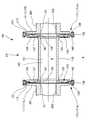
- FIG. 2 is a vertical cross-sectional view of the diaphragm coupling showing the embodiment.
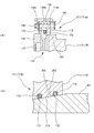
- (A) is an enlarged vertical cross-sectional view of an outer peripheral side seal portion
- (B) is an enlarged vertical cross-sectional view of an inner peripheral side seal portion.
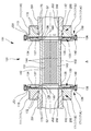
- FIG. 5 is a vertical cross-sectional view of a diaphragm coupling showing another embodiment.
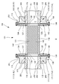
- FIG. 5 is a vertical cross-sectional view of a diaphragm coupling showing another embodiment.
- FIG. 5 is a vertical cross-sectional view of a diaphragm coupling showing another embodiment.
- FIG. 11 is a vertical sectional view of a diaphragm coupling showing still another embodiment.
- a first embodiment will be described with reference to FIGS. 1 and 2A and 2B.
- the diaphragm coupling 101 of the present embodiment is interposed between the two shafts including the drive shaft 201 and the driven shaft 301, and transmits rotational torque from the drive shaft 201 to the driven shaft 301. It absorbs misalignment with the driven shaft 301.
- the drive shaft 201 is driven and rotated by using, for example, a motor (not shown) as a drive source.
- both the drive shaft 201 and the driven shaft 301 are metal members having a hollow structure having inner holes 202 and 302. These inner holes 202 and 302 are provided coaxially with the drive shaft 201 and the driven shaft 301, and have a straight shape whose diameter does not change.
- the outer peripheral surfaces on the end side of the drive shaft 201 and the driven shaft 301 connected to the diaphragm coupling 101 are both inclined surfaces 203 and 303, and have a tapered shape whose diameter decreases toward the distal end. ing.
- the diaphragm coupling 101 is provided with a flexi unit 131 as a torque transmitting portion between a pair of flanges 111 as connecting members coaxially facing each other.
- the pair of flanges 111 that is, one flange 111L (the left side in FIG. 1) and the other flange 111R are both annular metal members, and have a connection hole 112 coaxially located at the center. I have.
- the connection hole 112 fits the drive shaft 201 and the driven shaft 301, and connects and fixes the flange 111 to the drive shaft 201 and the driven shaft 301. Therefore, the inner wall of the connection hole 112 is provided with a tapered shape in which the diameter increases toward the outside according to the outer shapes of the inclined surfaces 203 and 303 of the drive shaft 201 and the driven shaft 301.
- the drive shaft 201 and the flange 111L and the driven shaft 301 and the flange 111R that are fitted to each other are connected and fixed by hydraulic fitting as an example. That is, hydraulic pressure is applied to the flanges 111L and 111R to expand the diameters of the respective connection holes 112, and the hydraulic pressure is released after the drive shaft 201 and the driven shaft 301 are inserted into these connection holes 112. As a result, the diameter of the connection hole 112 returns to its original state, and the drive shaft 201 and the flange 111L and the driven shaft 301 and the flange 111R are connected and fixed. At this time, a taper fit occurs in which the tapered shapes given to the outer shapes of both members fit each other.
- the connection and fixing of the driving shaft 201 and the driven shaft 301 and the flange 111 that are fitted to each other may be realized by any means as long as the connection strength is maintained.
- the pair of flanges 111 (111L, 111R) connected and fixed to the drive shaft 201 and the driven shaft 301 form a flange-shaped mounting piece 113 from the outer peripheral portion at one end, which is the tip side of the drive shaft 201 and the driven shaft 301.
- the mounting piece 113 is used to fix the flexi unit 131.
- the flexi unit 131 includes a center tube 132, a diaphragm 133, and a guard 134.
- the center tube 132 is a hollow metal member having a cylindrical shape.
- the center tube 132 is located between a pair of flanges 111 (111L, 111R) and arranged coaxially with the flanges 111. What realizes such an arrangement of the center tube 132 is a pair of diaphragms 133.
- the diaphragm 133 is a disk-shaped metal member provided with a flexible portion 137 between the inner diameter portion 135 and the outer diameter portion 136, and has an opening 138 at the center. Therefore, the portion that continues to the opening 138 is the inner diameter portion 135.
- the bending portion 137 is thinner than the inner diameter portion 135 and the outer diameter portion 136, and the flexure portion 137 is formed when the outer diameter portion 136 and the inner diameter portion 135 are displaced in the axial direction, axially displaced, or angularly displaced. Causes deflection.
- the inner diameter portion 135 is integrally fixed to both ends of the center tube 132, and the outer diameter portion 136 is fixedly fastened to the pair of flanges 111. That is, the diaphragm 133 is coaxially fixed to the center tube 132 by joining the inner diameter portion 135 to both ends of the center tube 132. At this time, the center tube 132 and the inner diameter portion 135 of the diaphragm 133 are fixed rigidly and are airtightly integrated. Further, the diaphragm 133 has a bolt 139 penetrated through the outer diameter portion 136 and the mounting piece 113 provided on the pair of flanges 111, and is tightened and fixed by a nut 140. Due to such a structure, a plurality of bolt holes 136a, 113a are arranged at regular intervals in the outer diameter portion 136 of the diaphragm 133 and the mounting piece 113 of the flange 111.
- the guard 134 is a dish-shaped member having an opening 141 slightly larger in diameter than the center tube 132 at the center, and is disposed inside the pair of diaphragms 133 with the center tube 132 inserted into the opening 141. ing.
- the guard 134 is fixed to the flange 111 together with the pair of diaphragms 133. That is, the guard 134 is also provided with a bolt hole 134a in alignment with the plurality of bolt holes 136a and 113a provided in the outer diameter portion 136 of the diaphragm 133 and the mounting piece 113 of the flange 111, respectively.
- the guard 134 is fastened to the flange 111 together with the diaphragm 133 by the bolt 139 and the nut 140 by using the bolt holes 134a, and is fixed to the flange 111.
- the guard 134 thus fixed to the flange 111 together with the pair of diaphragms 133 has a gap therebetween so that the edge of the opening 141 faces the center tube 132. Therefore, when the flexure 137 of the diaphragm 133 bends to a certain degree or more, the guard 134 makes the edge of the opening 141 abut on the center tube 132 to protect the flexure 137 from excessive deformation.
- the guard 134 also suppresses the swing of the center tube 132 and prevents its protrusion when the diaphragm 133 is broken by an overload.
- the diaphragm coupling 101 of the present embodiment has a communication passage 151.
- the communication passage 151 connects a hollow area formed by the inner holes 202 and 302 between the drive shaft 201 and the driven shaft 301, and a cooling fluid from the inner hole 302 of the driven shaft 301 to the inner hole 202 of the drive shaft 201. Is formed.
- the communication passage 151 is formed by the inner hole 142 of the center tube 132 and the opening 138 provided in the diaphragm 133.
- the inner hole 142 of the center tube 132 has substantially the same diameter as the inner hole 202 of the drive shaft 201 and the inner hole 302 of the driven shaft 301, and has a slightly larger diameter except at both ends. Not equipped with straight shape.
- the opening 138 of the diaphragm 133 has substantially the same diameter as both ends of the inner hole 142 of the center tube 132, which has a slightly larger diameter than other regions.
- the diaphragm coupling 101, the drive shaft 201, and the driven shaft 301 are internally connected by the communication passage 151 having substantially the same diameter and the inner holes 202 and 302, and the cooling fluid, for example, the cooling water flows through the internal space.
- a circulation space F is formed.
- the diaphragm coupling 101 seals between the circulation space F and the external space A, and prevents leakage of the cooling fluid from the circulation space F.
- a portion 171 is provided.
- the seal portions 171 are provided in two different areas.
- One of the regions where the seal portion 171 is provided is a joint surface JS1 where the outer diameter portions 136 of the pair of diaphragms 133 and the attachment pieces 113 of the pair of flanges 111 (111L, 111R) are joined.
- the joining surface JS1 is provided on each of the diaphragm 133 side and the flange 111 side. However, for convenience of explanation, it is simply referred to as the joining surface JS1 unless it is determined which surface is provided.
- the seal portion 171 provided on the joint surface JS1 is referred to as “outer peripheral side seal portion 171A” in the present embodiment.
- Another area in which the seal portion 171 is provided is a joining surface JS2 where the drive shaft 201 and the driven shaft 301 and the flange are joined, that is, the drive shaft 201 and one flange 111L are joined, and the driven shaft 301
- it is simply referred to as a joint surface JS2 unless there is a problem as to which surface is provided.
- the seal portion 171 provided on the joint surface JS2 is referred to as “the inner peripheral side seal portion 171B” in the present embodiment.
- the seal part 171 seals the circulation space F and the external space A using the groove 172 and the O-ring 173.
- the O-ring 173 has a perfect circular cross section, and its diameter is set to be larger than the depth of the groove 172. A portion exceeding the depth dimension of the groove 172 becomes a crushing allowance, and the O-ring 173 seals the two members by the crushing allowance.
- the basic structure of the seal portion 171 is the same for the outer seal portion 171A and the inner seal portion 171B.
- the outer peripheral side seal portion 171A is provided with a groove 172 and an O-ring 173 on each joint surface JS1 of the pair of diaphragms 133 and the pair of flanges 111 (111L, 111R).
- the groove 172 is formed endlessly on the joint surface JS1 on the outer diameter portion 136 side of the diaphragm 133, and the O-ring 173 is housed in the groove 172. Therefore, when the diaphragm 133 and the flange 111 are joined by tightening the bolt 139 and the nut 140, the O-ring 173 is crushed by the joining surface JS1 on the mounting piece 113 side of the flange 111, and comes into close contact with each other, thereby exerting a sealing effect.
- the inner peripheral side seal portion 171B is provided with a groove 172 and an O-ring 173 on a joint surface JS2 between the drive shaft 201 and one flange 111L and a joint surface JS2 between the driven shaft 301 and the other flange 111R. ing.
- the groove 172 is formed endlessly in two on the joint surface JS2 on the side of the inclined surfaces 203, 303, and the O-ring 173 is housed in the two grooves 172, respectively.
- the diaphragm coupling 101 is mounted between the drive shaft 201 and the driven shaft 301 arranged in a straight line, and transmits the rotational torque from the drive shaft 201 to the driven shaft 301.
- the rotational torque from the drive shaft 201 is transmitted from the flange 111L on the drive shaft 201 side to the diaphragm 133 and the center tube 132, and is transmitted from the diaphragm 133 on the opposite side to the flange 111R on the driven shaft 301 side. It is transmitted to the shaft 301.
- the diaphragm coupling 101 In transmitting such a rotational torque, the diaphragm coupling 101 absorbs misalignment such as axial displacement, axial displacement, angular displacement, and the like generated between the drive shaft 201 and the driven shaft 301.
- a cooling fluid flow space F is provided from the inner hole 302 of the driven shaft 301 through the communication passage 151 of the diaphragm coupling 101 to the inner hole 202 of the drive shaft 201. Then, by flowing a cooling fluid, for example, cooling water through the circulation space F, it is possible to cool a drive source (not shown) of the drive shaft 201, for example, a motor or a turbine.
- a cooling fluid for example, cooling water
- a circulation pump (not shown) is installed at the end of the driven shaft 301, and the circulation pump is operated to forcibly generate a water flow toward the drive shaft 201 side.
- cooling water can flow through the inner hole 202 of the drive shaft 201 built in the motor, and the motor can be efficiently cooled.
- the gap G1 is provided between the drive shaft 201 and the flange 111L joined thereto and the diaphragm 133, and between the driven shaft 301 and the flange 111R joined thereto and the diaphragm 133.
- This gap G1 is indispensable for bending the diaphragm 133 in the axial direction and absorbing misalignment such as axial displacement between the drive shaft 201 and the driven shaft 301, while maintaining the flow space F When the cooling fluid is allowed to flow, the cooling fluid is allowed to enter.
- the cooling fluid that has entered the gap G1 permeates the joint surfaces JS1 and JS2. Therefore, the cooling fluid that has permeated the joint surfaces JS1 and JS2 may leak to the external space A. Therefore, in the present embodiment, the outer peripheral side seal portion 171A and the inner peripheral side seal portion 171B are provided on the joint surfaces JS1 and JS2, respectively. These seal portions 171 (171A, 171B) maintain the airtightness of the flow space F by the close contact of the O-ring 173 with the joint surfaces JS1, JS2. Therefore, according to the present embodiment, it is possible to prevent the leakage of the cooling fluid to the external space A. As a result, the adhesion of the fluid to the electric parts such as the motor and the wiring thereof is prevented, and the inconvenience when the electric system is wet with the fluid can be avoided.
- the outer peripheral side seal portion 171A of the seal portion 171 is provided on the joint surface JS1 between the outer diameter portion 136 of the pair of diaphragms 133 and the pair of flanges 111 (111L, 111R).
- An endless groove 172 and an O-ring 173 housed in the groove 172 are provided. Therefore, the seal portion 171 can be realized at a low cost with a simple structure.
- the set of the drive shaft 201 and the driven shaft 301 and the pair of flanges 111 (111L, 111R) that form a set with the drive shaft 201 and the driven shaft 301 are integrated by surface joining of separate parts. That is, the drive shaft 201 and the one flange 111L are separate parts, and are integrated by surface joining at the joining surface JS1.
- the driven shaft 301 and the other flange 111R are separate components, and are integrated by surface joining at the joining surface JS1.
- the inner peripheral side sealing portion 171B of the sealing portion 171 is a joint surface of a pair of two members integrated by surface joining of different parts, that is, the drive shaft 201 and one flange 111L. And an endless groove 172 provided on the joint surface JS2 between the driven shaft 301 and the other flange 111R, and an O-ring 173 housed in the groove 172. Therefore, the seal portion 171 can be realized at a low cost with a simple structure.
- the flexi unit 131 of the present embodiment includes a center tube 132, and is fixedly fastened to a pair of flanges 111 (111L, 111R) and an inner diameter portion 135 integrally fixed to both ends of the center tube 132, respectively.
- An outer diameter portion 136 is provided, and a pair of diaphragms 133 having a flexible portion 137 between the inner diameter portion 135 and the outer diameter portion 136 is provided.
- the communication passage 151 is formed by the inner hole 142 of the center tube 132 and the opening 138 provided in the diaphragm 133. Therefore, the communication passage 151 can be easily provided by utilizing the original structure of the flexi unit 131.
- This embodiment is an example of a configuration in which the two members of the drive shaft 201 and one flange 111L and the driven shaft 301 and the other flange 111R are integrally formed. .
- the drive shaft 201 and one flange 111L are integrally formed by cold forging.
- the drive shaft 201 and the one flange 111L are manufactured as an integral product by joining a metal disk-shaped annular member to an end of a metal pipe-shaped member. .
- the joining between the pipe-shaped member and the annular member is, for example, by welding.
- the cooling fluid does not permeate between the drive shaft 201 and the one flange 111L and between the driven shaft 301 and the other flange 111R. For this reason, since the inner peripheral side seal portion 171B is not required, the diaphragm coupling 101 does not have the inner peripheral side seal portion 171B.
- the present embodiment is an example of a configuration in which the concave and convex portions 143 that generate a pumping action are provided on the inner peripheral surface of the center tube 132.
- the concave and convex portions 143 are arranged on a spiral locus, and generate a pumping action of transferring a cooling fluid to a hollow region defined by the inner hole 202 of the drive shaft 201 by the rotation of the center tube 132.
- the uneven portion 143 is not provided continuously over the entire spiral locus, but is provided intermittently.
- the uneven shape of the uneven portion 143 is interrupted by the plurality of smooth surfaces 144 extending in the axial direction, and the shape is intermittent.
- the uneven portion 143 provided on the inner peripheral surface of the center tube 132 can be formed by a ridge, for example, and can be formed by a groove, as another example.
- the uneven portion 143 is formed by a ridge
- the original inner peripheral surface of the center tube 132 located between adjacent ridges forms a concave groove.
- the concave-convex portion 143 is formed by a concave groove
- the original inner peripheral surface of the center tube 132 located between adjacent concave grooves forms a ridge. Therefore, in any of the configuration examples, the uneven portion 143 gives the inner peripheral surface of the center tube 132 an uneven shape.
- the spiral trajectory on which the concave and convex portion 143 is formed has a direction in which it advances toward the drive shaft 201 in a counterclockwise direction when viewed from the driven shaft 301 side. Therefore, when the center tube 132 is rotated by the clockwise rotation of the drive shaft 201, a pumping action occurs in which the cooling fluid is transferred from the driven shaft 301 to the drive shaft 201.
- This embodiment is a configuration example in which the concave and convex portions 143 that generate a pumping action are provided on the inner peripheral surface of the center tube 132, as in the third embodiment.
- the difference from the third embodiment is that the uneven portion 143 is provided continuously over the entire spiral trajectory. Therefore, the uneven portion 143 has a spiral screw shape.
- the pumping action caused by the rotation of the center tube 132 is different from that of the third embodiment if the basic shape such as the width, depth, and spiral angle of the uneven portion 143 is the same. Become stronger. Therefore, the flow of the cooling fluid in the circulation space F can be created more efficiently.
- the present embodiment is a configuration example in which the hollow shaft 145 is disposed in the circulation space F on the assumption that the hollow region of the drive shaft 201 is a dead end and the abutment is the closed wall 204.
- the hollow shaft 145 is a hollow shaft whose both ends are opened.
- a gap G2 is opened in the closed wall 204 in the hollow area of the drive shaft 201 so that the opening 146 on one end faces, and the hollow shaft 145 is connected to the communication passage 151 of the diaphragm coupling 101.
- the other end extends to the hollow region of the driven shaft 301.
- the hollow shaft 145 divides the inside of the distribution space F into two sections, and creates a forward path FF and a return path FR.
- the outward path FF is formed by the gap between the inner peripheral wall of the inner hole 202 of the drive shaft 201, the communication passage 151 of the diaphragm coupling 101, and the inner hole 302 of the driven shaft 301 and the outer peripheral surface of the hollow shaft 145.
- G3 is formed.
- the return path FR is formed by the inner hole 147 of the hollow shaft 145.
- the cooling fluid can flow through the flow space F even if the flow space F on the drive shaft 201 side is dead-ended.
- the cooling water is exemplified as the cooling fluid.
- the present invention is not limited to this, and various cooling fluids such as oil and gas can be used.
Landscapes
- Engineering & Computer Science (AREA)
- General Engineering & Computer Science (AREA)
- Mechanical Engineering (AREA)
- Mechanical Sealing (AREA)
- Sealing Devices (AREA)
- Motor Or Generator Cooling System (AREA)
- Structures Of Non-Positive Displacement Pumps (AREA)
Abstract
Priority Applications (5)
| Application Number | Priority Date | Filing Date | Title |
|---|---|---|---|
| JP2020536437A JP7237970B2 (ja) | 2018-08-09 | 2019-07-23 | カップリング |
| CN201980043205.9A CN112368485B (zh) | 2018-08-09 | 2019-07-23 | 联轴器 |
| EP19846573.4A EP3835608B1 (fr) | 2018-08-09 | 2019-07-23 | Raccord |
| KR1020217000103A KR102565890B1 (ko) | 2018-08-09 | 2019-07-23 | 커플링 |
| US17/258,669 US11879506B2 (en) | 2018-08-09 | 2019-07-23 | Coupling |
Applications Claiming Priority (2)
| Application Number | Priority Date | Filing Date | Title |
|---|---|---|---|
| JP2018-150474 | 2018-08-09 | ||
| JP2018150474 | 2018-08-09 |
Publications (1)
| Publication Number | Publication Date |
|---|---|
| WO2020031686A1 true WO2020031686A1 (fr) | 2020-02-13 |
Family
ID=69414108
Family Applications (1)
| Application Number | Title | Priority Date | Filing Date |
|---|---|---|---|
| PCT/JP2019/028864 Ceased WO2020031686A1 (fr) | 2018-08-09 | 2019-07-23 | Raccord |
Country Status (6)
| Country | Link |
|---|---|
| US (1) | US11879506B2 (fr) |
| EP (1) | EP3835608B1 (fr) |
| JP (1) | JP7237970B2 (fr) |
| KR (1) | KR102565890B1 (fr) |
| CN (1) | CN112368485B (fr) |
| WO (1) | WO2020031686A1 (fr) |
Citations (8)
| Publication number | Priority date | Publication date | Assignee | Title |
|---|---|---|---|---|
| JPS61192931A (ja) * | 1984-11-29 | 1986-08-27 | ア−テ−エ−ツエ−−バイス コマンデイトゲゼルシヤフト | 全スチ−ル製たわみ継ぎ手 |
| JPS6318629U (fr) * | 1986-07-23 | 1988-02-06 | ||
| JPS6448432U (fr) | 1987-09-21 | 1989-03-24 | ||
| JPH01119922U (fr) | 1988-02-10 | 1989-08-14 | ||
| JP2000514160A (ja) * | 1996-06-21 | 2000-10-24 | ルーカス エアロスペース パワー トランスミッション、ア ディビジョン オブ ルーカス ウェスタン、インコーポレイテッド | 多角形を利用する非溶接継手 |
| EP1433970A1 (fr) * | 2002-12-27 | 2004-06-30 | Kop-Flex, Inc. | Accouplement d'arbres avec éléments souples |
| JP2010519479A (ja) * | 2007-02-21 | 2010-06-03 | ムーグ ウォルヴァーハンプトン リミテッド | ダイアフラムカップリング |
| JP2017032081A (ja) * | 2015-08-03 | 2017-02-09 | イーグル工業株式会社 | ダイアフラムカップリング |
Family Cites Families (15)
| Publication number | Priority date | Publication date | Assignee | Title |
|---|---|---|---|---|
| GB594550A (en) * | 1945-01-16 | 1947-11-13 | Power Jets Res & Dev Ltd | Improvements in or relating to flexible couplings for shafts and the like |
| US2870617A (en) | 1954-04-26 | 1959-01-27 | Melville F Peters | Control of torque and fluid flow in sealed drives |
| US3368369A (en) * | 1966-03-21 | 1968-02-13 | Koppers Co Inc | Sealed gear coupling |
| JPS5129387Y2 (fr) * | 1971-07-14 | 1976-07-24 | ||
| US4411634A (en) * | 1980-11-10 | 1983-10-25 | The Bendix Corporation | Flexible coupling having molded plastic flexible diaphragms |
| JPS6259325U (fr) | 1985-05-20 | 1987-04-13 | ||
| JPS62143822U (fr) * | 1986-03-05 | 1987-09-10 | ||
| JPS6448432A (en) | 1987-08-19 | 1989-02-22 | Hitachi Ltd | Molding die and manufacture of semiconductor device by using said die |
| JPH01119922A (ja) | 1987-11-04 | 1989-05-12 | Toshiba Corp | 光学式ディスク再生装置のフォーカスサーチ回路 |
| JPH0191126U (fr) * | 1987-12-09 | 1989-06-15 | ||
| JPH01118228U (fr) * | 1988-02-04 | 1989-08-10 | ||
| US20070049379A1 (en) | 2005-08-30 | 2007-03-01 | Simmonds Precision Products, Inc. | Flexible coupling device |
| DE102006004836A1 (de) * | 2005-11-17 | 2007-05-24 | Frank Eckert | Organic Rankine Zyklus (ORC)- Turbogenerator |
| EP2110572A1 (fr) * | 2008-04-16 | 2009-10-21 | Siemens Aktiengesellschaft | Refroidissement d'empilage de tôles du rotor d'un palier magnétique |
| CN201351690Y (zh) * | 2009-01-23 | 2009-11-25 | 沈阳华科技贸有限责任公司 | 膜盘联轴器 |
-
2019
- 2019-07-23 CN CN201980043205.9A patent/CN112368485B/zh active Active
- 2019-07-23 KR KR1020217000103A patent/KR102565890B1/ko active Active
- 2019-07-23 EP EP19846573.4A patent/EP3835608B1/fr active Active
- 2019-07-23 JP JP2020536437A patent/JP7237970B2/ja active Active
- 2019-07-23 WO PCT/JP2019/028864 patent/WO2020031686A1/fr not_active Ceased
- 2019-07-23 US US17/258,669 patent/US11879506B2/en active Active
Patent Citations (8)
| Publication number | Priority date | Publication date | Assignee | Title |
|---|---|---|---|---|
| JPS61192931A (ja) * | 1984-11-29 | 1986-08-27 | ア−テ−エ−ツエ−−バイス コマンデイトゲゼルシヤフト | 全スチ−ル製たわみ継ぎ手 |
| JPS6318629U (fr) * | 1986-07-23 | 1988-02-06 | ||
| JPS6448432U (fr) | 1987-09-21 | 1989-03-24 | ||
| JPH01119922U (fr) | 1988-02-10 | 1989-08-14 | ||
| JP2000514160A (ja) * | 1996-06-21 | 2000-10-24 | ルーカス エアロスペース パワー トランスミッション、ア ディビジョン オブ ルーカス ウェスタン、インコーポレイテッド | 多角形を利用する非溶接継手 |
| EP1433970A1 (fr) * | 2002-12-27 | 2004-06-30 | Kop-Flex, Inc. | Accouplement d'arbres avec éléments souples |
| JP2010519479A (ja) * | 2007-02-21 | 2010-06-03 | ムーグ ウォルヴァーハンプトン リミテッド | ダイアフラムカップリング |
| JP2017032081A (ja) * | 2015-08-03 | 2017-02-09 | イーグル工業株式会社 | ダイアフラムカップリング |
Also Published As
| Publication number | Publication date |
|---|---|
| KR20210016028A (ko) | 2021-02-10 |
| EP3835608C0 (fr) | 2024-07-03 |
| US20210270327A1 (en) | 2021-09-02 |
| EP3835608A1 (fr) | 2021-06-16 |
| EP3835608B1 (fr) | 2024-07-03 |
| KR102565890B1 (ko) | 2023-08-09 |
| EP3835608A4 (fr) | 2022-05-11 |
| JP7237970B2 (ja) | 2023-03-13 |
| CN112368485A (zh) | 2021-02-12 |
| JPWO2020031686A1 (ja) | 2021-08-10 |
| CN112368485B (zh) | 2023-03-28 |
| US11879506B2 (en) | 2024-01-23 |
Similar Documents
| Publication | Publication Date | Title |
|---|---|---|
| JP4627240B2 (ja) | 4輪駆動用変速機ハウジング構造 | |
| US8403627B2 (en) | Water pump for pumping coolant in a low temperature and in a high temperature circuit | |
| JP2005524044A (ja) | 自動車用の排気熱交換器 | |
| JP4102706B2 (ja) | 熱交換機能を備えたスクリュー、混練機および押出機 | |
| JP4268913B2 (ja) | 流体機器どうしの接続構造 | |
| WO2020031686A1 (fr) | Raccord | |
| US20160131244A1 (en) | Cooled Gear Housing Assembly | |
| KR100445581B1 (ko) | 로터리펌프 | |
| JP5691087B2 (ja) | 緩衝部材、軸連結構造体、及び一軸偏心ねじポンプ | |
| US20250239916A1 (en) | Transmission mechanism having cooling flow path and e-axle driving system | |
| WO2020008822A1 (fr) | Soupape de commande, soupape de régulation de débit et structure de raccordement à deux éléments | |
| KR101028112B1 (ko) | 벨로우즈 타입의 메카니컬 실링 조립체 | |
| JP3221706U (ja) | ボールねじの冷却システム | |
| US4472154A (en) | Drive arrangement for transferring torque between two non-aligned shafts | |
| JP2013224677A (ja) | 管継手 | |
| US718157A (en) | Pipe flange or coupling. | |
| JP2021042890A (ja) | 熱交換器 | |
| JP3854058B2 (ja) | ギヤポンプ | |
| KR102489850B1 (ko) | 농기계용 변속기 | |
| EP3794243A1 (fr) | Dispositif de transmission de couple a frottements reduits | |
| JP3895537B2 (ja) | ギヤポンプ | |
| JP2006170262A (ja) | 管の接合構造 | |
| CN116642381B (zh) | 飞行体冷却装置 | |
| EP3830401B1 (fr) | Échangeur thermique pour turbomachine | |
| JPH0579834B2 (fr) |
Legal Events
| Date | Code | Title | Description |
|---|---|---|---|
| 121 | Ep: the epo has been informed by wipo that ep was designated in this application |
Ref document number: 19846573 Country of ref document: EP Kind code of ref document: A1 |
|
| ENP | Entry into the national phase |
Ref document number: 20217000103 Country of ref document: KR Kind code of ref document: A |
|
| ENP | Entry into the national phase |
Ref document number: 2020536437 Country of ref document: JP Kind code of ref document: A |
|
| NENP | Non-entry into the national phase |
Ref country code: DE |
|
| ENP | Entry into the national phase |
Ref document number: 2019846573 Country of ref document: EP Effective date: 20210309 |