WO2020071367A1 - Dispositif de séparation d'un mélange dans un liquide - Google Patents
Dispositif de séparation d'un mélange dans un liquideInfo
- Publication number
- WO2020071367A1 WO2020071367A1 PCT/JP2019/038754 JP2019038754W WO2020071367A1 WO 2020071367 A1 WO2020071367 A1 WO 2020071367A1 JP 2019038754 W JP2019038754 W JP 2019038754W WO 2020071367 A1 WO2020071367 A1 WO 2020071367A1
- Authority
- WO
- WIPO (PCT)
- Prior art keywords
- evaporator
- mixture
- liquid
- liquid containing
- control valve
- Prior art date
- Legal status (The legal status is an assumption and is not a legal conclusion. Google has not performed a legal analysis and makes no representation as to the accuracy of the status listed.)
- Ceased
Links
Images

Classifications
-
- B—PERFORMING OPERATIONS; TRANSPORTING
- B01—PHYSICAL OR CHEMICAL PROCESSES OR APPARATUS IN GENERAL
- B01D—SEPARATION
- B01D1/00—Evaporating
-
- B—PERFORMING OPERATIONS; TRANSPORTING
- B01—PHYSICAL OR CHEMICAL PROCESSES OR APPARATUS IN GENERAL
- B01D—SEPARATION
- B01D3/00—Distillation or related exchange processes in which liquids are contacted with gaseous media, e.g. stripping
-
- B—PERFORMING OPERATIONS; TRANSPORTING
- B01—PHYSICAL OR CHEMICAL PROCESSES OR APPARATUS IN GENERAL
- B01D—SEPARATION
- B01D5/00—Condensation of vapours; Recovering volatile solvents by condensation
Definitions
- the present invention relates to an apparatus for separating a mixture contained in a liquid by a difference in boiling point by distillation under reduced pressure, and a substance that is vaporized by arranging a heat exchanger between an evaporator equipped with a heating device and a vacuum pump.
- a heat exchanger between an evaporator equipped with a heating device and a vacuum pump.
- Patent Documents 3 and 4 there is a method in which a liquid is placed in a depressurized container, heated, vaporized and condensed, and separated from a mixture in the liquid.
- a device that can separate and remove the mixture contained in the source fluid using only physical methods such as centrifugal force, inertial force, gravity, pressure difference, etc. has the characteristics of simple structure and easy maintenance and maintenance. If provided, the separation capacity may be reduced, and the apparatus may be increased in size.
- a pump and a pump for transferring the liquid into the evaporator are used.
- the present invention reduces the amount of heat supplied to the liquid containing the mixture by the heating device installed in the evaporator to heat the mixture contained in the fluid (energy saving), and reduces the amount of the liquid containing the mixture flowing into the evaporator.
- the control valve (2) By installing the control valve (2) in the middle of the pipe flowing into the evaporator, the structure of interlocking the level sensor and the control valve (2) to control the amount of the liquid containing the mixture remaining in the evaporator is simple.
- a device that has a structure and function that does not require power for example, a transfer pump) when transferring a liquid containing a mixture into an evaporator, while performing only with a device having a structure and function having reliability and durability. The purpose is to do.
- the invention according to claim 1 is a flow control valve installed in a pipe (7a, 7b, 7c) flowing into an evaporator (1) in which a mixture in a liquid containing the mixture is separated due to a difference in boiling point.
- a control valve (2) wherein the liquid containing the mixture flows into the evaporator (1) and is throttled when the amount of the liquid exceeds a set value, and the amount corresponding to the amount of evaporation of the liquid containing the mixture is evaporated.
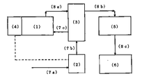
- a control valve (2) for maintaining a certain opening so as to flow into the vessel (1) a heat exchanger (3) connected to the control valve (2) via a pipe (7b), An evaporator (1) connected to the exchanger (3) via a pipe (7c), a level sensor (4) installed on the evaporator (1), and a pipe (8a) connected to the evaporator (1).
- a vacuum connected to the heat exchanger (3) via a pipe (8b).
- a pump (5) characterized in that it is constructed from the condenser (6) connected through a pipe (8c) to the vacuum pump (5).
- a second aspect of the present invention is a flow control valve that is provided in a middle of a pipe through which a liquid containing a mixture and a level sensor provided in the evaporator flows into the evaporator while a negative pressure is provided in the evaporator.
- the invention according to claim 3 is an apparatus for separating a mixture contained in a liquid by a difference in boiling point, wherein a vacuum pump (5) capable of setting a pressure in an evaporator (1) to an arbitrary degree of vacuum; A heating device installed in the evaporator (1) capable of arbitrarily setting the temperature in the evaporator (1), wherein the pressure and temperature of the liquid containing the mixture in the evaporator (1) are vaporized by the liquid. It can be set to an optimum value.
- the invention according to claim 4 is an apparatus for separating a mixture contained in a liquid by a difference in boiling point, wherein a heat exchanger (3) is provided between an evaporator (1) and a vacuum pump (5).
- the heat exchanger has a function of supplying the amount of heat (latent heat and sensible heat) held by the vaporized components to the liquid containing the mixture flowing into the evaporator. It is characterized in that an effect of reducing the amount of heat supplied to the liquid containing the mixture (energy saving effect) can be obtained.
- the present invention is a storage device for separating contaminants in a liquid by a difference in boiling point, and by placing a heat exchanger between an evaporator and a vacuum pump, the amount of heat held by vaporized components can be effectively utilized (
- the liquid containing the mixture is transferred into the evaporator by linking the level sensor installed in the evaporator and the control valve (2) installed in the piping for the liquid to flow into the evaporator.
- structure that does not require power to be simple it is possible to maintain and maintenance to provide a mixed-removing device of easy (close to the maintenance-free) of liquid.
- FIG. 1 is a flowchart showing an example of steps of an apparatus for separating and removing a mixture contained in a fluid according to an embodiment of the present invention.
- the liquid containing the mixture in the evaporator is detected by a level sensor installed in the evaporator.
- the control valve (2) which is a flow control valve installed in the middle of the pipe through which the liquid containing the mixture flows into the evaporator, ) Opens and the liquid containing the mixture flows into the evaporator.
- the fluid naturally flows in due to the pressure difference.
- the liquid containing the mixture via the control valve is heated in a heat exchanger.
- the liquid containing the heated mixture flows into the evaporator, and when the amount exceeds the set value, the control valve is throttled.
- an amount corresponding to the amount of evaporation of the liquid containing the mixture flows into the evaporator, and the control valve maintains a certain opening.
- the liquid containing the mixture that has flowed into the evaporator is heated by a heating device installed in the evaporator, and is vaporized at a boiling point corresponding to the negative pressure of the vacuum pump and the high temperature of the heating device. And separate from the mixture.
- the gaseous component exchanges heat with the liquid containing the mixture supplied to the evaporator in the heat exchanger, and as the temperature decreases, a part of the gas condenses and releases heat of condensation, so that a relatively low temperature is obtained. Heat is supplied to the liquid containing the mixture to increase the temperature.
- the gaseous component that has passed through the heat exchanger reaches the condenser via a vacuum pump and is liquefied by being cooled.
- FIG. 2 is a block diagram showing an example of a configuration of a device for separating and removing a mixture contained in a fluid according to an embodiment of the present invention.
- the liquid mixture removal device is a flow control valve installed in the middle of a pipe (7a, 7b, 7c) flowing into an evaporator (1) in which a mixture in a liquid containing the mixture is separated due to a difference in boiling point.
- the vacuum pump (5) is connected to the exchanger (3) via a pipe (8b), and the condenser (6) is connected to the vacuum pump (5) via a pipe (8c).
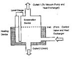
- FIG. 3 is a conceptual diagram showing an example of an evaporator which is a main part of a device for separating a mixture in a liquid contained in a liquid according to an embodiment of the present invention.
- the liquid containing the mixture that has flowed into the pipe leading to the evaporator by the control valve (2), which is a flow control valve, is heated by the heat exchanger, and then flows into the evaporator from the inlet provided at the lower part of the evaporator. .
- the liquid containing the mixture that has flowed into the evaporator is heated by a heating device installed in the evaporator, and is vaporized at a temperature according to the pressure (negative pressure) in the evaporator set by a vacuum pump, into the liquid. Separated from contained mixture.
- the vaporized components are sucked by the vacuum pump, flow out of the outlet 1 and reach the condenser via the heat exchanger.
- the fluid containing the mixture is vaporized in the evaporator due to the difference in boiling point, and liquefied in the condenser, thereby being continuously separated from the mixture.
- the present invention is applicable to a case where a mixture contained in a liquid is effectively separated.
Landscapes
- Chemical & Material Sciences (AREA)
- Chemical Kinetics & Catalysis (AREA)
- Vaporization, Distillation, Condensation, Sublimation, And Cold Traps (AREA)
Abstract
Ce dispositif de séparation d'un mélange dans un liquide est caractérisé en ce qu'il comprend : une vanne de commande (2) qui est une vanne de régulation de débit disposée en un point le long de la tuyauterie (7a,7b, 7c) s'écoulant vers un évaporateur (1) le mélange dans le liquide contenant un mélange étant séparé par une différence dans le point d'ébullition, et qui est étranglé si le débit du liquide contenant un mélange s'écoulant dans l'évaporateur (1) atteint ou dépasse une valeur définie et maintient un certain degré d'ouverture de telle sorte que le liquide contenant un mélange s'écoule dans l'évaporateur (1) dans une quantité correspondant à la quantité d'évaporation du liquide contenant un mélange; un échangeur de chaleur (3) qui est relié à la vanne de commande (2) par l'intermédiaire de la tuyauterie (7b); l'évaporateur (1) qui est relié à l'échangeur de chaleur (3) par l'intermédiaire de la tuyauterie (7c); un capteur de niveau (4) qui est disposé dans l'évaporateur (1); l'échangeur de chaleur (3) qui est relié à l'évaporateur (1) par l'intermédiaire d'une tuyauterie (8a); une pompe à vide (5) qui est relié à l'échangeur de chaleur (3) par l'intermédiaire d'une tuyauterie (8b); et un condenseur (6) qui est relié à la pompe à vide (5) par l'intermédiaire d'une tuyauterie (8c).
Applications Claiming Priority (2)
| Application Number | Priority Date | Filing Date | Title |
|---|---|---|---|
| JP2018-187577 | 2018-10-02 | ||
| JP2018187577A JP6593729B1 (ja) | 2018-10-02 | 2018-10-02 | 液体中の混合物分離装置 |
Publications (1)
| Publication Number | Publication Date |
|---|---|
| WO2020071367A1 true WO2020071367A1 (fr) | 2020-04-09 |
Family
ID=68314085
Family Applications (1)
| Application Number | Title | Priority Date | Filing Date |
|---|---|---|---|
| PCT/JP2019/038754 Ceased WO2020071367A1 (fr) | 2018-10-02 | 2019-10-01 | Dispositif de séparation d'un mélange dans un liquide |
Country Status (2)
| Country | Link |
|---|---|
| JP (1) | JP6593729B1 (fr) |
| WO (1) | WO2020071367A1 (fr) |
Cited By (1)
| Publication number | Priority date | Publication date | Assignee | Title |
|---|---|---|---|---|
| CN116952552A (zh) * | 2023-06-08 | 2023-10-27 | 德安福(天津)汽车技术有限公司 | 低温真空循环法 |
Families Citing this family (2)
| Publication number | Priority date | Publication date | Assignee | Title |
|---|---|---|---|---|
| JP7597373B2 (ja) * | 2021-07-21 | 2024-12-10 | 和幸 前田 | 液体中の混合物を分離する装置と方法 |
| JP7716159B1 (ja) * | 2025-05-26 | 2025-07-31 | 和幸 前田 | 減圧蒸留装置と減圧蒸留方法 |
Citations (6)
| Publication number | Priority date | Publication date | Assignee | Title |
|---|---|---|---|---|
| JPH0631103A (ja) * | 1992-07-18 | 1994-02-08 | Marusan Shokai:Kk | ワーク洗浄用の可燃性溶剤の真空蒸留方法および真空蒸留機 |
| JPH06269603A (ja) * | 1993-03-19 | 1994-09-27 | Tsukada Fuainesu:Kk | 真空蒸留装置 |
| WO1995006504A1 (fr) * | 1993-08-30 | 1995-03-09 | Kabushiki Kaisha Toshiba | Procede et appareil de distillation sous pression reduite |
| JPH09313803A (ja) * | 1996-05-27 | 1997-12-09 | Keiji Nakaya | 汚染溶剤液の精製方法 |
| JP2002282844A (ja) * | 2001-03-28 | 2002-10-02 | Sasakura Engineering Co Ltd | 廃水中の揮発性有機化合物を分離する方法 |
| JP2004337657A (ja) * | 2003-05-13 | 2004-12-02 | Sasakura Engineering Co Ltd | 廃水中の揮発性有機化合物を分離する方法及びその装置 |
Family Cites Families (1)
| Publication number | Priority date | Publication date | Assignee | Title |
|---|---|---|---|---|
| JPH0422480A (ja) * | 1990-05-16 | 1992-01-27 | Konica Corp | 写真処理廃液の蒸発濃縮処理装置 |
-
2018
- 2018-10-02 JP JP2018187577A patent/JP6593729B1/ja not_active Expired - Fee Related
-
2019
- 2019-10-01 WO PCT/JP2019/038754 patent/WO2020071367A1/fr not_active Ceased
Patent Citations (6)
| Publication number | Priority date | Publication date | Assignee | Title |
|---|---|---|---|---|
| JPH0631103A (ja) * | 1992-07-18 | 1994-02-08 | Marusan Shokai:Kk | ワーク洗浄用の可燃性溶剤の真空蒸留方法および真空蒸留機 |
| JPH06269603A (ja) * | 1993-03-19 | 1994-09-27 | Tsukada Fuainesu:Kk | 真空蒸留装置 |
| WO1995006504A1 (fr) * | 1993-08-30 | 1995-03-09 | Kabushiki Kaisha Toshiba | Procede et appareil de distillation sous pression reduite |
| JPH09313803A (ja) * | 1996-05-27 | 1997-12-09 | Keiji Nakaya | 汚染溶剤液の精製方法 |
| JP2002282844A (ja) * | 2001-03-28 | 2002-10-02 | Sasakura Engineering Co Ltd | 廃水中の揮発性有機化合物を分離する方法 |
| JP2004337657A (ja) * | 2003-05-13 | 2004-12-02 | Sasakura Engineering Co Ltd | 廃水中の揮発性有機化合物を分離する方法及びその装置 |
Cited By (1)
| Publication number | Priority date | Publication date | Assignee | Title |
|---|---|---|---|---|
| CN116952552A (zh) * | 2023-06-08 | 2023-10-27 | 德安福(天津)汽车技术有限公司 | 低温真空循环法 |
Also Published As
| Publication number | Publication date |
|---|---|
| JP2020054959A (ja) | 2020-04-09 |
| JP6593729B1 (ja) | 2019-10-23 |
Similar Documents
| Publication | Publication Date | Title |
|---|---|---|
| US9266747B1 (en) | Multiple effect concentration swap de-scaling system | |
| CN103908788A (zh) | 一种mvr热泵蒸发系统 | |
| US5605054A (en) | Apparatus for reclaiming refrigerant | |
| CN104787781B (zh) | 一种基于热泵循环的分级低温蒸发浓缩碱液装置 | |
| CN102858416B (zh) | 蒸汽吸收系统 | |
| SK392000A3 (en) | Mechanical vapour recompression separation process | |
| CA2919612C (fr) | Appareil de separation solide/liquide, et procede associe | |
| JP6593729B1 (ja) | 液体中の混合物分離装置 | |
| WO2010026953A1 (fr) | Procédé éco-énergétique et dispositif de fabrication d'eau distillée et/ou d'eau concentrée | |
| CN105417601B (zh) | 一种煤化工高cod、高盐浓液结晶及干燥方法 | |
| JP6568114B2 (ja) | 固液分離装置 | |
| RU2224189C2 (ru) | Абсорбционная холодильная машина | |
| CN104129804B (zh) | 一种一体式蒸发结晶系统及工艺 | |
| CN110090467A (zh) | 一种真空升华蒸发冷热能分离方法和装置 | |
| EP0162095A1 (fr) | Procede et installation pour l'utilisation de la chaleur de congelation de l'eau en tant que source de chaleur d'une pompe thermique. | |
| CN207187144U (zh) | 凝汽源热泵过冷回热驱动单效蒸馏器 | |
| CN205710266U (zh) | 电镀废水处理装置 | |
| CN210206346U (zh) | 一种氯乙烯尾气处理系统 | |
| US7347918B2 (en) | Energy efficient evaporation system | |
| CN115432758B (zh) | 污水回收系统及回收方法 | |
| JP7597373B2 (ja) | 液体中の混合物を分離する装置と方法 | |
| CN108571840B (zh) | 一种制冷剂纯化设备 | |
| CN210107899U (zh) | 气相干燥系统 | |
| CN110665245A (zh) | 蒸发冷却一体式设备 | |
| CN103446775B (zh) | 一种新型蒸馏冷凝节能工艺的控制系统 |
Legal Events
| Date | Code | Title | Description |
|---|---|---|---|
| 121 | Ep: the epo has been informed by wipo that ep was designated in this application |
Ref document number: 19868641 Country of ref document: EP Kind code of ref document: A1 |
|
| NENP | Non-entry into the national phase |
Ref country code: DE |
|
| 122 | Ep: pct application non-entry in european phase |
Ref document number: 19868641 Country of ref document: EP Kind code of ref document: A1 |